US20220140407A1 - Modular battery - Google Patents
Modular battery Download PDFInfo
- Publication number
- US20220140407A1 US20220140407A1 US17/517,550 US202117517550A US2022140407A1 US 20220140407 A1 US20220140407 A1 US 20220140407A1 US 202117517550 A US202117517550 A US 202117517550A US 2022140407 A1 US2022140407 A1 US 2022140407A1
- Authority
- US
- United States
- Prior art keywords
- cell
- energy
- cells
- ballast
- bms
- Prior art date
- Legal status (The legal status is an assumption and is not a legal conclusion. Google has not performed a legal analysis and makes no representation as to the accuracy of the status listed.)
- Granted
Links
Images


Classifications
-
- H—ELECTRICITY
- H01—ELECTRIC ELEMENTS
- H01M—PROCESSES OR MEANS, e.g. BATTERIES, FOR THE DIRECT CONVERSION OF CHEMICAL ENERGY INTO ELECTRICAL ENERGY
- H01M50/00—Constructional details or processes of manufacture of the non-active parts of electrochemical cells other than fuel cells, e.g. hybrid cells
- H01M50/20—Mountings; Secondary casings or frames; Racks, modules or packs; Suspension devices; Shock absorbers; Transport or carrying devices; Holders
- H01M50/204—Racks, modules or packs for multiple batteries or multiple cells
- H01M50/207—Racks, modules or packs for multiple batteries or multiple cells characterised by their shape
- H01M50/209—Racks, modules or packs for multiple batteries or multiple cells characterised by their shape adapted for prismatic or rectangular cells
-
- H—ELECTRICITY
- H01—ELECTRIC ELEMENTS
- H01M—PROCESSES OR MEANS, e.g. BATTERIES, FOR THE DIRECT CONVERSION OF CHEMICAL ENERGY INTO ELECTRICAL ENERGY
- H01M10/00—Secondary cells; Manufacture thereof
- H01M10/42—Methods or arrangements for servicing or maintenance of secondary cells or secondary half-cells
- H01M10/425—Structural combination with electronic components, e.g. electronic circuits integrated to the outside of the casing
-
- H—ELECTRICITY
- H01—ELECTRIC ELEMENTS
- H01M—PROCESSES OR MEANS, e.g. BATTERIES, FOR THE DIRECT CONVERSION OF CHEMICAL ENERGY INTO ELECTRICAL ENERGY
- H01M50/00—Constructional details or processes of manufacture of the non-active parts of electrochemical cells other than fuel cells, e.g. hybrid cells
- H01M50/20—Mountings; Secondary casings or frames; Racks, modules or packs; Suspension devices; Shock absorbers; Transport or carrying devices; Holders
- H01M50/244—Secondary casings; Racks; Suspension devices; Carrying devices; Holders characterised by their mounting method
-
- H—ELECTRICITY
- H01—ELECTRIC ELEMENTS
- H01M—PROCESSES OR MEANS, e.g. BATTERIES, FOR THE DIRECT CONVERSION OF CHEMICAL ENERGY INTO ELECTRICAL ENERGY
- H01M50/00—Constructional details or processes of manufacture of the non-active parts of electrochemical cells other than fuel cells, e.g. hybrid cells
- H01M50/20—Mountings; Secondary casings or frames; Racks, modules or packs; Suspension devices; Shock absorbers; Transport or carrying devices; Holders
- H01M50/258—Modular batteries; Casings provided with means for assembling
-
- H—ELECTRICITY
- H01—ELECTRIC ELEMENTS
- H01M—PROCESSES OR MEANS, e.g. BATTERIES, FOR THE DIRECT CONVERSION OF CHEMICAL ENERGY INTO ELECTRICAL ENERGY
- H01M50/00—Constructional details or processes of manufacture of the non-active parts of electrochemical cells other than fuel cells, e.g. hybrid cells
- H01M50/50—Current conducting connections for cells or batteries
- H01M50/502—Interconnectors for connecting terminals of adjacent batteries; Interconnectors for connecting cells outside a battery casing
-
- H—ELECTRICITY
- H01—ELECTRIC ELEMENTS
- H01M—PROCESSES OR MEANS, e.g. BATTERIES, FOR THE DIRECT CONVERSION OF CHEMICAL ENERGY INTO ELECTRICAL ENERGY
- H01M50/00—Constructional details or processes of manufacture of the non-active parts of electrochemical cells other than fuel cells, e.g. hybrid cells
- H01M50/50—Current conducting connections for cells or batteries
- H01M50/569—Constructional details of current conducting connections for detecting conditions inside cells or batteries, e.g. details of voltage sensing terminals
-
- H—ELECTRICITY
- H01—ELECTRIC ELEMENTS
- H01M—PROCESSES OR MEANS, e.g. BATTERIES, FOR THE DIRECT CONVERSION OF CHEMICAL ENERGY INTO ELECTRICAL ENERGY
- H01M10/00—Secondary cells; Manufacture thereof
- H01M10/05—Accumulators with non-aqueous electrolyte
- H01M10/052—Li-accumulators
- H01M10/0525—Rocking-chair batteries, i.e. batteries with lithium insertion or intercalation in both electrodes; Lithium-ion batteries
-
- H—ELECTRICITY
- H01—ELECTRIC ELEMENTS
- H01M—PROCESSES OR MEANS, e.g. BATTERIES, FOR THE DIRECT CONVERSION OF CHEMICAL ENERGY INTO ELECTRICAL ENERGY
- H01M10/00—Secondary cells; Manufacture thereof
- H01M10/42—Methods or arrangements for servicing or maintenance of secondary cells or secondary half-cells
- H01M10/425—Structural combination with electronic components, e.g. electronic circuits integrated to the outside of the casing
- H01M2010/4271—Battery management systems including electronic circuits, e.g. control of current or voltage to keep battery in healthy state, cell balancing
-
- Y—GENERAL TAGGING OF NEW TECHNOLOGICAL DEVELOPMENTS; GENERAL TAGGING OF CROSS-SECTIONAL TECHNOLOGIES SPANNING OVER SEVERAL SECTIONS OF THE IPC; TECHNICAL SUBJECTS COVERED BY FORMER USPC CROSS-REFERENCE ART COLLECTIONS [XRACs] AND DIGESTS
- Y02—TECHNOLOGIES OR APPLICATIONS FOR MITIGATION OR ADAPTATION AGAINST CLIMATE CHANGE
- Y02E—REDUCTION OF GREENHOUSE GAS [GHG] EMISSIONS, RELATED TO ENERGY GENERATION, TRANSMISSION OR DISTRIBUTION
- Y02E60/00—Enabling technologies; Technologies with a potential or indirect contribution to GHG emissions mitigation
- Y02E60/10—Energy storage using batteries
Definitions
- the present invention relates to battery cells and, more particularly, to a ballasted lithium-ion battery cell for use in industrial equipment.
- inventions of the present disclosure provide a modular battery.
- the modular battery includes a casing having sidewalls and a bottom wall defining an interior cavity.
- the modular battery also includes a plurality of energy cells disposed within the interior cavity, and each energy cell of the plurality of energy cells includes at least one lithium ion cell module.
- the modular battery includes at least one battery management system (BMS) cell disposed within the interior cavity, and the at least one BMS cell is configured to coordinate input of electrical energy into and output of electrical energy from the plurality of energy cells.
- BMS battery management system
- a wiring harness electrically connects the plurality of energy cells and the at least one BMS cell, and (optionally) a ballast element is disposed within the interior cavity.
- each energy cell of the plurality of energy cells and each BMS cell of the at least one BMS cell are individually insertable and removable from the interior cavity without insertion or removal of any other energy cell of the plurality of energy cells or any other BMS cell of the at least one BMS cell.
- inventions of the present disclosure provide an energy cell.
- the energy cell includes an exterior case having an interior. At least one lithium ion cell module is disposed on the interior of the exterior case. Further, ballast weight is disposed on the interior of the exterior case and around the at least one lithium ion cell module.
- the invention provides a method of assembling a modular battery.
- a plurality of energy cells and at least one BMS cell are inserted in an interior cavity of a casing.
- Each energy cell of the plurality of energy cells includes at least one lithium ion cell module.
- the at least one BMS cell is configured to coordinate input of electrical energy into and output of electrical energy from the plurality of energy cells.
- the plurality of energy cells and the at least one battery management system cell are connected with a wiring harness.
- each energy cell of the plurality of energy cells and each BMS cell of the at least one BMS cell are individually insertable in the interior cavity.
- FIGS. 1A-1E depict perspective views of battery systems having a variety of shapes and sizes, according to example embodiments of the present disclosure
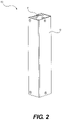
- FIG. 2 is a perspective view of an energy cell, according to an example embodiment of the present disclosure
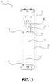
- FIG. 3 is a cross-sectional view of the energy cell of FIG. 2 , according to an example embodiment of the present disclosure
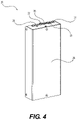
- FIG. 4 is a perspective view of a battery management system (BMS) cell, according to an example embodiment of the present disclosure
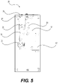
- FIG. 5 is a cross-sectional view of the BMS cell of FIG. 4 , according to an example embodiment of the present disclosure
- FIG. 6 is a perspective view of a wiring harness, according to an example embodiment of the present disclosure.
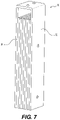
- FIG. 7 is a perspective view of a ballast cell, according to an example embodiment of the present disclosure.
- FIGS. 8-10 are photographs of components of the battery system, according to example embodiments of the present disclosure.
- FIGS. 11A-11D depict an embodiment of a ballasted energy cell, according to an example embodiment of the present disclosure.
- FIGS. 12A-12E depict an embodiment of a battery system including a top wall and a plurality of ballast bars, according to an example embodiment.
- Embodiments of the present disclosure provide a modular battery as described herein.
- Embodiments of the presently disclosed modular battery include a lithium-ion cell module containing paralleled cells and an optionally provided ballast/counterweight, as well as a connection method.
- This design uniquely incorporates counterweights/ballasts with the lithium-ion cell and a battery management system (BMS) cell, combining the two in a casing.
- BMS battery management system
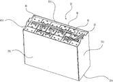
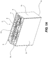
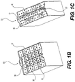
- a battery system 50 is constructed from a combination of a plurality of energy cells 10 , at least one BMS cell 20 , and (optionally) at least one ballast element (depicted as ballast cell 30 ) disposed within an interior cavity of a casing 60 . Because of the unique design, the end user may configure a counterweighted battery (for use, for example, with forklifts) at a variety of voltages ranging from 12V to 80V or more, from the same type of cell.
- the battery system 50 includes the energy cells 10 and BMS cells 20 , and the at least one ballast element may be separate from the energy cells 10 and the BMS cell 20 and/or incorporated into one or more of the energy cells 10 and the BMS cell 20 .
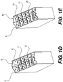
- the battery system 50 may include separate ballast elements, shown as individual ballast cells 30 in FIGS. 1A-1D .
- the battery system 50 may contain only the plurality of energy cells 10 and the at least one BMS cell 20 .
- the casing 60 includes a plurality of sidewalls 61 a - d and a bottom wall 61 e . Additionally, in certain embodiments, the casing 60 includes a separate top wall, which is not depicted in order to show the interior cavity and contents of the casing 60 . In such embodiments, the top wall may be reversibly or permanently attached to any one or more of the sidewalls 61 a - d or to one or more of the cells 10 , 20 , 30 , in particular the ballast cells 30 , in the interior cavity.
- the sidewalls 61 a - d of the casing 60 as shown in FIGS.
- the size of the rectangular perimeter can vary depending on the size of the equipment powered by the battery system 50 .
- the size and shape of the casing 60 may vary depending on the space available for the casing 60 in its given installation. For example, if the battery system 50 is powering a forklift, the size and the shape of the battery compartment on the forklift may dictate the size and shape of the casing 60 for the battery system 50 .
- the casing 60 does not have a rectangular perimeter, and the sidewalls may define another curved or polygonal shape.
- FIG. 2 depicts an exterior view of an energy cell 10 according to an exemplary embodiment.
- Each energy cell 10 includes a plugging point 11 and a protective exterior case 12 .
- the plugging point 11 includes an opening through the exterior case 12 to provide a location for the power connection, and in one or more embodiments, the plugging point 11 may include a temperature sensor or other sensors.
- the protective exterior case 12 may be formed from a metal, such as steel, or from various types of plastic.
- the energy cell 10 may further include a plug receptacle 13 accessed through the plugging point 11 (as shown in FIG. 2 ) to allow external connections.
- the plug receptacle 13 is in electrical communication with a first terminal wire 16 connected to a first battery electrode 15 and a second terminal wire 18 connected to a second battery electrode 17 .
- Disposed between the battery electrodes 15 , 17 are one or more lithium ion cell modules 62 .
- the lithium ion cell modules 62 produce electrical energy through the movement of lithium ions between an anode and a cathode within each cell module 62 .
- the lithium ion cell modules 62 are connected in parallel between the electrodes 15 , 17 .
- the energy cell 10 may also include thermal sensor wires 14 and a temperature sensor 19 .
- the thermal sensor wires 14 may provide temperature information to the BMS cell 20 for management of the energy cell 10 .
- the temperature sensor 19 may be embodied as a “snap switch” to turn the contactor/transistor power off if overheating occurs.
- FIG. 4 depicts an embodiment of an exterior of a BMS cell 20 according to an exemplary embodiment.
- the BMS cell 20 includes a BMS balance wire output 23 , a power input/output port 24 , and a battery port 25 .
- the power input/output port 24 provides external connection to the system powered by the battery system 50 or to a charger for charging the battery system 50 .
- the power input/output port 24 may be configured to receive a single plug as shown in FIG. 4 , and in one or more other embodiments, separate power input and power output ports may be provided to receive separate power input and power output cables.
- the battery port 25 is connected to the energy cells 10 and is configured to receive electrical energy from or distribute electrical energy to the energy cells 10 .
- the balance wire output 23 is configured to balance the output of the energy cells 10 to provide a consistent voltage output for the battery system 50 .
- the BMS cell 20 may be configured to provide active or passive balancing of the energy cells 10 through the balance wire output 23 .
- the BMS cell 20 may also include a switch with status lights 21 and a data connection port 22 .
- the switch and status lights 21 may allow for reset of the BMS cell 20 with the status lights indicating a current state of the BMS cell 20 .
- the data connection port 22 may allow for collection of diagnostic and performance information regarding operation of the BMS cell 20 .
- the BMS cell also includes a protective exterior case 26 .
- the protective exterior case 26 may be formed from any suitable metal or plastic material.
- FIG. 5 depicts an interior view of a BMS cell according to an exemplary embodiment.
- the BMS cell 20 may include a battery management system control board 63 configured to, e.g., actively or passively balance the energy cells, monitor operating temperature, protect against over-current or over- (or under-) voltage conditions, and provide information (e.g., through data connection port 22 ) regarding the state and performance of the battery system 50 .
- battery management control boards 63 are known in the art (for example, Orion Jr. BMS2, available from Ewert Energy Systems, Inc., Carol Stream, Ill.).
- the battery management system control board 63 is connected to the battery port 25 to receive electrical energy (in a discharge mode) from the plurality of energy cells 10 and manage their operation.
- the battery management system control board 63 provides (in a discharge mode) the electrical energy output to a plug receptacle 28 of the power input/output port 24 . In a charge mode, the battery management system control board 63 receives electrical energy through the power input/output port 24 and distributes it through the battery port 25 to the energy cells 10 to charge them.
- a relay 35 and a fuse 29 may be provided intermediate of the battery management control board 63 and the power input/output port 24 to protect the BMS cell 20 from over-voltage or over-current.
- the BMS cell 20 may also include a limit switch 27 positioned adjacent to an input/output power plug 28 .
- a plurality of wires 64 connect the components of the BMS cell 20 .
- FIG. 6 depicts a wiring harness 40 configured to connect the plurality of energy cells 10 and the at least one BMS cell 20 .
- the wiring harness 40 includes a plurality of plugs 41 and wires 42 connecting the plugs 41 .
- the wiring harness 40 provides a series connection between the plugs 41 such that, when the plugs 41 are inserted into the plug receptacles 13 of the energy cells 10 (as shown in FIG. 2 ), the energy cells 10 are connected in series.
- the plugs 41 carry the voltage to and from the BMS cell 20 , and in one or more embodiments, the wiring harness 40 includes from three to twenty-two plugs.
- FIG. 6 depicts an output connector 43 configured to carry the electrical energy to the system powered by the battery system 50 .
- FIG. 7 depicts an embodiment of a ballast element.
- FIG. 7 depicts a ballast element in the form of a ballast cell 30 that is separate from the energy cells 10 , BMS cell 20 , and casing 60 .
- the ballast cell 30 includes an exterior case 32 .
- the exterior case 32 is designed to fit in spaces between or around the energy cells 10 and BMS cell 20 .
- Disposed within the exterior case 32 are a plurality of ballast plates 31 . The number and material of the plates may be selected based on the desired amount of ballasting to be provided by the ballast cell 30 .
- the ballast plates 31 may be made from steel.
- the battery system 50 includes a plurality of energy cells 10 , a BMS cell 20 , and (optionally) a plurality of ballast cells 30 .
- the cells 10 , 20 , 30 in FIGS. 1A-1D are arranged in a grid pattern with the cells 10 , 20 , 30 organized into a plurality of rows and columns.
- the battery system 50 includes rows having three cells and columns having six cells.
- a first row includes two ballast cells 30 around a single energy cell 10 .
- the second row includes three energy cells 10 .
- the third row includes two energy cells 10 and one ballast cell 30 .
- the fourth row also includes two energy cells 10 and one ballast cell 30 , but the ballast cell 30 is on the opposite side of the row as compared to the third row.
- the fifth row includes two energy cells 10 disposed on either side of half of the BMS cell 20
- the sixth row includes two ballast cells 30 disposed on either side of the other half of the BMS cell 20 .
- the energy cells 10 and the ballast cells 30 are approximately the same size (i.e., have substantially the same height, width, and length), and the BMS cell 20 is twice the size of the energy cells 10 and the ballast cells 30 (in particular, twice the length or width but having the same height).
- the plurality of energy cells 10 , the at least one BMS cell 20 , and the ballast cells 30 are individually insertable and removable from the casing 60 without inserting or removing any of the other of the plurality of energy cells 10 , the at least one BMS cell 20 , and the ballast cells 30 .
- the plurality of energy cells 10 , the at least one BMS cell 20 , and the ballast cells 30 are only connected by the wiring harness 40 and frictional engagement between the exterior cases of the cells 10 , 20 , 30 .
- the placement of the cells 10 , 20 , 30 in the casing 60 can be customized for particular applications (such as, for example, to place the output connector 43 in a certain position within the battery system 50 or to distribute the ballast weight over a particular area) by inserting and arranging the desired number of cells 10 , 20 , 30 within the casing 60 .
- FIG. 1E depicts a battery system 50 including only the plurality of energy cells 10 and the at least one BMS cell 20 . That is, the battery system 50 of FIG. 1E does not include a ballast element (other than the weight of the cells 10 , 20 and the casing 60 ). Such battery systems 50 may be used for applications in which a counterweight is not needed, such as stationary energy storage or for certain autonomous guided vehicles. Such a battery system 50 has the many of the same advantages as described above, including the high customizability and ease of arrangement of the cells 10 , 20 within the casing 60 .
- FIG. 8 depicts an embodiment of an energy cell 10 according to the present disclosure and produced by the assignee of the present disclosure.
- FIG. 9 depicts an embodiment of a ballast cell 30 according to the present disclosure and produced by the assignee of the present disclosure.
- FIG. 10 depicts an embodiment of a casing 60 containing a plurality of energy cells 10 and ballast cells 30 in which the energy cells 10 are connected by a wiring harness 40 .
- the casing 60 of FIG. 10 did not yet have a BMS cell 20 inserted therein at the time the picture was taken.
- the casing 60 , energy cells 10 , ballast cells 30 , and wiring harness 40 are assembled by the assignee of the present disclosure.
- FIGS. 11A-11D another embodiment of an energy cell 10 is depicted.
- the energy cell 10 is substantially the same as the energy cell 10 of FIGS. 2 and 3 , but the energy cell 10 of FIGS. 11A-11D includes a ballast element within the protective case 12 .
- the energy cell 10 includes a plugging point 11 and a protective case 12 .
- the size of the cell 10 defined by the protective case 12 is larger than the previously described and depicted embodiments of the energy cell 10 .
- FIG. 11B depicts a first cross-sectional view of the energy cell 10 in which the lithium ion cell module 62 can be seen. Further, as shown in FIG.
- the lithium ion cell module 62 is surrounded by a plurality of ballast weights 65 .
- the exterior case 12 of the energy cell 10 includes a first face and a second face that is spatially disposed from the first face. The faces of the energy cell 10 are connected by four sides as shown in FIGS. 11A-11D .
- the ballast weight 35 may be provided on at least two of the four sides of the exterior case 12 . In particular embodiments, no weight is provided on the side of the exterior case 12 providing an opening for the plug receptacle 13 .
- FIG. 11C depicts another cross-sectional view of the energy cell 10 in which the electrical connections can be seen.
- the plug receptacle 13 is connected to a first terminal wire 16 leading to the first battery electrode 15
- the plug receptacle 13 is also connected to a second terminal wire 18 leading to the second battery electrode 17 .
- Disposed between the battery electrodes 15 , 17 are a plurality of lithium ion cell modules 62 .
- the cell module, containing the lithium-ion cells and additional weight, are connected to the battery system 50 .
- Energy cells 10 constructed according to the concepts illustrated in FIGS. 11A-11D provide energy to connected equipment, while the additional weight added to the energy cell 10 provides counter ballast for equipment.
- the cell can be connected into a battery system that is then connected to equipment not requiring counterweight.
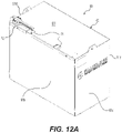
- FIGS. 12A-12E depict another embodiment of the battery system 50 .
- FIG. 12A is a perspective view of the battery system 50 .
- the casing 60 includes an optional top wall 61 f
- the top wall 61 f is reversibly joined to two of the side walls 61 b , 61 d using, e.g., fasteners, such as screws.
- the top wall 61 f includes openings 71 through which a charging/discharging cable 72 extends.
- the top wall 61 f includes two openings 71 , which allow for separate charging and discharging cables to extend through the top wall 61 f.
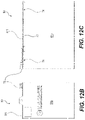
- FIGS. 12B and 12C depict a front view and a side view, respectively, of the battery system 50 .
- FIG. 12B shows a front side wall 61 a of the casing 60
- the opposing rear side wall 61 c is substantially similar to the front side wall 61 a .
- FIG. 12C depicts a first lateral side wall 61 b
- the opposing second lateral side wall 61 d is substantially similar to the first lateral side wall 61 b .
- the top wall 61 f includes a lip 73 that extends over the first and second lateral side walls 61 b , 61 d of the casing but not over the front and rear side walls 61 a , 61 c .
- top wall 61 f is secured to the lateral side walls 61 b , 61 d using one or more fasteners, and in particular, FIG. 12C depicts the lip 73 of the top wall 61 f secured to the first lateral side walls 61 b using two screws 74 , and the top wall 61 f may be secured to the second lateral side wall 61 d in the same way.
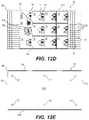
- FIG. 12D depicts a top view of the battery system 50 without the top wall 61 f .
- the casing 60 holds a plurality of energy cells 10 and a BMS cell 20 .
- the plurality of energy cells 10 and the BMS cell 20 can be connected with a wiring harness 40 (such as shown in FIG. 6 ).
- the BMS cell 20 includes separate power input (charging) and power output (discharging) ports 24 a , 24 b .
- the BMS cell 20 includes a data connection port 22 for obtaining diagnostic and performance information from the battery management system control board 63 and a battery port 25 for connecting to the plurality of energy cells 10 .
- the plurality of energy cells 10 include plugging points 11 with plug receptacles 13 for connecting to the wiring harness (not shown).
- FIG. 12D further depicts the ballast element of the battery system 50 in the form of a plurality of ballast bars 75 .
- the ballast bars 75 comprise a material having a density sufficient to provide the desired ballasting effect within the space constraints of the casing 60 , such as, for example, steel.
- the ballast bars 75 have a cross-sectional dimension of 1 inch by 1 inch and a length up to the height of the lateral side walls 61 b , 61 d .
- the ballast bars 75 are positioned on either side of a central block of the plurality of energy cells 10 and the BMS cell 20 . In the example embodiment shown in FIG.
- the ballast bars 75 are arranged in six columns of nineteen ballast bars 75 on each side for a total of 288 ballast bars 75 .
- the ballast bars 75 can provide, e.g., 2000 lbs of ballasting weight or more.
- the ballast bars 75 can be interspersed among the plurality of energy cells 10 and the BMS cell 20 .
- the ballasting weight of the battery system 50 can be tailored to the particular needs of the installation powered by the battery system 50 .
- the remainder of the space in the interior cavity of the casing 60 can be filled with low density materials, such as plastic or wood, which act as shims to prevent movement of the ballast bars 75 .
- the interior cavity of the casing 60 may be provided with panels 76 of, e.g., a low density material, such as a plastic material, to define layers in which the ballast bars 75 can be inserted.
- the panels 76 may intersect to define a grid having slots configured to hold one or a subset of ballast bars 75 .
- FIG. 12E depicts the bottom wall 61 e of the casing 60 .
- the bottom wall 61 e includes a plurality of apertures 77 that allow for draining of moisture or circulation of air through the battery system 50 .
- a method of making the presently disclosed modular battery system 50 may include fabricating the metal components of the cells 10 , 20 , 30 and casing 60 with traditional metal-cutting and metal-forming processes.
- the cells 10 , 20 , 30 and casing 60 are then assembled with hand tools or automated processes, using a combination of fasteners and, potentially but not necessarily, having a welding process to join weights and/or the outer cell casing together.
- a method of using the present disclosed modular battery system 50 may include inserting the energy cells 10 together with a BMS cell 20 and the ballast element within a casing 60 .
- the wiring harness 40 electrically connects the energy cells 10 and BMS cells 20 .
- the battery system 50 would then be connected to equipment that requires electrical power.
- the battery system 50 in accordance with the present disclosure, provides both electrical energy and, optionally, counter ballasting weight to the equipment.
Landscapes
- Chemical & Material Sciences (AREA)
- Chemical Kinetics & Catalysis (AREA)
- Electrochemistry (AREA)
- General Chemical & Material Sciences (AREA)
- Engineering & Computer Science (AREA)
- Microelectronics & Electronic Packaging (AREA)
- Manufacturing & Machinery (AREA)
- Battery Mounting, Suspending (AREA)
Abstract
Description
- This patent application claims the benefit of U.S. Provisional Patent Application No. 63/198,674, filed Nov. 3, 2020, the entire teachings and disclosure of which are incorporated herein by reference thereto.
- The present invention relates to battery cells and, more particularly, to a ballasted lithium-ion battery cell for use in industrial equipment.
- There are many applications where a battery must have a minimum weight. Other conventional cells do not include counterweights, and so batteries must be weighted separately, or equipment must have a separate counterweight added if a battery cannot contain the counterweight. The requirement of adding counterweight separately of the lithium-ion cell adds design and manufacturing complexity.
- In view of the foregoing, Applicant has identified a need for a modular battery cell that solves the above problems.
- In one aspect, embodiments of the present disclosure provide a modular battery. The modular battery includes a casing having sidewalls and a bottom wall defining an interior cavity. The modular battery also includes a plurality of energy cells disposed within the interior cavity, and each energy cell of the plurality of energy cells includes at least one lithium ion cell module. Further, the modular battery includes at least one battery management system (BMS) cell disposed within the interior cavity, and the at least one BMS cell is configured to coordinate input of electrical energy into and output of electrical energy from the plurality of energy cells. A wiring harness electrically connects the plurality of energy cells and the at least one BMS cell, and (optionally) a ballast element is disposed within the interior cavity. In the modular battery, each energy cell of the plurality of energy cells and each BMS cell of the at least one BMS cell are individually insertable and removable from the interior cavity without insertion or removal of any other energy cell of the plurality of energy cells or any other BMS cell of the at least one BMS cell.
- In another aspect, embodiments of the present disclosure provide an energy cell. The energy cell includes an exterior case having an interior. At least one lithium ion cell module is disposed on the interior of the exterior case. Further, ballast weight is disposed on the interior of the exterior case and around the at least one lithium ion cell module.
- In yet another aspect, the invention provides a method of assembling a modular battery. In the method, a plurality of energy cells and at least one BMS cell are inserted in an interior cavity of a casing. Each energy cell of the plurality of energy cells includes at least one lithium ion cell module. Further, the at least one BMS cell is configured to coordinate input of electrical energy into and output of electrical energy from the plurality of energy cells. In the method, the plurality of energy cells and the at least one battery management system cell are connected with a wiring harness. In one or more embodiments, each energy cell of the plurality of energy cells and each BMS cell of the at least one BMS cell are individually insertable in the interior cavity.
- Other aspects, objectives and advantages of the invention will become more apparent from the following detailed description when taken in conjunction with the accompanying drawings.
- The accompanying drawings incorporated in and forming a part of the specification illustrate several aspects of the present invention and, together with the description, serve to explain the principles of the invention. In the drawings:
-
FIGS. 1A-1E depict perspective views of battery systems having a variety of shapes and sizes, according to example embodiments of the present disclosure; -
FIG. 2 is a perspective view of an energy cell, according to an example embodiment of the present disclosure; -
FIG. 3 is a cross-sectional view of the energy cell ofFIG. 2 , according to an example embodiment of the present disclosure; -
FIG. 4 is a perspective view of a battery management system (BMS) cell, according to an example embodiment of the present disclosure; -
FIG. 5 is a cross-sectional view of the BMS cell ofFIG. 4 , according to an example embodiment of the present disclosure; -
FIG. 6 is a perspective view of a wiring harness, according to an example embodiment of the present disclosure; -
FIG. 7 is a perspective view of a ballast cell, according to an example embodiment of the present disclosure; -
FIGS. 8-10 are photographs of components of the battery system, according to example embodiments of the present disclosure; -
FIGS. 11A-11D depict an embodiment of a ballasted energy cell, according to an example embodiment of the present disclosure; and -
FIGS. 12A-12E depict an embodiment of a battery system including a top wall and a plurality of ballast bars, according to an example embodiment. - While the invention will be described in connection with certain preferred embodiments, there is no intent to limit it to those embodiments. On the contrary, the intent is to cover all alternatives, modifications and equivalents as included within the spirit and scope of the invention as defined by the appended claims.
- The following detailed description is of the best currently contemplated modes of carrying out exemplary embodiments of the present invention. The description is not to be taken in a limiting sense but is made merely for the purpose of illustrating the general principles of the present invention.
- Broadly, embodiments of the present disclosure provide a modular battery as described herein. Embodiments of the presently disclosed modular battery include a lithium-ion cell module containing paralleled cells and an optionally provided ballast/counterweight, as well as a connection method. This design uniquely incorporates counterweights/ballasts with the lithium-ion cell and a battery management system (BMS) cell, combining the two in a casing. The complexity of adding a separate counterweight is removed due to the additional mass added within the casing of the presently disclosed modular battery.
- Referring now to
FIGS. 1-10 , the present invention relates to a modular lithium-ion battery design. As shown inFIGS. 1A-1E , abattery system 50 is constructed from a combination of a plurality ofenergy cells 10, at least oneBMS cell 20, and (optionally) at least one ballast element (depicted as ballast cell 30) disposed within an interior cavity of acasing 60. Because of the unique design, the end user may configure a counterweighted battery (for use, for example, with forklifts) at a variety of voltages ranging from 12V to 80V or more, from the same type of cell. In certain embodiments that include the ballast element, thebattery system 50 includes theenergy cells 10 andBMS cells 20, and the at least one ballast element may be separate from theenergy cells 10 and theBMS cell 20 and/or incorporated into one or more of theenergy cells 10 and theBMS cell 20. For example, thebattery system 50 may include separate ballast elements, shown asindividual ballast cells 30 inFIGS. 1A-1D . However, as shown inFIG. 1E , thebattery system 50 may contain only the plurality ofenergy cells 10 and the at least oneBMS cell 20. - As shown in
FIG. 1A , thecasing 60 includes a plurality of sidewalls 61 a-d and abottom wall 61 e. Additionally, in certain embodiments, thecasing 60 includes a separate top wall, which is not depicted in order to show the interior cavity and contents of thecasing 60. In such embodiments, the top wall may be reversibly or permanently attached to any one or more of the sidewalls 61 a-d or to one or more of thecells ballast cells 30, in the interior cavity. The sidewalls 61 a-d of thecasing 60, as shown inFIGS. 1A-1D , define a rectangular perimeter of thecasing 60, and as shown inFIGS. 1A-1D , the size of the rectangular perimeter can vary depending on the size of the equipment powered by thebattery system 50. Additionally, the size and shape of thecasing 60 may vary depending on the space available for thecasing 60 in its given installation. For example, if thebattery system 50 is powering a forklift, the size and the shape of the battery compartment on the forklift may dictate the size and shape of thecasing 60 for thebattery system 50. In other embodiments, thecasing 60 does not have a rectangular perimeter, and the sidewalls may define another curved or polygonal shape. -
FIG. 2 depicts an exterior view of anenergy cell 10 according to an exemplary embodiment. Eachenergy cell 10 includes a pluggingpoint 11 and aprotective exterior case 12. The pluggingpoint 11 includes an opening through theexterior case 12 to provide a location for the power connection, and in one or more embodiments, the pluggingpoint 11 may include a temperature sensor or other sensors. Theprotective exterior case 12 may be formed from a metal, such as steel, or from various types of plastic. As shown inFIG. 3 , theenergy cell 10 may further include aplug receptacle 13 accessed through the plugging point 11 (as shown inFIG. 2 ) to allow external connections. Theplug receptacle 13 is in electrical communication with afirst terminal wire 16 connected to afirst battery electrode 15 and asecond terminal wire 18 connected to asecond battery electrode 17. Disposed between thebattery electrodes ion cell modules 62. The lithiumion cell modules 62 produce electrical energy through the movement of lithium ions between an anode and a cathode within eachcell module 62. In one or more embodiments, the lithiumion cell modules 62 are connected in parallel between theelectrodes - In one or more embodiments, the
energy cell 10 may also includethermal sensor wires 14 and atemperature sensor 19. In one or more embodiments, thethermal sensor wires 14 may provide temperature information to theBMS cell 20 for management of theenergy cell 10. According to certain embodiments, thetemperature sensor 19 may be embodied as a “snap switch” to turn the contactor/transistor power off if overheating occurs. -
FIG. 4 depicts an embodiment of an exterior of aBMS cell 20 according to an exemplary embodiment. In one or more embodiments, theBMS cell 20 includes a BMSbalance wire output 23, a power input/output port 24, and abattery port 25. The power input/output port 24 provides external connection to the system powered by thebattery system 50 or to a charger for charging thebattery system 50. In one or more embodiments, the power input/output port 24 may be configured to receive a single plug as shown inFIG. 4 , and in one or more other embodiments, separate power input and power output ports may be provided to receive separate power input and power output cables. Thebattery port 25 is connected to theenergy cells 10 and is configured to receive electrical energy from or distribute electrical energy to theenergy cells 10. In one or more embodiments, thebalance wire output 23 is configured to balance the output of theenergy cells 10 to provide a consistent voltage output for thebattery system 50. In one or more embodiments, theBMS cell 20 may be configured to provide active or passive balancing of theenergy cells 10 through thebalance wire output 23. - In one or more embodiments, the
BMS cell 20 may also include a switch withstatus lights 21 and adata connection port 22. The switch andstatus lights 21 may allow for reset of theBMS cell 20 with the status lights indicating a current state of theBMS cell 20. Thedata connection port 22 may allow for collection of diagnostic and performance information regarding operation of theBMS cell 20. - As shown in
FIG. 4 , the BMS cell also includes aprotective exterior case 26. Like theenergy cell 10, theprotective exterior case 26 may be formed from any suitable metal or plastic material. -
FIG. 5 depicts an interior view of a BMS cell according to an exemplary embodiment. In one or more embodiments, theBMS cell 20 may include a battery managementsystem control board 63 configured to, e.g., actively or passively balance the energy cells, monitor operating temperature, protect against over-current or over- (or under-) voltage conditions, and provide information (e.g., through data connection port 22) regarding the state and performance of thebattery system 50. Such batterymanagement control boards 63 are known in the art (for example, Orion Jr. BMS2, available from Ewert Energy Systems, Inc., Carol Stream, Ill.). The battery managementsystem control board 63 is connected to thebattery port 25 to receive electrical energy (in a discharge mode) from the plurality ofenergy cells 10 and manage their operation. The battery managementsystem control board 63 provides (in a discharge mode) the electrical energy output to aplug receptacle 28 of the power input/output port 24. In a charge mode, the battery managementsystem control board 63 receives electrical energy through the power input/output port 24 and distributes it through thebattery port 25 to theenergy cells 10 to charge them. - In one or more embodiments, a
relay 35 and afuse 29 may be provided intermediate of the batterymanagement control board 63 and the power input/output port 24 to protect theBMS cell 20 from over-voltage or over-current. In one or more embodiments, theBMS cell 20 may also include alimit switch 27 positioned adjacent to an input/output power plug 28. A plurality ofwires 64 connect the components of theBMS cell 20. -
FIG. 6 depicts awiring harness 40 configured to connect the plurality ofenergy cells 10 and the at least oneBMS cell 20. In the embodiment shown inFIG. 6 , thewiring harness 40 includes a plurality ofplugs 41 andwires 42 connecting theplugs 41. In one or more embodiments, including the embodiment shown inFIG. 6 , thewiring harness 40 provides a series connection between theplugs 41 such that, when theplugs 41 are inserted into theplug receptacles 13 of the energy cells 10 (as shown inFIG. 2 ), theenergy cells 10 are connected in series. Theplugs 41 carry the voltage to and from theBMS cell 20, and in one or more embodiments, thewiring harness 40 includes from three to twenty-two plugs. In embodiments, theplugs 41 are connected in series; however, in other embodiments, all or a subset of theplugs 41 may be connected in parallel. Additionally,FIG. 6 depicts anoutput connector 43 configured to carry the electrical energy to the system powered by thebattery system 50. -
FIG. 7 depicts an embodiment of a ballast element. In particular,FIG. 7 depicts a ballast element in the form of aballast cell 30 that is separate from theenergy cells 10,BMS cell 20, andcasing 60. In one or more embodiments, theballast cell 30 includes anexterior case 32. In certain embodiments, theexterior case 32 is designed to fit in spaces between or around theenergy cells 10 andBMS cell 20. Disposed within theexterior case 32 are a plurality ofballast plates 31. The number and material of the plates may be selected based on the desired amount of ballasting to be provided by theballast cell 30. For example, in embodiments, theballast plates 31 may be made from steel. - Referring back to
FIGS. 1A-1E , thebattery system 50 includes a plurality ofenergy cells 10, aBMS cell 20, and (optionally) a plurality ofballast cells 30. As can be seen, thecells FIGS. 1A-1D are arranged in a grid pattern with thecells FIG. 1A , thebattery system 50 includes rows having three cells and columns having six cells. InFIG. 1A , a first row includes twoballast cells 30 around asingle energy cell 10. The second row includes threeenergy cells 10. The third row includes twoenergy cells 10 and oneballast cell 30. The fourth row also includes twoenergy cells 10 and oneballast cell 30, but theballast cell 30 is on the opposite side of the row as compared to the third row. The fifth row includes twoenergy cells 10 disposed on either side of half of theBMS cell 20, and the sixth row includes twoballast cells 30 disposed on either side of the other half of theBMS cell 20. Thus, in the embodiment shown inFIG. 1A , theenergy cells 10 and theballast cells 30 are approximately the same size (i.e., have substantially the same height, width, and length), and theBMS cell 20 is twice the size of theenergy cells 10 and the ballast cells 30 (in particular, twice the length or width but having the same height). - The plurality of
energy cells 10, the at least oneBMS cell 20, and theballast cells 30 are individually insertable and removable from thecasing 60 without inserting or removing any of the other of the plurality ofenergy cells 10, the at least oneBMS cell 20, and theballast cells 30. In other words, the plurality ofenergy cells 10, the at least oneBMS cell 20, and theballast cells 30 are only connected by thewiring harness 40 and frictional engagement between the exterior cases of thecells cells cells casing 60 can be customized for particular applications (such as, for example, to place theoutput connector 43 in a certain position within thebattery system 50 or to distribute the ballast weight over a particular area) by inserting and arranging the desired number ofcells casing 60. -
FIG. 1E depicts abattery system 50 including only the plurality ofenergy cells 10 and the at least oneBMS cell 20. That is, thebattery system 50 ofFIG. 1E does not include a ballast element (other than the weight of thecells Such battery systems 50 may be used for applications in which a counterweight is not needed, such as stationary energy storage or for certain autonomous guided vehicles. Such abattery system 50 has the many of the same advantages as described above, including the high customizability and ease of arrangement of thecells casing 60. -
FIG. 8 depicts an embodiment of anenergy cell 10 according to the present disclosure and produced by the assignee of the present disclosure.FIG. 9 depicts an embodiment of aballast cell 30 according to the present disclosure and produced by the assignee of the present disclosure.FIG. 10 depicts an embodiment of acasing 60 containing a plurality ofenergy cells 10 andballast cells 30 in which theenergy cells 10 are connected by awiring harness 40. Thecasing 60 ofFIG. 10 did not yet have aBMS cell 20 inserted therein at the time the picture was taken. Thecasing 60,energy cells 10,ballast cells 30, andwiring harness 40 are assembled by the assignee of the present disclosure. - Referring now to
FIGS. 11A-11D , another embodiment of anenergy cell 10 is depicted. In such embodiments, theenergy cell 10 is substantially the same as theenergy cell 10 ofFIGS. 2 and 3 , but theenergy cell 10 ofFIGS. 11A-11D includes a ballast element within theprotective case 12. As shown inFIG. 11A , theenergy cell 10 includes a pluggingpoint 11 and aprotective case 12. In the embodiment depicted, the size of thecell 10 defined by theprotective case 12 is larger than the previously described and depicted embodiments of theenergy cell 10.FIG. 11B depicts a first cross-sectional view of theenergy cell 10 in which the lithiumion cell module 62 can be seen. Further, as shown inFIG. 11B , the lithiumion cell module 62 is surrounded by a plurality ofballast weights 65. In embodiments, theexterior case 12 of theenergy cell 10 includes a first face and a second face that is spatially disposed from the first face. The faces of theenergy cell 10 are connected by four sides as shown inFIGS. 11A-11D . Theballast weight 35 may be provided on at least two of the four sides of theexterior case 12. In particular embodiments, no weight is provided on the side of theexterior case 12 providing an opening for theplug receptacle 13. -
FIG. 11C depicts another cross-sectional view of theenergy cell 10 in which the electrical connections can be seen. In particular, theplug receptacle 13 is connected to afirst terminal wire 16 leading to thefirst battery electrode 15, and theplug receptacle 13 is also connected to asecond terminal wire 18 leading to thesecond battery electrode 17. Disposed between thebattery electrodes ion cell modules 62. The cell module, containing the lithium-ion cells and additional weight, are connected to thebattery system 50.Energy cells 10 constructed according to the concepts illustrated inFIGS. 11A-11D provide energy to connected equipment, while the additional weight added to theenergy cell 10 provides counter ballast for equipment. Optionally, the cell can be connected into a battery system that is then connected to equipment not requiring counterweight. -
FIGS. 12A-12E depict another embodiment of thebattery system 50.FIG. 12A is a perspective view of thebattery system 50. As can be seen inFIG. 12A , thecasing 60 includes an optionaltop wall 61 f In the embodiment depicted, thetop wall 61 f is reversibly joined to two of theside walls top wall 61 f includesopenings 71 through which a charging/dischargingcable 72 extends. In the embodiment shown inFIG. 12A , thetop wall 61 f includes twoopenings 71, which allow for separate charging and discharging cables to extend through thetop wall 61 f. -
FIGS. 12B and 12C depict a front view and a side view, respectively, of thebattery system 50.FIG. 12B shows afront side wall 61 a of thecasing 60, and the opposingrear side wall 61 c is substantially similar to thefront side wall 61 a.FIG. 12C depicts a firstlateral side wall 61 b, and the opposing secondlateral side wall 61 d is substantially similar to the firstlateral side wall 61 b. In one or more embodiments, thetop wall 61 f includes alip 73 that extends over the first and secondlateral side walls rear side walls top wall 61 f is secured to thelateral side walls FIG. 12C depicts thelip 73 of thetop wall 61 f secured to the firstlateral side walls 61 b using twoscrews 74, and thetop wall 61 f may be secured to the secondlateral side wall 61 d in the same way. -
FIG. 12D depicts a top view of thebattery system 50 without thetop wall 61 f. As can be seen inFIG. 12D , thecasing 60 holds a plurality ofenergy cells 10 and aBMS cell 20. While not depicted, the plurality ofenergy cells 10 and theBMS cell 20 can be connected with a wiring harness 40 (such as shown inFIG. 6 ). TheBMS cell 20 includes separate power input (charging) and power output (discharging)ports BMS cell 20 includes adata connection port 22 for obtaining diagnostic and performance information from the battery managementsystem control board 63 and abattery port 25 for connecting to the plurality ofenergy cells 10. Further, the plurality ofenergy cells 10 include pluggingpoints 11 withplug receptacles 13 for connecting to the wiring harness (not shown). - In
FIG. 12D further depicts the ballast element of thebattery system 50 in the form of a plurality of ballast bars 75. In one or more embodiments, the ballast bars 75 comprise a material having a density sufficient to provide the desired ballasting effect within the space constraints of thecasing 60, such as, for example, steel. In one or more such embodiments, the ballast bars 75 have a cross-sectional dimension of 1 inch by 1 inch and a length up to the height of thelateral side walls FIG. 12D , the ballast bars 75 are positioned on either side of a central block of the plurality ofenergy cells 10 and theBMS cell 20. In the example embodiment shown inFIG. 12D , the ballast bars 75 are arranged in six columns of nineteenballast bars 75 on each side for a total of 288 ballast bars 75. In this way, the ballast bars 75 can provide, e.g., 2000 lbs of ballasting weight or more. In one or more other embodiments, the ballast bars 75 can be interspersed among the plurality ofenergy cells 10 and theBMS cell 20. - By providing a plurality of ballast bars 75 as the ballasting element of the
battery system 50, the ballasting weight of thebattery system 50 can be tailored to the particular needs of the installation powered by thebattery system 50. For example, once the desired ballasting weight is achieved with the ballasting bars 75, the remainder of the space in the interior cavity of thecasing 60 can be filled with low density materials, such as plastic or wood, which act as shims to prevent movement of the ballast bars 75. Further, in one or more embodiments, the interior cavity of thecasing 60 may be provided withpanels 76 of, e.g., a low density material, such as a plastic material, to define layers in which the ballast bars 75 can be inserted. In one or more embodiments, thepanels 76 may intersect to define a grid having slots configured to hold one or a subset of ballast bars 75. -
FIG. 12E depicts thebottom wall 61 e of thecasing 60. In one or more embodiments, thebottom wall 61 e includes a plurality ofapertures 77 that allow for draining of moisture or circulation of air through thebattery system 50. - A method of making the presently disclosed
modular battery system 50 may include fabricating the metal components of thecells casing 60 with traditional metal-cutting and metal-forming processes. Thecells casing 60 are then assembled with hand tools or automated processes, using a combination of fasteners and, potentially but not necessarily, having a welding process to join weights and/or the outer cell casing together. - A method of using the present disclosed
modular battery system 50 may include inserting theenergy cells 10 together with aBMS cell 20 and the ballast element within acasing 60. Thewiring harness 40 electrically connects theenergy cells 10 andBMS cells 20. Thebattery system 50 would then be connected to equipment that requires electrical power. Thebattery system 50, in accordance with the present disclosure, provides both electrical energy and, optionally, counter ballasting weight to the equipment. - All references, including publications, patent applications, and patents cited herein are hereby incorporated by reference to the same extent as if each reference were individually and specifically indicated to be incorporated by reference and were set forth in its entirety herein.
- The use of the terms “a” and “an” and “the” and similar referents in the context of describing the invention (especially in the context of the following claims) is to be construed to cover both the singular and the plural, unless otherwise indicated herein or clearly contradicted by context. The terms “comprising,” “having,” “including,” and “containing” are to be construed as open-ended terms (i.e., meaning “including, but not limited to,”) unless otherwise noted. Recitation of ranges of values herein are merely intended to serve as a shorthand method of referring individually to each separate value falling within the range, unless otherwise indicated herein, and each separate value is incorporated into the specification as if it were individually recited herein. All methods described herein can be performed in any suitable order unless otherwise indicated herein or otherwise clearly contradicted by context. The use of any and all examples, or exemplary language (e.g., “such as”) provided herein, is intended merely to better illuminate the invention and does not pose a limitation on the scope of the invention unless otherwise claimed. No language in the specification should be construed as indicating any non-claimed element as essential to the practice of the invention.
- Preferred embodiments of this invention are described herein, including the best mode known to the inventors for carrying out the invention. Variations of those preferred embodiments may become apparent to those of ordinary skill in the art upon reading the foregoing description. The inventors expect skilled artisans to employ such variations as appropriate, and the inventors intend for the invention to be practiced otherwise than as specifically described herein. Accordingly, this invention includes all modifications and equivalents of the subject matter recited in the claims appended hereto as permitted by applicable law. Moreover, any combination of the above-described elements in all possible variations thereof is encompassed by the invention unless otherwise indicated herein or otherwise clearly contradicted by context.
Claims (20)
Priority Applications (6)
| Application Number | Priority Date | Filing Date | Title |
|---|---|---|---|
| US17/517,550 US12476289B2 (en) | 2020-11-03 | 2021-11-02 | Modular battery |
| CA3199677A CA3199677A1 (en) | 2020-11-03 | 2021-11-03 | Modular battery |
| MX2023004682A MX2023004682A (en) | 2020-11-03 | 2021-11-03 | Modular battery. |
| PCT/US2021/057889 WO2022098752A1 (en) | 2020-11-03 | 2021-11-03 | Modular battery |
| EP21889981.3A EP4241330A4 (en) | 2020-11-03 | 2021-11-03 | MODULAR BATTERY |
| US19/365,927 US20260045568A1 (en) | 2020-11-03 | 2025-10-22 | Modular battery |
Applications Claiming Priority (2)
| Application Number | Priority Date | Filing Date | Title |
|---|---|---|---|
| US202063198674P | 2020-11-03 | 2020-11-03 | |
| US17/517,550 US12476289B2 (en) | 2020-11-03 | 2021-11-02 | Modular battery |
Related Child Applications (1)
| Application Number | Title | Priority Date | Filing Date |
|---|---|---|---|
| US19/365,927 Continuation US20260045568A1 (en) | 2020-11-03 | 2025-10-22 | Modular battery |
Publications (2)
| Publication Number | Publication Date |
|---|---|
| US20220140407A1 true US20220140407A1 (en) | 2022-05-05 |
| US12476289B2 US12476289B2 (en) | 2025-11-18 |
Family
ID=81379189
Family Applications (2)
| Application Number | Title | Priority Date | Filing Date |
|---|---|---|---|
| US17/517,550 Active 2042-12-31 US12476289B2 (en) | 2020-11-03 | 2021-11-02 | Modular battery |
| US19/365,927 Pending US20260045568A1 (en) | 2020-11-03 | 2025-10-22 | Modular battery |
Family Applications After (1)
| Application Number | Title | Priority Date | Filing Date |
|---|---|---|---|
| US19/365,927 Pending US20260045568A1 (en) | 2020-11-03 | 2025-10-22 | Modular battery |
Country Status (5)
| Country | Link |
|---|---|
| US (2) | US12476289B2 (en) |
| EP (1) | EP4241330A4 (en) |
| CA (1) | CA3199677A1 (en) |
| MX (1) | MX2023004682A (en) |
| WO (1) | WO2022098752A1 (en) |
Cited By (4)
| Publication number | Priority date | Publication date | Assignee | Title |
|---|---|---|---|---|
| US20220411016A1 (en) * | 2021-06-23 | 2022-12-29 | Orbea, S. Coop. | Compact battery for electric bicycles |
| CN119764714A (en) * | 2024-12-23 | 2025-04-04 | 惠州亿纬锂能股份有限公司 | Battery pack, battery pack assembly method and power-consuming device |
| DE102024106237A1 (en) * | 2024-03-05 | 2025-09-11 | Jungheinrich Aktiengesellschaft | Arrangement of at least one traction battery and at least one counterweight of an industrial truck |
| DE102024106239A1 (en) * | 2024-03-05 | 2025-10-02 | Jungheinrich Aktiengesellschaft | Industrial truck and traction battery and use of the same |
Citations (12)
| Publication number | Priority date | Publication date | Assignee | Title |
|---|---|---|---|---|
| US6368743B1 (en) * | 1999-06-04 | 2002-04-09 | Delphi Technologies, Inc. | Compact battery package |
| US20060134514A1 (en) * | 2004-12-17 | 2006-06-22 | Hawker Sarl | Battery including a plurality of cells placed side by side in a case |
| US20080011553A1 (en) * | 2006-06-30 | 2008-01-17 | Jungheinrich Aktiengesellschaft | Battery pack for an industrial truck |
| US20080050645A1 (en) * | 2006-07-31 | 2008-02-28 | Hitachi Vehicle Energy, Ltd. | Cell controller, battery module and power supply system |
| US20110045335A1 (en) * | 2009-04-01 | 2011-02-24 | Lg Chem, Ltd. | Battery module having flexibility in designing structure of module and battery pack employed with the same |
| JP2012009311A (en) * | 2010-06-25 | 2012-01-12 | Sanyo Electric Co Ltd | Storage system of electricity |
| US20130273412A1 (en) * | 2010-10-30 | 2013-10-17 | Wataru Okada | Battery pack and vehicle including the same |
| US20150030889A1 (en) * | 2012-03-16 | 2015-01-29 | Nec Corporation | Power storage device |
| US20170170438A1 (en) * | 2015-12-14 | 2017-06-15 | General Electric Company | Battery packaging system and method for a vehicle |
| JP2017111899A (en) * | 2015-12-15 | 2017-06-22 | 株式会社豊田自動織機 | Battery pack and battery pack manufacturing method |
| US20180351144A1 (en) * | 2017-05-30 | 2018-12-06 | Artisan Vehicle Systems Inc. | Multi-Modular Battery System |
| RU199889U1 (en) * | 2020-05-27 | 2020-09-24 | Общество с ограниченной ответственностью "Экологичные технологии" | BATTERY UNIT |
Family Cites Families (49)
| Publication number | Priority date | Publication date | Assignee | Title |
|---|---|---|---|---|
| US3887396A (en) | 1973-11-15 | 1975-06-03 | Us Energy | Modular electrochemical cell |
| JPH04366547A (en) | 1991-06-12 | 1992-12-18 | Matsushita Electric Ind Co Ltd | Gas depolarizing assembling battery |
| WO1993012554A1 (en) | 1991-12-16 | 1993-06-24 | Matsi, Inc. | Collapsing foam anode backing for zinc-air battery |
| US5445099A (en) | 1993-09-20 | 1995-08-29 | Rendina; David D. | Hydrogen hydride keel |
| US5666029A (en) | 1994-05-03 | 1997-09-09 | The Bodine Company | Fluorescent emergency ballast self test circuit |
| US5811938A (en) | 1995-06-01 | 1998-09-22 | The Bodine Company, Inc. | Emergency lighting ballast for starting and operating two compact fluorescent lamps with integral starter |
| US5814971A (en) | 1997-12-29 | 1998-09-29 | National Service Industries, Inc. | Emergency florescent inverter for magnetic and electronic ballasts |
| US6273015B1 (en) | 1998-02-26 | 2001-08-14 | Maruta Electric Boatworks Llc | Stabilized electric watercraft for high speed cruising, diving and sailing |
| JP2000014043A (en) | 1998-06-05 | 2000-01-14 | Internatl Business Mach Corp <Ibm> | Uninterruptive power supply |
| EP1020973A3 (en) | 1999-01-18 | 2001-05-02 | Hitachi, Ltd. | A charge and discharge system for electric power storage equipment |
| JP3466576B2 (en) | 2000-11-14 | 2003-11-10 | 三井鉱山株式会社 | Composite material for negative electrode of lithium secondary battery and lithium secondary battery |
| EP1399361A1 (en) | 2001-06-18 | 2004-03-24 | University Of Florida Research Foundation, Inc. | Method and apparatus for lightning protection |
| AU2003292781A1 (en) | 2002-12-26 | 2004-07-22 | Fuji Jukogyo Kabushiki Kaisha | Electrical storage device and method for manufacturing electrical storage device |
| JP5098150B2 (en) | 2004-12-07 | 2012-12-12 | 日産自動車株式会社 | Bipolar battery and manufacturing method thereof |
| US7211983B2 (en) | 2005-02-24 | 2007-05-01 | Heuliez | Amphibious off-road vehicle |
| JP4439456B2 (en) | 2005-03-24 | 2010-03-24 | 株式会社東芝 | Battery pack and automobile |
| JP4782663B2 (en) | 2006-11-29 | 2011-09-28 | パナソニック株式会社 | Charging system, charging device, and battery pack |
| US8119288B2 (en) | 2007-11-05 | 2012-02-21 | Nanotek Instruments, Inc. | Hybrid anode compositions for lithium ion batteries |
| US20090226802A1 (en) | 2008-01-31 | 2009-09-10 | Night Operations Systems | Connector for battery pack of lighting system |
| US20090283024A1 (en) | 2008-03-18 | 2009-11-19 | William Joseph Robertson | Battery Keel System and Method |
| US7880391B2 (en) | 2008-06-30 | 2011-02-01 | Osram Sylvania, Inc. | False failure prevention circuit in emergency ballast |
| US8640629B2 (en) | 2009-05-01 | 2014-02-04 | Norfolk Southern Corporation | Battery-powered all-electric and/or hybrid locomotive and related locomotive and train configurations |
| TWI484683B (en) | 2009-05-11 | 2015-05-11 | Univ Arizona | Metal-air low temperature ionic liquid cell |
| WO2011022517A2 (en) | 2009-08-18 | 2011-02-24 | Cooper Technologies Company | Ballast for fluorescent emergency lighting |
| US8877361B2 (en) | 2009-09-01 | 2014-11-04 | Samsung Sdi Co., Ltd. | Rechargeable battery |
| CN102082309B (en) | 2009-11-27 | 2014-09-17 | 尹学军 | Method for quickly supplementing electric energy of electric vehicle and power supply unit thereof |
| CN201936953U (en) | 2009-12-31 | 2011-08-17 | 杭州万马高能量电池有限公司 | Lithium ion accumulator with exclusive use of starting motorcycle |
| US20110181234A1 (en) | 2010-04-01 | 2011-07-28 | Branham Michael K | Mobile modular solar power system |
| US20110300429A1 (en) | 2010-06-08 | 2011-12-08 | Mswhorter Edward Milton | Automotive ballast battery |
| DE102010038308A1 (en) | 2010-07-23 | 2012-01-26 | Evonik Degussa Gmbh | Lithium cells and batteries with improved stability and safety, process for their preparation and use in mobile and stationary electrical energy storage |
| KR101198026B1 (en) | 2010-12-02 | 2012-11-06 | 주식회사 엘지화학 | Secondary Battery Pack of Novel Structure |
| CN103797609B (en) | 2011-04-28 | 2016-12-14 | 佐尔循环公司 | Latch mechanism for battery retention |
| US20140220461A1 (en) | 2011-10-13 | 2014-08-07 | Toyota Jidosha Kabushiki Kaisha | Air battery, mobile object comprising the air battery and method for using an air battery |
| US9005794B2 (en) | 2011-10-21 | 2015-04-14 | Tyco Electronics Corporation | Battery connector system |
| JP6136230B2 (en) | 2012-01-16 | 2017-05-31 | 株式会社Gsユアサ | Battery pack and power supply device |
| KR101433666B1 (en) | 2012-02-07 | 2014-08-25 | 주식회사 엘지화학 | Method for Battery Cell Having Uncoated Part of Battery Case |
| US10485073B1 (en) | 2012-06-15 | 2019-11-19 | Aleddra Inc. | Solid-state lighting with dual mode operations |
| JP6123299B2 (en) | 2013-01-11 | 2017-05-10 | 株式会社豊田自動織機 | Battery pack and industrial vehicle |
| KR101586668B1 (en) | 2013-12-27 | 2016-01-19 | 주식회사 엘지화학 | Battery Module Assembly Including Sub-Modules Inside |
| JP2015133834A (en) | 2014-01-14 | 2015-07-23 | 日東電工株式会社 | Wireless power transmission device and manufacturing method thereof |
| JP2015154593A (en) | 2014-02-14 | 2015-08-24 | ソニー株式会社 | Charge/discharge control device, battery pack, electronic apparatus, electric motor vehicle and charge/discharge control method |
| CN106797013B (en) | 2014-07-02 | 2021-02-05 | 维金电力系统有限公司 | Multi-electrode electrochemical cell and method of making same |
| US20160020618A1 (en) | 2014-07-21 | 2016-01-21 | Ford Global Technologies, Llc | Fast Charge Algorithms for Lithium-Ion Batteries |
| AU2017201690B2 (en) | 2016-03-14 | 2022-09-15 | The Raymond Corporation | Battery counterweight system |
| JP7203080B2 (en) | 2017-07-13 | 2023-01-12 | イーコントロールズ エルエルシー | Modular lithium-ion battery system for forklifts |
| WO2019126360A1 (en) | 2017-12-21 | 2019-06-27 | Pellion Technologies Inc. | Electrochemical cell and electrolyte for same |
| KR102029131B1 (en) | 2017-12-27 | 2019-10-07 | 세방전지(주) | Medium and large size battery pack of industrial electric vehicle capable of weight balancing |
| US20220052411A1 (en) | 2018-11-28 | 2022-02-17 | Cadenza Innovation, Inc. | Modular Battery System |
| TWI703757B (en) | 2019-05-22 | 2020-09-01 | 車王電子股份有限公司 | Battery box with counterweight |
-
2021
- 2021-11-02 US US17/517,550 patent/US12476289B2/en active Active
- 2021-11-03 CA CA3199677A patent/CA3199677A1/en active Pending
- 2021-11-03 EP EP21889981.3A patent/EP4241330A4/en active Pending
- 2021-11-03 WO PCT/US2021/057889 patent/WO2022098752A1/en not_active Ceased
- 2021-11-03 MX MX2023004682A patent/MX2023004682A/en unknown
-
2025
- 2025-10-22 US US19/365,927 patent/US20260045568A1/en active Pending
Patent Citations (12)
| Publication number | Priority date | Publication date | Assignee | Title |
|---|---|---|---|---|
| US6368743B1 (en) * | 1999-06-04 | 2002-04-09 | Delphi Technologies, Inc. | Compact battery package |
| US20060134514A1 (en) * | 2004-12-17 | 2006-06-22 | Hawker Sarl | Battery including a plurality of cells placed side by side in a case |
| US20080011553A1 (en) * | 2006-06-30 | 2008-01-17 | Jungheinrich Aktiengesellschaft | Battery pack for an industrial truck |
| US20080050645A1 (en) * | 2006-07-31 | 2008-02-28 | Hitachi Vehicle Energy, Ltd. | Cell controller, battery module and power supply system |
| US20110045335A1 (en) * | 2009-04-01 | 2011-02-24 | Lg Chem, Ltd. | Battery module having flexibility in designing structure of module and battery pack employed with the same |
| JP2012009311A (en) * | 2010-06-25 | 2012-01-12 | Sanyo Electric Co Ltd | Storage system of electricity |
| US20130273412A1 (en) * | 2010-10-30 | 2013-10-17 | Wataru Okada | Battery pack and vehicle including the same |
| US20150030889A1 (en) * | 2012-03-16 | 2015-01-29 | Nec Corporation | Power storage device |
| US20170170438A1 (en) * | 2015-12-14 | 2017-06-15 | General Electric Company | Battery packaging system and method for a vehicle |
| JP2017111899A (en) * | 2015-12-15 | 2017-06-22 | 株式会社豊田自動織機 | Battery pack and battery pack manufacturing method |
| US20180351144A1 (en) * | 2017-05-30 | 2018-12-06 | Artisan Vehicle Systems Inc. | Multi-Modular Battery System |
| RU199889U1 (en) * | 2020-05-27 | 2020-09-24 | Общество с ограниченной ответственностью "Экологичные технологии" | BATTERY UNIT |
Non-Patent Citations (3)
| Title |
|---|
| Abstract of JP 2012009311A (Year: 2012) * |
| Machine Translation of JP 2017111899A (Year: 2017) * |
| Machine Translation of RU 199889u1 (Year: 2020) * |
Cited By (4)
| Publication number | Priority date | Publication date | Assignee | Title |
|---|---|---|---|---|
| US20220411016A1 (en) * | 2021-06-23 | 2022-12-29 | Orbea, S. Coop. | Compact battery for electric bicycles |
| DE102024106237A1 (en) * | 2024-03-05 | 2025-09-11 | Jungheinrich Aktiengesellschaft | Arrangement of at least one traction battery and at least one counterweight of an industrial truck |
| DE102024106239A1 (en) * | 2024-03-05 | 2025-10-02 | Jungheinrich Aktiengesellschaft | Industrial truck and traction battery and use of the same |
| CN119764714A (en) * | 2024-12-23 | 2025-04-04 | 惠州亿纬锂能股份有限公司 | Battery pack, battery pack assembly method and power-consuming device |
Also Published As
| Publication number | Publication date |
|---|---|
| EP4241330A1 (en) | 2023-09-13 |
| US12476289B2 (en) | 2025-11-18 |
| WO2022098752A1 (en) | 2022-05-12 |
| EP4241330A4 (en) | 2024-10-30 |
| CA3199677A1 (en) | 2022-05-12 |
| US20260045568A1 (en) | 2026-02-12 |
| MX2023004682A (en) | 2023-07-20 |
Similar Documents
| Publication | Publication Date | Title |
|---|---|---|
| US12476289B2 (en) | Modular battery | |
| CN100472848C (en) | Secondary battery pack having staggered directional structure | |
| US10211434B2 (en) | Battery pack | |
| US7892669B2 (en) | Middle or large-sized battery module | |
| JP5296884B2 (en) | Battery pack | |
| KR101106544B1 (en) | Unit pack combination cell cartridge | |
| KR101016596B1 (en) | Cell cartridge consisting of intercell interconnection | |
| EP3424094B1 (en) | Battery pack | |
| KR101287108B1 (en) | Secondary battery module | |
| WO2022134055A1 (en) | Battery box body, battery, electric device, and method and device for manufacturing box body | |
| KR102235650B1 (en) | Secondary battery module, and secondary battery pack including the same | |
| JP6092771B2 (en) | Battery cell module, battery, and vehicle | |
| JP2018006314A (en) | Battery submodule carrier, battery submodule, battery system, and vehicle | |
| KR20120055156A (en) | Battery module having novel structure and battery pack employed with the same | |
| KR20210036902A (en) | Secondary battery module, and secondary battery pack including the same | |
| US20150207178A1 (en) | Battery module | |
| JP2004006122A (en) | Assembled battery unit and connector of assembled battery unit | |
| CN118782986A (en) | Battery cells, batteries and electrical equipment | |
| CN222610943U (en) | High voltage boxes, batteries, electrical devices and energy storage devices | |
| EP4723420A1 (en) | Energy storage apparatus and energy storage system | |
| EP4567995A1 (en) | Battery pack and vehicle including same | |
| US20260038941A1 (en) | Modular Battery Frame Assembly | |
| US20240266662A1 (en) | Sodium-based battery for hybrid vehicles | |
| WO2026031541A1 (en) | Battery cell, battery device and electric apparatus | |
| KR20240012282A (en) | Battery pack and vehicle including same |
Legal Events
| Date | Code | Title | Description |
|---|---|---|---|
| FEPP | Fee payment procedure |
Free format text: ENTITY STATUS SET TO UNDISCOUNTED (ORIGINAL EVENT CODE: BIG.); ENTITY STATUS OF PATENT OWNER: SMALL ENTITY |
|
| AS | Assignment |
Owner name: BLUE LINE BATTERY, INC., WISCONSIN Free format text: ASSIGNMENT OF ASSIGNORS INTEREST;ASSIGNOR:HERTE, DUSTIN JAY;REEL/FRAME:058005/0376 Effective date: 20211102 |
|
| FEPP | Fee payment procedure |
Free format text: ENTITY STATUS SET TO SMALL (ORIGINAL EVENT CODE: SMAL); ENTITY STATUS OF PATENT OWNER: SMALL ENTITY |
|
| STPP | Information on status: patent application and granting procedure in general |
Free format text: DOCKETED NEW CASE - READY FOR EXAMINATION |
|
| STPP | Information on status: patent application and granting procedure in general |
Free format text: NON FINAL ACTION MAILED |
|
| STPP | Information on status: patent application and granting procedure in general |
Free format text: RESPONSE TO NON-FINAL OFFICE ACTION ENTERED AND FORWARDED TO EXAMINER |
|
| STPP | Information on status: patent application and granting procedure in general |
Free format text: FINAL REJECTION MAILED |
|
| STPP | Information on status: patent application and granting procedure in general |
Free format text: RESPONSE AFTER FINAL ACTION FORWARDED TO EXAMINER |
|
| STPP | Information on status: patent application and granting procedure in general |
Free format text: ADVISORY ACTION MAILED |
|
| STPP | Information on status: patent application and granting procedure in general |
Free format text: DOCKETED NEW CASE - READY FOR EXAMINATION |
|
| STPP | Information on status: patent application and granting procedure in general |
Free format text: NON FINAL ACTION MAILED |
|
| STPP | Information on status: patent application and granting procedure in general |
Free format text: RESPONSE TO NON-FINAL OFFICE ACTION ENTERED AND FORWARDED TO EXAMINER |
|
| STPP | Information on status: patent application and granting procedure in general |
Free format text: NOTICE OF ALLOWANCE MAILED -- APPLICATION RECEIVED IN OFFICE OF PUBLICATIONS |
|
| STPP | Information on status: patent application and granting procedure in general |
Free format text: PUBLICATIONS -- ISSUE FEE PAYMENT RECEIVED |
|
| STPP | Information on status: patent application and granting procedure in general |
Free format text: PUBLICATIONS -- ISSUE FEE PAYMENT VERIFIED |
|
| STCF | Information on status: patent grant |
Free format text: PATENTED CASE |