US20210394251A1 - Riveting device and riveting method - Google Patents
Riveting device and riveting method Download PDFInfo
- Publication number
- US20210394251A1 US20210394251A1 US17/352,694 US202117352694A US2021394251A1 US 20210394251 A1 US20210394251 A1 US 20210394251A1 US 202117352694 A US202117352694 A US 202117352694A US 2021394251 A1 US2021394251 A1 US 2021394251A1
- Authority
- US
- United States
- Prior art keywords
- riveting
- rivet
- pressurizing
- axial line
- shaft portion
- Prior art date
- Legal status (The legal status is an assumption and is not a legal conclusion. Google has not performed a legal analysis and makes no representation as to the accuracy of the status listed.)
- Granted
Links
Images


Classifications
-
- B—PERFORMING OPERATIONS; TRANSPORTING
- B21—MECHANICAL METAL-WORKING WITHOUT ESSENTIALLY REMOVING MATERIAL; PUNCHING METAL
- B21J—FORGING; HAMMERING; PRESSING METAL; RIVETING; FORGE FURNACES
- B21J15/00—Riveting
- B21J15/02—Riveting procedures
- B21J15/04—Riveting hollow rivets mechanically
-
- B—PERFORMING OPERATIONS; TRANSPORTING
- B21—MECHANICAL METAL-WORKING WITHOUT ESSENTIALLY REMOVING MATERIAL; PUNCHING METAL
- B21J—FORGING; HAMMERING; PRESSING METAL; RIVETING; FORGE FURNACES
- B21J15/00—Riveting
- B21J15/02—Riveting procedures
-
- B—PERFORMING OPERATIONS; TRANSPORTING
- B21—MECHANICAL METAL-WORKING WITHOUT ESSENTIALLY REMOVING MATERIAL; PUNCHING METAL
- B21J—FORGING; HAMMERING; PRESSING METAL; RIVETING; FORGE FURNACES
- B21J15/00—Riveting
- B21J15/10—Riveting machines
- B21J15/36—Rivet sets, i.e. tools for forming heads; Mandrels for expanding parts of hollow rivets
-
- F—MECHANICAL ENGINEERING; LIGHTING; HEATING; WEAPONS; BLASTING
- F16—ENGINEERING ELEMENTS AND UNITS; GENERAL MEASURES FOR PRODUCING AND MAINTAINING EFFECTIVE FUNCTIONING OF MACHINES OR INSTALLATIONS; THERMAL INSULATION IN GENERAL
- F16B—DEVICES FOR FASTENING OR SECURING CONSTRUCTIONAL ELEMENTS OR MACHINE PARTS TOGETHER, e.g. NAILS, BOLTS, CIRCLIPS, CLAMPS, CLIPS OR WEDGES; JOINTS OR JOINTING
- F16B19/00—Bolts without screw-thread; Pins, including deformable elements; Rivets
- F16B19/04—Rivets; Spigots or the like fastened by riveting
- F16B19/06—Solid rivets made in one piece
-
- F—MECHANICAL ENGINEERING; LIGHTING; HEATING; WEAPONS; BLASTING
- F16—ENGINEERING ELEMENTS AND UNITS; GENERAL MEASURES FOR PRODUCING AND MAINTAINING EFFECTIVE FUNCTIONING OF MACHINES OR INSTALLATIONS; THERMAL INSULATION IN GENERAL
- F16B—DEVICES FOR FASTENING OR SECURING CONSTRUCTIONAL ELEMENTS OR MACHINE PARTS TOGETHER, e.g. NAILS, BOLTS, CIRCLIPS, CLAMPS, CLIPS OR WEDGES; JOINTS OR JOINTING
- F16B5/00—Joining sheets or plates, e.g. panels, to one another or to strips or bars parallel to them
- F16B5/04—Joining sheets or plates, e.g. panels, to one another or to strips or bars parallel to them by means of riveting
Definitions
- the present disclosure relates to a riveting device and a riveting method that deform a rivet inserted into a through-hole formed in a plurality of plate-shaped members disposed in a superimposed state and secure the plurality of plate-shaped members.
- a device that forms a through-hole in two or more members in an aircraft body panel or the like and deforms a fastener inserted into the through-hole to secure the two or more members is known (see Japanese Unexamined Patent Application, Publication No. 2018-122354, for example).
- the device disclosed in Japanese Unexamined Patent Application, Publication No. 2018-122354 is adapted to apply a force of causing a pair of dies disposed both at a head portion and at an end portion of a shaft portion of the fastener to approach each other and plastically deform the fastener.
- Japanese Unexamined Patent Application, Publication No. 2018-122354 discloses that a surface of a die with a cup shape is caused to abut on a tail end of the fastener to plastically deform the tail end.
- the present invention was made in view of the aforementioned problem, and an object thereof is to provide a riveting device and a riveting method that enable excessive plastic deformation of an end surface of a shaft portion of a rivet in a radial direction to be curved and enable degradation of fatigue strength at a part fastened with the rivet due to formation of a clearance between the shaft portion and a through-hole to be prevented.
- the present disclosure employs the following solutions.
- a riveting device is a riveting device that deforms a rivet inserted into a through-hole formed in a plurality of plate-shaped members disposed in a superimposed state and secures the plurality of plate-shaped members, the rivet including a shaft portion that extends along an axial line and has a first outer diameter in a radial direction that perpendicularly intersects the axial line and a head that is coupled to the shaft portion and has a second outer diameter that is larger than the first outer diameter in the radial direction, the riveting device including: a first riveting member that has a support surface disposed in a state in which the support surface faces a first end surface of the head; a second riveting member that has a pressurizing surface disposed in a state in which the pressurizing surface faces a second end surface of the shaft portion; and a pressurizing mechanism that generates a pressurizing force of causing a distance between the first riveting member and the second riveting member along the axial line to
- a riveting method is a riveting method of deforming a rivet inserted into a through-hole formed in a plurality of plate-shaped members disposed in a superimposed state and securing the plurality of plate-shaped members, the rivet including a shaft portion that extends along an axial line and has a first outer diameter in a radial direction that perpendicularly intersects the axial line and a head that is coupled to the shaft portion and has a second outer diameter that is larger than the first outer diameter in the radial direction, the riveting method including: a first disposing process of disposing a support surface of a first riveting member in a state in which the support surface faces a first end surface of the head; a second disposing process of disposing a pressurizing surface of a second riveting member in a state in which the pressurizing surface faces a second end surface of the shaft portion; and a riveting process of generating a pressurizing force of causing a distance between the first riveting member and
- a riveting device and a riveting method that enable excessive plastic deformation of the end surface of the shaft portion of the rivet in the radial direction to be curbed and enable degradation of fatigue strength of a part fastened with the rivet due to formation of a clearance between the shaft portion and the through-hole to be prevented.
- FIG. 1 is a sectional view illustrating a riveting device according to an embodiment of the present disclosure and illustrates a state before a rivet is plastically deformed;
- FIG. 2 is a sectional view illustrating the riveting device according to the embodiment of the present disclosure and illustrates a state after the rivet is plastically deformed;
- FIG. 3 is a sectional view illustrating the rivet before plastic deformation
- FIG. 4 is a plan view of an end surface of a head of the rivet illustrated in FIG. 3 when seen along an axial line;
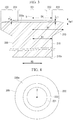
- FIG. 5 is a partially enlarged view illustrating a section of an upper anvil
- FIG. 6 is a plan view of an end surface of the upper anvil when seen along the axial line;
- FIG. 7 is a plan view of an end surface of a shaft portion of the rivet when seen along the axial line;
- FIG. 8 is a plan view of a pressurizing surface of a lower anvil when seen along the axial line;
- FIG. 9 is a diagram illustrating sections of the rivet and plate-shaped members in a case in which the rivet is plastically deformed by the riveting device according to the present embodiment.
- FIG. 10 is a diagram illustrating sections of the rivet and the plate-shaped members in a case in which the rivet is plastically deformed by a riveting device according to a comparative example.
- the riveting device 100 is a device that plastically deforms a rivet 200 inserted into a through-hole 330 formed in a plurality of plate-shaped members 310 and 320 disposed in a superimposed state and secures the plurality of plate-shaped members 310 and 320 .
- the plurality of plate-shaped members 310 and 320 are, for example, aircraft body panels.
- the plurality of plate-shaped members 310 and e 20 are formed using an aluminum alloy, for example. Although an example in which two plate-shaped members are disposed in a superimposed manner will be described in the present embodiment, an arbitrary number, such as three or more, of plate-shaped members may be disposed in a superimposed manner.
- FIG. 1 is a sectional view illustrating the riveting device 100 according to the embodiment of the present disclosure and illustrates a state before a rivet 200 is plastically deformed.
- FIG. 2 is a sectional view illustrating the riveting device 100 according to the embodiment of the present disclosure and illustrates a state after the rivet 200 is plastically deformed.
- the plate-shaped member 310 disposed on the upper side is supported by a cylindrical upper support body 410 extending along an axial line X.
- the plate-shaped member 320 disposed on the lower side is supported by a cylindrical lower support body 420 extending along the axial line X.
- the plate-shaped member 310 and the plate-shaped member 320 are disposed in a state in which the plate-shaped member 310 and the plate-shaped member 320 are secured at predetermined positions on the axial line X by being supported by the upper support body 410 and the lower support body 420 in a sandwiched state.
- the axial line X is a linear line extending in a direction that perpendicularly intersects planes in which the plurality of plate-shaped members 310 and 320 are disposed.
- the through-hole 330 extending along the axial line X is formed in the plate-shaped member 310 and the plate-shaped member 320 .
- the through-hole 330 is formed in the plate-shaped member 310 and the plate-shaped member 320 supported in a superimposed state by the upper support body 410 and the lower support body 420 using a punching mechanism (not illustrated) that moves forward and backward along the axial line X.
- a counterbore portion 331 for accommodating a head 220 of the rivet 200 is formed at an end portion of the through-hole 330 on the upper side.
- the riveting device 100 includes an upper anvil (first riveting member) 110 , a lower anvil (second riveting member) 120 , and a pressurizing mechanism 130 .
- the upper anvil 110 and the lower anvil 120 are formed using an iron-based metal material containing iron such as tool steel, for example, as a main constituent.
- the upper anvil 110 is a member formed into a shaft shape extending along the axial line X and includes an end surface 110 a that is disposed in a state in which the end surface 110 a faces an end surface (first end surface) 220 a of the head 220 of the rivet 200 inserted into the through-hole 330 .
- the upper anvil 110 can be moved along the axial line X by the pressurizing mechanism 130 (upper pressurizing mechanism 131 ) and is disposed in a state in which the upper anvil 110 is in contact with the end surface 220 a of the head 220 of the rivet 200 when a riveting operation of plastically deforming the rivet 200 is performed.
- the lower anvil 120 is a member formed into a shaft shape extending along the axial line X and includes a pressurizing surface 120 a disposed in a state in which the pressurizing surface 120 a faces an end surface (second end surface) 210 a of a shaft portion 210 of the rivet 200 .
- the lower anvil 120 can be moved along the axial line X by the pressurizing mechanism 130 (lower pressurizing mechanism 132 ) and is disposed in a state in which the lower anvil 120 is in contact with the end surface 210 a of the shaft portion 210 of the rivet 200 when the riveting operation of plastically deforming the rivet 200 is performed.
- the pressurizing mechanism 130 is a mechanism that generates a pressurizing force of causing the distance between the upper anvil 110 and the lower anvil 120 along the axial line X to decrease and plastically deforms the rivet 200 .
- the pressurizing mechanism 130 includes an upper pressurizing mechanism 131 that causes the upper anvil 110 to move along the axial line X and a lower pressurizing mechanism 132 that causes the lower anvil 120 to move along the axial line X.
- the pressurizing mechanism 130 causes the lower anvil 120 to move from the position separated from the shaft portion 210 as illustrated in FIG. 1 to the position at which the lower anvil 120 comes into contact with the shaft portion 210 as illustrated in FIG. 2 in a state in which the end surface 110 a of the upper anvil 110 is in contact with the end surface 220 a of the head 220 of the rivet 200 .
- the pressurizing mechanism 130 thus applies a pressurizing force to the rivet 200 and plastically deforms the rivet 200 . As illustrated in FIG.
- the shaft portion 210 of the rivet on the side of the end surface 210 a is plastically deformed due to the pressurizing force applied by the pressurizing mechanism 130 and is plastically deformed into a substantially cylindrica shape with a larger outer diameter than the inner diameter of the through-hole 330 .
- a support surface 112 of the upper anvil 110 is disposed in a state in which the support surface 112 faces and comes into contact with the end surface 220 a of the head 220 of the rivet 200 , as illustrated in FIG. 1 (first disposing process).
- the pressurizing surface 120 a of the lower anvil 120 is disposed in a state in which the pressurizing surface 120 a of the lower anvil 120 faces the end surface 210 a of the shaft portion 210 , as illustrated in FIG. 1 (second disposing process).
- the pressurizing mechanism 130 generates a pressurizing force of causing the distance between the upper anvil 110 and the lower anvil 120 along the axial line X to decrease and plastically deforms the rivet 200 , as illustrated in FIG. 2 (riveting process).
- the riveting device 100 plastically deforms the rivet 200 inserted into the through-hole 330 formed in the plurality of plate-shaped members 310 and 320 disposed in a superimposed state and secures the plurality of plate-shaped members 310 and 320 .
- FIG. 3 is a sectional view illustrating the rivet 200 before plastic deformation.
- FIG. 4 is a plan view of the end surface 220 a of the head 220 f the rivet 200 illustrated in FIG. 3 when seen along the axial line X.
- the rivet 200 is a member that is inserted into the through-hole 330 formed in the plate-shaped member 310 and the plate-shaped member 320 and secures the plate-shaped member 310 and the plate-shaped member 320 through plastic deformation.
- the rivet 200 is formed using an aluminum alloy, for example.
- the rivet 200 includes the shaft portion 210 and the head 220 .
- the shaft portion 210 extends along the axial line X and has an outer diameter (first outer diameter) D 1 in a radial direction RD that perpendicularly intersects the axial line X.
- the head 220 is coupled to the shaft portion 210 and has an outer diameter (second outer diameter) D 2 that is larger than the outer diameter D 1 in the radial direction RD.
- the outer diameter D 1 is, for example, 5 to 8 mm.
- a flat surface 221 , an inclined surface 222 , and a coupling surface 223 are formed in the end surface 220 a of the head 220 .
- the flat surface 221 is a surface that perpendicularly intersects the axial line X and is formed into a circular and flat shape with the axial line X located at the center.
- the inclined surface 222 is disposed on the outer circumferential side in the radial direction RD beyond the flat surface 221 .
- the inclined surface 222 is formed into an annual shape around the axial line X and has a projecting length L 1 in the direction of the axial line X with respect to the flat surface 221 gradually decreasing with a constant gradient from the inner circumferential side toward the outer circumferential side in the radial direction RD.
- the coupling surface 223 is a surface that is formed into an annular shape around the axial line X and couples the flat surface 221 and the inclined surface 222 .
- the coupling surface 223 is disposed on the outer circumferential side in the radial direction RD beyond the flat surface 221 and is disposed on the inner circumferential side in the radial direction RD beyond the inclined surface 222 .
- the coupling surface 223 has a projecting length in the direction of the axial line X with respect to the flat surface 221 gradually increasing with a constant gradient from the inner circumferential side toward the outer circumferential side in the radial direction RD.
- the inclination angle of the inclined surface 222 with respect to a plane that perpendicularly intersects the axial line X is ⁇ , which is constant at each position in the circumferential direction around the axial line X.
- FIG. 5 is a partially enlarged view illustrating a section of the upper anvil 110 .
- FIG. 6 is a plan view of the end surface 110 a of the upper anvil 110 when seen along the axial line X.
- a bottom surface 111 and the support surface 112 are formed in the end surface 110 a of the upper anvil 110 .
- the bottom surface 111 perpendicularly intersects the axial line X and is formed into a circular and flat shape with the axial line X located at the center.
- the support surface 112 is a surface that supports the inclined surface 222 of the rivet 200 when the riveting operation is executed and is disposed on the outer circumferential side in the radial direction RD beyond the bottom surface 111 .
- the support surface 112 is formed into an annular shape around the axial line X and has a projecting length L 2 in the direction of the axial line X with respect to the bottom surface 111 gradually increasing with a constant gradient from the inner circumferential side toward the outer circumferential side in the radial direction RD.
- the inclination angle of the support surface 112 with respect to the plane that perpendicularly intersects the axial line X is ⁇ , which is constant at each position in the circumferential direction around the axial line X.
- the inclination angle ⁇ of the support surface 112 with respect to the plane that perpendicularly intersects the axial line X is smaller than the inclination angle ⁇ of the inclined surface 222 with respect to the plane that perpendicularly intersects the axial line X by a predetermined angle A.
- the inclination angle ⁇ and the inclination angle ⁇ are set to satisfy Expression (1) below.
- the predetermined angle A is set to be equal to or greater than 0.5 degrees and equal to or less than 5.0 degrees. Also, the predetermined angle A is preferably set to be equal to or greater than 2.0 degrees and equal to or less than 2.5 degrees.
- the distance in the direction of the axial line X from the end portion of the support surface 112 of the upper anvil 110 on the inner circumferential side in the radial direction RD to the end portion of the support surface 112 on the outer circumferential side in the radial direction RD is Lp 2 .
- the distance in the direction of the axial line X from the end portion of the inclined surface 222 of the rivet 200 on the inner circumferential side in the radial direction RD to the end portion of the inclined surface 222 on the outer circumferential side in the radial direction RD is Lp 1 .
- the distance Lp 2 and the distance Lp 1 are set to satisfy Expression (2) below.
- the coefficient B is set to be equal to or greater than 0.1 and equal to or less than 1.0. More preferably, the coefficient B is set to be equal to or greater than 0.2 and equal to or less than 0.25.
- the distance Lp 2 is set to be equal to or greater than 0.1 times and equal to or less than 1.0 times the distance Lp 1 . More preferably, the distance Lp 2 is set to be equal to or greater than 0.2 times and equal to or less than 0.25 times the distance Lp 1 .
- the distance of the end portion of the support surface 112 on the inner circumferential side from the axial line X in the radial direction is D 3 .
- the distance of the end surface of the inclined surface 222 on the inner circumferential side from the axial line X in the radial direction RD is D 4 .
- the distance D 3 and the distance D 4 are set to satisfy Expression (3) below. In other words, the distance D 3 and the distance D 4 are set to conform to each other.
- the shape of the end surface 110 a of the upper anvil 110 is assumed to satisfy all Expressions (1) to (3) in the above description, another aspect may be employed.
- the shape of the end surface 110 a of the upper anvil 110 may be a shape that satisfies Expression (1) and Expression (2) and does not satisfy Expression (3).
- FIG. 7 is a plan view of the end surface 210 a of the shaft portion 210 of the rivet 200 when seen along the axial line X.
- a continuous line illustrates the rivet 200 before plastic deformation;
- a broken line illustrates the rivet 200 after plastic deformation.
- An outer diameter of the end surface 210 a of the shaft portion 210 of the rivet 200 before plastic deformation is D 1 .
- the outer diameter of the end surface 210 a of the shaft portion 210 of the rivet 200 after plastic deformation is D 5 which is larger than D 1 .
- D 5 is equal to a distance from the axial line X to a portion of the shaft portion 210 , the portion having a largest outer diameter among a region of the shaft portion 210 enlarged along the radial direction RD.
- FIG. 8 is a plan view of the pressurizing surface 120 a of the lower anvil 120 when seen along the axial line X.
- the pressurizing surface 120 a is formed into a flat shape along a plane that perpendicularly intersects the axial line X.
- the pressurizing surface 120 a is formed into a circular shape with an outer diameter D 6 with the axial line X located at the center. The outer diameter D 6 is larger than the outer diameter D 5 .
- a surface roughening treatment is performed on the pressurizing surface 120 a to prevent the end surface 210 a of the shaft portion 210 from being excessively enlarged along the radial direction RD when a riveting operation is performed.
- a sanding treatment or a blasting treatment is used, for example.
- the sanding treatment is a treatment of forming an uneven shape on a surface of a polishing object using a base material such as a disk or a belt for holding abrasive grains.
- the blasting treatment is a treatment of forming an uneven shape on a surface of a spraying object through spraying abrasive grains.
- the surface roughening treatment is performed on the pressurizing surface 120 a such that arithmetic average roughness Ra of equal to or greater than 32 ⁇ in and equal to or less than 500 ⁇ in is achieved.
- FIG. 9 is a diagram illustrating sections of the rivet 200 and the plate-shaped members 310 and 320 in a case in which the rivet 200 is plastically deformed by the riveting device 100 according to the present embodiment.
- FIG. 10 is a diagram illustrating sections of the rivet 200 and the plate-shaped members 310 and 320 in a case in which the rivet 200 is plastically deformed by the riveting device according to the comparative example.
- the thickness of the plate-shaped members 310 and 320 illustrated in FIG. 9 (the length in the direction of the axial line X) and the thickness of the plate-shaped members 310 and 320 illustrated in FIG. 10 are the same.
- the riveting device 100 according to the present embodiment and the riveting device according to the comparative example have different surface roughness of the pressurizing surface 120 a of the lower anvil 120 .
- a surface roughening treatment is not performed on the pressurizing surface 120 a of the lower anvil 120 in the riveting device according to the comparative example, and arithmetic average roughness Ra is equal to or less than 16 ⁇ in.
- the clearance means an interval of equal to or greater than 0.01 mm, for example.
- a clearance CL is formed between the shaft portion 210 and the through-hole 330 and between the head 220 and the counterbore portion 331 as illustrated in FIG. 10 .
- the reason that the clearance CL is formed in FIG. 10 is considered to be because the surface roughening treatment is not performed on the pressurizing surface 120 a of the lower anvil 120 according to the comparative example and the end surface 210 a of the shaft portion 210 of the rivet 200 is excessively plastically deformed in the radial direction RD.
- the rivet 200 plastically deformed by the riveting device according to the comparative example is enlarged up to an outer diameter D 7 that is larger than the outer diameter D 5 at an end portion that is not inserted into the through-hole 330 .
- a pressurizing force used to enlarge the end surface 210 a of the shaft portion 210 in the radial direction RD in the pressurizing force transmitted to the end surface 210 a of the shaft portion 210 of the rivet 200 is more than that in the riveting device according to the present embodiment.
- a pressurizing force used to enlarge the shaft portion 210 and the head 220 , which are inserted into the through-hole 330 , in the radial direction RD in the pressurizing force transmitted to the end surface 210 a of the shaft portion 210 of the rivet 200 is less than that in the riveting device according to the present embodiment.
- the riveting device ( 100 ) described in each embodiment described above is understood as follows, for example.
- a riveting device is the riveting device ( 100 ) that deforms the rivet ( 200 ) inserted into the through-hole ( 330 ) formed in the plurality of plate-shaped members ( 310 , 320 ) disposed in a superimposed state and secures the plurality of plate-shaped members, the rivet including the shaft portion ( 210 ) that extends along the axial line (X) and has the first outer diameter (D 1 ) in the radial direction (RD) that perpendicularly intersects the axial line and the head ( 220 ) that is coupled to the shaft portion and has the second outer diameter (D 2 ) that is larger than the first outer diameter in the radial direction, the riveting device including: the first riveting member ( 110 ) that has the support surface ( 110 a ) disposed in a state in which the support surface ( 110 a ) faces the first end surface ( 220 a ) of the head; the second riveting member ( 120 ) that has the pressurizing surface ( 120 ).
- the riveting device of the present disclosure it is possible to secure the plurality of plate-shaped members with the rivet by causing the support surface of the first riveting member to come into contact with the first end surface of the head of the rivet inserted into the through-hole formed in the plurality of plate-shaped members, causing the second riveting member to come into contact with the second end surface of the shaft portion of the rivet, and plastically deforming the rivet with the pressurizing force generated by the pressurizing mechanism.
- the pressurizing surface of the second riveting member disposed to face the second end surface of the shaft portion of the rivet is formed into a flat shape that perpendicularly intersects the axial line, and a surface roughening treatment is performed thereon. Since the surface roughening treatment is performed thereon, movement of the second end surface that comes into contact with the pressurizing surface in the radial direction relative to the pressurizing surface is curbed. In this manner, excessive plastic deformation of the second end surface of the shaft portion that has come into contact with the pressurizing surface due to enlargement thereof in the radial direction is curbed, and degradation of fatigue strength at a part fastened with the rivet due to formation of a clearance between the shaft portion and the through-hole is prevented.
- the surface roughening treatment is preferably performed on the pressurizing surface such that arithmetic average roughness Ra of equal to or greater than 32 ⁇ in and equal to or less than 500 ⁇ in is achieved.
- the surface roughening treatment is preferably a sanding treatment or a blasting treatment.
- the rivet is preferably formed using an aluminum alloy
- the second riveting member is preferably formed using a metal material containing iron as a main constituent.
- a riveting method is the riveting method that deforms the rivet inserted into the through-hole formed in the plurality of plate-shaped members disposed in a superimposed state and secures the plurality of plate-shaped members, the rivet including the shaft portion that extends along the axial line and has the first outer diameter in the radial direction that perpendicularly intersects the axial line and the head that is coupled to the shaft portion and has the second outer diameter that is larger than the first outer diameter in the radial direction, the riveting method including: the first disposing process of disposing the support surface of the first riveting member in a state in which the support surface faces the first end surface of the head; the second disposing process of disposing the pressurizing surface of the second riveting member in a state in which the pressurizing surface faces the second end surface of the shaft portion; and the riveting process of generating a pressurizing force of causing the distance between the first riveting member and the second riveting member along the axial line to decrease and plastically deforms the
- the riveting method of the present disclosure it is possible to secure the plurality of plate-shaped members with the rivet by causing the support surface of the first riveting member to come into contact with the first end surface of the head of the rivet inserted into the through-hole formed in the plurality of plate-shaped members, causing the second riveting member to come into contact with the second end surface of the shaft portion of the rivet, and plastically deforming the rivet with the pressurizing force generated in the riveting process.
- the pressurizing surface of the second riveting member disposed to face the second end surface of the shaft portion of the rivet is formed into a flat shape that perpendicularly intersects the axial line, and the surface roughening treatment is performed thereon. Since the surface roughening treatment is performed thereon, movement of the second end surface that comes into contact with the pressurizing surface in the radial direction relative to the pressurizing surface is curbed. In this manner, excessive plastic deformation of the second end surface of the shaft portion that has come into contact with the pressurizing surface due to enlargement thereof in the radial direction, and degradation of fatigue strength at a part fastened with the rivet due to formation of a clearance between the shaft portion and the through-hole is prevented.
- the surface roughening treatment is preferably performed on the pressurizing surface such that arithmetic average roughness Ra of equal to or greater than 32 ⁇ in and equal to or less than 500 ⁇ in is achieved.
- the surface roughening treatment is preferably a sanding treatment or a blasting treatment.
- the rivet is preferably formed using an aluminum alloy
- the second riveting member is preferably formed using a metal material containing iron as a main constituent.
Landscapes
- Engineering & Computer Science (AREA)
- Mechanical Engineering (AREA)
- General Engineering & Computer Science (AREA)
- Insertion Pins And Rivets (AREA)
- Connection Of Plates (AREA)
Abstract
Description
- This application is based on Japanese Patent Application No. 2020-107883 filed Jun. 23, 2020, the contents of which are incorporated herein by reference in its entirety.
- The present disclosure relates to a riveting device and a riveting method that deform a rivet inserted into a through-hole formed in a plurality of plate-shaped members disposed in a superimposed state and secure the plurality of plate-shaped members.
- In the related art, a device that forms a through-hole in two or more members in an aircraft body panel or the like and deforms a fastener inserted into the through-hole to secure the two or more members is known (see Japanese Unexamined Patent Application, Publication No. 2018-122354, for example). The device disclosed in Japanese Unexamined Patent Application, Publication No. 2018-122354 is adapted to apply a force of causing a pair of dies disposed both at a head portion and at an end portion of a shaft portion of the fastener to approach each other and plastically deform the fastener. Japanese Unexamined Patent Application, Publication No. 2018-122354 discloses that a surface of a die with a cup shape is caused to abut on a tail end of the fastener to plastically deform the tail end.
- In a case in which a fastener inserted into through holes is plastically deformed to secure two or more members, it is desirable that a state in which no clearance is formed between the fastener and the through-hole be obtained to enhance fatigue strength of a part fastened with the fastener. As a result of studies of the present inventors, the inventors discovered that a force of plastically deforming the fastener tends to cause the tail end of the shaft portion to be enlarged in the radial direction if surface roughness of the die abutting on the tail end (end surface) of the shaft portion of the fastener (rivet) is less than a predetermined value.
- In this case, enlargement in the radial direction of the tail end of the shaft portion that is not accommodated in the through-hole becomes excessively large, and with this, enlargement in the radial direction of the shaft portion that is accommodated in the through-hole becomes excessively small. If the enlargement of the shaft portion in the radial direction becomes excessively small, then a clearance is generated between the shaft portion and the through-hole. In a case in which a clearance is present between the fastener and the through-hole after the head portion of the fastener is plastically deformed, fatigue strength of the part fastened with the fastener is degraded.
- The present invention was made in view of the aforementioned problem, and an object thereof is to provide a riveting device and a riveting method that enable excessive plastic deformation of an end surface of a shaft portion of a rivet in a radial direction to be curved and enable degradation of fatigue strength at a part fastened with the rivet due to formation of a clearance between the shaft portion and a through-hole to be prevented.
- In order to solve the aforementioned problem, the present disclosure employs the following solutions.
- A riveting device according to an aspect of the present disclosure is a riveting device that deforms a rivet inserted into a through-hole formed in a plurality of plate-shaped members disposed in a superimposed state and secures the plurality of plate-shaped members, the rivet including a shaft portion that extends along an axial line and has a first outer diameter in a radial direction that perpendicularly intersects the axial line and a head that is coupled to the shaft portion and has a second outer diameter that is larger than the first outer diameter in the radial direction, the riveting device including: a first riveting member that has a support surface disposed in a state in which the support surface faces a first end surface of the head; a second riveting member that has a pressurizing surface disposed in a state in which the pressurizing surface faces a second end surface of the shaft portion; and a pressurizing mechanism that generates a pressurizing force of causing a distance between the first riveting member and the second riveting member along the axial line to decrease and plastically deforms the rivet, in which the pressurizing surface of the second riveting member is formed into a flat shape that perpendicularly intersects the axial line, and a surface roughening treatment is performed on the pressurizing surface.
- A riveting method according to an aspect of the present disclosure is a riveting method of deforming a rivet inserted into a through-hole formed in a plurality of plate-shaped members disposed in a superimposed state and securing the plurality of plate-shaped members, the rivet including a shaft portion that extends along an axial line and has a first outer diameter in a radial direction that perpendicularly intersects the axial line and a head that is coupled to the shaft portion and has a second outer diameter that is larger than the first outer diameter in the radial direction, the riveting method including: a first disposing process of disposing a support surface of a first riveting member in a state in which the support surface faces a first end surface of the head; a second disposing process of disposing a pressurizing surface of a second riveting member in a state in which the pressurizing surface faces a second end surface of the shaft portion; and a riveting process of generating a pressurizing force of causing a distance between the first riveting member and the second riveting member along the axial line to decrease and plastically deforming the rivet, in which the pressurizing surface of the second riveting member is formed into a flat shape that perpendicularly intersects the axial line, and a surface roughening treatment is performed on the pressurizing surface.
- According to the present disclosure, it is possible to provide a riveting device and a riveting method that enable excessive plastic deformation of the end surface of the shaft portion of the rivet in the radial direction to be curbed and enable degradation of fatigue strength of a part fastened with the rivet due to formation of a clearance between the shaft portion and the through-hole to be prevented.
-
FIG. 1 is a sectional view illustrating a riveting device according to an embodiment of the present disclosure and illustrates a state before a rivet is plastically deformed; -
FIG. 2 is a sectional view illustrating the riveting device according to the embodiment of the present disclosure and illustrates a state after the rivet is plastically deformed; -
FIG. 3 is a sectional view illustrating the rivet before plastic deformation; -
FIG. 4 is a plan view of an end surface of a head of the rivet illustrated inFIG. 3 when seen along an axial line; -
FIG. 5 is a partially enlarged view illustrating a section of an upper anvil; -
FIG. 6 is a plan view of an end surface of the upper anvil when seen along the axial line; -
FIG. 7 is a plan view of an end surface of a shaft portion of the rivet when seen along the axial line; -
FIG. 8 is a plan view of a pressurizing surface of a lower anvil when seen along the axial line; -
FIG. 9 is a diagram illustrating sections of the rivet and plate-shaped members in a case in which the rivet is plastically deformed by the riveting device according to the present embodiment; and -
FIG. 10 is a diagram illustrating sections of the rivet and the plate-shaped members in a case in which the rivet is plastically deformed by a riveting device according to a comparative example. - Hereinafter, a
riveting device 100 according to an embodiment of the present disclosure will be described with reference to the drawings. - The
riveting device 100 according to the present embodiment is a device that plastically deforms arivet 200 inserted into a through-hole 330 formed in a plurality of plate-shaped members shaped members shaped members shaped members 310 and e20 are formed using an aluminum alloy, for example. Although an example in which two plate-shaped members are disposed in a superimposed manner will be described in the present embodiment, an arbitrary number, such as three or more, of plate-shaped members may be disposed in a superimposed manner. -
FIG. 1 is a sectional view illustrating theriveting device 100 according to the embodiment of the present disclosure and illustrates a state before arivet 200 is plastically deformed.FIG. 2 is a sectional view illustrating theriveting device 100 according to the embodiment of the present disclosure and illustrates a state after therivet 200 is plastically deformed. - As illustrated in
FIGS. 1 and 2 , the plate-shaped member 310 disposed on the upper side is supported by a cylindricalupper support body 410 extending along an axial line X. The plate-shaped member 320 disposed on the lower side is supported by a cylindricallower support body 420 extending along the axial line X. The plate-shaped member 310 and the plate-shaped member 320 are disposed in a state in which the plate-shaped member 310 and the plate-shaped member 320 are secured at predetermined positions on the axial line X by being supported by theupper support body 410 and thelower support body 420 in a sandwiched state. Here, the axial line X is a linear line extending in a direction that perpendicularly intersects planes in which the plurality of plate-shaped members - The through-
hole 330 extending along the axial line X is formed in the plate-shaped member 310 and the plate-shaped member 320. The through-hole 330 is formed in the plate-shaped member 310 and the plate-shaped member 320 supported in a superimposed state by theupper support body 410 and thelower support body 420 using a punching mechanism (not illustrated) that moves forward and backward along the axial line X. Acounterbore portion 331 for accommodating ahead 220 of therivet 200 is formed at an end portion of the through-hole 330 on the upper side. - As illustrated in
FIGS. 1 and 2 , theriveting device 100 includes an upper anvil (first riveting member) 110, a lower anvil (second riveting member) 120, and apressurizing mechanism 130. Theupper anvil 110 and thelower anvil 120 are formed using an iron-based metal material containing iron such as tool steel, for example, as a main constituent. - The
upper anvil 110 is a member formed into a shaft shape extending along the axial line X and includes anend surface 110 a that is disposed in a state in which theend surface 110 a faces an end surface (first end surface) 220 a of thehead 220 of therivet 200 inserted into the through-hole 330. Theupper anvil 110 can be moved along the axial line X by the pressurizing mechanism 130 (upper pressurizing mechanism 131) and is disposed in a state in which theupper anvil 110 is in contact with theend surface 220 a of thehead 220 of therivet 200 when a riveting operation of plastically deforming therivet 200 is performed. - The
lower anvil 120 is a member formed into a shaft shape extending along the axial line X and includes a pressurizingsurface 120 a disposed in a state in which thepressurizing surface 120 a faces an end surface (second end surface) 210 a of ashaft portion 210 of therivet 200. Thelower anvil 120 can be moved along the axial line X by the pressurizing mechanism 130 (lower pressurizing mechanism 132) and is disposed in a state in which thelower anvil 120 is in contact with theend surface 210 a of theshaft portion 210 of therivet 200 when the riveting operation of plastically deforming therivet 200 is performed. - The
pressurizing mechanism 130 is a mechanism that generates a pressurizing force of causing the distance between theupper anvil 110 and thelower anvil 120 along the axial line X to decrease and plastically deforms therivet 200. The pressurizingmechanism 130 includes anupper pressurizing mechanism 131 that causes theupper anvil 110 to move along the axial line X and alower pressurizing mechanism 132 that causes thelower anvil 120 to move along the axial line X. - The
pressurizing mechanism 130 causes thelower anvil 120 to move from the position separated from theshaft portion 210 as illustrated inFIG. 1 to the position at which thelower anvil 120 comes into contact with theshaft portion 210 as illustrated inFIG. 2 in a state in which theend surface 110 a of theupper anvil 110 is in contact with theend surface 220 a of thehead 220 of therivet 200. The pressurizingmechanism 130 thus applies a pressurizing force to therivet 200 and plastically deforms therivet 200. As illustrated inFIG. 2 , theshaft portion 210 of the rivet on the side of theend surface 210 a is plastically deformed due to the pressurizing force applied by the pressurizingmechanism 130 and is plastically deformed into a substantially cylindrica shape with a larger outer diameter than the inner diameter of the through-hole 330. - In a riveting method executed by the
riveting device 100 according to the present embodiment, the following processes are executed. - First, a
support surface 112 of theupper anvil 110 is disposed in a state in which thesupport surface 112 faces and comes into contact with theend surface 220 a of thehead 220 of therivet 200, as illustrated inFIG. 1 (first disposing process). - Second, the
pressurizing surface 120 a of thelower anvil 120 is disposed in a state in which thepressurizing surface 120 a of thelower anvil 120 faces theend surface 210 a of theshaft portion 210, as illustrated inFIG. 1 (second disposing process). - Third, the pressurizing
mechanism 130 generates a pressurizing force of causing the distance between theupper anvil 110 and thelower anvil 120 along the axial line X to decrease and plastically deforms therivet 200, as illustrated inFIG. 2 (riveting process). - Through the processes as described above, the
riveting device 100 plastically deforms therivet 200 inserted into the through-hole 330 formed in the plurality of plate-shaped members shaped members - Next, the
rivet 200 that theriveting device 100 according to the present embodiment plastically deforms will be described with reference to the drawings.FIG. 3 is a sectional view illustrating therivet 200 before plastic deformation.FIG. 4 is a plan view of theend surface 220 a of the head 220 f therivet 200 illustrated inFIG. 3 when seen along the axial line X. - The
rivet 200 is a member that is inserted into the through-hole 330 formed in the plate-shapedmember 310 and the plate-shapedmember 320 and secures the plate-shapedmember 310 and the plate-shapedmember 320 through plastic deformation. Therivet 200 is formed using an aluminum alloy, for example. - As illustrated in
FIG. 3 , therivet 200 includes theshaft portion 210 and thehead 220. Theshaft portion 210 extends along the axial line X and has an outer diameter (first outer diameter) D1 in a radial direction RD that perpendicularly intersects the axial line X. Thehead 220 is coupled to theshaft portion 210 and has an outer diameter (second outer diameter) D2 that is larger than the outer diameter D1 in the radial direction RD. The outer diameter D1 is, for example, 5 to 8 mm. - As illustrated in
FIGS. 3 and 4 , aflat surface 221, aninclined surface 222, and acoupling surface 223 are formed in theend surface 220 a of thehead 220. Theflat surface 221 is a surface that perpendicularly intersects the axial line X and is formed into a circular and flat shape with the axial line X located at the center. Theinclined surface 222 is disposed on the outer circumferential side in the radial direction RD beyond theflat surface 221. Theinclined surface 222 is formed into an annual shape around the axial line X and has a projecting length L1 in the direction of the axial line X with respect to theflat surface 221 gradually decreasing with a constant gradient from the inner circumferential side toward the outer circumferential side in the radial direction RD. - The
coupling surface 223 is a surface that is formed into an annular shape around the axial line X and couples theflat surface 221 and theinclined surface 222. Thecoupling surface 223 is disposed on the outer circumferential side in the radial direction RD beyond theflat surface 221 and is disposed on the inner circumferential side in the radial direction RD beyond theinclined surface 222. Thecoupling surface 223 has a projecting length in the direction of the axial line X with respect to theflat surface 221 gradually increasing with a constant gradient from the inner circumferential side toward the outer circumferential side in the radial direction RD. As illustrated inFIG. 3 , the inclination angle of theinclined surface 222 with respect to a plane that perpendicularly intersects the axial line X is α, which is constant at each position in the circumferential direction around the axial line X. - Next, the shape of the
upper anvil 110 that theriveting device 100 according to the present embodiment has will be described with reference to the drawings. The shape of theupper anvil 110 satisfies Expressions (1) to (3) described below to prevent excessive plastic deformation of thehead 220 of therivet 200.FIG. 5 is a partially enlarged view illustrating a section of theupper anvil 110.FIG. 6 is a plan view of theend surface 110 a of theupper anvil 110 when seen along the axial line X. - As illustrated in
FIGS. 5 and 6 , abottom surface 111 and thesupport surface 112 are formed in theend surface 110 a of theupper anvil 110. Thebottom surface 111 perpendicularly intersects the axial line X and is formed into a circular and flat shape with the axial line X located at the center. Thesupport surface 112 is a surface that supports theinclined surface 222 of therivet 200 when the riveting operation is executed and is disposed on the outer circumferential side in the radial direction RD beyond thebottom surface 111. Thesupport surface 112 is formed into an annular shape around the axial line X and has a projecting length L2 in the direction of the axial line X with respect to thebottom surface 111 gradually increasing with a constant gradient from the inner circumferential side toward the outer circumferential side in the radial direction RD. - As illustrated in
FIG. 5 , the inclination angle of thesupport surface 112 with respect to the plane that perpendicularly intersects the axial line X is β, which is constant at each position in the circumferential direction around the axial line X. The inclination angle β of thesupport surface 112 with respect to the plane that perpendicularly intersects the axial line X is smaller than the inclination angle α of theinclined surface 222 with respect to the plane that perpendicularly intersects the axial line X by a predetermined angle A. In other words, the inclination angle α and the inclination angle β are set to satisfy Expression (1) below. -
β=α−A (1) - Here, the predetermined angle A is set to be equal to or greater than 0.5 degrees and equal to or less than 5.0 degrees. Also, the predetermined angle A is preferably set to be equal to or greater than 2.0 degrees and equal to or less than 2.5 degrees.
- As illustrated in
FIG. 5 , the distance in the direction of the axial line X from the end portion of thesupport surface 112 of theupper anvil 110 on the inner circumferential side in the radial direction RD to the end portion of thesupport surface 112 on the outer circumferential side in the radial direction RD is Lp2. On the other hand, as illustrated inFIG. 3 , the distance in the direction of the axial line X from the end portion of theinclined surface 222 of therivet 200 on the inner circumferential side in the radial direction RD to the end portion of theinclined surface 222 on the outer circumferential side in the radial direction RD is Lp1. Here, the distance Lp2 and the distance Lp1 are set to satisfy Expression (2) below. -
Lp2=Lp1·B (2) - Here, the coefficient B is set to be equal to or greater than 0.1 and equal to or less than 1.0. More preferably, the coefficient B is set to be equal to or greater than 0.2 and equal to or less than 0.25. In other words, the distance Lp2 is set to be equal to or greater than 0.1 times and equal to or less than 1.0 times the distance Lp1. More preferably, the distance Lp2 is set to be equal to or greater than 0.2 times and equal to or less than 0.25 times the distance Lp1.
- As illustrated in
FIG. 5 , the distance of the end portion of thesupport surface 112 on the inner circumferential side from the axial line X in the radial direction is D3. On the other hand, as illustrated inFIG. 3 , the distance of the end surface of theinclined surface 222 on the inner circumferential side from the axial line X in the radial direction RD is D4. Here, the distance D3 and the distance D4 are set to satisfy Expression (3) below. In other words, the distance D3 and the distance D4 are set to conform to each other. -
D4=D3 (3) - Note that although the shape of the
end surface 110 a of theupper anvil 110 is assumed to satisfy all Expressions (1) to (3) in the above description, another aspect may be employed. For example, the shape of theend surface 110 a of theupper anvil 110 may be a shape that satisfies Expression (1) and Expression (2) and does not satisfy Expression (3). -
FIG. 7 is a plan view of theend surface 210 a of theshaft portion 210 of therivet 200 when seen along the axial line X. InFIG. 7 , a continuous line illustrates therivet 200 before plastic deformation; a broken line illustrates therivet 200 after plastic deformation. An outer diameter of theend surface 210 a of theshaft portion 210 of therivet 200 before plastic deformation is D1. On the other hand, the outer diameter of theend surface 210 a of theshaft portion 210 of therivet 200 after plastic deformation is D5 which is larger than D1. D5 is equal to a distance from the axial line X to a portion of theshaft portion 210, the portion having a largest outer diameter among a region of theshaft portion 210 enlarged along the radial direction RD. -
FIG. 8 is a plan view of the pressurizingsurface 120 a of thelower anvil 120 when seen along the axial line X. The pressurizingsurface 120 a is formed into a flat shape along a plane that perpendicularly intersects the axial line X. The pressurizingsurface 120 a is formed into a circular shape with an outer diameter D6 with the axial line X located at the center. The outer diameter D6 is larger than the outer diameter D5. - A surface roughening treatment is performed on the pressurizing
surface 120 a to prevent theend surface 210 a of theshaft portion 210 from being excessively enlarged along the radial direction RD when a riveting operation is performed. As the surface roughening treatment, a sanding treatment or a blasting treatment is used, for example. The sanding treatment is a treatment of forming an uneven shape on a surface of a polishing object using a base material such as a disk or a belt for holding abrasive grains. The blasting treatment is a treatment of forming an uneven shape on a surface of a spraying object through spraying abrasive grains. - In the present embodiment, the surface roughening treatment is performed on the pressurizing
surface 120 a such that arithmetic average roughness Ra of equal to or greater than 32 μin and equal to or less than 500 μin is achieved. - Next, experiment results in a case in which the
rivet 200 is plastically deformed by theriveting device 100 according to the present embodiment and in a case in which therivet 200 is plastically deformed by a riveting device (not illustrated) according to a comparative example will be compared.FIG. 9 is a diagram illustrating sections of therivet 200 and the plate-shapedmembers rivet 200 is plastically deformed by theriveting device 100 according to the present embodiment.FIG. 10 is a diagram illustrating sections of therivet 200 and the plate-shapedmembers rivet 200 is plastically deformed by the riveting device according to the comparative example. The thickness of the plate-shapedmembers FIG. 9 (the length in the direction of the axial line X) and the thickness of the plate-shapedmembers FIG. 10 are the same. - The
riveting device 100 according to the present embodiment and the riveting device according to the comparative example have different surface roughness of the pressurizingsurface 120 a of thelower anvil 120. A surface roughening treatment is not performed on the pressurizingsurface 120 a of thelower anvil 120 in the riveting device according to the comparative example, and arithmetic average roughness Ra is equal to or less than 16 μin. - As illustrated in
FIG. 9 , as for therivet 200 plastically deformed by theriveting device 100 according to the present embodiment, no clearance is formed between theshaft portion 210 and the through-hole 330, and no clearance is formed between thehead 220 and thecounterbore portion 331. Here, the clearance means an interval of equal to or greater than 0.01 mm, for example. - On the other hand, as for the
rivet 200 plastically deformed by the riveting device according to the comparative example, a clearance CL is formed between theshaft portion 210 and the through-hole 330 and between thehead 220 and thecounterbore portion 331 as illustrated inFIG. 10 . The reason that the clearance CL is formed inFIG. 10 is considered to be because the surface roughening treatment is not performed on the pressurizingsurface 120 a of thelower anvil 120 according to the comparative example and theend surface 210 a of theshaft portion 210 of therivet 200 is excessively plastically deformed in the radial direction RD. Therivet 200 plastically deformed by the riveting device according to the comparative example is enlarged up to an outer diameter D7 that is larger than the outer diameter D5 at an end portion that is not inserted into the through-hole 330. - It is considered that in the riveting device according to the comparative example, a pressurizing force used to enlarge the
end surface 210 a of theshaft portion 210 in the radial direction RD in the pressurizing force transmitted to theend surface 210 a of theshaft portion 210 of therivet 200 is more than that in the riveting device according to the present embodiment. Also, it is considered that in the riveting device according to the comparative example, a pressurizing force used to enlarge theshaft portion 210 and thehead 220, which are inserted into the through-hole 330, in the radial direction RD in the pressurizing force transmitted to theend surface 210 a of theshaft portion 210 of therivet 200 is less than that in the riveting device according to the present embodiment. - The riveting device (100) described in each embodiment described above is understood as follows, for example.
- A riveting device according to an aspect of the present disclosure is the riveting device (100) that deforms the rivet (200) inserted into the through-hole (330) formed in the plurality of plate-shaped members (310, 320) disposed in a superimposed state and secures the plurality of plate-shaped members, the rivet including the shaft portion (210) that extends along the axial line (X) and has the first outer diameter (D1) in the radial direction (RD) that perpendicularly intersects the axial line and the head (220) that is coupled to the shaft portion and has the second outer diameter (D2) that is larger than the first outer diameter in the radial direction, the riveting device including: the first riveting member (110) that has the support surface (110 a) disposed in a state in which the support surface (110 a) faces the first end surface (220 a) of the head; the second riveting member (120) that has the pressurizing surface (120 a) disposed in a state in which the pressurizing surface (120 a) faces the second surface (210 a) of the shaft portion; and the pressurizing mechanism (130, 140) that generates a pressurizing force of causing the distance between the first riveting member and the second riveting member along the axial line to decrease and plastically deforms the rivet, in which the pressurizing surface of the second riveting member is formed into a flat shape that perpendicularly intersects the axial line, and a surface roughening treatment is performed on the pressurizing surface.
- According to the riveting device of the present disclosure, it is possible to secure the plurality of plate-shaped members with the rivet by causing the support surface of the first riveting member to come into contact with the first end surface of the head of the rivet inserted into the through-hole formed in the plurality of plate-shaped members, causing the second riveting member to come into contact with the second end surface of the shaft portion of the rivet, and plastically deforming the rivet with the pressurizing force generated by the pressurizing mechanism.
- The pressurizing surface of the second riveting member disposed to face the second end surface of the shaft portion of the rivet is formed into a flat shape that perpendicularly intersects the axial line, and a surface roughening treatment is performed thereon. Since the surface roughening treatment is performed thereon, movement of the second end surface that comes into contact with the pressurizing surface in the radial direction relative to the pressurizing surface is curbed. In this manner, excessive plastic deformation of the second end surface of the shaft portion that has come into contact with the pressurizing surface due to enlargement thereof in the radial direction is curbed, and degradation of fatigue strength at a part fastened with the rivet due to formation of a clearance between the shaft portion and the through-hole is prevented.
- In the riveting device according to an aspect of the present disclosure, the surface roughening treatment is preferably performed on the pressurizing surface such that arithmetic average roughness Ra of equal to or greater than 32 μin and equal to or less than 500 μin is achieved.
- It is possible to curb excessive plastic deformation of the second end surface of the shaft portion of the rivet in the radial direction by setting the arithmetic average roughness Ra of the pressurizing surface to be equal to or greater than 32 μin. Also, it is possible to curb an excessive increase in surface roughness of the second end surface of the rivet after plastic deformation by setting the arithmetic average roughness Ra of the pressurizing surface to be equal to or less than 500 μin.
- In the riveting device according to an aspect of the present disclosure, the surface roughening treatment is preferably a sanding treatment or a blasting treatment.
- It is possible to appropriately roughen the pressurizing surface of the second riveting member by performing the sanding treatment or the blasting treatment thereon.
- In the riveting device according to an aspect of the present disclosure, the rivet is preferably formed using an aluminum alloy, and the second riveting member is preferably formed using a metal material containing iron as a main constituent.
- In this manner, it is possible to appropriately plastically deform the shaft portion of the rivet formed using the aluminum alloy by the pressurizing surface, on which the surface roughening treatment has been performed, of the second riveting member formed using the metal material.
- The riveting method described in each embodiment described above is understood as follows, for example.
- A riveting method according to an aspect of the present disclosure is the riveting method that deforms the rivet inserted into the through-hole formed in the plurality of plate-shaped members disposed in a superimposed state and secures the plurality of plate-shaped members, the rivet including the shaft portion that extends along the axial line and has the first outer diameter in the radial direction that perpendicularly intersects the axial line and the head that is coupled to the shaft portion and has the second outer diameter that is larger than the first outer diameter in the radial direction, the riveting method including: the first disposing process of disposing the support surface of the first riveting member in a state in which the support surface faces the first end surface of the head; the second disposing process of disposing the pressurizing surface of the second riveting member in a state in which the pressurizing surface faces the second end surface of the shaft portion; and the riveting process of generating a pressurizing force of causing the distance between the first riveting member and the second riveting member along the axial line to decrease and plastically deforms the rivet, in which the pressurizing surface of the second riveting member is formed into a flat shape that perpendicularly intersects the axial line, and the surface roughening treatment is performed on the pressurizing surface.
- According to the riveting method of the present disclosure, it is possible to secure the plurality of plate-shaped members with the rivet by causing the support surface of the first riveting member to come into contact with the first end surface of the head of the rivet inserted into the through-hole formed in the plurality of plate-shaped members, causing the second riveting member to come into contact with the second end surface of the shaft portion of the rivet, and plastically deforming the rivet with the pressurizing force generated in the riveting process.
- The pressurizing surface of the second riveting member disposed to face the second end surface of the shaft portion of the rivet is formed into a flat shape that perpendicularly intersects the axial line, and the surface roughening treatment is performed thereon. Since the surface roughening treatment is performed thereon, movement of the second end surface that comes into contact with the pressurizing surface in the radial direction relative to the pressurizing surface is curbed. In this manner, excessive plastic deformation of the second end surface of the shaft portion that has come into contact with the pressurizing surface due to enlargement thereof in the radial direction, and degradation of fatigue strength at a part fastened with the rivet due to formation of a clearance between the shaft portion and the through-hole is prevented.
- The riveting method in an aspect of the present disclosure, the surface roughening treatment is preferably performed on the pressurizing surface such that arithmetic average roughness Ra of equal to or greater than 32 μin and equal to or less than 500 μin is achieved.
- It is possible to curb excessive plastic deformation of the second end surface of the shaft portion of the rivet in the radial direction by setting the arithmetic average roughness Ra of the pressurizing surface to be equal to or greater than 32 μin. Also, it is possible to curb an excessive increase in surface roughness of the second end surface of the rivet after plastic deformation by setting the arithmetic average roughness Ra of the pressurizing surface to be equal to or less than 500 μin.
- In the riveting method according to an aspect of the present disclosure, the surface roughening treatment is preferably a sanding treatment or a blasting treatment.
- It is possible to appropriately rough the pressurizing surface of the second riveting member by performing the sanding treatment or the blasting treatment thereon.
- In the riveting method according to an aspect of the present disclosure, the rivet is preferably formed using an aluminum alloy, and the second riveting member is preferably formed using a metal material containing iron as a main constituent.
- In this manner, it is possible to appropriately plastically deform the shaft portion of the rivet formed using the aluminum alloy by the pressurizing surface, on which the surface roughening treatment has been performed, of the second riveting member formed using the metal material.
Claims (8)
Applications Claiming Priority (2)
| Application Number | Priority Date | Filing Date | Title |
|---|---|---|---|
| JP2020-107883 | 2020-06-23 | ||
| JP2020107883A JP2022002857A (en) | 2020-06-23 | 2020-06-23 | Crimping device and crimping method |
Publications (2)
| Publication Number | Publication Date |
|---|---|
| US20210394251A1 true US20210394251A1 (en) | 2021-12-23 |
| US12397341B2 US12397341B2 (en) | 2025-08-26 |
Family
ID=79022922
Family Applications (1)
| Application Number | Title | Priority Date | Filing Date |
|---|---|---|---|
| US17/352,694 Active US12397341B2 (en) | 2020-06-23 | 2021-06-21 | Riveting device and riveting method |
Country Status (2)
| Country | Link |
|---|---|
| US (1) | US12397341B2 (en) |
| JP (1) | JP2022002857A (en) |
Cited By (1)
| Publication number | Priority date | Publication date | Assignee | Title |
|---|---|---|---|---|
| CN117816898A (en) * | 2023-12-18 | 2024-04-05 | 贵州新安航空机械有限责任公司 | A riveting tool |
Families Citing this family (2)
| Publication number | Priority date | Publication date | Assignee | Title |
|---|---|---|---|---|
| CN119365694A (en) * | 2022-10-21 | 2025-01-24 | 加贺株式会社 | Fixed structure, fixing method and fixing device |
| WO2025052720A1 (en) * | 2023-09-04 | 2025-03-13 | 横浜ゴム株式会社 | Crimping claw |
Citations (20)
| Publication number | Priority date | Publication date | Assignee | Title |
|---|---|---|---|---|
| US3927458A (en) * | 1972-09-25 | 1975-12-23 | Mc Donnell Douglas Corp | Crowned head rivet method |
| US4051592A (en) * | 1975-12-29 | 1977-10-04 | Briles Franklin S | Expanding head riveting method |
| US4688317A (en) * | 1985-08-16 | 1987-08-25 | Textron, Inc. | Rivet installation method |
| US5035041A (en) * | 1990-06-19 | 1991-07-30 | Josip Matuschek | Method to obtain preload in solid one-piece ductile rivet installation |
| US5082411A (en) * | 1988-07-22 | 1992-01-21 | Ste. Ateliers De La Haute Garronne Ets Auriol Cie | Fastening means such as a rivet, assembly process and assembly obtained |
| US5580202A (en) * | 1995-04-13 | 1996-12-03 | Allfast Fastening Systems, Inc. | Crowned solid rivet |
| US5680690A (en) * | 1996-02-06 | 1997-10-28 | Franklin S. Briles | Coated rivet and deformation thereof |
| US5868356A (en) * | 1996-09-13 | 1999-02-09 | The Boeing Company | Fastener system using biangular countersink geometry |
| US20020172576A1 (en) * | 2001-05-18 | 2002-11-21 | The Boeing Company | Fastener apparatus and method of fastening non-metallic structures |
| US20050220533A1 (en) * | 2004-03-31 | 2005-10-06 | Prichard Alan K | Methods and systems for joining structures |
| US20060016056A1 (en) * | 2004-07-07 | 2006-01-26 | Newfrey Llc | Self-piercing rivet fastening device with improved die |
| US20080233838A1 (en) * | 2007-03-23 | 2008-09-25 | Fuji Manufacturing Co., Ltd. | Substrate treatment method for portion to be coated |
| JP2009061464A (en) * | 2007-09-05 | 2009-03-26 | Daido Steel Co Ltd | Die for hot forging and method for producing the same |
| JP2012115869A (en) * | 2010-11-30 | 2012-06-21 | Kobe Steel Ltd | Die for plastic working and method of manufacturing the same, and method of forging aluminum material |
| US20130205574A1 (en) * | 2010-11-10 | 2013-08-15 | Henrob Limited | Riveting method and apparatus |
| US20160052042A1 (en) * | 2014-08-21 | 2016-02-25 | The Boeing Company | Apparatus and Method for Synchronized Multi-Stage Electromagnetic Rivet Guns |
| US20180148194A1 (en) * | 2016-11-29 | 2018-05-31 | The Boeing Company | Enhanced tooling for interference-fit fasteners |
| US20190134699A1 (en) * | 2016-05-20 | 2019-05-09 | Mitsubishi Heavy Industries, Ltd. | Riveting machine and control method for same |
| US20190368607A1 (en) * | 2018-05-29 | 2019-12-05 | Mahle International Gmbh | Piston ring and method for manufacturing a piston ring |
| US20200406339A1 (en) * | 2019-06-17 | 2020-12-31 | Profil Verbindungstechnik Gmbh & Co. Kg | Method of fastening a fastening element to a workpiece |
Family Cites Families (2)
| Publication number | Priority date | Publication date | Assignee | Title |
|---|---|---|---|---|
| US4630463A (en) | 1984-11-28 | 1986-12-23 | The Boeing Company | Rivet driving die and method |
| US5279024A (en) | 1991-09-06 | 1994-01-18 | Electroimpact, Inc. | Apparatus and method to prevent rivet shanking |
-
2020
- 2020-06-23 JP JP2020107883A patent/JP2022002857A/en active Pending
-
2021
- 2021-06-21 US US17/352,694 patent/US12397341B2/en active Active
Patent Citations (20)
| Publication number | Priority date | Publication date | Assignee | Title |
|---|---|---|---|---|
| US3927458A (en) * | 1972-09-25 | 1975-12-23 | Mc Donnell Douglas Corp | Crowned head rivet method |
| US4051592A (en) * | 1975-12-29 | 1977-10-04 | Briles Franklin S | Expanding head riveting method |
| US4688317A (en) * | 1985-08-16 | 1987-08-25 | Textron, Inc. | Rivet installation method |
| US5082411A (en) * | 1988-07-22 | 1992-01-21 | Ste. Ateliers De La Haute Garronne Ets Auriol Cie | Fastening means such as a rivet, assembly process and assembly obtained |
| US5035041A (en) * | 1990-06-19 | 1991-07-30 | Josip Matuschek | Method to obtain preload in solid one-piece ductile rivet installation |
| US5580202A (en) * | 1995-04-13 | 1996-12-03 | Allfast Fastening Systems, Inc. | Crowned solid rivet |
| US5680690A (en) * | 1996-02-06 | 1997-10-28 | Franklin S. Briles | Coated rivet and deformation thereof |
| US5868356A (en) * | 1996-09-13 | 1999-02-09 | The Boeing Company | Fastener system using biangular countersink geometry |
| US20020172576A1 (en) * | 2001-05-18 | 2002-11-21 | The Boeing Company | Fastener apparatus and method of fastening non-metallic structures |
| US20050220533A1 (en) * | 2004-03-31 | 2005-10-06 | Prichard Alan K | Methods and systems for joining structures |
| US20060016056A1 (en) * | 2004-07-07 | 2006-01-26 | Newfrey Llc | Self-piercing rivet fastening device with improved die |
| US20080233838A1 (en) * | 2007-03-23 | 2008-09-25 | Fuji Manufacturing Co., Ltd. | Substrate treatment method for portion to be coated |
| JP2009061464A (en) * | 2007-09-05 | 2009-03-26 | Daido Steel Co Ltd | Die for hot forging and method for producing the same |
| US20130205574A1 (en) * | 2010-11-10 | 2013-08-15 | Henrob Limited | Riveting method and apparatus |
| JP2012115869A (en) * | 2010-11-30 | 2012-06-21 | Kobe Steel Ltd | Die for plastic working and method of manufacturing the same, and method of forging aluminum material |
| US20160052042A1 (en) * | 2014-08-21 | 2016-02-25 | The Boeing Company | Apparatus and Method for Synchronized Multi-Stage Electromagnetic Rivet Guns |
| US20190134699A1 (en) * | 2016-05-20 | 2019-05-09 | Mitsubishi Heavy Industries, Ltd. | Riveting machine and control method for same |
| US20180148194A1 (en) * | 2016-11-29 | 2018-05-31 | The Boeing Company | Enhanced tooling for interference-fit fasteners |
| US20190368607A1 (en) * | 2018-05-29 | 2019-12-05 | Mahle International Gmbh | Piston ring and method for manufacturing a piston ring |
| US20200406339A1 (en) * | 2019-06-17 | 2020-12-31 | Profil Verbindungstechnik Gmbh & Co. Kg | Method of fastening a fastening element to a workpiece |
Non-Patent Citations (2)
| Title |
|---|
| Machine translation of JP-2009061464-A (Year: 2009) * |
| Machine translation of JP-2012115869-A (Year: 2012) * |
Cited By (1)
| Publication number | Priority date | Publication date | Assignee | Title |
|---|---|---|---|---|
| CN117816898A (en) * | 2023-12-18 | 2024-04-05 | 贵州新安航空机械有限责任公司 | A riveting tool |
Also Published As
| Publication number | Publication date |
|---|---|
| US12397341B2 (en) | 2025-08-26 |
| JP2022002857A (en) | 2022-01-11 |
Similar Documents
| Publication | Publication Date | Title |
|---|---|---|
| US12397341B2 (en) | Riveting device and riveting method | |
| US6742376B2 (en) | Method and apparatus for manufacturing structures with improved fatigue life | |
| JP5660560B2 (en) | Punching rivet, die and method | |
| US20200039571A1 (en) | Hollow rack bar and method of manufacturing the hollow rack bar | |
| US6761621B2 (en) | Gear and method of manufacturing gear | |
| EP2840268B1 (en) | Method for manufacturing a ribbon cage | |
| US9616479B2 (en) | Molding method for plate-shaped workpiece, and molded article | |
| US20060016056A1 (en) | Self-piercing rivet fastening device with improved die | |
| US10940518B2 (en) | Manufacturing method for press-formed article | |
| US11745250B2 (en) | Swaging device and swaging method | |
| US20180369936A1 (en) | Manufacturing method of metal member | |
| WO2017169211A1 (en) | Restraining material, and processing device and conveyance device using same | |
| CN107921523A (en) | Design on surface for self-punching rivet buckle-like part drip molding | |
| US6772615B2 (en) | Method of manufacturing hub unit for supporting wheel and die for manufacturing the same | |
| US9573247B2 (en) | Shot peening method | |
| EP3162674B1 (en) | Crawler track shoe core metal, resilient crawler track shoe, and crawler track shoe core metal manufacturing method | |
| US20040035002A1 (en) | Cylinder apparatus and method of manufacturing rod for cylinder apparatus | |
| JP4674428B2 (en) | Wire rod processing method | |
| JP2002005161A (en) | Rolling guide unit | |
| JP7183036B2 (en) | Punching method for punched material and punching die for punched material | |
| CN104741472A (en) | Plate material omnibearing locating structure and method in hot press forming technology | |
| US20210356058A1 (en) | Element joint and manufacturing method therefor | |
| JP6565965B2 (en) | Riveting mold | |
| EP4574296A1 (en) | An arrangement of tools for the forming of spot joints and a method of the forming of clinched spot joints with better strength parameters | |
| US11420246B2 (en) | Method for improving fatigue strength of a workpiece and the workpiece thereof |
Legal Events
| Date | Code | Title | Description |
|---|---|---|---|
| AS | Assignment |
Owner name: MITSUBISHI HEAVY INDUSTRIES, LTD., JAPAN Free format text: ASSIGNMENT OF ASSIGNORS INTEREST;ASSIGNORS:TSUKIOKA, YUKI;IKADA, AKIRA;TAKAHAGI, MICHINOBU;REEL/FRAME:056605/0821 Effective date: 20210526 |
|
| FEPP | Fee payment procedure |
Free format text: ENTITY STATUS SET TO UNDISCOUNTED (ORIGINAL EVENT CODE: BIG.); ENTITY STATUS OF PATENT OWNER: LARGE ENTITY |
|
| STPP | Information on status: patent application and granting procedure in general |
Free format text: DOCKETED NEW CASE - READY FOR EXAMINATION |
|
| STPP | Information on status: patent application and granting procedure in general |
Free format text: NON FINAL ACTION MAILED |
|
| STPP | Information on status: patent application and granting procedure in general |
Free format text: RESPONSE TO NON-FINAL OFFICE ACTION ENTERED AND FORWARDED TO EXAMINER |
|
| STPP | Information on status: patent application and granting procedure in general |
Free format text: FINAL REJECTION MAILED |
|
| STCV | Information on status: appeal procedure |
Free format text: NOTICE OF APPEAL FILED |
|
| STPP | Information on status: patent application and granting procedure in general |
Free format text: NON FINAL ACTION MAILED |
|
| STPP | Information on status: patent application and granting procedure in general |
Free format text: FINAL REJECTION MAILED |
|
| STPP | Information on status: patent application and granting procedure in general |
Free format text: RESPONSE AFTER FINAL ACTION FORWARDED TO EXAMINER |
|
| STPP | Information on status: patent application and granting procedure in general |
Free format text: ADVISORY ACTION MAILED |
|
| STPP | Information on status: patent application and granting procedure in general |
Free format text: DOCKETED NEW CASE - READY FOR EXAMINATION |
|
| STPP | Information on status: patent application and granting procedure in general |
Free format text: NON FINAL ACTION MAILED |
|
| STPP | Information on status: patent application and granting procedure in general |
Free format text: NOTICE OF ALLOWANCE MAILED -- APPLICATION RECEIVED IN OFFICE OF PUBLICATIONS |
|
| STPP | Information on status: patent application and granting procedure in general |
Free format text: PUBLICATIONS -- ISSUE FEE PAYMENT VERIFIED |
|
| STCF | Information on status: patent grant |
Free format text: PATENTED CASE |