US20210146292A1 - Filter and Filter Assembly for Paint Overspray Capture - Google Patents
Filter and Filter Assembly for Paint Overspray Capture Download PDFInfo
- Publication number
- US20210146292A1 US20210146292A1 US16/952,792 US202016952792A US2021146292A1 US 20210146292 A1 US20210146292 A1 US 20210146292A1 US 202016952792 A US202016952792 A US 202016952792A US 2021146292 A1 US2021146292 A1 US 2021146292A1
- Authority
- US
- United States
- Prior art keywords
- filter
- air
- particulates
- media pack
- housing
- Prior art date
- Legal status (The legal status is an assumption and is not a legal conclusion. Google has not performed a legal analysis and makes no representation as to the accuracy of the status listed.)
- Granted
Links
Images


Classifications
-
- B—PERFORMING OPERATIONS; TRANSPORTING
- B01—PHYSICAL OR CHEMICAL PROCESSES OR APPARATUS IN GENERAL
- B01D—SEPARATION
- B01D46/00—Filters or filtering processes specially modified for separating dispersed particles from gases or vapours
- B01D46/0002—Casings; Housings; Frame constructions
- B01D46/0005—Mounting of filtering elements within casings, housings or frames
-
- B01D46/002—
-
- B—PERFORMING OPERATIONS; TRANSPORTING
- B01—PHYSICAL OR CHEMICAL PROCESSES OR APPARATUS IN GENERAL
- B01D—SEPARATION
- B01D46/00—Filters or filtering processes specially modified for separating dispersed particles from gases or vapours
- B01D46/0039—Filters or filtering processes specially modified for separating dispersed particles from gases or vapours with flow guiding by feed or discharge devices
- B01D46/0041—Filters or filtering processes specially modified for separating dispersed particles from gases or vapours with flow guiding by feed or discharge devices for feeding
- B01D46/0043—Filters or filtering processes specially modified for separating dispersed particles from gases or vapours with flow guiding by feed or discharge devices for feeding containing fixed gas displacement elements or cores
-
- B—PERFORMING OPERATIONS; TRANSPORTING
- B01—PHYSICAL OR CHEMICAL PROCESSES OR APPARATUS IN GENERAL
- B01D—SEPARATION
- B01D46/00—Filters or filtering processes specially modified for separating dispersed particles from gases or vapours
- B01D46/52—Particle separators, e.g. dust precipitators, using filters embodying folded corrugated or wound sheet material
- B01D46/521—Particle separators, e.g. dust precipitators, using filters embodying folded corrugated or wound sheet material using folded, pleated material
- B01D46/523—Particle separators, e.g. dust precipitators, using filters embodying folded corrugated or wound sheet material using folded, pleated material with means for maintaining spacing between the pleats or folds
-
- B—PERFORMING OPERATIONS; TRANSPORTING
- B01—PHYSICAL OR CHEMICAL PROCESSES OR APPARATUS IN GENERAL
- B01D—SEPARATION
- B01D46/00—Filters or filtering processes specially modified for separating dispersed particles from gases or vapours
- B01D46/56—Filters or filtering processes specially modified for separating dispersed particles from gases or vapours with multiple filtering elements, characterised by their mutual disposition
- B01D46/58—Filters or filtering processes specially modified for separating dispersed particles from gases or vapours with multiple filtering elements, characterised by their mutual disposition connected in parallel
-
- B—PERFORMING OPERATIONS; TRANSPORTING
- B05—SPRAYING OR ATOMISING IN GENERAL; APPLYING FLUENT MATERIALS TO SURFACES, IN GENERAL
- B05B—SPRAYING APPARATUS; ATOMISING APPARATUS; NOZZLES
- B05B14/00—Arrangements for collecting, re-using or eliminating excess spraying material
- B05B14/40—Arrangements for collecting, re-using or eliminating excess spraying material for use in spray booths
- B05B14/43—Arrangements for collecting, re-using or eliminating excess spraying material for use in spray booths by filtering the air charged with excess material
-
- B—PERFORMING OPERATIONS; TRANSPORTING
- B05—SPRAYING OR ATOMISING IN GENERAL; APPLYING FLUENT MATERIALS TO SURFACES, IN GENERAL
- B05B—SPRAYING APPARATUS; ATOMISING APPARATUS; NOZZLES
- B05B16/00—Spray booths
- B05B16/60—Ventilation arrangements specially adapted therefor
-
- B—PERFORMING OPERATIONS; TRANSPORTING
- B01—PHYSICAL OR CHEMICAL PROCESSES OR APPARATUS IN GENERAL
- B01D—SEPARATION
- B01D2265/00—Casings, housings or mounting for filters specially adapted for separating dispersed particles from gases or vapours
- B01D2265/04—Permanent measures for connecting different parts of the filter, e.g. welding, glueing or moulding
-
- B—PERFORMING OPERATIONS; TRANSPORTING
- B01—PHYSICAL OR CHEMICAL PROCESSES OR APPARATUS IN GENERAL
- B01D—SEPARATION
- B01D2265/00—Casings, housings or mounting for filters specially adapted for separating dispersed particles from gases or vapours
- B01D2265/06—Details of supporting structures for filtering material, e.g. cores
-
- B—PERFORMING OPERATIONS; TRANSPORTING
- B01—PHYSICAL OR CHEMICAL PROCESSES OR APPARATUS IN GENERAL
- B01D—SEPARATION
- B01D2275/00—Filter media structures for filters specially adapted for separating dispersed particles from gases or vapours
- B01D2275/10—Multiple layers
-
- Y—GENERAL TAGGING OF NEW TECHNOLOGICAL DEVELOPMENTS; GENERAL TAGGING OF CROSS-SECTIONAL TECHNOLOGIES SPANNING OVER SEVERAL SECTIONS OF THE IPC; TECHNICAL SUBJECTS COVERED BY FORMER USPC CROSS-REFERENCE ART COLLECTIONS [XRACs] AND DIGESTS
- Y02—TECHNOLOGIES OR APPLICATIONS FOR MITIGATION OR ADAPTATION AGAINST CLIMATE CHANGE
- Y02P—CLIMATE CHANGE MITIGATION TECHNOLOGIES IN THE PRODUCTION OR PROCESSING OF GOODS
- Y02P70/00—Climate change mitigation technologies in the production process for final industrial or consumer products
- Y02P70/10—Greenhouse gas [GHG] capture, material saving, heat recovery or other energy efficient measures, e.g. motor control, characterised by manufacturing processes, e.g. for rolling metal or metal working
Definitions
- the present disclosure relates generally air filters and filter assemblies for filtering particulates from air and, more particularly, for filtering paint particulates from air.
- paint has been used to protect and beautify materials. Traditionally, paint is applied to a surface using a paintbrush, roller, or other device which soaks up the paint and then applies it to the surface by physical contact.
- a more recent method of painting utilizes compressed gasses (e.g., compressed air, propane, butane, isobutane, methyl ethyl, nitrous oxide, or carbon dioxide, etc.) to create an aerosol mixture of paint particles and gas to apply paint to a surface.
- compressed gasses e.g., compressed air, propane, butane, isobutane, methyl ethyl, nitrous oxide, or carbon dioxide, etc.
- the resultant aerosol mixture is propelled from a spray device and the paint particles are applied to the surface in a constant stream allowing the user to rapidly apply paint to a surface.
- this form of painting may save time, and potentially create better finishes, there are dangers associated with using this painting method including inhaling toxic fumes and paint particulates.
- Air filtration systems help to reduce harmful particulates in the air.
- designated paint booths can be used to isolate the area where paint fumes may exist from other areas where one would expect clean air.
- Air filtration systems are used to provide a fresh supply of breathable air to the painters inside the paint booth and filter out particulates from air exiting the paint booth.
- filters To capture the harmful fumes and particulates exiting a paint booth, various types of filters are used.
- One type of filter comprises a rectangular (e.g., a square) box-shaped filter which has filter media placed inside of the filter box to capture paint particulates and allow filtered air to exit to the atmosphere or be recirculated through the air filtration system.
- the box filter can be disposed once it has reached the end of its usable life.
- Many current designs of box filters utilize a series of cardboard baffles or shredded paper for filter media. However, these designs tend to prematurely clog up the entrance of the filter rather than utilize the entire filter media available leading to an ineffective use of the filter media.
- the present invention is directed to an improved paint box filter using alternative filter media which can effectively capture particulates and reduce the amount of time required to assemble the paint filter.
- the disclosed technology relates generally to filters and filter assemblies for capturing paint overspray.
- the disclosed technology can include an air filter box for filtering particulates from a mixture of air and particulates.
- the air filter box can include a filter media pack configured to receive a mixture of air and particulates and filter at least a portion of the particulates from the mixture of air and particulates to create filtered air.
- the filter media pack can include a filter layer configured to filter at least a portion of the particulates from the mixture of air and particulates and a plurality of filter media supports configured to provide support to the filter layer.
- the filter box can also include a filter housing configured to receive and support the filter media pack.
- the filter housing can include an inlet configured to receive the mixture of air and particulates, an outlet configured to receive the filtered air from the filter media pack and release the filtered air out the outlet, and a plurality of support tabs configured to align and support the filter media pack inside of the filter housing.
- the filter media pack can be configured to be folded and placed inside of the filter housing for cooperative engagement with the support tabs.
- the air filter box can be configured to channel the mixture of air and particulates from the inlet, through the filter media pack, and out the outlet to create the filtered air.
- the filter layer can be a first filter layer configured to filter at least a first portion of the particulates from the mixture of air and particulates and the air filter box can further include a second filter layer affixed to the first filter layer that can be configured to filter at least a second portion of the particulates from the mixture of air and particulates.
- the first filter layer can be thermally bonded to the second filter layer.
- the plurality of filter media supports can be located between the first filter layer and the second filter layer.
- the plurality of filter media supports can also include a plurality of perforations configured to channel the mixture of air and particulates through the first filter layer and the second filter layer at the plurality of perforations to create the filtered air.
- the plurality of filter media supports can form a gap between adjoining filter media supports such that the plurality of filter media supports channel the mixture of air and particulates through the first filter layer and the second filter layer at the gap to create the filtered air.
- the filter media pack can be configured to form a friction fit seal at an interface between the filter media pack and the filter housing.
- the friction fit seal can be configured to prevent the mixture of air and particulates from being directed around an outer edge of the filter media pack.
- the filter housing can be configured to be folded from a relatively flat state to a deployed state.
- the plurality of support tabs can include inlet guide fingers configured to support and align the filter media pack inside of the filter housing.
- the inlet guide fingers can be configured to fold inwardly from a top and bottom of a front outer wall of the filter housing to, at least partially, form the inlet.
- the plurality of support tabs can include inlet support tabs configured to align and support the filter media pack inside of the filter housing.
- the inlet support tabs can be configured to fold inwardly from a side of a front outer wall of the filter housing to, at least partially, form the inlet.
- the plurality of support tabs can include outlet guide fingers configured to support and align the filter media pack inside of the filter housing.
- the outlet guide fingers can be configured to fold inwardly from a top and bottom of a rear outer wall of the filter housing to, at least partially, form the outlet.
- the plurality of support tabs can include outlet support tabs configured to support the filter media pack inside of the filter housing.
- the outlet support tabs can be configured to fold inwardly from a side of a rear outer wall of the filter housing to, at least partially, form the outlet.
- the filter layer can include lofted polyester.
- the disclosed technology can include an air filter assembly.
- the air filter assembly can include a plurality of air filter boxes.
- Each air filter box can include a filter media pack configured to receive a mixture of air and particulates and filter at least a portion of the particulates from the mixture of air and particulates to create filtered air.
- the filter media pack can include a filter layer configured to filter at least a portion of the particulates from the mixture of air and particulates.
- the filter media pack can include a plurality of filter media supports configured to provide support to the filter layer.
- Each filter box can further include a filter housing configured to receive and support the filter media pack.
- the filter housing can include an inlet configured to receive the mixture of air and particulates and an outlet configured to receive the filtered air from the filter media pack and release the filtered air out the outlet.
- the filter media pack can be configured to be folded and placed inside of the filter housing.
- the air filter box can be configured to channel the mixture of air and particulates from the inlet, through the filter media pack, and out the outlet to create the filtered air.
- the air filter assembly can include a filter assembly housing configured to receive and support the plurality of air filter boxes.
- the filter assembly housing can include an air filter assembly inlet configured to receive the mixture of air and particulates and channel the mixture of air and particulates toward the plurality of air filter boxes.
- the filter assembly housing can include an air filter assembly outlet configured to receive the filtered air from the plurality of air filter boxes and channel the filtered air out the air filter assembly outlet.
- the filter assembly housing can be configured to channel the mixture of air and particulates through the plurality of the air filter boxes simultaneously.
- the air filter assembly can include a first air filter box that can be offset a distance from a second air filter box such that a distance between the inlet of the first air filter box and a wall of the filter assembly housing is greater than a distance between the inlet of the second air filter box and the wall of the filter assembly housing.
- the first air filter box can be nearer the filter assembly inlet than the second air filter box.
- the air filter assembly inlet can include a sloped edged configured to channel the mixture of air and particulates toward the plurality of air filter boxes.
- the air filter assembly can include one or more air deflectors configured to channel the mixture of air and particulates through the plurality of air filter boxes.
- the air filter assembly can include reinforcing tabs configured to receive a restraint device of an air filtration system.
- the air filter assembly inlet can be located proximate a top surface of the air filter assembly and the air filter assembly outlet can be located proximate a back surface of the air filter assembly.
- FIG. 1 illustrates a top perspective view of an example filter media pack, in accordance with the disclosed technology.
- FIG. 2A illustrates a top view of an example filter media pack, in accordance with the disclosed technology.
- FIG. 2B illustrates a side view of an example filter media support, in accordance with the disclosed technology.
- FIG. 2C illustrates a side view of an example filter media support, in accordance with the disclosed technology.
- FIG. 3 illustrates a top view of an example filter box, in accordance with the disclosed technology.
- FIG. 4A illustrates a front perspective view of an example filter box, in accordance with the disclosed technology.
- FIG. 4B illustrates a rear perspective view of an example filter box, in accordance with the disclosed technology.
- FIG. 5A illustrates a front view of an example filter box, in accordance with the disclosed technology.
- FIG. 5B illustrates a rear view of an example filter box, in accordance with the disclosed technology.
- FIG. 6 illustrates a top view of a filter housing in an unassembled state, in accordance with the disclosed technology.
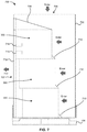
- FIG. 7 illustrates a side view of an example air filter assembly, in accordance with the disclosed technology.
- the present disclosure relates generally to filters and filter assemblies for filtering particulates from air and, more particularly, for filtering paint particulates from air.
- the disclosed technology can include an air filter box having a filter media pack and a filter housing.
- the filter media pack can be placed inside of the filter housing to form the air filter box and used to filter particulates from a mixture of air and particulates to create filtered air.
- the filter box can be used with an air filtration system of a paint booth to filter paint particulates that often result from paint overspray during the painting process.
- the mixture of air and particulates can be passed through the air filter by the air filtration system to create filtered air.
- more than one filter box can be assembled in a housing to form a filter assembly having multiple filter boxes.
- the disclosed technology can be used in residential air filtration or other industrial and manufacturing air filtration systems (e.g., air filtration for metal working, wood working, composites finishing, foundries, etc.) or any other type of air filtration system used to filter particles from the air.
- air filtration systems e.g., air filtration for metal working, wood working, composites finishing, foundries, etc.
- any other type of air filtration system used to filter particles from the air.
- Such implementations and applications are contemplated within the scope of the present disclosure. Accordingly, when the present disclosure is described in the context of being a filter and filter assembly for capturing paint overspray, it will be understood that other implementations can take the place of those referred to. Furthermore, when reference is made to air being the fluid that particulates are filtered from, it will be understood that other fluids can take the place of air depending on the particular application.
- the present disclosure includes filters and filter assemblies for capturing particulates from air and, more particularly, to capturing paint overspray commonly resulting from use of aerosol paints and paint spray guns.
- the disclosed technology can include a filter media pack 100 having a filter layer 102 .
- the filter layer 102 can be a continuous piece of filter material and be configured to be folded along its length to a more compact configuration.
- the filter media pack 100 can be folded to a compact configuration when shipped or stored and unfolded, or at least partially unfolded, to be deployed as an air filter.
- the filter layer 102 can be made from any suitable type of filter media that is capable of filtering particulates from air or other fluids.
- the filter layer 102 can be made from lofted or non-woven polyester, lofted or non-woven polypropylene, filament fiberglass, polyurethane foam, electrostatic polypropylene, shredded paper, cardboard, cotton, or any other suitable filter media for the particular application.
- the filter layer 102 can be configured to allow air (or other gases) to pass through the filter while particulates suspended in the air can be filtered from the air.
- the filter layer 102 can also be treated with a flame retarding agent, activated carbon, tackifier or other post-manufacturing treatment that can help to enhance the effectiveness and/or longevity of the filter layer 102 .
- the filter media pack 100 can include one or more seams 104 at various locations along the filter layer 102 .
- the seam 104 can be formed along an outer edge of the filter layer 102 and at locations where the filter layer 102 is likely to be bent either for storage or for use.
- the seam 104 can help to increase the durability of the filter layer 102 .
- the seam 104 can help to keep the filter layer 102 together when, for example, the filter layer is made from lofted polyester.
- the seam 104 can be formed using any suitable means of forming the seam 104 .
- the seam 104 can be formed by thermal bonding, stitching, glue, fasteners, or any other suitable manufacturing method of forming the seam 104 .
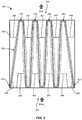
- FIG. 2A illustrates a top view of an example filter media pack 100 , in accordance with the disclosed technology.
- the filter media pack 100 can include multiple filter layers to increase the effectiveness of the filter media pack 100 .
- the filter media pack 100 can have a first filter layer 202 and a second filter layer 204 bonded together to form the filter media pack 100 .
- the filter media pack 100 can be made from multiple different types of filter media.
- the first filter layer 202 can be made from a lofted polyester having a first density while the second filter layer 204 can be made from a lofted polyester having a second density.
- the first filter layer 202 can be made from a lofted polyester while the second filter layer 204 can be made from fiberglass.
- the filter media pack 100 can be made from multiple layers of filter media being made from various materials and having various material properties to increase the effectiveness of the filter media pack 100 for the particular application.
- the filter media pack 100 can include a filter media support 206 that can be bonded between the first filter layer 202 and the second filter layer 204 .
- the filter media support 206 can be configured to provide support to the first filter layer 202 and the second filter layer 204 .
- the filter media support 206 can provide support and stability to the filter media pack 100 when the filter media pack 100 experiences a differential pressure caused by the air filtration system when the filter media pack 100 is used to filter particulates from air.
- the filter media support 206 can be made from supportive material such as cardboard, plastics, PVC, metals, composite materials, or any other suitable material for the application.
- the filter media support 206 can be installed between the first filter layer 202 and the second filter layer 204 along portions of the filter media pack 100 intended to remain linear while the filter media support 206 can be absent from portions of the filter media pack 100 intended to be bent.
- the filter media supports 206 can provide support to the filter media pack 100 along lengths of the filter media pack 100 that are likely to need the most support while also facilitating folding of the filter media pack 100 where the filter media supports 206 are absent.
- the filter media supports 206 can be made of a non-breathable material the filter media supports 206 can prevent a mixture of air and particulates from passing through the filter media pack 100 at locations where the filter media supports 206 are installed.
- the filter media supports 206 can channel or direct the flow of a mixture of air and particulates through the filter media pack 100 at the locations where the filter media support is absent.
- the filter media pack 100 depicted in FIG. 2A can permit the mixture of air and particulates to pass through the filter media pack 100 at the locations where the filter media support 206 is absent (e.g., at either end and each bend location of the filter media pack 100 ).
- the filter media pack 100 can be configured to channel the flow of air and particulates such that the filter media pack 100 collects or captures particulates without prematurely clogging.
- the filter media pack 100 can be configured with greater gaps between the filter media supports 206 at a back of the filter media pack 100 (nearer an outlet of the filter box described in greater detail herein) than gaps between the filter media supports 206 at the front of the filter media pack 100 (nearer an inlet of the filter box described in greater detail herein).
- the filter media pack 100 can be configured to channel or direct the flow of the air and particulates toward a back portion of the filter media pack 100 such that particulates are collected along the length of the filter media pack 100 rather than concentrated at a front portion of the filter media pack 100 which could lead to a premature clogging of the filter media pack 100 .
- FIGS. 2B and 2C illustrate side views of other example filter media supports 206 , in accordance with the disclosed technology.
- the filter media support 206 can include apertures 208 that can help to channel a mixture of air and particulates through the filter media pack 100 at the locations of the apertures 208 .
- the filter media supports 206 can include slots 210 that can help to channel a mixture of air and particulates through the filter media pack at the locations of the slots 210 .
- the filter media supports 206 can be further configured such that a greater concentration of the apertures 208 or the slots 210 can be positioned nearer a back portion of the filter media pack 100 (or nearer an exit of the filter box described further herein) such that a greater portion of the mixture of air and particulates is directed along the length of the filter media pack 100 rather than concentrated at a front portion of the filter media pack 100 which could lead to a premature clogging of the filter media pack 100 .
- the filter media supports 206 can have a greater concentration of the apertures 208 or the slots 210 near the front or middle portions of the filter media pack.
- FIG. 3 illustrates a top view of an example filter box 300 , in accordance with the disclosed technology.
- the filter box 300 depicted in FIG. 3 is shown with a top of the filter box 300 opened such that the internal portions of the filter box 300 are visible.
- the filter housing 302 can receive and support the filter media pack 100 to form the filter box 300 .
- FIG. 3 illustrates a top view of an example filter box 300 , in accordance with the disclosed technology.
- FIG. 3 illustrates a top view of an example filter box 300 , in accordance with the disclosed technology.
- the filter box 300 depicted in FIG. 3 is shown with a top of the filter box 300
- the air and particulate mix can be configured to enter a first side of the filter box 300 (e.g., at an inlet 301 ) and exit the filter box 300 at an opposite side of the filter box 300 (e.g., at an outlet 303 ).
- the particulates can be captured by, or adhere to, the filter media pack 100 such that filtered air can be released at the outlet 303 .
- the filtered air can be released to the atmosphere, recirculated back through the paint booth, or directed by the air filtration system through further filtering before being released to the atmosphere or recirculated back through the paint booth.
- the filter housing 302 can be configured to have approximately equal spacing between the ends of the filter media pack 100 and each of the bends of the filter media pack 100 .
- the filter media pack 100 can be shaped in an alternating “V” wedge configuration (e.g., a zig-zag) inside of the filter housing 302 .
- the filter media pack 100 can be formed in many different configurations to fit the particular application.
- the filter media pack 100 can be folded over on itself during storage and shipment and then extended outward like an accordion when deployed in the filter housing 302 forming the alternating “V” wedge configuration.
- the filter media pack 100 can be inserted into the filter housing 302 in the alternating “V” wedge configuration such that the widest part (i.e., the top portion of the “V”) faces the entering air side.
- the filter media pack 100 can be sized slightly larger than the internal spacing of the filter housing 302 such that the filter media pack 100 is compressed or bent by the filter housing 302 to form a friction fit gasket 310 . In this way, the filter media pack 100 can form a tight seal along each of the edges of the filter media pack 100 that come into contact with the filter housing 302 .
- this can include the top and bottom portions of the filter media pack 100 contacting a top and bottom portion of the filter housing 302 (i.e., the portions of the filter media pack 100 and filter housing 302 that are positionally located into and out of the plane (or page) of FIG. 3 ) as well as the portions of the filter media pack 100 that contact a front and back portion of the filter housing 302 (i.e., the upper and lower portions of the filter media pack 100 and the filter housing 302 as depicted in FIG. 3 ).
- the filter housing 302 can include one or more portions that are configured to support and align the filter media pack 100 inside of the filter housing 302 .
- the filter housing 302 can include inlet guide fingers 304 , inlet support tabs 306 , outlet guide fingers 307 , and outlet support tabs 308 (collectively, “the Support Tabs”).
- the Support Tabs can each be part of the material that makes up the filter housing 302 and can be configured to fold inwardly from an outer surface of the filter housing 302 .
- the Support Tabs can each be sized and positioned such that each of the Support Tabs contact an edge of the filter media pack 100 and help to support the filter media pack 100 when a force is applied to the filter media pack 100 (e.g., when a pressure differential is applied to the filter media pack 100 from an air filtration system to cause the mixture of air and particulates to pass through the filter media pack 100 ).
- the Support Tabs can be configured to prevent movement of the filter media pack 100 when a force is applied to the filter media pack 100 and ensure the mixture of air and particulates passes through the filter media pack 100 rather than around it.
- the inlet guide fingers 304 can be sized and positioned such that the inlet guide fingers 304 contact an edge of a front surface (i.e., the surface facing the inlet 301 ) of the filter media pack 100 near bends in the middle portion of the filter media pack and help to support the filter media pack 100 when a force is applied to the filter media pack 100 .
- the inlet guide fingers 304 can be sized such that the filter media pack 100 can contact the inlet guide fingers 304 along an edge of the inlet guide fingers 304 .
- the inlet guide fingers 304 can be sized and positioned to ensure the filter media pack 100 is aligned or positioned properly within the filter housing 302 .
- the inlet support tabs 306 can be sized and positioned such that the inlet support tabs 306 can fold inwardly and contact the filter media pack 100 near an end of the filter media pack 100 .
- the filter media pack 100 and the filter housing 302 can be configured such that the ends of the filter media pack 100 can be tucked behind an edge of the filter housing 302 proximate the inlet 301 and the inlet support tabs 306 can help to keep the ends of the filter media pack 100 tucked behind the edge of the filter housing 302 .
- the inlet support tabs 306 can help to ensure the filter media pack 100 is pressed against an edge of the filter housing 302 such that the filter media pack 100 remains in place and the mixture of air and particulates is prevented from escaping around the filter media pack 100 .
- the outlet guide fingers 307 can be sized and positioned such that the outlet guide fingers 307 contact an edge of a rear surface (i.e., the surface facing the outlet 303 ) of the filter media pack 100 near bends in the middle portion of the filter media pack and help to support the filter media pack 100 when a force is applied to the filter media pack 100 .
- the outlet guide fingers 307 can be sized such that the filter media pack 100 can contact the outlet guide fingers 307 along a length of the outlet guide fingers 307 .
- the outlet guide fingers 307 can be sized and positioned to ensure the filter media pack 100 is aligned or positioned properly within the filter housing 302 .
- the outlet support tabs 308 can be sized and positioned such that the outlet support tabs 308 can fold inwardly and contact the rear surface (i.e., the surface facing the outlet 303 ) of the filter media pack 100 near outer ends of bends in the middle portion of the filter media pack 100 .
- the outlet support tabs 308 can help to support the filter media pack 100 when a force is applied to the filter media pack 100 .
- FIG. 4A illustrates a front perspective view of the filter box 300 , in accordance with the disclosed technology.
- the filter housing 302 can enclose the filter media pack 100 to form the filter box 300 .
- the inlet 301 can be formed from material forming a wall of the filter box 300 and can be sized and positioned to permit a mixture of air and particulates to pass through the filter box 300 to create filtered air by passing through the filter media pack 100 .
- the inlet guide fingers 304 can include inlet guide finger perforations 404 that can facilitate the inlet guide fingers 304 being folded inwardly into the filter housing 302 to form the inlet 301 and position the inlet guide fingers 304 to engage the filter media pack 100 .
- the inlet support tabs 306 can include inlet support tab perforations 406 that can facilitate the inlet support tabs 306 being folded inwardly into the filter housing 302 to form the inlet 301 and position the inlet support tabs 306 to engage the filter media pack 100 .
- the inlet guide finger perforations 404 and the inlet support tab perforations 406 can be sized such that a user can push the inlet guide fingers 304 and the inlet support tabs 306 inwardly without tearing the filter housing 302 .
- FIG. 4B illustrates a rear perspective view of the filter box 300 , in accordance with the disclosed technology.
- the filter housing 302 can enclose the filter media pack 100 to form the filter box 300 .
- the outlet 303 can be formed from material forming a wall of the filter box 300 and can be sized and positioned to permit a mixture of air and particulates to pass through the filter box 300 to create filtered air by passing through the filter media pack 100 .
- the outlet guide fingers 307 can include outlet guide finger perforations 407 that can facilitate the outlet guide fingers 307 being folded inwardly into the filter housing 302 to form the outlet 303 and position the outlet guide fingers 307 to engage the filter media pack 100 .
- the outlet support tabs 308 can include outlet support tab perforations 408 that can facilitate the outlet support tabs 308 being folded inwardly into the filter housing 302 to form the outlet 303 and position the outlet support tabs 308 to engage the filter media pack 100 .
- the outlet guide finger perforations 407 and the outlet support tab perforations 408 can be sized such that a user can push the outlet guide fingers 307 and the outlet support tabs 308 inwardly without tearing the filter housing 302 .
- FIG. 5A illustrates a front view of a filter box 300 , in accordance with the disclosed technology.
- the filter box 300 illustrated in FIG. 5A depicts the inlet guide fingers 304 and the inlet support tabs 306 before the inlet guide fingers 304 and the inlet support tabs 306 are pushed inwardly to form the inlet 301 .
- the inlet guide fingers 304 can each include at least two sets of inlet guide finger perforations 404 to facilitate the inlet guide fingers 304 being pushed inwardly to form the inlet 301 .
- the inlet guide fingers 304 can be better able to engage the filter media pack 100 while allowing greater spacing for the inlet 301 .
- the inlet support tabs 306 can include at least one set of inlet support tab perforations 406 such that the inlet support tabs 306 can be pushed inwardly and engage the filter media pack 100 near the ends of the filter media pack 100 to help keep the filter media pack 100 in place.
- FIG. 5B illustrates a front view of a filter box 300 , in accordance with the disclosed technology. Similar to FIG. 5A , the filter box 300 illustrated in FIG. 5B depicts the outlet guide fingers 307 and the outlet support tabs 308 before the outlet guide fingers 307 and the outlet support tabs 308 are pushed inwardly to form the inlet 301 . As depicted, the outlet guide fingers 307 can each include at least two sets of outlet guide finger perforations 407 to facilitate the outlet guide fingers 307 being pushed inwardly to form the outlet 303 . By including at least two sets of outlet guide finger perforations 407 , the outlet guide fingers 307 can be better able to engage the filter media pack 100 while allowing greater spacing for the outlet 303 .
- the outlet support tabs 308 can include outlet support tab extensions 508 that can be folded inwardly and horizontally to engage the filter media pack 100 .
- the outlet support tab extensions 508 can be formed by the outlet support tabs 308 including at least three sets of outlet support tab perforations 408 —one of which can facilitate the outlet support tabs 308 being pushed inwardly into the filter box 300 while the other two outlet support tab perforations 408 can facilitate the outlet support tab extensions 508 being oriented horizontally to engage and help to support the filter media pack 100 .
- FIG. 6 illustrates a top view of an example filter housing 302 in an unassembled state, in accordance with the disclosed technology.
- the filter housing 302 can be made from a single piece of material.
- the filter housing 302 can be made from a single piece of cardboard and be configured such that the filter housing 302 can be folded from an unassembled state (as depicted in FIG. 6 ) to the assembled state (as depicted in FIGS. 4A-5B ).
- the filter housing 302 can be configured to be generally flat when in an unassembled state which can require less space when the filter housing 302 is stored or shipped.
- the filter housing 302 is made from a single piece of cardboard, the filter housing 302 can be made using a cutting die, a cutting machine, or other similar manufacturing processes for manufacturing cardboard boxes. Alternatively, the filter housing 302 can be made from multiple pieces of material affixed to each other to form the filter housing 302 .
- the filter box 300 can be installed in a location where a mixture of air and particulates is directed from a paint booth to ensure particulates in the air are filtered from the air prior to the air being released to the environment or recycled back through the paint booth.
- a single filter box 300 can be used for smaller filtration applications and multiple filter boxes 300 can be used for larger filtration applications.
- the size and shape of the filter box 300 can be varied as appropriate for the particular application. For example, the filter box 300 can be smaller for air filtration systems having a relatively low filtration capacity and larger for air filtration systems having a relatively high filtration capacity.
- more than one filter box 300 can be assembled together to form a filter assembly 700 as depicted in FIG. 7 .
- the filter assembly 700 can be installed in an air filtration system for filtering particulates from a mixture of particulates and air.
- the filter assembly 700 can be formed by multiple filter boxes 300 being placed within a filter assembly housing 702 to create a filter assembly 700 to be installed in an air filtration system.
- FIG. 7 As a specific example, and as depicted in FIG.
- multiple filter boxes 300 can be stacked vertically within a filter assembly housing 702 configured to direct air from the filter assembly inlet 706 located at a top portion of the filter assembly housing 702 , through the filter boxes 300 , and out a filter assembly outlet 707 located at a side portion of the filter assembly housing 702 .
- This configuration can be, for example, installed in air filtration systems that utilize a downdraft in a paint booth to capture particulates.
- the filter assembly 700 can be sized to fit existing air filtration systems such that a user can simply assemble the filter assembly 700 , remove a used filter assembly 700 , and replace the used filter assembly 700 with the newly assembled filter assembly 700 .
- replacing used filter assemblies 700 with new filter assemblies 700 can be accomplished when the air filtration system is shut down or while the air filtration system is still in operation.
- the filter assembly housing 702 for holding the multiple filter boxes 300 can be made from the same material used to make the supportive exterior of the filter box (e.g., cardboard, plastic, PVC, metals, composite materials, or any other suitable material for the application).
- the filter assembly housing 702 can be configured to form a nearly air-tight barrier around the filter boxes 300 such that the mixture of air and particulates is directed through the filter boxes 300 and not around them.
- the filter assembly housing 702 can be configured to have spacers and supports in predetermined locations such that the filter assembly housing 702 is able to help ensure the filter boxes 300 are properly spaced and supported when installed in the filter assembly housing 702 .
- the filter assembly housing 702 can also include reinforcing material located where the filter assembly housing 702 is likely to be lifted and secured in the air filtration system.
- the filter assembly housing 702 can have reinforcing tabs 714 located where a restraint device (e.g., pneumatic clamp, hydraulic clamp, manual clamp, or other device configured to keep the filter assembly 700 in place) is likely to grip the filter assembly housing 702 to hold the filter assembly 700 in place.
- a restraint device e.g., pneumatic clamp, hydraulic clamp, manual clamp, or other device configured to keep the filter assembly 700 in place
- the filter assembly housing 702 can be mounted on a base structure 704 that can be used to lift and move the filter assembly 700 with, for example, a pallet jack or forklift.
- the base structure 704 can be a pallet, a wooden base, a reinforced cardboard base, a plastic base, or any other suitable type of base structure for the application.
- the filter boxes 300 are installed vertically together into a filter assembly housing 702 to form a filter assembly 700 , the filter boxes can be offset horizontally, as depicted in FIG. 7 , to facilitate improved air flow during use.
- the filter box 300 nearest the filter assembly inlet 706 is likely to be the first to clog during use because a greater number of particulates will initially be directed through the filter box 300 nearest the filter assembly inlet 706 .
- the particulates will build up and begin to restrict air flow through the filter box 300 .
- the passage between the filter box 300 and the filter assembly housing 702 can eventually be restricted and air flow reduced.
- the filter boxes 300 horizontally such that the largest clearance between the filter box 300 and the filter assembly housing 702 is nearest the filter assembly inlet 706 and the smallest clearance between the filter box 300 and the filter assembly housing 702 is farthest from the filter assembly inlet 706 , the mixture of air and particulates is able to reach the farthest filter box 300 from the filter assembly inlet 706 as the other filter boxes 300 become clogged during use.
- a filter box 300 further from the inlet 706 can clog during use before the other filter boxes 300 . In this situation, particulates begin to collect on the remaining filter boxes 300 as the air and particulates are directed around the clogged filter box 300 and toward remaining unclogged filter boxes 300 .
- the filter assembly 700 can include a sloped edge 708 at the filter assembly inlet 706 air deflectors 710 between each filter box 300 to help improve air flow through the filter assembly 700 .
- the inlet can include a sloped edge 708 to help direct the air and particulates through the filter assembly inlet 706 and toward the filter boxes 300 as the mixture of air and particulates enter the filter assembly 700 .
- the sloped edge 708 near the filter assembly inlet 706 can be sized and shaped as suitable for the particular application. Furthermore, as depicted in FIG.
- the filter assembly 700 can include air deflectors 710 between each filter box 300 to eliminate a flat edge of a top portion of a filter box 300 resulting from the offset between the filter boxes 300 that could otherwise cause a greater pressure differential as air is directed through the filter assembly 700 .
- the sloped edge 708 and the air deflectors 710 can be made from the same material as the filter assembly housing 702 (e.g., cardboard, plastic, PVC, metals, composite materials, or any other suitable material for the application) or the sloped edge 708 and the air deflectors 710 can be made from material that is different than the filter assembly housing 702 depending on the application.
- the filter assembly 700 can further include a supplemental filter 712 that can be installed proximate the filter assembly outlet 707 to filter particulates that may escape past the filter boxes 300 .
- the supplemental filter 712 can be a sheet of filter media stretched across the filter assembly outlet 707 .
- the supplemental filter 712 can be made from the same material as the filter layer 102 of the supplemental filter 712 can be made from material that is different than the filter layer 102 .
- the filter assembly 700 just described and depicted in FIG. 7 is offered only for illustrative purposes and should not be construed as limiting.
- the filter boxes 300 can be stacked horizontally (side-by-side) and placed in a filter assembly housing 702 for applications where it would be advantageous to filter the mixture of air and particulates that enters and exits the filter assembly 700 horizontally.
- the filter boxes 300 can be positioned vertically (installed with the inlet 301 facing upwards and the outlet 303 downwards) for applications where it would be advantageous to filter a mixture of air and particulates that enters and exits the filter assembly 700 vertically.
- the filter boxes 300 can be installed in series (one filter box 300 placed directly after another filter box 300 ) for applications where it would be advantageous to provide additional filtering.
- the disclosed technology can comprise many different configurations to fit a particular application. In each configuration, the many of the features previously described can be included such as each filter box 300 being offset from an adjacent filter box 300 , a sloped edge 708 , air deflectors 710 , etc.
- the size and shape of the filter assembly 700 can be varied as appropriate for the particular application.
- the filter assembly 700 can be smaller for air filtration systems having a relatively low filtration capacity and larger for air filtration systems having a relatively high filtration capacity.
- the filter assembly 700 can have dimensions of 85 inches tall, 32.5 inches wide, and 48.375 inches depth.
Landscapes
- Chemical & Material Sciences (AREA)
- Chemical Kinetics & Catalysis (AREA)
- Filtering Of Dispersed Particles In Gases (AREA)
Abstract
Description
- This application claims priority to U.S. Provisional Patent Application No. 62/938,165 filed 20 Nov. 2019 and U.S. Provisional Patent Application No. 63/032,123 filed 29 May 2020, the contents of which are incorporated herein by reference in their entirety as if set forth verbatim.
- The present disclosure relates generally air filters and filter assemblies for filtering particulates from air and, more particularly, for filtering paint particulates from air.
- For centuries paint has been used to protect and beautify materials. Traditionally, paint is applied to a surface using a paintbrush, roller, or other device which soaks up the paint and then applies it to the surface by physical contact. However, a more recent method of painting utilizes compressed gasses (e.g., compressed air, propane, butane, isobutane, methyl ethyl, nitrous oxide, or carbon dioxide, etc.) to create an aerosol mixture of paint particles and gas to apply paint to a surface. The resultant aerosol mixture is propelled from a spray device and the paint particles are applied to the surface in a constant stream allowing the user to rapidly apply paint to a surface. Although this form of painting may save time, and potentially create better finishes, there are dangers associated with using this painting method including inhaling toxic fumes and paint particulates.
- To reduce the danger of inhaling toxic fumes and paint particulates, various methods of filtering out the toxic particulates from the air have been developed. For example, air filtration systems help to reduce harmful particulates in the air. Furthermore, designated paint booths can be used to isolate the area where paint fumes may exist from other areas where one would expect clean air. Air filtration systems are used to provide a fresh supply of breathable air to the painters inside the paint booth and filter out particulates from air exiting the paint booth.
- To capture the harmful fumes and particulates exiting a paint booth, various types of filters are used. One type of filter comprises a rectangular (e.g., a square) box-shaped filter which has filter media placed inside of the filter box to capture paint particulates and allow filtered air to exit to the atmosphere or be recirculated through the air filtration system. The box filter can be disposed once it has reached the end of its usable life. Many current designs of box filters utilize a series of cardboard baffles or shredded paper for filter media. However, these designs tend to prematurely clog up the entrance of the filter rather than utilize the entire filter media available leading to an ineffective use of the filter media. Furthermore, these designs are cumbersome to assemble causing the user frustration and increasing the margin for error in the assembly of the filter. Therefore, the present invention is directed to an improved paint box filter using alternative filter media which can effectively capture particulates and reduce the amount of time required to assemble the paint filter.
- The disclosed technology relates generally to filters and filter assemblies for capturing paint overspray.
- The disclosed technology can include an air filter box for filtering particulates from a mixture of air and particulates. The air filter box can include a filter media pack configured to receive a mixture of air and particulates and filter at least a portion of the particulates from the mixture of air and particulates to create filtered air. The filter media pack can include a filter layer configured to filter at least a portion of the particulates from the mixture of air and particulates and a plurality of filter media supports configured to provide support to the filter layer.
- The filter box can also include a filter housing configured to receive and support the filter media pack. The filter housing can include an inlet configured to receive the mixture of air and particulates, an outlet configured to receive the filtered air from the filter media pack and release the filtered air out the outlet, and a plurality of support tabs configured to align and support the filter media pack inside of the filter housing. The filter media pack can be configured to be folded and placed inside of the filter housing for cooperative engagement with the support tabs. Furthermore, the air filter box can be configured to channel the mixture of air and particulates from the inlet, through the filter media pack, and out the outlet to create the filtered air.
- The filter layer can be a first filter layer configured to filter at least a first portion of the particulates from the mixture of air and particulates and the air filter box can further include a second filter layer affixed to the first filter layer that can be configured to filter at least a second portion of the particulates from the mixture of air and particulates. The first filter layer can be thermally bonded to the second filter layer.
- The plurality of filter media supports can be located between the first filter layer and the second filter layer. The plurality of filter media supports can also include a plurality of perforations configured to channel the mixture of air and particulates through the first filter layer and the second filter layer at the plurality of perforations to create the filtered air. Alternatively, or in addition, the plurality of filter media supports can form a gap between adjoining filter media supports such that the plurality of filter media supports channel the mixture of air and particulates through the first filter layer and the second filter layer at the gap to create the filtered air.
- The filter media pack can be configured to form a friction fit seal at an interface between the filter media pack and the filter housing. The friction fit seal can be configured to prevent the mixture of air and particulates from being directed around an outer edge of the filter media pack.
- The filter housing can be configured to be folded from a relatively flat state to a deployed state. The plurality of support tabs can include inlet guide fingers configured to support and align the filter media pack inside of the filter housing. The inlet guide fingers can be configured to fold inwardly from a top and bottom of a front outer wall of the filter housing to, at least partially, form the inlet. The plurality of support tabs can include inlet support tabs configured to align and support the filter media pack inside of the filter housing. The inlet support tabs can be configured to fold inwardly from a side of a front outer wall of the filter housing to, at least partially, form the inlet. The plurality of support tabs can include outlet guide fingers configured to support and align the filter media pack inside of the filter housing. The outlet guide fingers can be configured to fold inwardly from a top and bottom of a rear outer wall of the filter housing to, at least partially, form the outlet. The plurality of support tabs can include outlet support tabs configured to support the filter media pack inside of the filter housing. The outlet support tabs can be configured to fold inwardly from a side of a rear outer wall of the filter housing to, at least partially, form the outlet. The filter layer can include lofted polyester.
- The disclosed technology can include an air filter assembly. The air filter assembly can include a plurality of air filter boxes. Each air filter box can include a filter media pack configured to receive a mixture of air and particulates and filter at least a portion of the particulates from the mixture of air and particulates to create filtered air. The filter media pack can include a filter layer configured to filter at least a portion of the particulates from the mixture of air and particulates. The filter media pack can include a plurality of filter media supports configured to provide support to the filter layer.
- Each filter box can further include a filter housing configured to receive and support the filter media pack. The filter housing can include an inlet configured to receive the mixture of air and particulates and an outlet configured to receive the filtered air from the filter media pack and release the filtered air out the outlet. The filter media pack can be configured to be folded and placed inside of the filter housing. The air filter box can be configured to channel the mixture of air and particulates from the inlet, through the filter media pack, and out the outlet to create the filtered air.
- The air filter assembly can include a filter assembly housing configured to receive and support the plurality of air filter boxes. The filter assembly housing can include an air filter assembly inlet configured to receive the mixture of air and particulates and channel the mixture of air and particulates toward the plurality of air filter boxes. The filter assembly housing can include an air filter assembly outlet configured to receive the filtered air from the plurality of air filter boxes and channel the filtered air out the air filter assembly outlet. The filter assembly housing can be configured to channel the mixture of air and particulates through the plurality of the air filter boxes simultaneously.
- The air filter assembly can include a first air filter box that can be offset a distance from a second air filter box such that a distance between the inlet of the first air filter box and a wall of the filter assembly housing is greater than a distance between the inlet of the second air filter box and the wall of the filter assembly housing. The first air filter box can be nearer the filter assembly inlet than the second air filter box.
- The air filter assembly inlet can include a sloped edged configured to channel the mixture of air and particulates toward the plurality of air filter boxes. The air filter assembly can include one or more air deflectors configured to channel the mixture of air and particulates through the plurality of air filter boxes. The air filter assembly can include reinforcing tabs configured to receive a restraint device of an air filtration system. The air filter assembly inlet can be located proximate a top surface of the air filter assembly and the air filter assembly outlet can be located proximate a back surface of the air filter assembly.
- Additional features, functionalities, and applications of the disclosed technology are discussed herein in more detail.
- The accompanying drawings, which are incorporated in and constitute a part of this specification, illustrate multiple examples of the presently disclosed subject matter and serve to explain the principles of the presently disclosed subject matter. The drawings are not intended to limit the scope of the presently disclosed subject matter in any manner.
-
FIG. 1 illustrates a top perspective view of an example filter media pack, in accordance with the disclosed technology. -
FIG. 2A illustrates a top view of an example filter media pack, in accordance with the disclosed technology. -
FIG. 2B illustrates a side view of an example filter media support, in accordance with the disclosed technology. -
FIG. 2C illustrates a side view of an example filter media support, in accordance with the disclosed technology. -
FIG. 3 illustrates a top view of an example filter box, in accordance with the disclosed technology. -
FIG. 4A illustrates a front perspective view of an example filter box, in accordance with the disclosed technology. -
FIG. 4B illustrates a rear perspective view of an example filter box, in accordance with the disclosed technology. -
FIG. 5A illustrates a front view of an example filter box, in accordance with the disclosed technology. -
FIG. 5B illustrates a rear view of an example filter box, in accordance with the disclosed technology. -
FIG. 6 illustrates a top view of a filter housing in an unassembled state, in accordance with the disclosed technology. -
FIG. 7 illustrates a side view of an example air filter assembly, in accordance with the disclosed technology. - The present disclosure relates generally to filters and filter assemblies for filtering particulates from air and, more particularly, for filtering paint particulates from air. The disclosed technology, for example, can include an air filter box having a filter media pack and a filter housing. The filter media pack can be placed inside of the filter housing to form the air filter box and used to filter particulates from a mixture of air and particulates to create filtered air. For example, the filter box can be used with an air filtration system of a paint booth to filter paint particulates that often result from paint overspray during the painting process. The mixture of air and particulates can be passed through the air filter by the air filtration system to create filtered air. In some examples, more than one filter box can be assembled in a housing to form a filter assembly having multiple filter boxes.
- Although certain examples of the disclosed technology are explained in detail, it is to be understood that other examples, embodiments, and implementations of the disclosed technology are contemplated. Accordingly, it is not intended that the disclosed technology is limited in its scope to the details of construction and arrangement of components set forth in the following description or illustrated in the drawings. The disclosed technology can be implemented in a variety of examples and can be practiced or carried out in various ways. In particular, the presently disclosed subject matter is described in the context of being a filter and filter assembly for filtering paint overspray particulates from air. The present disclosure, however, is not so limited, and can be applicable in other air filtering contexts. The present disclosure, for example and not limitation, can include filters and filter assemblies used in other types of air filtration systems. For example, and not limitation, the disclosed technology can be used in residential air filtration or other industrial and manufacturing air filtration systems (e.g., air filtration for metal working, wood working, composites finishing, foundries, etc.) or any other type of air filtration system used to filter particles from the air. Such implementations and applications are contemplated within the scope of the present disclosure. Accordingly, when the present disclosure is described in the context of being a filter and filter assembly for capturing paint overspray, it will be understood that other implementations can take the place of those referred to. Furthermore, when reference is made to air being the fluid that particulates are filtered from, it will be understood that other fluids can take the place of air depending on the particular application.
- It should also be noted that, as used in the specification and the appended claims, the singular forms “a,” “an,” and “the” include plural references unless the context clearly dictates otherwise. References to a composition containing “a” constituent is intended to include other constituents in addition to the one named.
- Also, in describing the examples, terminology will be resorted to for the sake of clarity. It is intended that each term contemplates its broadest meaning as understood by those skilled in the art and includes all technical equivalents which operate in a similar manner to accomplish a similar purpose.
- Herein, the use of terms such as “having,” “has,” “including,” or “includes” are open-ended and are intended to have the same meaning as terms such as “comprising” or “comprises” and not preclude the presence of other structure, material, or acts. Similarly, though the use of terms such as “can” or “may” are intended to be open-ended and to reflect that structure, material, or acts are not necessary, the failure to use such terms is not intended to reflect that structure, material, or acts are essential. To the extent that structure, material, or acts are presently considered to be essential, they are identified as such.
- The components described hereinafter as making up various elements of the disclosed technology are intended to be illustrative and not restrictive. Many suitable components that would perform the same or similar functions as the components described herein are intended to be embraced within the scope of the disclosed technology. Such other components not described herein can include, but are not limited to, for example, similar components that are developed after development of the presently disclosed subject matter.
- Referring now to the drawings, in which like numerals represent like elements, examples of the present disclosure are herein described. As will be described in greater detail, the present disclosure includes filters and filter assemblies for capturing particulates from air and, more particularly, to capturing paint overspray commonly resulting from use of aerosol paints and paint spray guns.
- As depicted in
FIG. 1 , the disclosed technology can include afilter media pack 100 having afilter layer 102. Thefilter layer 102 can be a continuous piece of filter material and be configured to be folded along its length to a more compact configuration. For example, thefilter media pack 100 can be folded to a compact configuration when shipped or stored and unfolded, or at least partially unfolded, to be deployed as an air filter. Thefilter layer 102 can be made from any suitable type of filter media that is capable of filtering particulates from air or other fluids. For example, thefilter layer 102 can be made from lofted or non-woven polyester, lofted or non-woven polypropylene, filament fiberglass, polyurethane foam, electrostatic polypropylene, shredded paper, cardboard, cotton, or any other suitable filter media for the particular application. No matter the material that thefilter layer 102 is made from, thefilter layer 102 can be configured to allow air (or other gases) to pass through the filter while particulates suspended in the air can be filtered from the air. Furthermore, thefilter layer 102 can also be treated with a flame retarding agent, activated carbon, tackifier or other post-manufacturing treatment that can help to enhance the effectiveness and/or longevity of thefilter layer 102. - The
filter media pack 100 can include one ormore seams 104 at various locations along thefilter layer 102. Theseam 104, for example, can be formed along an outer edge of thefilter layer 102 and at locations where thefilter layer 102 is likely to be bent either for storage or for use. Theseam 104 can help to increase the durability of thefilter layer 102. For example, if theseam 104 is formed along an outer edge of thefilter layer 102, theseam 104 can help to keep thefilter layer 102 together when, for example, the filter layer is made from lofted polyester. Theseam 104 can be formed using any suitable means of forming theseam 104. For example, theseam 104 can be formed by thermal bonding, stitching, glue, fasteners, or any other suitable manufacturing method of forming theseam 104. -
FIG. 2A illustrates a top view of an examplefilter media pack 100, in accordance with the disclosed technology. As depicted inFIG. 1 , in some examples, thefilter media pack 100 can include multiple filter layers to increase the effectiveness of thefilter media pack 100. For example, thefilter media pack 100 can have afirst filter layer 202 and asecond filter layer 204 bonded together to form thefilter media pack 100. If thefilter media pack 100 has more than a single filter layer, thefilter media pack 100 can be made from multiple different types of filter media. For example, thefirst filter layer 202 can be made from a lofted polyester having a first density while thesecond filter layer 204 can be made from a lofted polyester having a second density. In other examples, thefirst filter layer 202 can be made from a lofted polyester while thesecond filter layer 204 can be made from fiberglass. As will be appreciated by one of skill in the part, thefilter media pack 100 can be made from multiple layers of filter media being made from various materials and having various material properties to increase the effectiveness of thefilter media pack 100 for the particular application. - As depicted in
FIG. 2A , thefilter media pack 100 can include afilter media support 206 that can be bonded between thefirst filter layer 202 and thesecond filter layer 204. Thefilter media support 206 can be configured to provide support to thefirst filter layer 202 and thesecond filter layer 204. For example, thefilter media support 206 can provide support and stability to thefilter media pack 100 when thefilter media pack 100 experiences a differential pressure caused by the air filtration system when thefilter media pack 100 is used to filter particulates from air. Thefilter media support 206 can be made from supportive material such as cardboard, plastics, PVC, metals, composite materials, or any other suitable material for the application. - In some examples, and as depicted in
FIG. 2A , thefilter media support 206 can be installed between thefirst filter layer 202 and thesecond filter layer 204 along portions of thefilter media pack 100 intended to remain linear while thefilter media support 206 can be absent from portions of thefilter media pack 100 intended to be bent. By doing so, the filter media supports 206 can provide support to thefilter media pack 100 along lengths of thefilter media pack 100 that are likely to need the most support while also facilitating folding of thefilter media pack 100 where the filter media supports 206 are absent. Additionally, because the filter media supports 206 can be made of a non-breathable material the filter media supports 206 can prevent a mixture of air and particulates from passing through thefilter media pack 100 at locations where the filter media supports 206 are installed. Therefore, by not installing filter media supports 206 at various locations of thefilter media pack 100, the filter media supports 206 can channel or direct the flow of a mixture of air and particulates through thefilter media pack 100 at the locations where the filter media support is absent. For example, thefilter media pack 100 depicted inFIG. 2A can permit the mixture of air and particulates to pass through thefilter media pack 100 at the locations where thefilter media support 206 is absent (e.g., at either end and each bend location of the filter media pack 100). As will be appreciated by one of skill in the art, by causing the mixture of air and particulates to pass through thefilter media pack 100 at specific locations, thefilter media pack 100 can be configured to channel the flow of air and particulates such that thefilter media pack 100 collects or captures particulates without prematurely clogging. For example, thefilter media pack 100 can be configured with greater gaps between the filter media supports 206 at a back of the filter media pack 100 (nearer an outlet of the filter box described in greater detail herein) than gaps between the filter media supports 206 at the front of the filter media pack 100 (nearer an inlet of the filter box described in greater detail herein). In this way, thefilter media pack 100 can be configured to channel or direct the flow of the air and particulates toward a back portion of thefilter media pack 100 such that particulates are collected along the length of thefilter media pack 100 rather than concentrated at a front portion of thefilter media pack 100 which could lead to a premature clogging of thefilter media pack 100. -
FIGS. 2B and 2C illustrate side views of other example filter media supports 206, in accordance with the disclosed technology. As depicted inFIG. 2B , thefilter media support 206 can includeapertures 208 that can help to channel a mixture of air and particulates through thefilter media pack 100 at the locations of theapertures 208. Similarly, as depicted inFIG. 2C , the filter media supports 206 can includeslots 210 that can help to channel a mixture of air and particulates through the filter media pack at the locations of theslots 210. The filter media supports 206 can be further configured such that a greater concentration of theapertures 208 or theslots 210 can be positioned nearer a back portion of the filter media pack 100 (or nearer an exit of the filter box described further herein) such that a greater portion of the mixture of air and particulates is directed along the length of thefilter media pack 100 rather than concentrated at a front portion of thefilter media pack 100 which could lead to a premature clogging of thefilter media pack 100. Alternatively, if it is desirable to collect a greater amount of the particulates nearer a front portion of thefilter media pack 100, or a middle portion of thefilter media pack 100, the filter media supports 206 can have a greater concentration of theapertures 208 or theslots 210 near the front or middle portions of the filter media pack. - The
filter media pack 100 can be inserted into afilter housing 302 as depicted inFIG. 3 to form afilter box 300.FIG. 3 illustrates a top view of anexample filter box 300, in accordance with the disclosed technology. Thefilter box 300 depicted inFIG. 3 is shown with a top of thefilter box 300 opened such that the internal portions of thefilter box 300 are visible. As depicted inFIG. 3 , thefilter housing 302 can receive and support thefilter media pack 100 to form thefilter box 300. Furthermore, as depicted inFIG. 3 , the air and particulate mix can be configured to enter a first side of the filter box 300 (e.g., at an inlet 301) and exit thefilter box 300 at an opposite side of the filter box 300 (e.g., at an outlet 303). As the air and particulate mix passes through thefilter media pack 100, the particulates can be captured by, or adhere to, thefilter media pack 100 such that filtered air can be released at theoutlet 303. The filtered air can be released to the atmosphere, recirculated back through the paint booth, or directed by the air filtration system through further filtering before being released to the atmosphere or recirculated back through the paint booth. Although depicted as having greater spaces between ends of thefilter media pack 100 and a nearest bend of thefilter media pack 100 than neighboring bends of the filter media pack, thefilter housing 302 can be configured to have approximately equal spacing between the ends of thefilter media pack 100 and each of the bends of thefilter media pack 100. - The
filter media pack 100 can be shaped in an alternating “V” wedge configuration (e.g., a zig-zag) inside of thefilter housing 302. However, thefilter media pack 100 can be formed in many different configurations to fit the particular application. As a non-limiting example, thefilter media pack 100 can be folded over on itself during storage and shipment and then extended outward like an accordion when deployed in thefilter housing 302 forming the alternating “V” wedge configuration. In some examples, thefilter media pack 100 can be inserted into thefilter housing 302 in the alternating “V” wedge configuration such that the widest part (i.e., the top portion of the “V”) faces the entering air side. - To prevent air and particulates from escaping around the
filter media pack 100 when thefilter media pack 100 is assembled in thefilter housing 302, thefilter media pack 100 can be sized slightly larger than the internal spacing of thefilter housing 302 such that thefilter media pack 100 is compressed or bent by thefilter housing 302 to form a frictionfit gasket 310. In this way, thefilter media pack 100 can form a tight seal along each of the edges of thefilter media pack 100 that come into contact with thefilter housing 302. As will be appreciated by one of skill in the art, this can include the top and bottom portions of thefilter media pack 100 contacting a top and bottom portion of the filter housing 302 (i.e., the portions of thefilter media pack 100 and filterhousing 302 that are positionally located into and out of the plane (or page) ofFIG. 3 ) as well as the portions of thefilter media pack 100 that contact a front and back portion of the filter housing 302 (i.e., the upper and lower portions of thefilter media pack 100 and thefilter housing 302 as depicted inFIG. 3 ). - The
filter housing 302 can include one or more portions that are configured to support and align thefilter media pack 100 inside of thefilter housing 302. For example, thefilter housing 302 can include inlet guidefingers 304,inlet support tabs 306, outlet guidefingers 307, and outlet support tabs 308 (collectively, “the Support Tabs”). As will be explained in greater detail herein, the Support Tabs can each be part of the material that makes up thefilter housing 302 and can be configured to fold inwardly from an outer surface of thefilter housing 302. The Support Tabs can each be sized and positioned such that each of the Support Tabs contact an edge of thefilter media pack 100 and help to support thefilter media pack 100 when a force is applied to the filter media pack 100 (e.g., when a pressure differential is applied to thefilter media pack 100 from an air filtration system to cause the mixture of air and particulates to pass through the filter media pack 100). In this way, the Support Tabs can be configured to prevent movement of thefilter media pack 100 when a force is applied to thefilter media pack 100 and ensure the mixture of air and particulates passes through thefilter media pack 100 rather than around it. - The inlet guide
fingers 304 can be sized and positioned such that the inlet guidefingers 304 contact an edge of a front surface (i.e., the surface facing the inlet 301) of thefilter media pack 100 near bends in the middle portion of the filter media pack and help to support thefilter media pack 100 when a force is applied to thefilter media pack 100. The inlet guidefingers 304 can be sized such that thefilter media pack 100 can contact the inlet guidefingers 304 along an edge of the inlet guidefingers 304. Furthermore, the inlet guidefingers 304 can be sized and positioned to ensure thefilter media pack 100 is aligned or positioned properly within thefilter housing 302. - The
inlet support tabs 306 can be sized and positioned such that theinlet support tabs 306 can fold inwardly and contact thefilter media pack 100 near an end of thefilter media pack 100. Thefilter media pack 100 and thefilter housing 302 can be configured such that the ends of thefilter media pack 100 can be tucked behind an edge of thefilter housing 302 proximate theinlet 301 and theinlet support tabs 306 can help to keep the ends of thefilter media pack 100 tucked behind the edge of thefilter housing 302. In this way, theinlet support tabs 306 can help to ensure thefilter media pack 100 is pressed against an edge of thefilter housing 302 such that thefilter media pack 100 remains in place and the mixture of air and particulates is prevented from escaping around thefilter media pack 100. - The outlet guide
fingers 307 can be sized and positioned such that the outlet guidefingers 307 contact an edge of a rear surface (i.e., the surface facing the outlet 303) of thefilter media pack 100 near bends in the middle portion of the filter media pack and help to support thefilter media pack 100 when a force is applied to thefilter media pack 100. The outlet guidefingers 307 can be sized such that thefilter media pack 100 can contact the outlet guidefingers 307 along a length of the outlet guidefingers 307. Furthermore, similar to the inlet guidefingers 304, the outlet guidefingers 307 can be sized and positioned to ensure thefilter media pack 100 is aligned or positioned properly within thefilter housing 302. - The
outlet support tabs 308 can be sized and positioned such that theoutlet support tabs 308 can fold inwardly and contact the rear surface (i.e., the surface facing the outlet 303) of thefilter media pack 100 near outer ends of bends in the middle portion of thefilter media pack 100. Theoutlet support tabs 308 can help to support thefilter media pack 100 when a force is applied to thefilter media pack 100. -
FIG. 4A illustrates a front perspective view of thefilter box 300, in accordance with the disclosed technology. As depicted inFIG. 4A , thefilter housing 302 can enclose thefilter media pack 100 to form thefilter box 300. Theinlet 301 can be formed from material forming a wall of thefilter box 300 and can be sized and positioned to permit a mixture of air and particulates to pass through thefilter box 300 to create filtered air by passing through thefilter media pack 100. - As depicted in 4A, and as will be described in greater detail herein, the inlet guide
fingers 304 can include inletguide finger perforations 404 that can facilitate the inlet guidefingers 304 being folded inwardly into thefilter housing 302 to form theinlet 301 and position the inlet guidefingers 304 to engage thefilter media pack 100. Similarly, theinlet support tabs 306 can include inletsupport tab perforations 406 that can facilitate theinlet support tabs 306 being folded inwardly into thefilter housing 302 to form theinlet 301 and position theinlet support tabs 306 to engage thefilter media pack 100. The inletguide finger perforations 404 and the inletsupport tab perforations 406 can be sized such that a user can push the inlet guidefingers 304 and theinlet support tabs 306 inwardly without tearing thefilter housing 302. -
FIG. 4B illustrates a rear perspective view of thefilter box 300, in accordance with the disclosed technology. As depicted inFIG. 4B , thefilter housing 302 can enclose thefilter media pack 100 to form thefilter box 300. Theoutlet 303 can be formed from material forming a wall of thefilter box 300 and can be sized and positioned to permit a mixture of air and particulates to pass through thefilter box 300 to create filtered air by passing through thefilter media pack 100. - As depicted in 4B, and as will be described in greater detail herein, the outlet guide
fingers 307 can include outletguide finger perforations 407 that can facilitate the outlet guidefingers 307 being folded inwardly into thefilter housing 302 to form theoutlet 303 and position the outlet guidefingers 307 to engage thefilter media pack 100. Similarly, theoutlet support tabs 308 can include outletsupport tab perforations 408 that can facilitate theoutlet support tabs 308 being folded inwardly into thefilter housing 302 to form theoutlet 303 and position theoutlet support tabs 308 to engage thefilter media pack 100. The outletguide finger perforations 407 and the outletsupport tab perforations 408 can be sized such that a user can push the outlet guidefingers 307 and theoutlet support tabs 308 inwardly without tearing thefilter housing 302. -
FIG. 5A illustrates a front view of afilter box 300, in accordance with the disclosed technology. Thefilter box 300 illustrated inFIG. 5A depicts the inlet guidefingers 304 and theinlet support tabs 306 before the inlet guidefingers 304 and theinlet support tabs 306 are pushed inwardly to form theinlet 301. As depicted, the inlet guidefingers 304 can each include at least two sets of inletguide finger perforations 404 to facilitate the inlet guidefingers 304 being pushed inwardly to form theinlet 301. By including at least two sets of inletguide finger perforations 404, the inlet guidefingers 304 can be better able to engage thefilter media pack 100 while allowing greater spacing for theinlet 301. Theinlet support tabs 306 can include at least one set of inletsupport tab perforations 406 such that theinlet support tabs 306 can be pushed inwardly and engage thefilter media pack 100 near the ends of thefilter media pack 100 to help keep thefilter media pack 100 in place. -
FIG. 5B illustrates a front view of afilter box 300, in accordance with the disclosed technology. Similar toFIG. 5A , thefilter box 300 illustrated inFIG. 5B depicts the outlet guidefingers 307 and theoutlet support tabs 308 before the outlet guidefingers 307 and theoutlet support tabs 308 are pushed inwardly to form theinlet 301. As depicted, the outlet guidefingers 307 can each include at least two sets of outletguide finger perforations 407 to facilitate the outlet guidefingers 307 being pushed inwardly to form theoutlet 303. By including at least two sets of outletguide finger perforations 407, the outlet guidefingers 307 can be better able to engage thefilter media pack 100 while allowing greater spacing for theoutlet 303. - The
outlet support tabs 308 can include outletsupport tab extensions 508 that can be folded inwardly and horizontally to engage thefilter media pack 100. The outletsupport tab extensions 508 can be formed by theoutlet support tabs 308 including at least three sets of outletsupport tab perforations 408—one of which can facilitate theoutlet support tabs 308 being pushed inwardly into thefilter box 300 while the other two outletsupport tab perforations 408 can facilitate the outletsupport tab extensions 508 being oriented horizontally to engage and help to support thefilter media pack 100. -
FIG. 6 illustrates a top view of anexample filter housing 302 in an unassembled state, in accordance with the disclosed technology. As depicted inFIG. 6 , in some examples thefilter housing 302 can be made from a single piece of material. For example, thefilter housing 302 can be made from a single piece of cardboard and be configured such that thefilter housing 302 can be folded from an unassembled state (as depicted inFIG. 6 ) to the assembled state (as depicted inFIGS. 4A-5B ). In this way, thefilter housing 302 can be configured to be generally flat when in an unassembled state which can require less space when thefilter housing 302 is stored or shipped. Furthermore, as will be appreciated by one of skill in the art, if thefilter housing 302 is made from a single piece of cardboard, thefilter housing 302 can be made using a cutting die, a cutting machine, or other similar manufacturing processes for manufacturing cardboard boxes. Alternatively, thefilter housing 302 can be made from multiple pieces of material affixed to each other to form thefilter housing 302. - The
filter box 300, as described previously, can be installed in a location where a mixture of air and particulates is directed from a paint booth to ensure particulates in the air are filtered from the air prior to the air being released to the environment or recycled back through the paint booth. Asingle filter box 300 can be used for smaller filtration applications andmultiple filter boxes 300 can be used for larger filtration applications. Furthermore, the size and shape of thefilter box 300 can be varied as appropriate for the particular application. For example, thefilter box 300 can be smaller for air filtration systems having a relatively low filtration capacity and larger for air filtration systems having a relatively high filtration capacity. - In some examples, more than one
filter box 300 can be assembled together to form a filter assembly 700 as depicted inFIG. 7 . The filter assembly 700 can be installed in an air filtration system for filtering particulates from a mixture of particulates and air. For example, the filter assembly 700 can be formed bymultiple filter boxes 300 being placed within a filter assembly housing 702 to create a filter assembly 700 to be installed in an air filtration system. As a specific example, and as depicted inFIG. 7 ,multiple filter boxes 300 can be stacked vertically within a filter assembly housing 702 configured to direct air from the filter assembly inlet 706 located at a top portion of the filter assembly housing 702, through thefilter boxes 300, and out a filter assembly outlet 707 located at a side portion of the filter assembly housing 702. This configuration can be, for example, installed in air filtration systems that utilize a downdraft in a paint booth to capture particulates. The filter assembly 700 can be sized to fit existing air filtration systems such that a user can simply assemble the filter assembly 700, remove a used filter assembly 700, and replace the used filter assembly 700 with the newly assembled filter assembly 700. Depending on the application, replacing used filter assemblies 700 with new filter assemblies 700 can be accomplished when the air filtration system is shut down or while the air filtration system is still in operation. - In some examples, the filter assembly housing 702 for holding the
multiple filter boxes 300 can be made from the same material used to make the supportive exterior of the filter box (e.g., cardboard, plastic, PVC, metals, composite materials, or any other suitable material for the application). The filter assembly housing 702 can be configured to form a nearly air-tight barrier around thefilter boxes 300 such that the mixture of air and particulates is directed through thefilter boxes 300 and not around them. Furthermore, the filter assembly housing 702 can be configured to have spacers and supports in predetermined locations such that the filter assembly housing 702 is able to help ensure thefilter boxes 300 are properly spaced and supported when installed in the filter assembly housing 702. The filter assembly housing 702 can also include reinforcing material located where the filter assembly housing 702 is likely to be lifted and secured in the air filtration system. For example, the filter assembly housing 702 can have reinforcing tabs 714 located where a restraint device (e.g., pneumatic clamp, hydraulic clamp, manual clamp, or other device configured to keep the filter assembly 700 in place) is likely to grip the filter assembly housing 702 to hold the filter assembly 700 in place. Furthermore, the filter assembly housing 702 can be mounted on a base structure 704 that can be used to lift and move the filter assembly 700 with, for example, a pallet jack or forklift. For example, the base structure 704 can be a pallet, a wooden base, a reinforced cardboard base, a plastic base, or any other suitable type of base structure for the application. - If the
filter boxes 300 are installed vertically together into a filter assembly housing 702 to form a filter assembly 700, the filter boxes can be offset horizontally, as depicted inFIG. 7 , to facilitate improved air flow during use. As one of skill in the art will appreciate, under certain operating conditions, thefilter box 300 nearest the filter assembly inlet 706 is likely to be the first to clog during use because a greater number of particulates will initially be directed through thefilter box 300 nearest the filter assembly inlet 706. Furthermore, as particulates are collected on thefilter box 300 nearest the filter assembly inlet 706, the particulates will build up and begin to restrict air flow through thefilter box 300. If the particulates continue to build up, the passage between thefilter box 300 and the filter assembly housing 702 can eventually be restricted and air flow reduced. Thus, by offsetting thefilter boxes 300 horizontally such that the largest clearance between thefilter box 300 and the filter assembly housing 702 is nearest the filter assembly inlet 706 and the smallest clearance between thefilter box 300 and the filter assembly housing 702 is farthest from the filter assembly inlet 706, the mixture of air and particulates is able to reach thefarthest filter box 300 from the filter assembly inlet 706 as theother filter boxes 300 become clogged during use. In other examples, due to comparatively higher operating air velocities, afilter box 300 further from the inlet 706 can clog during use before theother filter boxes 300. In this situation, particulates begin to collect on the remainingfilter boxes 300 as the air and particulates are directed around the cloggedfilter box 300 and toward remaining uncloggedfilter boxes 300. - The filter assembly 700 can include a sloped edge 708 at the filter assembly inlet 706 air deflectors 710 between each
filter box 300 to help improve air flow through the filter assembly 700. For example, as depicted inFIG. 7 , the inlet can include a sloped edge 708 to help direct the air and particulates through the filter assembly inlet 706 and toward thefilter boxes 300 as the mixture of air and particulates enter the filter assembly 700. The sloped edge 708 near the filter assembly inlet 706 can be sized and shaped as suitable for the particular application. Furthermore, as depicted inFIG. 7 , the filter assembly 700 can include air deflectors 710 between eachfilter box 300 to eliminate a flat edge of a top portion of afilter box 300 resulting from the offset between thefilter boxes 300 that could otherwise cause a greater pressure differential as air is directed through the filter assembly 700. The sloped edge 708 and the air deflectors 710 can be made from the same material as the filter assembly housing 702 (e.g., cardboard, plastic, PVC, metals, composite materials, or any other suitable material for the application) or the sloped edge 708 and the air deflectors 710 can be made from material that is different than the filter assembly housing 702 depending on the application. - The filter assembly 700 can further include a supplemental filter 712 that can be installed proximate the filter assembly outlet 707 to filter particulates that may escape past the
filter boxes 300. For example, the supplemental filter 712 can be a sheet of filter media stretched across the filter assembly outlet 707. The supplemental filter 712 can be made from the same material as thefilter layer 102 of the supplemental filter 712 can be made from material that is different than thefilter layer 102. - The filter assembly 700 just described and depicted in
FIG. 7 is offered only for illustrative purposes and should not be construed as limiting. As further non-limiting illustrative examples, thefilter boxes 300 can be stacked horizontally (side-by-side) and placed in a filter assembly housing 702 for applications where it would be advantageous to filter the mixture of air and particulates that enters and exits the filter assembly 700 horizontally. In other examples, thefilter boxes 300 can be positioned vertically (installed with theinlet 301 facing upwards and theoutlet 303 downwards) for applications where it would be advantageous to filter a mixture of air and particulates that enters and exits the filter assembly 700 vertically. In yet other examples, thefilter boxes 300 can be installed in series (onefilter box 300 placed directly after another filter box 300) for applications where it would be advantageous to provide additional filtering. As one of skill in the part will appreciate, the disclosed technology can comprise many different configurations to fit a particular application. In each configuration, the many of the features previously described can be included such as eachfilter box 300 being offset from anadjacent filter box 300, a sloped edge 708, air deflectors 710, etc. Furthermore, the size and shape of the filter assembly 700 can be varied as appropriate for the particular application. For example, the filter assembly 700 can be smaller for air filtration systems having a relatively low filtration capacity and larger for air filtration systems having a relatively high filtration capacity. As a non-limiting example, the filter assembly 700 can have dimensions of 85 inches tall, 32.5 inches wide, and 48.375 inches depth. - While the present disclosure has been described in connection with a plurality of exemplary aspects, as illustrated in the various figures and discussed above, it is understood that other similar aspects can be used, or modifications and additions can be made to the described aspects for performing the same function of the present disclosure without deviating therefrom. For example, in various aspects of the disclosure, methods and compositions were described according to aspects of the presently disclosed subject matter. But other equivalent methods or composition to these described aspects are also contemplated by the teachings herein. Therefore, the present disclosure should not be limited to any single aspect, but rather construed in breadth and scope in accordance with the appended claims.
Claims (20)
Priority Applications (4)
| Application Number | Priority Date | Filing Date | Title |
|---|---|---|---|
| US16/952,792 US11745132B2 (en) | 2019-11-20 | 2020-11-19 | Filter and filter assembly for paint overspray capture |
| US18/223,603 US12023620B2 (en) | 2019-11-20 | 2023-07-19 | Filter and filter assembly for paint overspray capture |
| US18/760,098 US12403420B2 (en) | 2019-11-20 | 2024-07-01 | Filter and filter assembly for paint overspray capture |
| US19/315,503 US20260007994A1 (en) | 2019-11-20 | 2025-08-30 | Filter and Filter Assembly for Paint Overspray Capture |
Applications Claiming Priority (3)
| Application Number | Priority Date | Filing Date | Title |
|---|---|---|---|
| US201962938165P | 2019-11-20 | 2019-11-20 | |
| US202063032123P | 2020-05-29 | 2020-05-29 | |
| US16/952,792 US11745132B2 (en) | 2019-11-20 | 2020-11-19 | Filter and filter assembly for paint overspray capture |
Related Child Applications (1)
| Application Number | Title | Priority Date | Filing Date |
|---|---|---|---|
| US18/223,603 Continuation US12023620B2 (en) | 2019-11-20 | 2023-07-19 | Filter and filter assembly for paint overspray capture |
Publications (2)
| Publication Number | Publication Date |
|---|---|
| US20210146292A1 true US20210146292A1 (en) | 2021-05-20 |
| US11745132B2 US11745132B2 (en) | 2023-09-05 |
Family
ID=75909759
Family Applications (4)
| Application Number | Title | Priority Date | Filing Date |
|---|---|---|---|
| US16/952,792 Active 2041-12-22 US11745132B2 (en) | 2019-11-20 | 2020-11-19 | Filter and filter assembly for paint overspray capture |
| US18/223,603 Active US12023620B2 (en) | 2019-11-20 | 2023-07-19 | Filter and filter assembly for paint overspray capture |
| US18/760,098 Active US12403420B2 (en) | 2019-11-20 | 2024-07-01 | Filter and filter assembly for paint overspray capture |
| US19/315,503 Pending US20260007994A1 (en) | 2019-11-20 | 2025-08-30 | Filter and Filter Assembly for Paint Overspray Capture |
Family Applications After (3)
| Application Number | Title | Priority Date | Filing Date |
|---|---|---|---|
| US18/223,603 Active US12023620B2 (en) | 2019-11-20 | 2023-07-19 | Filter and filter assembly for paint overspray capture |
| US18/760,098 Active US12403420B2 (en) | 2019-11-20 | 2024-07-01 | Filter and filter assembly for paint overspray capture |
| US19/315,503 Pending US20260007994A1 (en) | 2019-11-20 | 2025-08-30 | Filter and Filter Assembly for Paint Overspray Capture |
Country Status (1)
| Country | Link |
|---|---|
| US (4) | US11745132B2 (en) |
Cited By (3)
| Publication number | Priority date | Publication date | Assignee | Title |
|---|---|---|---|---|
| US20240068681A1 (en) * | 2022-08-30 | 2024-02-29 | PaintMaxx LLC | Modular Air Filtration Housing and System |
| USD1101126S1 (en) * | 2021-08-03 | 2025-11-04 | Ingénia Technologies Inc. | Dessicant assembly |
| WO2026077755A1 (en) * | 2024-10-11 | 2026-04-16 | Neufilter Gmbh | Paint mist separating element and paint mist separating device |
Families Citing this family (2)
| Publication number | Priority date | Publication date | Assignee | Title |
|---|---|---|---|---|
| US11745132B2 (en) * | 2019-11-20 | 2023-09-05 | PaintMaxx LLC | Filter and filter assembly for paint overspray capture |
| DE102024123938A1 (en) * | 2024-08-21 | 2026-02-26 | Innovative Paint & Conveyor Systems S.L. | Filter module for separating paint and/or varnish residues, especially overspray in a paint booth |
Citations (15)
| Publication number | Priority date | Publication date | Assignee | Title |
|---|---|---|---|---|
| US5332409A (en) * | 1993-03-29 | 1994-07-26 | A. J. Dralle, Inc. | Air filtration system |
| US5782944A (en) * | 1997-03-18 | 1998-07-21 | Purolator Products Air Filtration Company | Moisture resistant air filter |
| US5840094A (en) * | 1996-07-31 | 1998-11-24 | Donaldson Company, Inc. | Air filter element; assembly; and, method |
| US5989303A (en) * | 1996-08-19 | 1999-11-23 | Hodge; Joseph | Fan-fold filter for a forced air ventilation system |
| US6152980A (en) * | 1999-03-15 | 2000-11-28 | Culwell; C William | Size adjustable filter element |
| JP2001046824A (en) * | 1999-08-13 | 2001-02-20 | Japan Vilene Co Ltd | Air filter, its frame, and method of mounting filter element |
| US20040182055A1 (en) * | 2003-03-03 | 2004-09-23 | Fedders Corporation | Disposable expandable air filter |
| US20050204714A1 (en) * | 2004-03-22 | 2005-09-22 | 3M Innovative Properties Company | Self-supporting pleated filter and method of making same |
| US20060053759A1 (en) * | 2004-09-10 | 2006-03-16 | Filtration Group Incorporated | Forced air system air filter |
| US20100192528A1 (en) * | 2009-01-30 | 2010-08-05 | General Electric Company | Filter retention system |
| US20100300052A1 (en) * | 2009-05-29 | 2010-12-02 | Porter Dennis R | Air Filter with Improved Structural Support |
| DE102016106699A1 (en) * | 2016-04-12 | 2017-10-12 | Herding Gmbh Filtertechnik | filter element |
| US20190217239A1 (en) * | 2016-06-06 | 2019-07-18 | 3M Innovative Properties Company | Channel-framed, pleated air filter with bridging filaments |
| US20190344209A1 (en) * | 2016-03-18 | 2019-11-14 | Mahle International Gmbh | Air filter comprising a multilayer filter material |
| US20200129907A1 (en) * | 2017-04-18 | 2020-04-30 | 3M Innovative Properties Company | Air filter media with post-pleat-deposited sorbent particles |
Family Cites Families (29)
| Publication number | Priority date | Publication date | Assignee | Title |
|---|---|---|---|---|
| US2058669A (en) | 1932-10-26 | 1936-10-27 | Staynew Filter Corp | Air filter |
| US3992173A (en) * | 1975-04-24 | 1976-11-16 | Korhumel Industries, Inc. | Air filter and method of making same |
| US4617122A (en) | 1984-08-01 | 1986-10-14 | Donaldson Company, Inc. | Crimp seal pleated filter assembly |
| US4561587A (en) * | 1984-11-26 | 1985-12-31 | Champion International Corporation | Frame made from paperboard and having lockable corners |
| US6159318A (en) | 1998-10-21 | 2000-12-12 | Aaf International, Inc. | Method for forming fibrous filter media, filter units and product |
| US6723150B2 (en) | 2002-02-28 | 2004-04-20 | American Standard International Inc. | Air filter with expandable filter media |
| US20040163370A1 (en) | 2003-02-26 | 2004-08-26 | Haufe Michael K. | Removably mounted filter media kit and method of mounting the same |
| US20050224170A1 (en) * | 2004-04-09 | 2005-10-13 | Clarcor Air Filtration Products | Method and system for making filters |
| US20070204574A1 (en) * | 2006-03-06 | 2007-09-06 | Flanders Filters, Inc. | Planar filter frame with corner latch and method of folding |
| US7537632B2 (en) * | 2006-06-22 | 2009-05-26 | Clarcor Air Filtration Products, Inc. | Panel filter with frame |
| US7951229B2 (en) | 2007-09-11 | 2011-05-31 | Columbus Industries, Inc. | Air filter formed from slit and expanded layers of electrostatically enhanced material |
| WO2009085645A2 (en) | 2007-12-21 | 2009-07-09 | 3M Innovative Properties Company | Joined filter media pleat packs |
| US8343251B2 (en) | 2008-04-14 | 2013-01-01 | Columbus Industries, Inc. | Composite filter media |
| US9943796B2 (en) | 2009-03-26 | 2018-04-17 | Columbus Industries, Inc. | Multi layer pleatable filter medium |
| US8641794B2 (en) | 2010-06-18 | 2014-02-04 | Columbus Industries, Inc. | Air filter and air filter system |
| CA2874137C (en) | 2012-02-15 | 2017-05-30 | Columbus Industries, Inc. | Collapsible pleated filter and frame |
| US9481004B2 (en) | 2013-03-15 | 2016-11-01 | Columbus Industries, Inc. | Paint booth filter |
| US9993835B2 (en) | 2013-04-05 | 2018-06-12 | Columbus Industries, Inc. | Industrial coating application filter with pleated support |
| US9555358B2 (en) | 2013-04-05 | 2017-01-31 | Columbus Industries, Inc. | Industrial coating application filter with pleated support |
| US10124317B2 (en) | 2014-07-25 | 2018-11-13 | Columbus Industries, Inc. | Apparatus and method for avoiding fluid bypass in particulate filters |
| US11819792B2 (en) | 2014-11-14 | 2023-11-21 | Columbus Industries, Inc. | Bidirectional airflow filter |
| DE102015004336B4 (en) | 2015-04-09 | 2023-05-04 | Mann+Hummel Gmbh | Filter element with tab and filter system |
| WO2017176480A1 (en) * | 2016-04-04 | 2017-10-12 | 3M Innovative Properties Company | Air filter with spiral-wrapped frame |
| US10427077B2 (en) | 2017-01-12 | 2019-10-01 | Columbus Industries, Inc. | Collapsible pleated filter using laterally positioned retaining members |
| ES2954075T3 (en) | 2017-01-27 | 2023-11-20 | Columbus Ind Inc | Industrial coating application filter with pleated support |
| DE102017116663A1 (en) | 2017-07-24 | 2019-01-24 | Eisenmann Se | Filter module housing, apparatus for punching a filter element, method for introducing an opening and apparatus for separating overspray |
| US11745132B2 (en) * | 2019-11-20 | 2023-09-05 | PaintMaxx LLC | Filter and filter assembly for paint overspray capture |
| US11745206B2 (en) | 2020-08-24 | 2023-09-05 | Columbus Industries, Inc. | Filtering apparatus with at least one filter unit |
| US20220176308A1 (en) | 2020-12-04 | 2022-06-09 | Columbus Industries, Inc. | Air filtration structure to contain and support activated carbon within an airstream |
-
2020
- 2020-11-19 US US16/952,792 patent/US11745132B2/en active Active
-
2023
- 2023-07-19 US US18/223,603 patent/US12023620B2/en active Active
-
2024
- 2024-07-01 US US18/760,098 patent/US12403420B2/en active Active
-
2025
- 2025-08-30 US US19/315,503 patent/US20260007994A1/en active Pending
Patent Citations (16)
| Publication number | Priority date | Publication date | Assignee | Title |
|---|---|---|---|---|
| US5332409A (en) * | 1993-03-29 | 1994-07-26 | A. J. Dralle, Inc. | Air filtration system |
| US5840094A (en) * | 1996-07-31 | 1998-11-24 | Donaldson Company, Inc. | Air filter element; assembly; and, method |
| US5989303A (en) * | 1996-08-19 | 1999-11-23 | Hodge; Joseph | Fan-fold filter for a forced air ventilation system |
| US6165240A (en) * | 1996-08-19 | 2000-12-26 | Hodge; Joseph | Fan-fold filter for a forced air ventilation system |
| US5782944A (en) * | 1997-03-18 | 1998-07-21 | Purolator Products Air Filtration Company | Moisture resistant air filter |
| US6152980A (en) * | 1999-03-15 | 2000-11-28 | Culwell; C William | Size adjustable filter element |
| JP2001046824A (en) * | 1999-08-13 | 2001-02-20 | Japan Vilene Co Ltd | Air filter, its frame, and method of mounting filter element |
| US20040182055A1 (en) * | 2003-03-03 | 2004-09-23 | Fedders Corporation | Disposable expandable air filter |
| US20050204714A1 (en) * | 2004-03-22 | 2005-09-22 | 3M Innovative Properties Company | Self-supporting pleated filter and method of making same |
| US20060053759A1 (en) * | 2004-09-10 | 2006-03-16 | Filtration Group Incorporated | Forced air system air filter |
| US20100192528A1 (en) * | 2009-01-30 | 2010-08-05 | General Electric Company | Filter retention system |
| US20100300052A1 (en) * | 2009-05-29 | 2010-12-02 | Porter Dennis R | Air Filter with Improved Structural Support |
| US20190344209A1 (en) * | 2016-03-18 | 2019-11-14 | Mahle International Gmbh | Air filter comprising a multilayer filter material |
| DE102016106699A1 (en) * | 2016-04-12 | 2017-10-12 | Herding Gmbh Filtertechnik | filter element |
| US20190217239A1 (en) * | 2016-06-06 | 2019-07-18 | 3M Innovative Properties Company | Channel-framed, pleated air filter with bridging filaments |
| US20200129907A1 (en) * | 2017-04-18 | 2020-04-30 | 3M Innovative Properties Company | Air filter media with post-pleat-deposited sorbent particles |
Cited By (3)
| Publication number | Priority date | Publication date | Assignee | Title |
|---|---|---|---|---|
| USD1101126S1 (en) * | 2021-08-03 | 2025-11-04 | Ingénia Technologies Inc. | Dessicant assembly |
| US20240068681A1 (en) * | 2022-08-30 | 2024-02-29 | PaintMaxx LLC | Modular Air Filtration Housing and System |
| WO2026077755A1 (en) * | 2024-10-11 | 2026-04-16 | Neufilter Gmbh | Paint mist separating element and paint mist separating device |
Also Published As
| Publication number | Publication date |
|---|---|
| US20260007994A1 (en) | 2026-01-08 |
| US20230356134A1 (en) | 2023-11-09 |
| US12023620B2 (en) | 2024-07-02 |
| US11745132B2 (en) | 2023-09-05 |
| US20240350960A1 (en) | 2024-10-24 |
| US12403420B2 (en) | 2025-09-02 |
Similar Documents
| Publication | Publication Date | Title |
|---|---|---|
| US12023620B2 (en) | Filter and filter assembly for paint overspray capture | |
| JP7029484B2 (en) | Air cleaner assembly and filter cartridge | |
| JP6686077B2 (en) | Filter element and air cleaner | |
| JP5385792B2 (en) | Filter composition, air cleaner assembly and method | |
| EP3316984B1 (en) | Filter cartridge comprising filter media with adhesively edge-sealed ends, and method of making and using | |
| US6994744B2 (en) | Filter arrangement and methods | |
| KR102803632B1 (en) | Filter elements, systems, and methods | |
| CN107073376B (en) | Filter media packs including multiple bosses between filter media, filter elements, and methods of making the same | |
| JP5765941B2 (en) | Pulse cleaning filter element and pulse cleaning method | |
| JP2009511264A (en) | Air filter components, assemblies and methods | |
| CN109689180B (en) | Air Cleaner Assemblies and Elements | |
| US20140298764A1 (en) | Industrial coating application filter with pleated support | |
| WO2010025385A1 (en) | Filter assembly; components therefor; and, methods | |
| JP2020532411A (en) | Filter cartridges, air cleaner assemblies, housings, features, components and methods | |
| US11745206B2 (en) | Filtering apparatus with at least one filter unit | |
| EP3256262A1 (en) | Filtration assembly and system | |
| US20170326493A1 (en) | Pleated filter structure for air cleaning and air filtering method | |
| US20210106938A1 (en) | Air Filter Assembly | |
| US9481004B2 (en) | Paint booth filter | |
| JP6895011B1 (en) | Filter module for painting equipment | |
| US20190299148A1 (en) | Filter with shield features | |
| WO2018090280A1 (en) | Air filter comprising skip-slit, sorbent-loaded filter media | |
| US20240068681A1 (en) | Modular Air Filtration Housing and System | |
| WO2025217638A1 (en) | Filters and filtration systems |
Legal Events
| Date | Code | Title | Description |
|---|---|---|---|
| FEPP | Fee payment procedure |
Free format text: ENTITY STATUS SET TO UNDISCOUNTED (ORIGINAL EVENT CODE: BIG.); ENTITY STATUS OF PATENT OWNER: SMALL ENTITY |
|
| FEPP | Fee payment procedure |
Free format text: ENTITY STATUS SET TO SMALL (ORIGINAL EVENT CODE: SMAL); ENTITY STATUS OF PATENT OWNER: SMALL ENTITY |
|
| STPP | Information on status: patent application and granting procedure in general |
Free format text: APPLICATION DISPATCHED FROM PREEXAM, NOT YET DOCKETED |
|
| AS | Assignment |
Owner name: FILTERS FOR INDUSTRY, INC., ALABAMA Free format text: ASSIGNMENT OF ASSIGNORS INTEREST;ASSIGNORS:SENKBEIL, PAUL H., JR.;COOK, HOLLIS DWAYNE;SIGNING DATES FROM 20201118 TO 20201119;REEL/FRAME:055442/0209 Owner name: PAINTMAXX LLC, GEORGIA Free format text: ASSIGNMENT OF ASSIGNORS INTEREST;ASSIGNOR:FILTERS FOR INDUSTRY, INC.;REEL/FRAME:055442/0254 Effective date: 20201119 |
|
| STPP | Information on status: patent application and granting procedure in general |
Free format text: DOCKETED NEW CASE - READY FOR EXAMINATION |
|
| STPP | Information on status: patent application and granting procedure in general |
Free format text: NOTICE OF ALLOWANCE MAILED -- APPLICATION RECEIVED IN OFFICE OF PUBLICATIONS |
|
| STCF | Information on status: patent grant |
Free format text: PATENTED CASE |
|
| RR | Request for reexamination filed |
Effective date: 20240404 |
|
| LIMR | Reexamination decision: claims changed and/or cancelled |
Kind code of ref document: C1 Free format text: REEXAMINATION CERTIFICATE; THE PATENTABILITY OF CLAIMS 4, 14 AND 18 IS CONFIRMED. CLAIMS 1, 2 AND 13 ARE CANCELLED. CLAIMS 3, 7, 8, 10, 16 AND 19 ARE DETERMINED TO BE PATENTABLE AS AMENDED. CLAIMS 5, 6, 9, 11, 12, 15 AND 17 WERE NOT REEXAMINED. Filing date: 20240404 Effective date: 20250211 |