US2020793A - Turbine - Google Patents
Turbine Download PDFInfo
- Publication number
- US2020793A US2020793A US661120A US66112033A US2020793A US 2020793 A US2020793 A US 2020793A US 661120 A US661120 A US 661120A US 66112033 A US66112033 A US 66112033A US 2020793 A US2020793 A US 2020793A
- Authority
- US
- United States
- Prior art keywords
- stationary
- blades
- impinged
- disc
- supported
- Prior art date
- Legal status (The legal status is an assumption and is not a legal conclusion. Google has not performed a legal analysis and makes no representation as to the accuracy of the status listed.)
- Expired - Lifetime
Links
Images

Classifications
-
- F—MECHANICAL ENGINEERING; LIGHTING; HEATING; WEAPONS; BLASTING
- F01—MACHINES OR ENGINES IN GENERAL; ENGINE PLANTS IN GENERAL; STEAM ENGINES
- F01D—NON-POSITIVE DISPLACEMENT MACHINES OR ENGINES, e.g. STEAM TURBINES
- F01D5/00—Blades; Blade-carrying members; Heating, heat-insulating, cooling or antivibration means on the blades or the members
- F01D5/02—Blade-carrying members, e.g. rotors
- F01D5/04—Blade-carrying members, e.g. rotors for radial-flow machines or engines
- F01D5/041—Blade-carrying members, e.g. rotors for radial-flow machines or engines of the Ljungström type
Definitions
- My invention relates to an improved packing for the blade tips of the first row of axially impinged blading which is arranged behind radially impinged blading as in radial flow turbines where the driving medium at first passes through radially impinged blading and afterwards through axially impinged blading.
- the number of radially traversed turbine bladings which can be disposed around one another in the radial direction is known to be limited.
- the bending stresses exerted on the blades and the tangential forces occurring in the headand root-rings carrying the blades increase with increasing diameter in correspondence with the quickly increasing centrifugal forces to the extent of overstressing the material. It has therefore been the practice to add an axially traversed blading immediately behind the radially traversed blading. conditions of flow at the entrance into the axially impinged blading with small structural length the root diameter of the axially traversed moving blades has to be considerably greater than the exit diameter of the last radially traversed moving blades.
- the passage from the radial to the axial direction of fiow involves 2. corresponding discontinuity in mean diameter of admission.
- the present invention has as its objects to provide an improved packing for the first axially impinged blade row and thus'to obtain an increased efiiciency for the axially impinged blading.
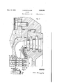
- Fig. 1 is a central vertical section through the whole turbine
- Fig. 2 represents the upper part of Fig. '1 in an enlarged scale showing the passage of the steam from the radially impinged blading to the axially impinged blading; v
- Fig. 3 gives a small part of Fig. 2 with a modified construction of the packing between the 'LWO bladings;
- Fig. 4 shows an end view on the flange supporting the axially impinged stationary blades in the direction of the steam flow.
- the numeral l indicates the shaft revolving inthe bearing 2 which is enclosed in the housing 3.
- the shaft I supports the disc i carrying the rotating blades 5, ii, and i and to the disc 4 is fastened another disc 8 carrying the rotai ing blades 9 which are supported at their other end by means of rings iii.
- the rotating blades 5, '6, and 1 cooperate with the stationary blades vided ring [5, the stationary blades 53 by an axially undivided flange l6 which has no axial split line and thus keeps its circular shape without warp-ing.
- the ring l5 and the flange l6 are clamped to the turbine housing I! by means oi the cover l8 through bolts I! (see Fig.
- All the blades shown are of the reaction type there being a difference in pressure before and behind each row of blades. A certain loss occurs along the tips of the blades on account of leakage. Fine points 26, 21, 28 and 29 are for example provided in Fig. 2 to allow for a minimum clearance thus reducing the leakage losses. The clearance at 28 may be made exceedingly small without any danger of injuring the parts. No stripping during changes in the state of heat of the parts will occur as the flange l6 has no ax al split line which would cause a tendency for warp-- ing.
- the shroud of the blades i3 is 30 enlarged to a stationary part 30 of a labyrinth packing the rotating part 3! being supported by the disc 8. A plurality of fine points.
- the additional labyrinth packing 35/3! does not make the assembling or disassembling of the turbine more difficult- By removing the flange It the parts 20 and I3 together with part 3i! are removed in an axial direction.
- a radial flow turbine in combination, a shaft, a housing, stationary blades adapted to be axially impinged and arranged in one circular row, an annular flange having no axial split line and adapted to support the first row only of said stationary blades, moving blades adapted to be axially impinged and to cooperate with said stationary blades, and a radial flow blading arranged ahead of said stationary blades, on a smaller diameter than said stationary blades, whereby said annular flange is assembled and disassembled in an axial direction.
- a shaft a housing, stationary blades adapted to be axially impinged by a driving medium and arranged in one circular row, an annular flange having no axial split line and adapted to support the first row only of said stationary blades and to be supported by said housing, a rotating disc-supported by said shaft, moving blades adapted to be axially impinged, to be arranged on said rotating disc and to cooperate with said stationary blades, moving blades adapted to be radially impinged, to be arranged in front of said stationary blades, and to be supported by said rotating disc, a stationary disc of smaller diameter than said rotating disc supported by said housing and stationary blades adapted to be radially impinged, to cooperate with said radially impinged moving blades, and to be supported by said stationary disc.
- a shaft a housing, stationary blades adapted to be axially impinged by a driving medium and arranged in one circular row, an annular flange having no axial split line and adapted to support the first row only of said stationary blades and to be supported by said housing, a rotating disc supported by said shaft, moving blades adapted to be axially impinged, to be arranged on said rotating disc and to cooperate with said stationary blades, a second rotating disc of smaller diameter than the first rotating disc supported by said first named rotating disc, moving blades adapted to be radially impinged, to be arranged front of said stationary blades, and to be supported by said second rotating disc, a stationary disc of smaller diameter than the first rotating disc fixed to said annular flange and stationary blades adapted to be radially impinged, to cooperate with said radially impinged moving blades, and to be supported by said stationary disc.
- a shaft a housing, stationary blades adapted to be axially impinged by a driving medium and arranged in one circular row, an annular fiange having no axial split line and adapted to support the first row only of said stationary blades and to be supported by said housing, a rotating disc supported by said shaft, moving blades adapted to be axially impinged, to be arranged on said rotating disc and to cooperate with said stationary blades, a second rotating disc of smaller diameter than'the first rotating disc supported by said first named rotating disc, moving blades adapted to be radially impinged, to
- a shaft a housing, stationary blades adapted to be axially impinged by a driving medium and arranged in one circular row, an annular flange adapted to support said stationary blades and to be supported by said housing, a shroud at the inner tips of said stationary blades, a stationary, radially disposed labyrinth packing fixed to said shroud and adapted to be axially engaged with a rotating labyrinth packing, a rotating disc supported by said shaft, a rotating, radially disposed labyrinth packing fixed to said rotating disc and adapted to be axially engaged with said stationary labyrinth packing, moving blades adapted to be axially impinged, to be arranged on said moving disc and to cooperate with said stationary blades, moving blades adapted to be radially impinged, to be arranged in front of said stationary blades, and to be supported bysaid rotating disc, a stationary disc supported by said housing and stationary blades
- a shaft a housing, stationary blades adapted to beaxially impinged by a driving medium and arranged in one circular row, an annular flange adapted to support said stationary blades and to be supported by said housing,- a shroud atthe inner tips of said stationary blades, a stationary, radially disposed labyrinth packing fixed to said shroud and adapted to be axially engaged with a rotating labyrinth packing, a rotating disc supported by said shaft, moving blades adapted to be axially impinged, to be arranged on said moving disc and to cooperate with said stationary blades, a second rotating disc fixed to said first named rotating disc by means flexible in radial direction, a rotating radially disposed labyrinth packing supported by said second rotating disc and adapted to be axially engaged with said stationary labyrinth packing, moving blades adapted to be radially impinged, to be arranged in front of said stationary blades, and to
- a shaft a housing
- stationary blades adapted to be axially impinged by a driving medium and arranged in one circular row
- an annular flange adapted to support said stationary blades and to be supported by said housing
- a shroud'at the inner tips of said stationary blades a stationary, radially disposed labyrinth packing fixed to said shroud and adapted to be axially engaged with a rotating labyrinth packing
- a rotating disc supported by said shaft
- moving blades adapted to be axially impinged, to be arranged on said moving disc and to cooperate with said stationary blades, the reaction allotted to said moving blades being diminished, while the reaction.
- a shaft a housing, stationary blades adapted to be axially impinged by a driving medium and arranged in one circular row, an annular flange adapted to support said stationary blades and to be supported by said housing, a shroud at the inner tips of said stationary blades, a stationary, radially disposed labyrinth packing fixed to said shroud and adapted to be axially engaged with a rotating labyrinth packing, a rotating disc supported by said shaft, a rotating, radially disposed labyrinth packing integral with said rotating disc and adapted to be axially engaged with said stationary labyrinth packing, moving blades adapted to be axially impinged, to be arranged on said moving disc and to cooperate with said stationary blades, moving blades adapted to be radially impinged, to be arranged in front of said stationary blades, and to be supported by said rotating disc, a stationary disc supported by said housing and stationary blades adapted
- moving blades on said moving disc and to cooperate with said stationary blades, the reaction allotted to said moving blades being diminished, while the reaction of the stationary blades is correspondingly increased, moving blades adapted to be radially impinged, to be arranged in front of said stationary blades, and to be supported by said rotating disc, a stationary disc supported by said housing and stationary blades adapted to be radially impinged, to cooperate with said radially impinged moving blades, and to be supported by said stationary disc.
- a shaft a housing, stationary blades adapted to be axially impinged by a driving medium and arranged in one circular row, an annular flange adapted to support said stationary blades and to be supported by said housing, a shroud at the inner tips of said stationary blades, a stationary, radially disposed labyrinth packing fixed to said shroud and adapted to be axially engaged with a rotating labyrinth packing, a rotating disc supported by said shaft, moving blades adapted to be axially impinged, to be arranged on said moving disc and to cooperate with said stationary blades, a second rotating disc fixed to said first named rotating disc by means flexible in radial direction, a rotating radially disposed labyrinth packing integral with said second rotating disc and adapted to be axially engaged with said stationary labyrinth packing, moving blades adapted to be radially impinged, to be arranged in front of said stationary blades, and to
- a shaft a housing, stationary blades adapted to be axially impinged by a driving medium and arranged in one circular row, an annular flange adapted to support said stationary blades and to be supported by said housing, a shroud at the inner tips of said stationary blades, a stationary, radially disposed labyrinth packing fixed 'tosaid shroud and adapted to be axially engaged with a rotating labyrinth packing, arotating disc supported by said shaft, movingblades adapted to be axially impinged, to be arranged on said moving disc and to cooperate with said stationary blades, the reaction allotted to said moving blades being diminished, while the reaction of the stationary blades is correspondingly increased, a second rotating disc fixed to said first named rotating disc by means flexible in radial direction, a rotating, radially disposed labyrinth packing integral with said second rotating disc and adapted to be axially engaged with said stationary labyrin
Description
Nov. 12, 1935. u. MEININGHAUS TURBINE Nov. 12, 1935. MElNlNGHAUs 2,020,793
TURBINE Filed March 16, 1953 2 Sheets-Sheet 2 Fig.2
INVENTOR Patented Nov. 12, 1935 v UNlTED STATES PATENT OFFICE Application March 16, 1933, Serial No. 661,120 In Germany March 30, 1932 13 Claims.
My invention relates to an improved packing for the blade tips of the first row of axially impinged blading which is arranged behind radially impinged blading as in radial flow turbines where the driving medium at first passes through radially impinged blading and afterwards through axially impinged blading.
The number of radially traversed turbine bladings which can be disposed around one another in the radial direction is known to be limited. The bending stresses exerted on the blades and the tangential forces occurring in the headand root-rings carrying the blades increase with increasing diameter in correspondence with the quickly increasing centrifugal forces to the extent of overstressing the material. It has therefore been the practice to add an axially traversed blading immediately behind the radially traversed blading. conditions of flow at the entrance into the axially impinged blading with small structural length the root diameter of the axially traversed moving blades has to be considerably greater than the exit diameter of the last radially traversed moving blades. Hereby the passage from the radial to the axial direction of fiow involves 2. corresponding discontinuity in mean diameter of admission.
Such an arrangement may be used advantageously with turbines having stationary guide blades even with small volumes of working medium passing through the blades per unit of time as turbines with stationary guide blades must have a higher number of stages than counterrunning turbines to work up the same pressure drop. Turbinesfor small volumes passing through their blades have the inherent property that the clearance iosses occurring at the tips of the reaction blading-only this is suitable, for radially traversed turbines-exert a predominating influence on the efficiency. As the clearance losses are at least proportional to the clearance crosssection and the clearance cross section is at least proportional to the clearance diameter the clearance losses increase strongly on passing from the radial to axial direction of flow on account of said discontinuity of diameter if the expansion of the steam does not outweigh the increase in clearance cross section. This however is not yet the case in the first axially traversed stage though it may be in the following stages. This special phenomenon is particularly disadvantageous in that the axially traversed blading is in known constructions provided with an axial joint for assembling and disassembling. As it is known,
If such an arrangement is to give good axially divided bodies always incline when submitted to alternating heating to deviate at least temporarily from the ring shape. Even such temporary deviations are sufficient to wear away fine packing points and serve to increase substantially the packing clearance and consequently the clearance losses.
The present invention has as its objects to provide an improved packing for the first axially impinged blade row and thus'to obtain an increased efiiciency for the axially impinged blading.
According to my invention I recognize that the specific construction of a radially traversed turbine with stationary blading offers the possil5 bility of constructing the first axially arranged series of guide blades as an undivided ring and that furthermore the above-described disadvantages can herewith be removed to a large extent. According to a feature of the invention therefore, I construct the first axially traversed circle of guide blades as a closed ring without axial joints whereby the insertion and removal is effected in an axial direction. This insertion or removal is particularly facilitated in that the guide blade circle in question is connected with the radially traversed guide blade circles arranged immediately in front of it to form a unitary axially insert-able and removable system in such a way that this has to be supported against the remaining stationary parts by a single flange only.
My invention results further in an additional improvement of packing the blade tips of the first stationary, axially impinged blade row arranged behind the radially impinged blades. I
provide to this end in the space between the root diameter of the axially traversed blading and the last exit diameter of the radially traversed blading a packing consisting of a plurality of radially disposed labyrinth parts which can be slid axially into one another this arrange ment having the object to further decrease the leakage losses. S0 complete a packing is hereby obtained that it is possible to diminish in addition the leakage losses of the appurtenant moving blade series whose working conditions are also not very favorable by diminution of the reaction allotted to it, i. e. the pressure drop to be worked up in it. This results in decreasing the difference in pressure prevailing behind and in front of the moving blade series and consequently the velocity with which the leakage steam is forced through the clearance. Naturally the reaction of the guide blade series, 1. e. the pressure drop operating in it, must be correspondingly increased. In consequence of the now extremely eifective packing of this row, however, the clearance loss does not increase to a disadvantageous extent even on an increased difference in the pressure prevailing in front of and behind the guide blades. The stationary part of the radially arranged packing advantageously constitutes in this case an extension of the cover band of the guide blade series whereby both together conveniently possess an L-shaped form. I attach the rotatory part of the packing to a disc supporting the radially traversed blading whereby the support may be made flexible as to allow for different expansion during the period of heating up or cooling off. There is no danger in doing so because the thin walled supports of the radially traversed blade groups themselves at once follow all thermal variations and consequently the flexible connection is only slightly stressed whilst in relation to the thermally inert disc which carries the axially traversed blading considerable differences in diameter would occur which would stress the flexible connection highly if it were fastened to said disc.
But with a rigid connection of the rotating parts of the packing to a thin walled disc, i. e. a disc supporting the radially impinged blades constructed in accordance with application. Serial Number 600,500 of March 22, 1932. I obtain the further improvement that the increase in the diameters of these parts due to the centrifugal force which makes it difficultas above said-to keep small clearances in the packing will be kept Within comparatively small limits. As the increase in the diameters due to centrifugal force is proportional to the square of the diameter in question this increase would be very considerable With the diameters of the packing unless the radial expansion were limited by means of the rigid connection with a disc of smaller diameter. But I obtain greatest improvement if the rotating packing parts are made integral with adisc supporting the radially impinged blades which is itself capable of following immediately any change in the state of heat of the driving medium.
The drawings show schematically and by way of example a construction according to the inventive idea applied to a radial flow condensing steam turbine with an overhung shaft. In said drawings,
Fig. 1 is a central vertical section through the whole turbine;
Fig. 2 represents the upper part of Fig. '1 in an enlarged scale showing the passage of the steam from the radially impinged blading to the axially impinged blading; v
Fig. 3 gives a small part of Fig. 2 with a modified construction of the packing between the 'LWO bladings; and
Fig. 4 shows an end view on the flange supporting the axially impinged stationary blades in the direction of the steam flow.
In Fig. 1, the numeral l indicates the shaft revolving inthe bearing 2 which is enclosed in the housing 3. The shaft I supports the disc i carrying the rotating blades 5, ii, and i and to the disc 4 is fastened another disc 8 carrying the rotai ing blades 9 which are supported at their other end by means of rings iii. The rotating blades 5, '6, and 1 cooperate with the stationary blades vided ring [5, the stationary blades 53 by an axially undivided flange l6 which has no axial split line and thus keeps its circular shape without warp-ing. The ring l5 and the flange l6 are clamped to the turbine housing I! by means oi the cover l8 through bolts I!) (see Fig. 2). the flange 6 a stationary disc 20 is fastened which supports the stationary blades M the other ends of which are held by the rings 2|. The blades 9 and M are fastened to the discs 8 and and to the rings Ii] and 2| by means of extensions 22 10 and 23 which are inserted in corresponding slots,
as shown in Fig. 2.
Steam enters the turbine through pipe 24, flows in a radial direction through the blades 9 and changes to the axial direction and flows through the blades 13, I, I2, 6, H and 5 and finally leaves the turbine at 25.
All the blades shown are of the reaction type there being a difference in pressure before and behind each row of blades. A certain loss occurs along the tips of the blades on account of leakage. Fine points 26, 21, 28 and 29 are for example provided in Fig. 2 to allow for a minimum clearance thus reducing the leakage losses. The clearance at 28 may be made exceedingly small without any danger of injuring the parts. No stripping during changes in the state of heat of the parts will occur as the flange l6 has no ax al split line which would cause a tendency for warp-- ing. In addition, the shroud of the blades i3 is 30 enlarged to a stationary part 30 of a labyrinth packing the rotating part 3! being supported by the disc 8. A plurality of fine points. 32 makes for a very tight joint and decreases the leakage loss in the blade row I3 to such an extent that 35 a greater heat drop may be allotted to the blade row 13 decreasing the corresponding heat drop in the blade row I and thus diminishing the difference in pressure before and behind such row and therewith the leakage losses.
In Fig. 3 a flexible connection between the rotary part 3| of the labyrinth with the disc 8 is shown by means of a thin extension 33 which is caulked into the disc 8 with a wire 34. Preferably the rotary part 3! is made integral with the disc 8 as shown in Fig. 2 because in this way the part 3| will be subjected to less deformation due to centrifugal force.
The additional labyrinth packing 35/3! does not make the assembling or disassembling of the turbine more difficult- By removing the flange It the parts 20 and I3 together with part 3i! are removed in an axial direction.
Fig. 4 gives a view on the flange l6 and the disc 20 fastened to it in the direction of the flow of the steam as entering through the pipe 24. The figure has been added to show that the flange I5 is constructed as one single part having no axial split line which construction is essential for obtaining the above described advantages.
I claim:
1. In a radial flow turbine in combination, a shaft, a housing, stationary blades adapted to be axially impinged and arranged in one circular row, an annular flange having no axial split line and adapted to support the first row only of said stationary blades, moving blades adapted to be axially impinged and to cooperate with said stationary blades, and a radial flow blading arranged ahead of said. stationary blades on a smaller diameter than said stationary blades.
2. In a. radial flow turbine in combination, a shaft, a housing, stationary blades adapted to be axially impinged and arranged in one circular row, an annular flange having no axial split line and adapted to support the first row only of said stationary blades, moving blades adapted to be axially impinged and to cooperate with said stationary blades, and a radial flow blading arranged ahead of said stationary blades, on a smaller diameter than said stationary blades, whereby said annular flange is assembled and disassembled in an axial direction.
3. In a radial flow turbine in combination, a shaft, a housing, stationary blades adapted to be axially impinged by a driving medium and arranged in one circular row, an annular flange having no axial split line and adapted to support the first row only of said stationary blades and to be supported by said housing, a rotating disc-supported by said shaft, moving blades adapted to be axially impinged, to be arranged on said rotating disc and to cooperate with said stationary blades, moving blades adapted to be radially impinged, to be arranged in front of said stationary blades, and to be supported by said rotating disc, a stationary disc of smaller diameter than said rotating disc supported by said housing and stationary blades adapted to be radially impinged, to cooperate with said radially impinged moving blades, and to be supported by said stationary disc. I
4. In a radial flow turbine in combination, a shaft, a housing, stationary blades adapted to be axially impinged by a driving medium and arranged in one circular row, an annular flange having no axial split line and adapted to support the first row only of said stationary blades and to be supported by said housing, a rotating disc supported by said shaft, moving blades adapted to be axially impinged, to be arranged on said rotating disc and to cooperate with said stationary blades, a second rotating disc of smaller diameter than the first rotating disc supported by said first named rotating disc, moving blades adapted to be radially impinged, to be arranged front of said stationary blades, and to be supported by said second rotating disc, a stationary disc of smaller diameter than the first rotating disc fixed to said annular flange and stationary blades adapted to be radially impinged, to cooperate with said radially impinged moving blades, and to be supported by said stationary disc.
5. In a radial flow turbine in combination, a shaft, a housing, stationary blades adapted to be axially impinged by a driving medium and arranged in one circular row, an annular fiange having no axial split line and adapted to support the first row only of said stationary blades and to be supported by said housing, a rotating disc supported by said shaft, moving blades adapted to be axially impinged, to be arranged on said rotating disc and to cooperate with said stationary blades, a second rotating disc of smaller diameter than'the first rotating disc supported by said first named rotating disc, moving blades adapted to be radially impinged, to
be arranged in front of said stationary blades,
and to be supported by said second rotating disc, a stationary disc of smaller diameter than the first rotating disc fixed to said annular flange and stationary blades adapted to be radially impinged, to cooperate with said radially impinged moving blades, and to be supported by said stationary disc, whereby said annular flange is assembled and disassembled in an axial direction together with said stationary disc.
6. In a radial flow turbine in combination, a shaft, a housing, stationary blades adapted to be axially impinged by a driving medium and arranged in one circular row, an annular flange adapted to support said stationary blades and to be supported by said housing, a shroud at the inner tips of said stationary blades, a stationary, radially disposed labyrinth packing fixed to said shroud and adapted to be axially engaged with a rotating labyrinth packing, a rotating disc supported by said shaft, a rotating, radially disposed labyrinth packing fixed to said rotating disc and adapted to be axially engaged with said stationary labyrinth packing, moving blades adapted to be axially impinged, to be arranged on said moving disc and to cooperate with said stationary blades, moving blades adapted to be radially impinged, to be arranged in front of said stationary blades, and to be supported bysaid rotating disc, a stationary disc supported by said housing and stationary blades adapted to be radially impinged, to cooperate with said radially impinged moving blades, and to be supported by said stationary disc.
7. In a radial fiow turbine in combination, a shaft, a housing, stationary blades adapted to be axially impinged by a driving medium and arranged in one circular row, an annular fiange adapted to support said stationary bladesand to be supported by said housing, a shroud at the inner tips of said stationary blades, a stationary,
radially disposed labyrinth packing fixed to said shroud and adapted to be axially engaged with a rotating labyrinth packing, a rotating disc sup ported by said shaft, a rotating, radially disposed labyrinth packing fixed to said rotating disc and adapted to be axially engaged with said station,- ary labyrinth packing, moving blades adapted to be axially impinged, to bearranged on said moving disc and to cooperate with said stationary blades, the reaction allotted to said moving blades being diminished, while the reaction of the stationary blades is correspondingly increased, moving blades adapted to be radially impinged, to be arranged in front of said stationary blades, and to be supported by said rotating .disc, a stationary disc supported by said housing and stationary blades adapted to be radially impinged, to cooperate with said radially impinged moving blades, and to be supported by said stationary disc.
8. In a radial flow turbinein combination, a shaft, a housing, stationary blades adapted to beaxially impinged by a driving medium and arranged in one circular row, an annular flange adapted to support said stationary blades and to be supported by said housing,- a shroud atthe inner tips of said stationary blades, a stationary, radially disposed labyrinth packing fixed to said shroud and adapted to be axially engaged with a rotating labyrinth packing, a rotating disc supported by said shaft, moving blades adapted to be axially impinged, to be arranged on said moving disc and to cooperate with said stationary blades, a second rotating disc fixed to said first named rotating disc by means flexible in radial direction, a rotating radially disposed labyrinth packing supported by said second rotating disc and adapted to be axially engaged with said stationary labyrinth packing, moving blades adapted to be radially impinged, to be arranged in front of said stationary blades, and to be supported by said second rotating disc, a stationary disc fixed to said annular flange and stationary blades adapted to be radially impinged, to cooperate with said radially impinged moving blades, and to be supported by said stationary disc.
9. In a radial flow turbine in combination, a shaft, a housing, stationary blades adapted to be axially impinged by a driving medium and arranged in one circular row, an annular flange adapted to support said stationary blades and to be supported by said housing, a shroud'at the inner tips of said stationary blades, a stationary, radially disposed labyrinth packing fixed to said shroud and adapted to be axially engaged with a rotating labyrinth packing, a rotating disc supported by said shaft, moving blades adapted to be axially impinged, to be arranged on said moving disc and to cooperate with said stationary blades, the reaction allotted to said moving blades being diminished, while the reaction. of the stationary blades is, correspondingly increased, a second rotating disc fixed to said first named rotating disc by means flexible in radial direction, a rotating radially disposed labyrinth packing supported by said second rotating disc and adapt-- ed to be axiallyengaged with said stationary labyrinth packing,,moving blades adapted to be radially impinged, to be arranged in front of said stationary blades, and to be supported by said second rotating disc, a stationary disc fixed to said annular flange and stationary blades adapted to be radially impinged, to cooperate with said radially impinged moving blades, and to be supported by said stationary disc.
10. In a radial flow turbine in combination, a shaft, a housing, stationary blades adapted to be axially impinged by a driving medium and arranged in one circular row, an annular flange adapted to support said stationary blades and to be supported by said housing, a shroud at the inner tips of said stationary blades, a stationary, radially disposed labyrinth packing fixed to said shroud and adapted to be axially engaged with a rotating labyrinth packing, a rotating disc supported by said shaft, a rotating, radially disposed labyrinth packing integral with said rotating disc and adapted to be axially engaged with said stationary labyrinth packing, moving blades adapted to be axially impinged, to be arranged on said moving disc and to cooperate with said stationary blades, moving blades adapted to be radially impinged, to be arranged in front of said stationary blades, and to be supported by said rotating disc, a stationary disc supported by said housing and stationary blades adapted to be radially impinged, to cooperate with said radially impinged moving blades, and to be supported by said stationary disc.
11. In a radial flow turbine in combination, a
shaft, a housing, stationary blades adapted to be,
moving blades on said moving disc and to cooperate with said stationary blades, the reaction allotted to said moving blades being diminished, while the reaction of the stationary blades is correspondingly increased, moving blades adapted to be radially impinged, to be arranged in front of said stationary blades, and to be supported by said rotating disc, a stationary disc supported by said housing and stationary blades adapted to be radially impinged, to cooperate with said radially impinged moving blades, and to be supported by said stationary disc.
12. In a radial flow turbine in combination, a shaft, a housing, stationary blades adapted to be axially impinged by a driving medium and arranged in one circular row, an annular flange adapted to support said stationary blades and to be supported by said housing, a shroud at the inner tips of said stationary blades, a stationary, radially disposed labyrinth packing fixed to said shroud and adapted to be axially engaged with a rotating labyrinth packing, a rotating disc supported by said shaft, moving blades adapted to be axially impinged, to be arranged on said moving disc and to cooperate with said stationary blades, a second rotating disc fixed to said first named rotating disc by means flexible in radial direction, a rotating radially disposed labyrinth packing integral with said second rotating disc and adapted to be axially engaged with said stationary labyrinth packing, moving blades adapted to be radially impinged, to be arranged in front of said stationary blades, and to be supported by said second rotating disc, a stationary disc fixed to said annular flange and stationary blades adapted to be radially impinged, to cooperate with said radially impinged moving blades, and to be supported by said stationary disc. 7
13. In a radial flow turbine in combination, a shaft, a housing, stationary blades adapted to be axially impinged by a driving medium and arranged in one circular row, an annular flange adapted to support said stationary blades and to be supported by said housing, a shroud at the inner tips of said stationary blades, a stationary, radially disposed labyrinth packing fixed 'tosaid shroud and adapted to be axially engaged with a rotating labyrinth packing, arotating disc supported by said shaft, movingblades adapted to be axially impinged, to be arranged on said moving disc and to cooperate with said stationary blades, the reaction allotted to said moving blades being diminished, while the reaction of the stationary blades is correspondingly increased, a second rotating disc fixed to said first named rotating disc by means flexible in radial direction, a rotating, radially disposed labyrinth packing integral with said second rotating disc and adapted to be axially engaged with said stationary labyrinth packing, moving blades adapted to be axially impinged, to be arranged in front of said stationary blades, and to be supported by said second rotating disc, a stationary disc fixed to said annular flange and stationary blades adapted to be radially impinged, to cooperate with said radially impinged moving blades, and to be supported by said stationary disc.
ULRICH MEININGHAUS.
Applications Claiming Priority (1)
| Application Number | Priority Date | Filing Date | Title |
|---|---|---|---|
| DE2020793X | 1932-03-30 |
Publications (1)
| Publication Number | Publication Date |
|---|---|
| US2020793A true US2020793A (en) | 1935-11-12 |
Family
ID=7971369
Family Applications (1)
| Application Number | Title | Priority Date | Filing Date |
|---|---|---|---|
| US661120A Expired - Lifetime US2020793A (en) | 1932-03-30 | 1933-03-16 | Turbine |
Country Status (1)
| Country | Link |
|---|---|
| US (1) | US2020793A (en) |
Cited By (6)
| Publication number | Priority date | Publication date | Assignee | Title |
|---|---|---|---|---|
| US2452581A (en) * | 1944-06-07 | 1948-11-02 | Standard Telephones Cables Ltd | Turbogenerator |
| US2933287A (en) * | 1956-05-28 | 1960-04-19 | Alfred M Caddell | Multiple stage turbine unit |
| US4792278A (en) * | 1987-08-14 | 1988-12-20 | Allied-Signal, Inc. | Turbocooler with multistage turbine wheel |
| US5803733A (en) * | 1997-05-06 | 1998-09-08 | Linvatec Corporation | Pneumatic surgical handpiece and method |
| US20170107819A1 (en) * | 2014-03-21 | 2017-04-20 | Exergy S.P.A. | Radial turbomachine |
| CN107429567A (en) * | 2015-04-03 | 2017-12-01 | 图博登股份公司 | It is preferred for the multi-stage turbine of organic Rankine bottoming cycle (ORC) equipment |
-
1933
- 1933-03-16 US US661120A patent/US2020793A/en not_active Expired - Lifetime
Cited By (10)
| Publication number | Priority date | Publication date | Assignee | Title |
|---|---|---|---|---|
| US2452581A (en) * | 1944-06-07 | 1948-11-02 | Standard Telephones Cables Ltd | Turbogenerator |
| US2933287A (en) * | 1956-05-28 | 1960-04-19 | Alfred M Caddell | Multiple stage turbine unit |
| US4792278A (en) * | 1987-08-14 | 1988-12-20 | Allied-Signal, Inc. | Turbocooler with multistage turbine wheel |
| US5803733A (en) * | 1997-05-06 | 1998-09-08 | Linvatec Corporation | Pneumatic surgical handpiece and method |
| US20170107819A1 (en) * | 2014-03-21 | 2017-04-20 | Exergy S.P.A. | Radial turbomachine |
| US10876406B2 (en) * | 2014-03-21 | 2020-12-29 | Exergy S.P.A. | Radial turbomachine |
| US11339661B2 (en) | 2014-03-21 | 2022-05-24 | Exergy International S.R.L. | Radial turbomachine |
| CN107429567A (en) * | 2015-04-03 | 2017-12-01 | 图博登股份公司 | It is preferred for the multi-stage turbine of organic Rankine bottoming cycle (ORC) equipment |
| US20180283177A1 (en) * | 2015-04-03 | 2018-10-04 | Turboden Spa | Multistage turbine preferably for organic rankine cycle orc plants |
| US10526892B2 (en) * | 2015-04-03 | 2020-01-07 | Turboden Spa | Multistage turbine preferably for organic rankine cycle ORC plants |
Similar Documents
| Publication | Publication Date | Title |
|---|---|---|
| US2910268A (en) | Axial flow fluid machines | |
| US2241782A (en) | Gas turbine | |
| US2213940A (en) | Rotor for gas turbines and rotary compressors | |
| US2080425A (en) | Turbine | |
| US3043561A (en) | Turbine rotor ventilation system | |
| US4948333A (en) | Axial-flow turbine with a radial/axial first stage | |
| US2282894A (en) | Elastic fluid turbine | |
| GB1395957A (en) | Fluid flow machines and rotors therefor | |
| US2020793A (en) | Turbine | |
| GB1301002A (en) | Improvements relating to fluid-flow machines | |
| US2724545A (en) | Discharge casings for axial flow engines | |
| US2435042A (en) | Plural fluid turbine combining impulse and reaction blading | |
| US2399009A (en) | Elastic fluid turbine | |
| US2058479A (en) | Turbine for hot driving media | |
| US2724546A (en) | Gas turbine apparatus | |
| US2405164A (en) | Turbine stator | |
| US3582230A (en) | Turbomachine with cooled rotor | |
| US2514039A (en) | Fluid pressure turbine | |
| US2047501A (en) | Steam or gas turbine | |
| US2462600A (en) | Turbine | |
| US2332322A (en) | Elastic fluid turbine arrangement | |
| GB789204A (en) | Improvements in or relating to axial flow compressors or turbines | |
| US1910845A (en) | Radial flow turbine | |
| US2467168A (en) | High-temperature turbomachine | |
| US1927944A (en) | Blade ring for radial flow elastic fluid turbines |