US2020344A - Method and machine for operating on soles - Google Patents
Method and machine for operating on soles Download PDFInfo
- Publication number
- US2020344A US2020344A US661666A US66166633A US2020344A US 2020344 A US2020344 A US 2020344A US 661666 A US661666 A US 661666A US 66166633 A US66166633 A US 66166633A US 2020344 A US2020344 A US 2020344A
- Authority
- US
- United States
- Prior art keywords
- sole
- shank
- forepart
- pattern
- devices
- Prior art date
- Legal status (The legal status is an assumption and is not a legal conclusion. Google has not performed a legal analysis and makes no representation as to the accuracy of the status listed.)
- Expired - Lifetime
Links
- 238000000034 method Methods 0.000 title description 19
- 238000003825 pressing Methods 0.000 description 8
- 238000011084 recovery Methods 0.000 description 7
- 238000007493 shaping process Methods 0.000 description 6
- 239000011435 rock Substances 0.000 description 4
- 238000010276 construction Methods 0.000 description 3
- FPIPGXGPPPQFEQ-OVSJKPMPSA-N all-trans-retinol Chemical compound OC\C=C(/C)\C=C\C=C(/C)\C=C\C1=C(C)CCCC1(C)C FPIPGXGPPPQFEQ-OVSJKPMPSA-N 0.000 description 2
- 238000013459 approach Methods 0.000 description 2
- 238000006073 displacement reaction Methods 0.000 description 2
- 230000005484 gravity Effects 0.000 description 2
- 239000011717 all-trans-retinol Substances 0.000 description 1
- 235000019169 all-trans-retinol Nutrition 0.000 description 1
- 238000005452 bending Methods 0.000 description 1
- 244000221110 common millet Species 0.000 description 1
- 230000001771 impaired effect Effects 0.000 description 1
- 230000000284 resting effect Effects 0.000 description 1
- KDYFGRWQOYBRFD-UHFFFAOYSA-N succinic acid Chemical compound OC(=O)CCC(O)=O KDYFGRWQOYBRFD-UHFFFAOYSA-N 0.000 description 1
Images


Classifications
-
- A—HUMAN NECESSITIES
- A43—FOOTWEAR
- A43D—MACHINES, TOOLS, EQUIPMENT OR METHODS FOR MANUFACTURING OR REPAIRING FOOTWEAR
- A43D35/00—Presses for shaping pre-existing loose soles, shoe bottoms or soles fixed to shoe bottoms
Definitions
- This invention relates to methods of and ma chines for operating on soles and is illustrated herein with reference to the shaping of shoe soles both longitudinally and transversely as is contemplated also by United States Letters Patent No. 1,939,750, granted December 19, 1933 upon an application filed in my name and United States Letters Patent No. 1,772,038, granted August 5, 1930, upon application of H. A. Davenport and N. F. Hopkins.
- a sole is treated in accordance with the inventions disclosed in the Letters Patent referred to above by having portions of the fore and heel parts relatively positioned to give the shank the angular relation to the fore and heel parts which it is to have in the finished shoe, and then by having the shank portion operated upon by a tool which imparts the desired transverse curvature to the shank.
- an object of the invention is to provide an improved method of and machine for operating on shoe soles by the use of which the above-mentioned tendency is corrected.
- the invention in one aspect contemplates the shaping ofa shoe sole by relatively positioning the fore and heel parts of the sole so as to give the intermediate shank portion such an angular relation with respect to the fore and heel parts as it is to have in the finished shoe, controlling the portion of the sole in the vicinity of the ball line and displacing the marginal portions of the shank relatively to the central portion thereof, thereby to portion of the sole in the vicinity of the ball line 5 V is effected, after the fore and heel parts of the sole have been positioned as described above, by applying pressure to portions of the forepart and shank contiguous to the ball line.
- Invention is also to be recognized in an improved machine constructed and arranged to operate upon a shoe sole in the above defined manner.
- means for relatively positioning the fore and heel parts of the sole so as to give the intermediate shank portion such an angular relation to the fore and heel parts as it is to have in the finished shoe, members mounted for relative movement toward and away from each other shaped and arranged to operate upon the sole shank and a portion of the forepart contiguous to the'ball line, and means for relatively moving said members toward each other thereby to control the portion of the forepart of the sole contiguous to the ball line by applying pressure to the said portion of the forepart and to impart a permanent transverse curvature to the shank and by stretching its margins with respect to the axial portion beyond their limit 'of elastic recovery;
- the relative positioning of the fore and heel parts of the sole is
- one is adapted to support the axial portion of the shank and the portion of the forepart contiguous to the ball line, and the other is mounted for movement toward and away from the first-mentioned member and has a sole engaging surface shaped with reference to that of the first-mentioned member so that all parts of the sole are made to conform strictly to the desired shape. It will be found that a sole, when treated in this manner and by this means, will lack any distortion from the desired'shape of the portion of the forepart contiguous to the ball line even when relatively extreme longitudinal and transverse curvatures are imparted to the shank.
- Machines requiring a sole to be positioned definitely with respect to its operating instrumentalities are sometimes provided with means for locating the sole by engagement with an edge of the sole.
- the effectiveness of the locating means may be impaired by jarring of the located sole as a result of the normal movement of the sole itself into a position in which it is operated upon or of the undesirable but inevitable vibrations caused by the more remote operating parts of the machine.
- another object of the present invention is to provide improved means for locating a sole with respect to means for operating upon it, and with this object in view, one feature of the invention consists in the combination with devices for operating upon soles mounted for relative movement toward and away from each other, of sole locating means, a sole engaging member disposed normally within the field of action of said devices, and means for moving the sole engaging member away from the field of action of said devices so as frictionally to urge the sole against the 10- cating means. It is apparent that by the use of a construction such as is defined above any tendency of the sole to be moved away from the locating means, is overcome throughout the relative movement between the sole engaging member, herein illustrated as a support, and the 10- cating means.
- the above-mentioned movement of the sole engaging member or support is effected in the illustrated machine by means actuated by the relative movement of the sole treating devices toward each other.
- the invention also contemplates the provision of means for moving the sole locating means out of engagement with the sole edge, for example, toward or at the end of the relative movement between the sole engaging member or support and the sole locating means, whereby the danger of either the sole locating means or the sole support being damaged by the sole treating devices is entirely obviated.
- a part of the sole locating means in the construction shown is spaced from but disposed in the path of movement of the sole support whereby the support and locating means are moved away from the sole in succession as the operating devices are moved relatively toward each other.
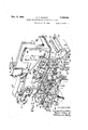
- Fig. 1 is a front elevation of part of a machine the desired angular relation between the shank in which the invention is illustrated as embodied;
- Fig. 2 is a perspective View of the sole treating and positioning instrumentalities shown in Fig. 1;
- Fig. 3 is a view in plan illustrating the sole positioning devices and their operative relation to to the sole treating instrumentalities
- Fig. 4 is a perspective view partly in section and broken away illustrating the sole treating instrumentalities at an early stage in their operation upon a sole;
- Fig. 5 is a perspective view similar to Fig. 4
- Fig. 6 is a sectional view taken along the plane indicated by the lines VI-VI of Fig. 5;
- Fig. '7 is a view in perspective of the work engaging element of the conforming tool illustratingthe shape of its work engaging surface
- Fig. 8 is a side elevation, the sole positioning element having'been removed, and illustrating diagrammatically the operative relation between the pattern and sole conforming tool;
- Fig. 9 is a perspective view of a sole which has been treated by a machine constructed in accordance with the present invention. 7
- the illustrated machine has sole controlling devices comprising heel part and forepart clamp tables In and I2, and also heel part and forepart clamps l4 and I6.
- sole controlling devices comprising heel part and forepart clamp tables In and I2, and also heel part and forepart clamps l4 and I6.
- a rubber sheet I 8 extends across the gap between the clamps l4 and I6 and covers their lower surfaces.
- the clamp tables l0 and I2 are arranged to swing relatively to the clamps I 4 and I6 between a sole receiving position toward the front of the machine, in which a sole to be treated is placed on a heel part element 20 and a pattern 22 carried by the clamp tables I0 and I2 respectively, to a position in which the element 20 and the pattern 22 are alined with, but spaced from, the clamps l4 and It, as described in Letters Patent No.
- the sole engaging surface of the forepart portion 24' of the pattern may, if desired, be convexly shaped, as indicated in Figs. 4 and 5, in order to impart such a curvature to the forepart of a sole as it is to have in the finished shoe. In such a case, a similar curvature is given to the lower surface of the forepart clamp 16.
- the illustrated pattern 22 also comprises a shank portion 28 which is integral with the forepart portion 24 and has substantially the same angular relation thereto as that which is to exist between the shank and forepart portions of the shoes for which soles treatedin the machine are intended.
- the rearward end of the shank. portion '25 is not supported by the heel part clamp table l9, as is the case in my prior machine, but engages an abutment 28 which extends beneath a part of the heel clamp table 29 and is carried by the central web 39 of the upper frame 32 of the machine (Fig. l).
- the sole engaging surfaces of the forepart and shank elements of the illustrated pattern 22 merge at a rather definite edge 36 which imparts to a sole pressed firmly thereagainstan abrupt change in its direction at the ball line commonly called a break which is required in some shoes by thei style. While the break referred to is relatively pronounced in soles which have been operated upon by the pattern illustrated herein, it is to be understood that whether the break is sharp or gradual is immaterial to the invention.
- ransverse curvature of the shank portion 2% of the pattern is preferably made somewhat sharper than that of the sole as embodied in the finished shoe in order that the shank of the sole may be curved in excess of the desired amount and that its edges will therefore tend to hug the adjacent portion of the upper when the sole is attached to the upper.
- the sole clampinginstrumentalities illustrated herein after having been brought together to grip the fore and heel part ends of the sole, are moved relatively to each other heightwise of the tread surface of the sole, thereby to position the fore and heel parts in such a way as to give the shank the same angular relation to thefore and heel parts which it is to have in the finished shoe.
- This treatment of the sole may be eifected, either with or without stretching the shank portion of the sole bodily, depending upon the adjustment of a link 36 which is adjustably clamped at one end to a bracket 33 associated with the heel part clamp id and which is fixed at its other end to a slide 59 mounted in a slideway member 52 associated with the forepart clamp It.
- the clamps I l, 86 can be relatively positioned longitudinally of the sole by adjustment of the slide 39 with respect to the slideway member d2, which may be effected in. the illustrated machine by turning a knob
- the link 36 is illustrated herein as being so positioned as to cause no overall stretching of the sole as its fore and heel parts are relatively moved heightwise into the positions they occupy in Figs. 4 and 5.
- the abovementioned relative heightwise displacement of the forepart and heel part clamps is obtained by dropping the heel part clamping devices .so that the upper surface of the end of the shank element 9.6 of the pattern adjacent to the heel part clamp is substantially continuous with the upper surface of the heel part engaging element 29; and during this movement of the heel part clamping devices the forepart clamping devices are moved bodily to the right as seen in Fig. 1 so as not to cause the shank of the sole to be'stretched over all, there being relative sliding movement at this time between the contacting portions of the abutment 2% and the shank portion 2-5 of the pattern.
- locating devices one of which comprises an abutment 46 adapted to be engaged by the toe end of the sole and thus to limit movement of the sole the operator.
- the abutment it is provided with a shoulder 52; a sole support 5 is arranged to cooperate with the locating member i8; and the locating member is notched to provide a sole supporting surface 55 contiguous to its sole edge engaging surface, as clearly shown in Fig. 2.
- the above-named forepart and heel part locating means are carried on slides 53 and 59 respectively, mounted for movement on slideway members 52, which can be adjusted angularly with respect to the longitudinal axis of the pattern, and held in adjusted position by means of clamp screws 6%.
- soles of different sizes can be positioned both longitudinally and widthwise of the pattern asa result of a single movement of the locating means, this movement being effected in the present machine, as well as in the prior machine, through rock levers 66 which are positioned when the clamp table-s are swung into sole receiving position and the movement of which levers is transmitted to the slides 58 and Gil through square rods 68 which are received within slots in the slides 58 and 65.
- a sole may be both positioned longitudinally and widthwise of the pattern and also supported against the force of gravity at the toe end and at two points along the side nearer the operator by means of the above described instrumentalities.
- the sole will also usually engage the pattern at a point opposite the locating member 48 adjacent to the rear edge Lost motion between the slides of the sole. and 6!! and the slideway members 92 is eliminated by springs l8, Fig. 2, which urge upwardly T-headed bolts A? which hold the slides 58 and in assembled relation with the slideway mem bers 62.
- the abutment 46 is disposed in a recess in the upper surface of the pattern 22 and is mounted for adjustment longitudinally of the pattern 22 on a bracket 74 to which the abutment 46. can be i clamped by means of a screw it; and the bracket -74 is mounted yieldingly to swing downwardly, if
- the bracket i6 is also provided with an index 82 which indicates the adjustment of the abutment 16 with respect to the bracket 14.
- the forepart locating member 48 consists of a rod one end of which is bent upwardly, as indicated in Fig. 2 so as to engage the edge of the sole.-
- the rod is rotatably mounted in a support 84 which, together with the sole support 54, is pivoted by means of a screw 86 on the slide 58.
- the bent or sole engaging end of the locating member 48 is normally urged toward an upstanding position by means of a. coiled spring 88 attached to the support 84 and which will allow the sole engaging portion of the locating member to be swung substantially into the plane of the sole if the clamp I6 is moved against it.
- the normal lateral position of the member 48 with respect to the pattern 22 is determined by an adjustable stop 90 which engages a lug 92 on the support 84.
- the stop 90 is threaded in the slide 58 and thus can be turned adjustably to position the member 48 with respect'to the pattern 22.
- the position of the member 48 with respect to the pattern is indicated at all times by an index 94 carried by the stop 90, as plainly shown in Figs. 2 and 3.
- the support 84 is urged in a clockwise direction (Fig. 3) to hold the lug 92 against the stop 90 by means of a spring 96 connecting the support 84 and the slide 58.
- the sole support 54 is so mounted as to have limited movement with respect to the locating member 48, and to this end is notched at 58 to receive a pin I carried by the support 84.
- the length of the notch is great enough with respect to the diameter of the pin I80, to allow the sole engaging portion of the support 54 to be moved out of engagement with the bottom surface of the sole without imparting any movement to the sole locating means 48.
- member 54 is yieldingly held so as normally to extend under the bottom of a sole, the edge of which is held against the locating member 48, by means of a spring I82 coiled about the screw 86 and the ends of which abut against pins carried by the sole supporting member 54 and the support 84 for the sole locating member 48.
- the invention provides additional mechanism which successively removes the sole support 54 from engagement with the sole, thereby frictionally urging the sole edge against the sole locating member 48, and then removes the sole locating member 48 as well as the support 54 from the field of action of the sole clamping devices.
- This operation is effected by the relative movement of the sole clamping devices toward each other by means of a bell crank I04 (Fig. 2) mounted on a standard I06 attached to the clamp table I2.
- One arm I08 of the bell crank I04 is engaged by a finger I I 0 pivotally attached to the lower portion of the slide 40 and is thereby rotated downwardly (Fig. 2) when the clamp I6 is moved relatively toward the pattern 22.
- the heel part locating member 50 is rotatably supported on a pin I I6 carried by a slide I I8 arranged for movement laterally of the pattern and. sole in a slideway in the slide 60. Adjustment of the member 50 toward and from the longitudinal axis of the pattern can be efiected by turning a knob I20, mounted in the slide 60, and having The sole supporting formed integral therewith a pinion meshing with a rack I22 on the slide II8.
- An index I24 is arranged, as illustrated in Fig. 3, to indicate the relative positions of the slide I I 8 and the slide 60.
- the description given above relating to the construction and use of the sole positioning instrumentalities may be summarized as follows: Assuming that the slideway members 62 have been positioned angularly with respect to the clamp tables I0 and I2 in the desired manner and in accordance with the relation of the variations in length and width of soles of different sizes but of the same style, the slides 58 and 60 are definitely positioned with respect to the slideways when the pattern is moved by the swinging of the clamp tables I0 and I2 to its sole receiving position, such, for example, as that in which it is illustrated in Fig. 6 in Letters Patent No. 1,939,750 referred to above. A sole is then positioned with respect to the pattern 22 with the help of the gaging instrumentalities 46, 48, 50 and 54 referred to above.
- the sole is placed over the pattern in abutting relation to the positioning devices by means of a movement directed in part toward the left (Fig. 3) to cause the toe end of the sole to engage the abutment 46, and partly toward the front of the machine to cause the edge of the sole adjacent to the members 48 and 50 to be placed against them.
- the sole is supported against the force of gravity by resting upon the shoulder 52, the supporting member 54, the surface 56 of the member 58, and also usually by the pattern 22 adjacent to the sole edge directly opposite to the portion of the sole edge engaged by the member 48.
- the clamp tables I0 and I2 are then swung by their operating mechanism into a position of alinement with but spaced from the clamps I4 and IS, and, as soon as this movement has been completed, the clamps are moved toward the clamp tables in order to cause the fore and heel parts of the sole to be gripped.
- the movement of the clamp I6 toward the forepart portion 24 of the pattern 22 is utilized successively to move the sole support 54 out of engagement with the lower surface of the sole and to move the sole locating member 48 out of engagement with the sole edge.
- This operation of the sole engaging members is initiated by the finger IIO associated with the slide 40 when it engages in its downward movement the arm I08 of the bell crank I84.
- the forming of the sole in the vicinity of the break and throughout the shank portion is effectcd in the operation of the illustrated machine by controlling the portion of the forepart contiguous to the ball line and displacing the marginal portions of the shank relatively to the central or axial portion thereof.
- the sole is treated in both of the ways referred to above simultaneously by causing a conforming tool, herein illustrated as having a'rubber pad I39 (Fig. 7), to exert a pressure against the sole in a direction included by the angle between the longitudinal axis A-A,of the forepart and a chord BB subtending the shank portion of the sole as illustrated in Fig. 8.
- the pad 530 as shown in Figs.
- the pad I39 has a forepart surface' 532 which is curved or planein accordance.
- the pad also comprises oppositely arranged lobes ISd'having convexly curved surfaces E36 whichare shaped with reference to the sides of the shank element 25 of the pattern and also to a limited extent with reference to the surfaces itlio'f the forepart portion of the pattern which extend toward the ball line of the pattern and are substantially continuous with the sides of the shank portion 26.
- the pad I38 is carried by a sheath its which is supported by means of dove-tailed connections M2 on a member Ms arranged to rock against a boss M6 formed on the lower end of a shaft I48 which slides vertically in the frame.
- the member M6 is connected to the shaft I48 by an arrangement of links of the type fully disclosed in Letters Patent No. 1,939,750 which allows the pad I39 to rock or swing freely so as to seat itself uni-' formly against the entire area of the portion of the sole which it covers.
- the pad is first swung about the boss I46 until the edge of the forepart surface I 32 nearest the toe end of the sole and a portion of the junction of the surfaces 7 I34 and I36 cause the rubber sheet I8 to be firmly pressed against the sole as indicated in Fig. 4.
- the pad I36 is urged during the final stages of its operation toward thesole by a force exerted substantially perpendicular to the chord subtending the shank portion of the pattern, it is apparent that the pad will perform its forepart controlling and shank forming functions if the force applied to it by the boss I46 is exerted in any direction included by the angle formed by the axis AA and the chord B-B, since such a force may be resolved into components which are perpendicular to this axis and chord, and
- the only relative movement of any consequence between the forepart portion of the pad I] and the corresponding portion of the pattern I2 during the period when the shank is formed is that resulting from the resilience of the rubber of whichthe pad is made.
- the surface I32 there fore actsas' a fulcrum about which the pad l3ll rocks during that part of the shaping operation which occurs, for example, between the stages of the operation of the machine represented by Figs. 4 and 5.
- gr1pping of the sole between the surface I32 of the pad I30 and the forepart portion 24 of the pattern obviates excessive stretching and hence rupture of the sole at the ball line by preventing any displacement of the portion of the sole including the ball line toward the shank which might result either from the tension set up in the shank as it is shaped or from the tendency of the lobed portions I34 of the pad to slide down the inclined shank portion 26 of the pattern.
- a flat sole which has received the treatment above described in the illustrated machine has an appearance such as that of the sole illustrated in Fig. 9, the forepart of which is curved somewhat, and exhibits a well-defined break I44 between the forepart and shank, the
- sole locating means shaped and arranged to engage the edge of a sole
- a sole support disposed normally within the field of action of said devices and mounted to have limited movement relatively to said locating means, and means for moving said sole support away from the field of action of said devices in excess of its said limited movement relatively to said locating means so as frictionally to urge the sole against said locating means and then to move said locating means away from the sole edge.
- sole locating means disposed normally within the field of action of said devices, a sole support mounted for movement with respect to said sole locating means so as frictionally to urge the edge of the sole against said locating means, and means actuated by said movable device for moving said sole support and said locating means in succession away from the field of action of said devices.
- sole locating means In a machine having devices for operating upon shoe soles mounted for relative movement toward and away from each other, sole locating means, a sole support mounted for movement with respect to said locating means so as frictionally to urge the soleedge against said locating means, and means for operating the sole support, a part of said locating means being spaced from and disposed in the path of movement of said support whereby said support and locating means are moved away from the sole in successive- $1011.
- means for locating a sole with respect to said device comprising abutments adapted to position the forepart by engagement with the sole edge at the toe and one side, a sole supporting member mounted for movement in a path extending between said abutments, and means for moving said sole supporting member across said sole edge thereby frictionally to urge the sole edge against said locating means.
- sole locating means a sole supporting member mounted for movement widthwise of the sole, said locating means and said supporting member being mounted for adjustment in a direction extending obliquely with respect 'to the longitudinal axis of said devices and means for moving said sole supporting member out of engagement with the sole, said means having an arm substantially parallel to the said direction of adjustment of said locating means and supporting member.
- an edge gage for locating a sole with respect to said devices, a movable sole support, means for moving said support out of engagement with the sole, and connections between said edge gage and sole support constructed and arranged to utilize a portion of the movement of 7 said support to move said edge gage out of engagement with the sole edge.
- a machine having a device for operating upon a shoe sole, means for locating the sole with respect to said device, a sole supporting member, said locating means and member being mounted to swing toward and away from the sole, connections between said member and locating means constructed and arranged to allow a limited relative, movement therebetween, and means for moving the said member toward said locating means in excess of their limited relative movement along the sole so as frictionally to urgeit against said locating means and then tomove saidlocating means and sole supporting member away from the sole.
- a sole locating member having abutments adapted to engage the sole atv an end and side, a member disposed normally within the field of action of said devices arranged to support the sole, means for first moving the last-mentioned member so as frictionally to urge the sole against the abutments of said 10- cating member and then away from the'field of 14.
- an edge gage adapted to locate a sole with respect to said devices by engagement with the sole at the toe and one side thereof, a sole engaging finger mounted for movement in a path extending between the points of contact of said gage with the sole, and
- an edge gage adapted to locate a sole widthwise of said devices, a sole engaging finger mounted for movement relatively tosaid edge gage thereby frictionally to urge the edge or the sole against the edge gage, said'edge gage and finger being disposed normally within the field of action of said devices, and means operated by the relative movement of said devices toward each other to cause said relative movement between the finger and the edge gage and then to move said edge gage and finger away from the sole simultaneously.
- a finger arranged for engagement with the lower marginal surface of the sole and mounted for movement away therefrom in order frictionally to urge the sole edge against said edge gage, means actuated by the relative movement of said devices toward each other for causing said finger to be moved away from the sole, and connections between said finger and edge gage for imparting some of the movement of the finger to the edge gage.
- sole locating means In a machine having devices for operating upon shoe soles mounted for movement toward and away from each other, sole locating means, a sole engaging finger, said locating means and finger being mounted to have limited movement with respect toeach other, means for yieldingly holding said finger and locating means at one extreme of this relative movement, and means for relatively moving said locating means and finger to the other extreme of their relative movement and for also withdrawing both said locating means and finger from contact with the sole as said devices are moved relatively toward each other.
- sole locating means In a machine having devices for operating upon a sole mounted for relative movement toward and away from each other, sole locating means, a sole support, said support and locating means having limited relative movement and being mounted to swing within and away from the field of action of said devices, means for yieldingly holding said locating means and said support at one extreme of their relative movement, and means actuated by the relative movement of said devices toward each other for relatively moving said locating means and support to the other extreme of their relative movement and for then swinging them away from the field of action of said devices.
- an edge gage adapted to locate a sole with respect to said devices and mounted for movement toward and away therefrom, an adjustable abutment for limiting the movement of said edge gage toward said devices, a sole support having limited movement with respect to said edge gage, means for normally holding 'l sively moving said sole support to its other treme position with respect to the edge gage out of contact with said adjustable abutment.
- a machine having devices for operating upon shoe soles mounted for relative movement toward and away from each other, means associated with one of said devices for locating a sole with respect to said devices, a sole support associated with said locating and having a fingerarranged to extend under a sole the edge of whichabuts said locating means, said support being "inounted for movement with respect tosaid locating means away from the sole to allow said finger to be withdrawn from the sole, a stop on said locating means disposed in the path of said support positively to connect the locating means and support after said finger has been Withdrawn from the sole, and means actuated by another of said devices for operating said support and sole-locating means.
- That method of operating upon shoe soles which consists in clamping portions of the fore and heel parts of a sole, relatively moving the clamped fore and heel parts of the sole heightwise thereof so as to give the intermediate shank portion such an angular relation to the fore and heel parts as it is to have in the finished shoe, gripping an unclamped portion of the forepart and that part of the shank which are contiguous to the ball line, and displacing the marginal portions of the shank relatively to the central portion thereof, thereby to impart a permanent transverse curvature to the shank.
- That method of operating upon shoe soles which consists in clamping portions of the fore and heel parts of a sole, relatively displacing the fore and heel parts of the sole heightwise thereof so as to give the intermediate shank portion such an angular relation to the fore and heel parts as it is to have in the finished shoe, applying pressure to the unclamped portion of the forepart and that part of the shank which are contiguous to the ball line and stretching the marginal portions of the shank relatively to the central portion beyond their limit of elastic recovery, thereby to impart a permanent transverse curvature to the shank.
- That method of operating upon shoe soles which consists in clamping portions of the fore and heel parts of a sole, relatively moving the fore and heel parts of the sole heightwise thereof so as to give the intermediate shank portion such an angular relation to the fore and heel parts as it is to have in the finished shoe, applying pressure to opposite sides of the portions of the forepart and shank which are contiguous to the ball line, and stretching the marginal portions of the shank relatively to the central portion beyond their limit of elastic recovery, thereby to impart a permanent transverse curvature to the shank.
- That method of operating upon shoe soles which consists in clamping the fore and heel parts of a sole, relatively displacing the fore and heel parts of the sole heightwise so as to give the intermediate shank portion such an angular relation to the fore and heel parts as it is to have in the finished shoe, applying pressure to portions of the forepart and shank contiguous to the ball line to control the sole in the vicinity of the ball line and simultaneously to displace the marginal portions of the shank relatively to the central portion thereof, thereby to impart a permanent transverse curvature to the shank.
- That method of operating upon shoe soles which consists in relatively positioning the fore and heel parts of a sole so as to give the intermediate shank portion such an angular relation to the fore and heel parts as it is to have in'the finished shoe, and exerting pressure against the sole in a direction included by the angle formed by the longitudinal axis of the forepart and a chord subtending the shank portion of the sole both to control the portion of the forepartcontiguous to the ball line and also to displace the marginal portions of the shank relatively to the central portion thereof.
- That method of operating upon shoe soles which consists in relatively positioning the fore and heel parts of a sole so as to give the intermediate shank portion such an angular relation to the fore and heel parts as it is to have in the finished shoe, clamping the portion of the forepart contiguous to the ball line, and stretching the '5 marginal portion of the shank relatively to the central portion longitudinally of the shank by exerting pressure against the said portion of the forepart and the shank in a direction substantially perpendicular to a chord subtending the 10 shank portion of the sole.
- That method of operating upon shoe soles which consists in clamping portions of the fore and heel parts of a sole, relatively displacing the clamped portions of the sole heightwise thereof to give the intermediate shank" portion and the clamped portions such an angular relation as they are to have in the finished shoe, and simultaneously applying pressure to a portion of the forepart contiguous to'the ball line and displacing the marginal portions of the shank relatively to the central portion thereof, thereby to impart a permanent transverse curvature to the shank.
- That method of operating upon shoe soles which consists in clamping portions of the fore and heel parts of a sole, relatively displacing the clamped portions of the sole heightwise thereof to 40 give the intermediate shank portion and the clamped portions such as angular relation as they are to have in the finished shoe, and simultaneously clamping another portion of the forepart contiguous to the ball line and stretching the marginal portions of the shank relatively to the central portion beyond their limit of elastic recovery, thereby to impart a permanent transverse curvature to the shank.
- That method of operating upon soles which consists in clamping portions of the fore and heel parts of a sole, relatively displacing the clamped portions of the sole to give the intermediate shank portion and the clamped portions an angular relation such as they are to have in the finished shoe, and simultaneously applying pressure to the portion of the forepart contiguous to the ball line and to the marginal portions of the shank in a direction substantially perpendicular to a chord 751 subtending the shank portionofthe sole in order to displace the marginal portions of the shank relatively to the central portion whereby a permanent transverse curvature is imparted to the shank.
- means for relatively positioning the fore and heel parts of a sole so as to give the intermediate shank portion such an angular relation to the fore and heel parts as it is to have in the finished shoe members mounted for movement relatively toward and, away from each other for operating upon the shank and a portion of the forepart contiguous to the ball line, and means for relatively moving said members toward each other thereby to apply pressure to the said portion of the forepart and to stretch the marginal portions of the shank relatively to the central portion beyond their limit of elastic recovery whereby a permanent transverse curvature is imparted to the shank.
- means for relatively positioning the fore and heel parts of a sole so as to give the intermediate shank portion such an angular relation to the fore and heel parts as it is to have in the finished shoe said means comprising a member adapted to support the axial portion of the shank and the portion of the forepart contiguous to the ball line, means mounted for movement toward and away from said member having a sole engaging surface shaped with reference to that of said member, and means for moving said last-mentioned means toward said member thereby simultaneously to apply pressure to the portion of the forepart of the sole contiguous to the ball line and to impart a permanent transverse curvature to the shank.
- means for relatively positioning the fore and heel parts of a sole so as to give the intermediate shank portion such an angular relation to the fore and heel parts as it is to have in the finished shoe said means including a pattern having integral forepart and shank elements, a tool having a yielding sole engaging surface shaped with reference to the forepart and shank elements of the pattern, and means for moving the tool toward the pattern whereby pressure is applied to a portion of the forepart of the sole contiguous to the ball line and the marginal portions of the shank are displaced relatively to the central portion whereby a permanent transverse curvature is imparted to the shank.
- means for relatively positioning the fore and heel parts of a sole so as to give the intermediate shank portion such an angular relation to the fore and heel parts as it is to have in the fin ished shoe said means comprising apattern having a forepart element arranged to support the portion of the forepart of a sole contiguous to the ball line and a shank element arranged to support the axial portion of the shank, a tool .5 comprising a rubber pad the sole engaging surface of which is shaped with reference to the forepart and shank elements of the pattern, and means for moving said pad toward said pattern to cause pressure to be applied to the forepart l0 portion of the solecontiguous to the ball line and simultaneously to displace the marginal portions of the shank relatively to the central por tion thereof.
- 15 means for relatively positioning the forepart and heel part of a sole, said means comprising a pattern having forepart and shank elements the angular relation between which is substantially the same as that which is to exist between the 20 forepart and shank of the sole in the finished shoe, a member cooperating with said pattern to shape a sole thereon having a sole engaging surface shaped with reference to the forepart and shank elements of said pattern, and means 25 for moving said member toward the pattern, the said member being mounted so as to exert a pressure against the sole on the pattern extending in a direction substantially perpendicular to a chord subtending the shank element of the pat- 30 tern.
- a machine for operating upon shoe soles means for clamping the fore: and heel parts of a sole, a pattern having forepart and shank elements, a tool having a surface shaped 35 with reference to contiguous portions of the forepart and shank elements of the pattern, and means for relatively operating said tool and said pattern to control the portion of the forepart contiguous to the ball line and to displace the 40 marginal portions of the shank relatively to the central portion thereof whereby a permanent transverse curvature is imparted to the shank.
- a machine for operating upon shoe soles means for clamping the fore and heel parts of a sole mounted for relative movement heightwise of the sole so as to give the intermediate shank portion such as angular relation to the fore 65 and heel parts as it is to have in the finished shoe, a pattern having integral forepart and shank elements, means cooperating with the shank element of said pattern and a portion of the forepart contiguous thereto constructed and ar- 70 ranged to control a portion of the forepart of the sole contiguous to the ball line and to stretch the marginal portions of the shank relatively to the central portion beyond their limit of elastic recovery, and means for moving said last-men- 7 i as it is to have in the finished shoe, a pattern having integral forepart and shank elements the sole engaging surfaces of which are shaped in accordance with the transverse and longitudinal curvatures which it is desired to irnpart to the sole, 8.
- said tool cooperating with said pattern to shape the sole about the latter, said tool having a sole engaging surface shaped with reference to the shank element of said pattern and a portion of the forepart contiguous thereto, and means for moving said tool toward the pattern thereby simultaneously to control a portion o1 the forepart contiguous to the ball line and to displace the marginal portions of the shank rel- 1 atlvely to the central portion thereof.
Description
' Nov. 12, 1935.
Filed March 20, 1935 4 Shee s-Sheet 2 Nov. 12,1935. E, E. WINKLEY i I METHOD AND MACHINE FOR OPERATING ON SOLES Filed March 20, 1933v 4 SheetsSheet 3 Nov. 12, 1935. E. E. WINKLEY METHOD AND MACHINE FOR OPERATING 0N SOLES Filed March 20, 1953 4 Sheets$heet 4 Patented Nov. 12, 1935 UNITED STATES PATENT OFFICE METHOD AND MACHINE FOR OPERATING ON SOLES Application March 20, 1933, Serial No. 661,666 In Great Britain April 28, 1932 44 Claims.
This invention relates to methods of and ma chines for operating on soles and is illustrated herein with reference to the shaping of shoe soles both longitudinally and transversely as is contemplated also by United States Letters Patent No. 1,939,750, granted December 19, 1933 upon an application filed in my name and United States Letters Patent No. 1,772,038, granted August 5, 1930, upon application of H. A. Davenport and N. F. Hopkins.
A sole is treated in accordance with the inventions disclosed in the Letters Patent referred to above by having portions of the fore and heel parts relatively positioned to give the shank the angular relation to the fore and heel parts which it is to have in the finished shoe, and then by having the shank portion operated upon by a tool which imparts the desired transverse curvature to the shank.
While it is practicable, and sometimes desirable from the standpoint of economy, as pointed out in the above-mentioned Letters Patent, bodily to extend or stretch the shanks of soles as well as to shape them into the form they are to have in the finished shoe, some methods of shoemaking require that over-all stretching of the shank shall be minimized or avoided. In such a case, a pattern arranged to support the axial portion of the shank is employed in conjunction with a tool for imparting the desired transverse shape to the sole shank. In operating in this manner, there may be a tendency insome cases, when a sole is stretched longitudinally only a little or not at all, for a portion of the forepartcontiguous to the ball line to buckle slightly owing to the lack of sufficient longitudinal tension in the sole to cause it to be, wrapped about the portion of the pattern at or near the ball line and the fact that the portion of the sole in question is relatively free, beingsupported only on its lower side.
In view of the foregoing, an object of the invention is to provide an improved method of and machine for operating on shoe soles by the use of which the above-mentioned tendency is corrected.
In accordance with this object, the invention in one aspect contemplates the shaping ofa shoe sole by relatively positioning the fore and heel parts of the sole so as to give the intermediate shank portion such an angular relation with respect to the fore and heel parts as it is to have in the finished shoe, controlling the portion of the sole in the vicinity of the ball line and displacing the marginal portions of the shank relatively to the central portion thereof, thereby to portion of the sole in the vicinity of the ball line 5 V is effected, after the fore and heel parts of the sole have been positioned as described above, by applying pressure to portions of the forepart and shank contiguous to the ball line. These steps and that of displacing the margins of the shank relatively to the central portion thereof are than completed together and are effected as herein illustrated, by exerting pressure against the sole in a direction included by the angle formed by the longitudinal axis of the forepart and a chord subtending the shank portion of the sole. Since a pressure directed against the sole in the above-defined manner may be resolved into components which are substantially perpendicular to the iorepart and shank portions of the sole, it is apparent that the shaping of the shank and-the controlling of the portion of the forepart contiguous to the ball line occur substantially simultaneously and that the strain in the sole is distributed through the portion of the sole contiguous to the ball line as well as the adjacent portion of the shank.
Invention is also to be recognized in an improved machine constructed and arranged to operate upon a shoe sole in the above defined manner. To this end, there has been provided, in the machine in which the invention is illustrated herein as embodied, means for relatively positioning the fore and heel parts of the sole so as to give the intermediate shank portion such an angular relation to the fore and heel parts as it is to have in the finished shoe, members mounted for relative movement toward and away from each other shaped and arranged to operate upon the sole shank and a portion of the forepart contiguous to the'ball line, and means for relatively moving said members toward each other thereby to control the portion of the forepart of the sole contiguous to the ball line by applying pressure to the said portion of the forepart and to impart a permanent transverse curvature to the shank and by stretching its margins with respect to the axial portion beyond their limit 'of elastic recovery; In the present machine, as well as in that disclosed in the Letters Patent referred toabove, the relative positioning of the fore and heel parts of the sole is accomplished by the use of clamps arranged to grip the fore and heel parts of the sole and mounted for relative movement heightwise of the sole so as to produce 55 and the clamped fore and heel parts. Of the sole treating members referred to above, one, as embodied in the illustrated machine, is adapted to support the axial portion of the shank and the portion of the forepart contiguous to the ball line, and the other is mounted for movement toward and away from the first-mentioned member and has a sole engaging surface shaped with reference to that of the first-mentioned member so that all parts of the sole are made to conform strictly to the desired shape. It will be found that a sole, when treated in this manner and by this means, will lack any distortion from the desired'shape of the portion of the forepart contiguous to the ball line even when relatively extreme longitudinal and transverse curvatures are imparted to the shank.
Machines requiring a sole to be positioned definitely with respect to its operating instrumentalities are sometimes provided with means for locating the sole by engagement with an edge of the sole. Under some conditions, the effectiveness of the locating means may be impaired by jarring of the located sole as a result of the normal movement of the sole itself into a position in which it is operated upon or of the undesirable but inevitable vibrations caused by the more remote operating parts of the machine. According- 1y, another object of the present invention is to provide improved means for locating a sole with respect to means for operating upon it, and with this object in view, one feature of the invention consists in the combination with devices for operating upon soles mounted for relative movement toward and away from each other, of sole locating means, a sole engaging member disposed normally within the field of action of said devices, and means for moving the sole engaging member away from the field of action of said devices so as frictionally to urge the sole against the 10- cating means. It is apparent that by the use of a construction such as is defined above any tendency of the sole to be moved away from the locating means, is overcome throughout the relative movement between the sole engaging member, herein illustrated as a support, and the 10- cating means. The above-mentioned movement of the sole engaging member or support is effected in the illustrated machine by means actuated by the relative movement of the sole treating devices toward each other. The invention also contemplates the provision of means for moving the sole locating means out of engagement with the sole edge, for example, toward or at the end of the relative movement between the sole engaging member or support and the sole locating means, whereby the danger of either the sole locating means or the sole support being damaged by the sole treating devices is entirely obviated. To this end and in accordance with another feature of the invention, a part of the sole locating means in the construction shown is spaced from but disposed in the path of movement of the sole support whereby the support and locating means are moved away from the sole in succession as the operating devices are moved relatively toward each other.
These and other features of the invention, and the method in its various novel aspects, will appear more fully from the following description when read in connection with the drawings, and will be pointed out in the appended claims.
In the drawings,
Fig. 1 is a front elevation of part of a machine the desired angular relation between the shank in which the invention is illustrated as embodied;
Fig. 2 is a perspective View of the sole treating and positioning instrumentalities shown in Fig. 1;
Fig. 3 is a view in plan illustrating the sole positioning devices and their operative relation to to the sole treating instrumentalities;
Fig. 4 is a perspective view partly in section and broken away illustrating the sole treating instrumentalities at an early stage in their operation upon a sole;
Fig. 5 is a perspective view similar to Fig. 4
showing the operating instrumentalities in perspective at a. final stage of their operation on a sole and as seen from the heel end;
Fig. 6 is a sectional view taken along the plane indicated by the lines VI-VI of Fig. 5;
Fig. '7 is a view in perspective of the work engaging element of the conforming tool illustratingthe shape of its work engaging surface;
Fig. 8 is a side elevation, the sole positioning element having'been removed, and illustrating diagrammatically the operative relation between the pattern and sole conforming tool; and
Fig. 9 is a perspective view of a sole which has been treated by a machine constructed in accordance with the present invention. 7
A machine of the type in which the invention is illustrated herein as embodied is completely disclosed in the Letters Patent No. 1,939,750 above referred to, and accordingly only such elements of this machine as are necessary for an understanding of the present invention will be referred to below.
The illustrated machine has sole controlling devices comprising heel part and forepart clamp tables In and I2, and also heel part and forepart clamps l4 and I6. As in my prior machine, a rubber sheet I 8 extends across the gap between the clamps l4 and I6 and covers their lower surfaces. The clamp tables l0 and I2 are arranged to swing relatively to the clamps I 4 and I6 between a sole receiving position toward the front of the machine, in which a sole to be treated is placed on a heel part element 20 and a pattern 22 carried by the clamp tables I0 and I2 respectively, to a position in which the element 20 and the pattern 22 are alined with, but spaced from, the clamps l4 and It, as described in Letters Patent No. 1,939,750 referred to above. A sole having been properly positioned on the heel part element 20 and the pattern 22 with the assistance of means later to be described and forming important subject-matter of the present invention, the clamps I 4 and I6 are then moved toward the element 28 and the pattern 22 respectively until the upper side of the sole is engaged by the rubber sheet i8, its lower side being held against the heel part engaging element 20 carried by the clamp table I0, and the forepart portion 24 of the pattern 22 carried by the forepart table l2.
' The sole engaging surface of the forepart portion 24' of the pattern may, if desired, be convexly shaped, as indicated in Figs. 4 and 5, in order to impart such a curvature to the forepart of a sole as it is to have in the finished shoe. In such a case, a similar curvature is given to the lower surface of the forepart clamp 16. The illustrated pattern 22 also comprises a shank portion 28 which is integral with the forepart portion 24 and has substantially the same angular relation thereto as that which is to exist between the shank and forepart portions of the shoes for which soles treatedin the machine are intended.
The rearward end of the shank. portion '25 is not supported by the heel part clamp table l9, as is the case in my prior machine, but engages an abutment 28 which extends beneath a part of the heel clamp table 29 and is carried by the central web 39 of the upper frame 32 of the machine (Fig. l). The sole engaging surfaces of the forepart and shank elements of the illustrated pattern 22 merge at a rather definite edge 36 which imparts to a sole pressed firmly thereagainstan abrupt change in its direction at the ball line commonly called a break which is required in some shoes by thei style. While the break referred to is relatively pronounced in soles which have been operated upon by the pattern illustrated herein, it is to be understood that whether the break is sharp or gradual is immaterial to the invention. The ransverse curvature of the shank portion 2% of the pattern is preferably made somewhat sharper than that of the sole as embodied in the finished shoe in order that the shank of the sole may be curved in excess of the desired amount and that its edges will therefore tend to hug the adjacent portion of the upper when the sole is attached to the upper.
As in my prior machine, the sole clampinginstrumentalities illustrated herein, after having been brought together to grip the fore and heel part ends of the sole, are moved relatively to each other heightwise of the tread surface of the sole, thereby to position the fore and heel parts in such a way as to give the shank the same angular relation to thefore and heel parts which it is to have in the finished shoe. This treatment of the sole may be eifected, either with or without stretching the shank portion of the sole bodily, depending upon the adjustment of a link 36 which is adjustably clamped at one end to a bracket 33 associated with the heel part clamp id and which is fixed at its other end to a slide 59 mounted in a slideway member 52 associated with the forepart clamp It. As more fully described in the above-mentioned Letters Patent No. 1,939,750, the clamps I l, 86 can be relatively positioned longitudinally of the sole by adjustment of the slide 39 with respect to the slideway member d2, which may be effected in. the illustrated machine by turning a knob The link 36 is illustrated herein as being so positioned as to cause no overall stretching of the sole as its fore and heel parts are relatively moved heightwise into the positions they occupy in Figs. 4 and 5. The abovementioned relative heightwise displacement of the forepart and heel part clamps is obtained by dropping the heel part clamping devices .so that the upper surface of the end of the shank element 9.6 of the pattern adjacent to the heel part clamp is substantially continuous with the upper surface of the heel part engaging element 29; and during this movement of the heel part clamping devices the forepart clamping devices are moved bodily to the right as seen in Fig. 1 so as not to cause the shank of the sole to be'stretched over all, there being relative sliding movement at this time between the contacting portions of the abutment 2% and the shank portion 2-5 of the pattern.
Before continuing to the description of the shank conforming operation, the illustrated sole locating instrumentalities will be explained; The positioning of a sole with respect to the pattern in the illustrated machine before the clamping devices are brought together, is facilitated by locating devices one of which comprises an abutment 46 adapted to be engaged by the toe end of the sole and thus to limit movement of the sole the operator.
longitudinally of the pattern; Lateral alin'ement of the longitudinal axis of the sole with the corresponding axis of the pattern is facilitated by a forepart locating member 58 and a heel part locating member so, both of which are adapted to engage the edge of a sole held thereagainst by To insure that a sole, when held against the abutment t6 and the sole locating members 43 and 5d, has the desired heightwise relation with respect thereto, there is associated with each of these locating means other means adapted to engage the lower surface of the sole. To this end, the abutment it is provided with a shoulder 52; a sole support 5 is arranged to cooperate with the locating member i8; and the locating member is notched to provide a sole supporting surface 55 contiguous to its sole edge engaging surface, as clearly shown in Fig. 2. The above-named forepart and heel part locating means are carried on slides 53 and 59 respectively, mounted for movement on slideway members 52, which can be adjusted angularly with respect to the longitudinal axis of the pattern, and held in adjusted position by means of clamp screws 6%. By properly adjusting the angle of the slideway members 62 in accordance with the explanation of the adjustment of similar members in Letters Patent No. 1,939,750 soles of different sizes can be positioned both longitudinally and widthwise of the pattern asa result of a single movement of the locating means, this movement being effected in the present machine, as well as in the prior machine, through rock levers 66 which are positioned when the clamp table-s are swung into sole receiving position and the movement of which levers is transmitted to the slides 58 and Gil through square rods 68 which are received within slots in the slides 58 and 65. A sole may be both positioned longitudinally and widthwise of the pattern and also supported against the force of gravity at the toe end and at two points along the side nearer the operator by means of the above described instrumentalities. The sole will also usually engage the pattern at a point opposite the locating member 48 adjacent to the rear edge Lost motion between the slides of the sole. and 6!! and the slideway members 92 is eliminated by springs l8, Fig. 2, which urge upwardly T-headed bolts A? which hold the slides 58 and in assembled relation with the slideway mem bers 62.
The abutment 46 is disposed in a recess in the upper surface of the pattern 22 and is mounted for adjustment longitudinally of the pattern 22 on a bracket 74 to which the abutment 46. can be i clamped by means of a screw it; and the bracket -74 is mounted yieldingly to swing downwardly, if
engaged by, the clamp M5, on a screw 18 inserted in-the slide 58. A spring so surrounding the screw 18 is arranged to return the abutment A6 to its original position, determined by a shoulder (not shown) extending from the slide 58, when theclamps are again separated. The bracket i6 is also provided with an index 82 which indicates the adjustment of the abutment 16 with respect to the bracket 14.
The forepart locating member 48 consists of a rod one end of which is bent upwardly, as indicated in Fig. 2 so as to engage the edge of the sole.- The rod is rotatably mounted in a support 84 which, together with the sole support 54, is pivoted by means of a screw 86 on the slide 58. The bent or sole engaging end of the locating member 48 is normally urged toward an upstanding position by means of a. coiled spring 88 attached to the support 84 and which will allow the sole engaging portion of the locating member to be swung substantially into the plane of the sole if the clamp I6 is moved against it. The normal lateral position of the member 48 with respect to the pattern 22 is determined by an adjustable stop 90 which engages a lug 92 on the support 84. The stop 90 is threaded in the slide 58 and thus can be turned adjustably to position the member 48 with respect'to the pattern 22. The position of the member 48 with respect to the pattern is indicated at all times by an index 94 carried by the stop 90, as plainly shown in Figs. 2 and 3. The support 84 is urged in a clockwise direction (Fig. 3) to hold the lug 92 against the stop 90 by means of a spring 96 connecting the support 84 and the slide 58. The sole support 54 is so mounted as to have limited movement with respect to the locating member 48, and to this end is notched at 58 to receive a pin I carried by the support 84. The length of the notch is great enough with respect to the diameter of the pin I80, to allow the sole engaging portion of the support 54 to be moved out of engagement with the bottom surface of the sole without imparting any movement to the sole locating means 48. member 54 is yieldingly held so as normally to extend under the bottom of a sole, the edge of which is held against the locating member 48, by means of a spring I82 coiled about the screw 86 and the ends of which abut against pins carried by the sole supporting member 54 and the support 84 for the sole locating member 48.
The invention provides additional mechanism which successively removes the sole support 54 from engagement with the sole, thereby frictionally urging the sole edge against the sole locating member 48, and then removes the sole locating member 48 as well as the support 54 from the field of action of the sole clamping devices. This operation is effected by the relative movement of the sole clamping devices toward each other by means of a bell crank I04 (Fig. 2) mounted on a standard I06 attached to the clamp table I2. One arm I08 of the bell crank I04 is engaged by a finger I I 0 pivotally attached to the lower portion of the slide 40 and is thereby rotated downwardly (Fig. 2) when the clamp I6 is moved relatively toward the pattern 22. This rotation of the bell crank I04 is transmitted by its other arm II2 to the sole support 54 through a pin II4 carried by the support 54; The support 54 is thus first swung out of engagement with the sole as above described; and when all possible lost motion between the sole support 54 and the support 84 has occurred, both of these elements are moved simultaneously in a counterclockwise direction (Fig. 3) out of the field of action of the forepart clamping devices, that is, the clamp I6 and forepart portion 24 of the pattern 22. This operation of the sole locating member 48 and the sole support 54 is so related to the relative approach of the sole clamping devices that the sole locating member 48 is first moved away from the sole edge at the same time as or somewhat later than when the sheet I8 first engages the upper surface of the sole.
The heel part locating member 50 is rotatably supported on a pin I I6 carried by a slide I I8 arranged for movement laterally of the pattern and. sole in a slideway in the slide 60. Adjustment of the member 50 toward and from the longitudinal axis of the pattern can be efiected by turning a knob I20, mounted in the slide 60, and having The sole supporting formed integral therewith a pinion meshing with a rack I22 on the slide II8. An index I24 is arranged, as illustrated in Fig. 3, to indicate the relative positions of the slide I I 8 and the slide 60. The pivotal connection between the member 50 and the pin I I6 allows the former to swing downwardly under the influence of the rubber sheet I8 or the clamp I4, but it is returned to its normal heightwise position, determined by a stop I26 fixed to the slide H8, by means of a spring I28 the arrangement and operation of which are apparent from Figs. 2 and 3.
The description given above relating to the construction and use of the sole positioning instrumentalities may be summarized as follows: Assuming that the slideway members 62 have been positioned angularly with respect to the clamp tables I0 and I2 in the desired manner and in accordance with the relation of the variations in length and width of soles of different sizes but of the same style, the slides 58 and 60 are definitely positioned with respect to the slideways when the pattern is moved by the swinging of the clamp tables I0 and I2 to its sole receiving position, such, for example, as that in which it is illustrated in Fig. 6 in Letters Patent No. 1,939,750 referred to above. A sole is then positioned with respect to the pattern 22 with the help of the gaging instrumentalities 46, 48, 50 and 54 referred to above. The sole is placed over the pattern in abutting relation to the positioning devices by means of a movement directed in part toward the left (Fig. 3) to cause the toe end of the sole to engage the abutment 46, and partly toward the front of the machine to cause the edge of the sole adjacent to the members 48 and 50 to be placed against them. As pointed out above, the sole is supported against the force of gravity by resting upon the shoulder 52, the supporting member 54, the surface 56 of the member 58, and also usually by the pattern 22 adjacent to the sole edge directly opposite to the portion of the sole edge engaged by the member 48. The clamp tables I0 and I2 are then swung by their operating mechanism into a position of alinement with but spaced from the clamps I4 and IS, and, as soon as this movement has been completed, the clamps are moved toward the clamp tables in order to cause the fore and heel parts of the sole to be gripped. The movement of the clamp I6 toward the forepart portion 24 of the pattern 22 is utilized successively to move the sole support 54 out of engagement with the lower surface of the sole and to move the sole locating member 48 out of engagement with the sole edge. This operation of the sole engaging members is initiated by the finger IIO associated with the slide 40 when it engages in its downward movement the arm I08 of the bell crank I84. The resulting rotation of the bell crank is transmitted by its other arm II2 first to the sole support 54 through the upstanding pin II i fixed in the support. As the sole support 54 is swung away from the sole about the pivot 86 the sole edge at its side is urged against the locating member 48, and at its toe is urged against the abutment 46 as a result of the frictional force between the sole support 54 and the sole having components directed toward both of them, and, any tendency of the sole to be moved away from the locating member 48 or abutment 45, owing to vibration of the machine, is overcome. By the time the sole support 54 will have been moved out of contact with the lower surface of the sole, the rubber sheet I8 will have interfere with the clampmg of the forepart pertion of the sole, the latter is moved still further out of the path of the clamp !5 or no rubber sheet E8, and the member 54 is moved out of engagement with the sole edge during the last part of the movement of the clamp I5 toward pattern 22. This movement of the sole support is a continuation of that referred above but the movement of thelocating member lfi does not begin until t1 e pin Hill is engaged by the side of the slot 93 adjacent to the pattern, as a result of the sole support 5% being swung in a counterclockwise direction (Fig. 3). As mentioned above, both theabutment 45 and the member 58 are arranged to swing downwardly about their respective pivots l8 and H6 if they are engaged by the rubber sheet It.
The fore and heel parts of the sole thus having been clamped in the desired relation with respect to the pattern, the heel part clamp table E9 and the clamp M are then dropped relatively to the forepart clamp I6 and table I2 by means of mechanism which has been described and illustrated in Letters Patent No. 1,939,750 in order that the shank will have the desired angular'relation with respect to the fore and heel parts.
The above-described operations, namely, the
positioning of the sole with respect to the pattern by the operator with the assistance of the abovementioned locating means, the clamping of the fore and heel parts by the sole controlling devices, and the moving of the heel part of the sole relatively to the forepart heightwise thereof for the purpose of giving the shank portion the same relation to the fore and heel parts as it is to have in the finished shoe, precede the operation of imparting the desired transverse curvature to the shank of the sole and the forming of the sole in the vicinity of the break, which will now be described. 7
The forming of the sole in the vicinity of the break and throughout the shank portion is effectcd in the operation of the illustrated machine by controlling the portion of the forepart contiguous to the ball line and displacing the marginal portions of the shank relatively to the central or axial portion thereof. Preferably, the sole is treated in both of the ways referred to above simultaneously by causing a conforming tool, herein illustrated as having a'rubber pad I39 (Fig. 7), to exert a pressure against the sole in a direction included by the angle between the longitudinal axis A-A,of the forepart and a chord BB subtending the shank portion of the sole as illustrated in Fig. 8. The pad 530, as shown in Figs. '7 and 8, is shaped with reference to a portion of the forepart of the pattern 22 contiguous to the ball line and also with reference to a substantial portion of the shank of the pattern, allowance having been made for the thickness of the rubber sheet i3 which separates the pad I38 from the sole. The pad I39 has a forepart surface' 532 which is curved or planein accordance.
with the shape of the forepart portion 24 of the pattern with it cooperates. The pad also comprises oppositely arranged lobes ISd'having convexly curved surfaces E36 whichare shaped with reference to the sides of the shank element 25 of the pattern and also to a limited extent with reference to the surfaces itlio'f the forepart portion of the pattern which extend toward the ball line of the pattern and are substantially continuous with the sides of the shank portion 26.
The pad I38 is carried by a sheath its which is supported by means of dove-tailed connections M2 on a member Ms arranged to rock against a boss M6 formed on the lower end of a shaft I48 which slides vertically in the frame. The member M6 is connected to the shaft I48 by an arrangement of links of the type fully disclosed in Letters Patent No. 1,939,750 which allows the pad I39 to rock or swing freely so as to seat itself uni-' formly against the entire area of the portion of the sole which it covers.
As the shaft I 18 is moved downwardly to cause the pad I to seat itself on the sheet I8 over the sole as referred to above, the pad is first swung about the boss I46 until the edge of the forepart surface I 32 nearest the toe end of the sole and a portion of the junction of the surfaces 7 I34 and I36 cause the rubber sheet I8 to be firmly pressed against the sole as indicated in Fig. 4. Further movement of the pad I30 toward the pattern 22, which in the illustrated machine is caused by a force exerted thereon by the boss I46 on the shaft I48 in a direction substantially perpendicular to the chord B+B subtending the shank portion of the sole or pattern (as indicated by the arrow in Fig. 8), results in pressure being applied in succession to portions of the forepart and shank contiguous to the ball line, theformation of the above-described break in the sole at the ball line by shaping the shank of the sole about the edge 34, and, simultaneously, the
stretching of the margins 'of the shank with re- While, as described above, the pad I36, as illustrated herein, is urged during the final stages of its operation toward thesole by a force exerted substantially perpendicular to the chord subtending the shank portion of the pattern, it is apparent that the pad will perform its forepart controlling and shank forming functions if the force applied to it by the boss I46 is exerted in any direction included by the angle formed by the axis AA and the chord B-B, since such a force may be resolved into components which are perpendicular to this axis and chord, and
hence act directly against both the forepart of r the sole and the shank.
Owing to the ease with which a sole can be bent to conform to the small curvature of the forepart treating surfaces of the pad I30 and of the pattern 22 forwardly of the ball line, and the relatively great resistance to bending offered to the pad by the shank portion of the sole, it is apparent that the portion of the forepart of the sole contiguous to the ball line will be controlled by being firmly held between the pattern and sheet I8 from a relatively early point in the shaping operation, before the shank has been formed, throughout the period during which the shank of the sole is pressed about the pattern. Thus, the only relative movement of any consequence between the forepart portion of the pad I] and the corresponding portion of the pattern I2 during the period when the shank is formed is that resulting from the resilience of the rubber of whichthe pad is made. The surface I32 there fore actsas' a fulcrum about which the pad l3ll rocks during that part of the shaping operation which occurs, for example, between the stages of the operation of the machine represented by Figs. 4 and 5. Moreover, gr1pping of the sole between the surface I32 of the pad I30 and the forepart portion 24 of the pattern obviates excessive stretching and hence rupture of the sole at the ball line by preventing any displacement of the portion of the sole including the ball line toward the shank which might result either from the tension set up in the shank as it is shaped or from the tendency of the lobed portions I34 of the pad to slide down the inclined shank portion 26 of the pattern. A flat sole which has received the treatment above described in the illustrated machine has an appearance such as that of the sole illustrated in Fig. 9, the forepart of which is curved somewhat, and exhibits a well-defined break I44 between the forepart and shank, the
latter being transversely curved as indicated by the transverse section in Fig. 9 to a somewhat greater extent than its actual curvature will be when embodied in a shoe, in order that its marginal edges will tend to hug closely the adjacent portion of the upper.
Having thus described my invention, what I claim as new and desire to secure by Letters Patent of the United States is:
1. In a machine having devices for operating upon shoe soles mounted for relative movement toward and away from each other, sole locating means shaped and arranged to engage the edge of a sole, a sole support disposed normally within the field of action of said devices and mounted to have limited movement relatively to said locating means, and means for moving said sole support away from the field of action of said devices in excess of its said limited movement relatively to said locating means so as frictionally to urge the sole against said locating means and then to move said locating means away from the sole edge.
2. In a machine having devices for operating upon shoe soles one of which devices is mounted for movement toward and away from the other, sole locating means disposed normally within the field of action of said devices, a sole support mounted for movement with respect to said sole locating means so as frictionally to urge the edge of the sole against said locating means, and means actuated by said movable device for moving said sole support and said locating means in succession away from the field of action of said devices.
3. In a machine having devices for operating upon shoe soles mounted for relative movement toward and away from each other, sole locating means, a sole support mounted for movement with respect to said locating means so as frictionally to urge the soleedge against said locating means, and means for operating the sole support, a part of said locating means being spaced from and disposed in the path of movement of said support whereby said support and locating means are moved away from the sole in succes- $1011.
4. In a machine having devices for operating I upon shoe soles mounted for relative movement toward and away from each other, means for locating a sole widthwise with respect to said devices by engagement with the sole edge, a sole support disposed normally within the field of at spaced points at one side and the toe respectively, means mounted and arranged to engage the lower surface of the sole between said spaced points, and means actuated bythe relative movement of said devices for moving said last-mentioned means across the margin of the sole between said spaced points out of the field of action of said devices.
6. In a machine having a device for operating upon a shoe sole, means for locating a sole with respect to said device comprising abutments adapted to position the forepart by engagement with the sole edge at the toe and one side, a sole supporting member mounted for movement in a path extending between said abutments, and means for moving said sole supporting member across said sole edge thereby frictionally to urge the sole edge against said locating means.
7. In a machine having devices for operating upon shoe soles mounted for relative movement toward and away from each other, sole locating means, a sole supporting member mounted for movement widthwise of the sole, said locating means and said supporting member being mounted for adjustment in a direction extending obliquely with respect 'to the longitudinal axis of said devices and means for moving said sole supporting member out of engagement with the sole, said means having an arm substantially parallel to the said direction of adjustment of said locating means and supporting member.
' 8. In a machine having devices for operating upon shoe soles, an edge gage for locating a sole with respect to said devices, a movable sole support, means for moving said support out of engagement with the sole, and connections between said edge gage and sole support constructed and arranged to utilize a portion of the movement of 7 said support to move said edge gage out of engagement with the sole edge.
9. In a machine having devices for operating upon shoe soles, means for locating a sole with respect to said devices adapted to engage the sole edge, means adjacent to the sole locating means arranged to engage the lower side of the sole, and means for successively moving the last-mentioned means out of engagement with the lower side of the sole and the sole locating means away from the sole edge. 10. In a machine having devices for operating upon the shoe soles mounted for relative movement toward and away from each other, solelocating means, means for supporting the sole adjacent to the point of engagement of said 10- cating means with the sole mounted for movement with respect to said locating means away from the sole, and means actuated by the relative movement of said devices toward each other for moving said sole support and said sole-locating means away from the field of action of said devices.
11. In a machine having a device for operating upon a shoe sole, means for locating the sole with respect to said device, a sole supporting member, said locating means and member being mounted to swing toward and away from the sole, connections between said member and locating means constructed and arranged to allow a limited relative, movement therebetween, and means for moving the said member toward said locating means in excess of their limited relative movement along the sole so as frictionally to urgeit against said locating means and then tomove saidlocating means and sole supporting member away from the sole.
12. In a machine having devices for operating upon shoe soles mounted for relative movement toward and away from each other, a sole locating member having abutments adapted to engage the sole atv an end and side, a member disposed normally within the field of action of said devices arranged to support the sole, means for first moving the last-mentioned member so as frictionally to urge the sole against the abutments of said 10- cating member and then away from the'field of 14. In a machine having devices for operating upon shoe soles mounted for relative movement toward and away from each other, an edge gage adapted to locate a sole with respect to said devices by engagement with the sole at the toe and one side thereof, a sole engaging finger mounted for movement in a path extending between the points of contact of said gage with the sole, and
means operated by the relative movement of said devices toward each other for moving said sole engaging finger. 1
. 15. In a machine having devices for operating upon shoe soles mounted for relative movement toward and away from each other, an edge gage adapted to locate a sole widthwise of said devices, a sole engaging finger mounted for movement relatively tosaid edge gage thereby frictionally to urge the edge or the sole against the edge gage, said'edge gage and finger being disposed normally within the field of action of said devices, and means operated by the relative movement of said devices toward each other to cause said relative movement between the finger and the edge gage and then to move said edge gage and finger away from the sole simultaneously.
16. In a machine-having devices for operating upon shoe soles mounted for relative movement toward and away from each other, an edge gage for locating a sole with respect to said devices,
a finger arranged for engagement with the lower marginal surface of the sole and mounted for movement away therefrom in order frictionally to urge the sole edge against said edge gage, means actuated by the relative movement of said devices toward each other for causing said finger to be moved away from the sole, and connections between said finger and edge gage for imparting some of the movement of the finger to the edge gage.
' 17 In a machine having devices for operating upon a shoe sole mounted for relative movement toward and away from each other, an edge gage, a sole support, said gage and support being mounted upon one of said devices for relative movement whereby said support can be with drawn from engagement with a sole in located position while said gage'is in contact with the sole edge, and means actuatedby the other of said devices for operating said sole support.
18, In a machine having devices for operating upon a shoe sole one of which devices is mount ed to move toward and away from the other; an
' sole support in oneof its extreme positions w respect to the edge gage, and means for succ edge gage arranged to locate a sole with respect to said devices, a sole engaging finger mounted for movement relatively to the edge gage thereby frictionally to urge the sole against said edge gage, mechanism actuated the movable device for operating said finger, and means arranged to limit the relative movement of said finger and edge gage and then positively to transmit the movement of the finger to the edge gage.
19. In a machine having devices for operating upon shoe soles mounted for movement toward and away from each other, sole locating means, a sole engaging finger, said locating means and finger being mounted to have limited movement with respect toeach other, means for yieldingly holding said finger and locating means at one extreme of this relative movement, and means for relatively moving said locating means and finger to the other extreme of their relative movement and for also withdrawing both said locating means and finger from contact with the sole as said devices are moved relatively toward each other.
20. In a machine having devices for operating upon a sole mounted for relative movement toward and away from each other, sole locating means, a sole support, said support and locating means having limited relative movement and being mounted to swing within and away from the field of action of said devices, means for yieldingly holding said locating means and said support at one extreme of their relative movement, and means actuated by the relative movement of said devices toward each other for relatively moving said locating means and support to the other extreme of their relative movement and for then swinging them away from the field of action of said devices.
21. In a machine having devices for operating upon a shoe sole one of which moved toward and away from the other, means for locating'a sole with respect to said devices, means having limited movement with respect to said sole locat" ing means and constructed and arranged to sup-- port a sole by engagement with its lower margin, yielding means for normally holding said locating means and supporting means at one extreme of their relative movement, and means operated by said movable device as it approaches the other device arranged to move said locat-- w ing means and the said sole supporting means to the other extreme to their relative movement ant then out of contact with the sole.
22. In a machine having devices for operating upon a shoe sole, an edge gage adapted to locate a sole with respect to said devices and mounted for movement toward and away therefrom, an adjustable abutment for limiting the movement of said edge gage toward said devices, a sole support having limited movement with respect to said edge gage, means for normally holding 'l sively moving said sole support to its other treme position with respect to the edge gage out of contact with said adjustable abutment.
' 23. In amachine having devices for operating upon shoe soles mounted for relative movement toward and away from each other, means associated with one of said devices for locating a sole with respect to said devices, a sole support associated with said locating and having a fingerarranged to extend under a sole the edge of whichabuts said locating means, said support being "inounted for movement with respect tosaid locating means away from the sole to allow said finger to be withdrawn from the sole, a stop on said locating means disposed in the path of said support positively to connect the locating means and support after said finger has been Withdrawn from the sole, and means actuated by another of said devices for operating said support and sole-locating means.
24. That method of operating upon shoe soles which consists in clamping portions of the fore and heel parts of a sole, relatively moving the clamped fore and heel parts of the sole heightwise thereof so as to give the intermediate shank portion such an angular relation to the fore and heel parts as it is to have in the finished shoe, gripping an unclamped portion of the forepart and that part of the shank which are contiguous to the ball line, and displacing the marginal portions of the shank relatively to the central portion thereof, thereby to impart a permanent transverse curvature to the shank.
25. That method of operating upon shoe soles which consists in clamping portions of the fore and heel parts of a sole, relatively displacing the fore and heel parts of the sole heightwise thereof so as to give the intermediate shank portion such an angular relation to the fore and heel parts as it is to have in the finished shoe, applying pressure to the unclamped portion of the forepart and that part of the shank which are contiguous to the ball line and stretching the marginal portions of the shank relatively to the central portion beyond their limit of elastic recovery, thereby to impart a permanent transverse curvature to the shank.
2.6. That method of operating upon shoe soles which consists in clamping portions of the fore and heel parts of a sole, relatively moving the fore and heel parts of the sole heightwise thereof so as to give the intermediate shank portion such an angular relation to the fore and heel parts as it is to have in the finished shoe, applying pressure to opposite sides of the portions of the forepart and shank which are contiguous to the ball line, and stretching the marginal portions of the shank relatively to the central portion beyond their limit of elastic recovery, thereby to impart a permanent transverse curvature to the shank.
27. That method of operating upon shoe soles which consists in clamping the fore and heel parts of a sole, relatively displacing the fore and heel parts of the sole heightwise so as to give the intermediate shank portion such an angular relation to the fore and heel parts as it is to have in the finished shoe, applying pressure to portions of the forepart and shank contiguous to the ball line to control the sole in the vicinity of the ball line and simultaneously to displace the marginal portions of the shank relatively to the central portion thereof, thereby to impart a permanent transverse curvature to the shank.
28. That method of operating upon shoe soles which consists in relatively positioning the fore and heel parts of a sole so as to give the intermediate shank portion such an angular relation to the fore and heel parts as it is to have in'the finished shoe, and exerting pressure against the sole in a direction included by the angle formed by the longitudinal axis of the forepart and a chord subtending the shank portion of the sole both to control the portion of the forepartcontiguous to the ball line and also to displace the marginal portions of the shank relatively to the central portion thereof.
29. That method of operating upon shoe soles which consists in relatively positioning the fore and heel parts of a sole so as to give the intermediate shank portion such an angular relation to the fore and heel parts as it is to have in the finished shoe, clamping the portion of the forepart contiguous to the ball line, and stretching the '5 marginal portion of the shank relatively to the central portion longitudinally of the shank by exerting pressure against the said portion of the forepart and the shank in a direction substantially perpendicular to a chord subtending the 10 shank portion of the sole.
30. That method of operating upon shoe soles which consists in clamping the heel part and a portion of the forepart of a sole spaced from the ball line, relatively displacing the clamped porl5 tions of the sole heightwise thereof to give the intermediate shank portion and the clamped portions such an angular relation as they are to have in the finished shoe, gripping an unclamped portion of the forepart contiguous to the ball line and displacing the marginal portions of the shank relatively to the central portion thereof thereby to impart a permanent transverse curvatureto the shank.
31. That method of operating upon shoe soles which consists in clamping portions of the fore and heel parts of a sole, relatively displacing the clamped portions of the sole heightwise thereof to give the intermediate shank" portion and the clamped portions such an angular relation as they are to have in the finished shoe, and simultaneously applying pressure to a portion of the forepart contiguous to'the ball line and displacing the marginal portions of the shank relatively to the central portion thereof, thereby to impart a permanent transverse curvature to the shank.
32. That method of operating upon shoe soles which consists in clamping portions of the fore and heel parts of a sole, relatively displacing the clamped portions of the sole heightwise thereof to 40 give the intermediate shank portion and the clamped portions such as angular relation as they are to have in the finished shoe, and simultaneously clamping another portion of the forepart contiguous to the ball line and stretching the marginal portions of the shank relatively to the central portion beyond their limit of elastic recovery, thereby to impart a permanent transverse curvature to the shank.
33. That method of operating upon shoe soles which consists in clamping portions of the fore and heel parts of a sole, relatively displacing the clamped portions of the sole heightwise thereof to give the intermediate shank portion and the clamped portion such an angular relation as they are to have in the finished shoe, and simultaneously applying pressure to the portion of the forepart contiguous to the ball line and to the marginal portions of the shank in a direction included by the angle formed by the longitudinal axis of the forepart and a chord subtending the shank portion of the sole in order to displace the marginal portions of the shank relatively to the central portion while controlling the portion of the forepart contiguous to the ball line. 5
34. That method of operating upon soles which consists in clamping portions of the fore and heel parts of a sole, relatively displacing the clamped portions of the sole to give the intermediate shank portion and the clamped portions an angular relation such as they are to have in the finished shoe, and simultaneously applying pressure to the portion of the forepart contiguous to the ball line and to the marginal portions of the shank in a direction substantially perpendicular to a chord 751 subtending the shank portionofthe sole in order to displace the marginal portions of the shank relatively to the central portion whereby a permanent transverse curvature is imparted to the shank.
35. In a machine foroperating upon shoe soles, means for relatively positioning the fore and heel parts of a sole so as to give the intermediate shank portion such an angular relation to the fore and heel parts as it is to have in the finished shoe, members mounted for movement relatively toward and, away from each other for operating upon the shank and a portion of the forepart contiguous to the ball line, and means for relatively moving said members toward each other thereby to apply pressure to the said portion of the forepart and to stretch the marginal portions of the shank relatively to the central portion beyond their limit of elastic recovery whereby a permanent transverse curvature is imparted to the shank.
36. In a machine for operating upon shoe soles, means for relatively positioning the fore and heel parts of a sole so as to give the intermediate shank portion such an angular relation to the fore and heel parts as it is to have in the finished shoe; members mounted for relative movement toward and away from each other shaped and arranged to engage opposite sides of the sole at the shank and the portion of the forepart contiguous to the ball line, and means for causing relative movement between said members whereby pressure is applied to a portion of the forepart contiguous to the ball line and the marginal portions of the shank are displaced relatively to the central portion thereof thereby to impart a permanent transverse curvature to the shank.
37. In a machine for operating upon shoe soles, means for relatively positioning the fore and heel parts of a sole so as to give the intermediate shank portion such an angular relation to the fore and heel parts as it is to have in the finished shoe, said means comprising a member adapted to support the axial portion of the shank and the portion of the forepart contiguous to the ball line, means mounted for movement toward and away from said member having a sole engaging surface shaped with reference to that of said member, and means for moving said last-mentioned means toward said member thereby simultaneously to apply pressure to the portion of the forepart of the sole contiguous to the ball line and to impart a permanent transverse curvature to the shank.
38. In a machine for operating upon shoe soles, means for relatively positioning the fore and heel parts of a sole so as to give the intermediate shank portion such an angular relation to the fore and heel parts as it is to have in the finished shoe, said means including a pattern having integral forepart and shank elements, a tool having a yielding sole engaging surface shaped with reference to the forepart and shank elements of the pattern, and means for moving the tool toward the pattern whereby pressure is applied to a portion of the forepart of the sole contiguous to the ball line and the marginal portions of the shank are displaced relatively to the central portion whereby a permanent transverse curvature is imparted to the shank.
39. In a machine for operating upon shoe soles, means for relatively positioning the fore and heel parts of a sole so as to give the intermediate shank portion such an angular relation to the fore and heel parts as it is to have in the fin ished shoe, said means comprising apattern having a forepart element arranged to support the portion of the forepart of a sole contiguous to the ball line and a shank element arranged to support the axial portion of the shank, a tool .5 comprising a rubber pad the sole engaging surface of which is shaped with reference to the forepart and shank elements of the pattern, and means for moving said pad toward said pattern to cause pressure to be applied to the forepart l0 portion of the solecontiguous to the ball line and simultaneously to displace the marginal portions of the shank relatively to the central por tion thereof.
40. In a machine for operating upon soles, 15 means for relatively positioning the forepart and heel part of a sole, said means comprising a pattern having forepart and shank elements the angular relation between which is substantially the same as that which is to exist between the 20 forepart and shank of the sole in the finished shoe, a member cooperating with said pattern to shape a sole thereon having a sole engaging surface shaped with reference to the forepart and shank elements of said pattern, and means 25 for moving said member toward the pattern, the said member being mounted so as to exert a pressure against the sole on the pattern extending in a direction substantially perpendicular to a chord subtending the shank element of the pat- 30 tern.
41. In a machine for operating upon shoe soles, means for clamping the fore: and heel parts of a sole, a pattern having forepart and shank elements, a tool having a surface shaped 35 with reference to contiguous portions of the forepart and shank elements of the pattern, and means for relatively operating said tool and said pattern to control the portion of the forepart contiguous to the ball line and to displace the 40 marginal portions of the shank relatively to the central portion thereof whereby a permanent transverse curvature is imparted to the shank.
42. In a machine for operating upon shoe soles, means for clamping the fore and heel parts 45 of a sole mounted for relative movement heightwise of the sole, a pattern having forepart and shank elements, means cooperating with said pat tern having a sole engaging surface shaped with reference to contiguous portions of the forepart 50 and shank elements of the pattern, and means for moving said last-mentioned means toward said pattern to cause the portion of the forepart of the sole contiguous to the ball line to be clamped against the pattern and to stretch the 5 marginal portions of the shank relatively to the central portion beyond their limit of elastic recovery whereby a permanent transverse curvature is imparted to the shank.
43. In' a machine for operating upon shoe soles, means for clamping the fore and heel parts of a sole mounted for relative movement heightwise of the sole so as to give the intermediate shank portion such as angular relation to the fore 65 and heel parts as it is to have in the finished shoe, a pattern having integral forepart and shank elements, means cooperating with the shank element of said pattern and a portion of the forepart contiguous thereto constructed and ar- 70 ranged to control a portion of the forepart of the sole contiguous to the ball line and to stretch the marginal portions of the shank relatively to the central portion beyond their limit of elastic recovery, and means for moving said last-men- 7 i as it is to have in the finished shoe, a pattern having integral forepart and shank elements the sole engaging surfaces of which are shaped in accordance with the transverse and longitudinal curvatures which it is desired to irnpart to the sole, 8. tool cooperating with said pattern to shape the sole about the latter, said tool having a sole engaging surface shaped with reference to the shank element of said pattern and a portion of the forepart contiguous thereto, and means for moving said tool toward the pattern thereby simultaneously to control a portion o1 the forepart contiguous to the ball line and to displace the marginal portions of the shank rel- 1 atlvely to the central portion thereof.
ERASTUS E. WINKLEY.
Applications Claiming Priority (1)
| Application Number | Priority Date | Filing Date | Title |
|---|---|---|---|
| GB2020344X | 1932-04-28 |
Publications (1)
| Publication Number | Publication Date |
|---|---|
| US2020344A true US2020344A (en) | 1935-11-12 |
Family
ID=10896281
Family Applications (1)
| Application Number | Title | Priority Date | Filing Date |
|---|---|---|---|
| US661666A Expired - Lifetime US2020344A (en) | 1932-04-28 | 1933-03-20 | Method and machine for operating on soles |
Country Status (1)
| Country | Link |
|---|---|
| US (1) | US2020344A (en) |
Cited By (3)
| Publication number | Priority date | Publication date | Assignee | Title |
|---|---|---|---|---|
| US2472210A (en) * | 1946-04-17 | 1949-06-07 | United Shoe Machinery Corp | Machine for assembling and molding shoe bottom parts |
| US2785421A (en) * | 1951-10-10 | 1957-03-19 | United Shoe Machinery Corp | Gaging mechanisms for lip cutting and scoring machines |
| US3382517A (en) * | 1966-08-03 | 1968-05-14 | Southern Shoe Machinery Compan | Shaping machine for use in shaping flexible materials |
-
1933
- 1933-03-20 US US661666A patent/US2020344A/en not_active Expired - Lifetime
Cited By (3)
| Publication number | Priority date | Publication date | Assignee | Title |
|---|---|---|---|---|
| US2472210A (en) * | 1946-04-17 | 1949-06-07 | United Shoe Machinery Corp | Machine for assembling and molding shoe bottom parts |
| US2785421A (en) * | 1951-10-10 | 1957-03-19 | United Shoe Machinery Corp | Gaging mechanisms for lip cutting and scoring machines |
| US3382517A (en) * | 1966-08-03 | 1968-05-14 | Southern Shoe Machinery Compan | Shaping machine for use in shaping flexible materials |
Similar Documents
| Publication | Publication Date | Title |
|---|---|---|
| US2020344A (en) | Method and machine for operating on soles | |
| US2094110A (en) | Lasting machine | |
| US2134148A (en) | Lasting machine | |
| US2026099A (en) | Machine for shaping uppers over lasts | |
| US2033245A (en) | Machine for use in the manufacture of shoes | |
| US2013851A (en) | Marking machine | |
| US2293080A (en) | Shoe machine | |
| US3594839A (en) | Shoe lasting machines | |
| US2043305A (en) | Apparatus for making shoes | |
| US2028167A (en) | Machine for shaping shoe uppers | |
| US2287242A (en) | Machine for shaping soles | |
| US2214741A (en) | Lasting machine | |
| US2263488A (en) | Shoe supporting jack | |
| US2041955A (en) | Machine for shaping uppers overe lasts | |
| US1993128A (en) | Sole pressing machine | |
| US1939750A (en) | Method of and machine for operating upon soles | |
| US2302768A (en) | Machine for operating upon soles | |
| US2249647A (en) | Lasting machine for prewelt shoes | |
| US2613376A (en) | Lasting machine | |
| US2003015A (en) | Shoe supporting jack | |
| US1968146A (en) | Machine for shaping shoe uppers | |
| US2026539A (en) | Lasting machine | |
| US1722499A (en) | Lasting machine | |
| US1634502A (en) | Assembling and lasting machine | |
| US2239815A (en) | Lasting machine |