US20200405015A1 - Watch Strap Assembly, Watch Strap and Wearable Apparatus - Google Patents
Watch Strap Assembly, Watch Strap and Wearable Apparatus Download PDFInfo
- Publication number
- US20200405015A1 US20200405015A1 US16/886,246 US202016886246A US2020405015A1 US 20200405015 A1 US20200405015 A1 US 20200405015A1 US 202016886246 A US202016886246 A US 202016886246A US 2020405015 A1 US2020405015 A1 US 2020405015A1
- Authority
- US
- United States
- Prior art keywords
- strap
- strap body
- confining
- watch
- groove
- Prior art date
- Legal status (The legal status is an assumption and is not a legal conclusion. Google has not performed a legal analysis and makes no representation as to the accuracy of the status listed.)
- Abandoned
Links
Images

Classifications
-
- A—HUMAN NECESSITIES
- A44—HABERDASHERY; JEWELLERY
- A44C—PERSONAL ADORNMENTS, e.g. JEWELLERY; COINS
- A44C5/00—Bracelets; Wrist-watch straps; Fastenings for bracelets or wrist-watch straps
- A44C5/0007—Bracelets specially adapted for other functions or with means for attaching other articles
-
- A—HUMAN NECESSITIES
- A44—HABERDASHERY; JEWELLERY
- A44C—PERSONAL ADORNMENTS, e.g. JEWELLERY; COINS
- A44C5/00—Bracelets; Wrist-watch straps; Fastenings for bracelets or wrist-watch straps
- A44C5/14—Bracelets; Wrist-watch straps; Fastenings for bracelets or wrist-watch straps characterised by the way of fastening to a wrist-watch or the like
- A44C5/147—Watchcase itself used as fastener
-
- A—HUMAN NECESSITIES
- A44—HABERDASHERY; JEWELLERY
- A44B—BUTTONS, PINS, BUCKLES, SLIDE FASTENERS, OR THE LIKE
- A44B11/00—Buckles; Similar fasteners for interconnecting straps or the like, e.g. for safety belts
- A44B11/20—Buckles; Similar fasteners for interconnecting straps or the like, e.g. for safety belts engaging holes or the like in strap
- A44B11/22—Buckle with fixed prong
-
- A—HUMAN NECESSITIES
- A44—HABERDASHERY; JEWELLERY
- A44C—PERSONAL ADORNMENTS, e.g. JEWELLERY; COINS
- A44C5/00—Bracelets; Wrist-watch straps; Fastenings for bracelets or wrist-watch straps
- A44C5/0053—Flexible straps
-
- A—HUMAN NECESSITIES
- A44—HABERDASHERY; JEWELLERY
- A44C—PERSONAL ADORNMENTS, e.g. JEWELLERY; COINS
- A44C5/00—Bracelets; Wrist-watch straps; Fastenings for bracelets or wrist-watch straps
- A44C5/18—Fasteners for straps, chains or the like
-
- G—PHYSICS
- G04—HOROLOGY
- G04B—MECHANICALLY-DRIVEN CLOCKS OR WATCHES; MECHANICAL PARTS OF CLOCKS OR WATCHES IN GENERAL; TIME PIECES USING THE POSITION OF THE SUN, MOON OR STARS
- G04B37/00—Cases
- G04B37/12—Cases for special purposes, e.g. watch combined with ring, watch combined with button
-
- A—HUMAN NECESSITIES
- A44—HABERDASHERY; JEWELLERY
- A44D—INDEXING SCHEME RELATING TO BUTTONS, PINS, BUCKLES OR SLIDE FASTENERS, AND TO JEWELLERY, BRACELETS OR OTHER PERSONAL ADORNMENTS
- A44D2203/00—Fastening by use of magnets
-
- A—HUMAN NECESSITIES
- A44—HABERDASHERY; JEWELLERY
- A44D—INDEXING SCHEME RELATING TO BUTTONS, PINS, BUCKLES OR SLIDE FASTENERS, AND TO JEWELLERY, BRACELETS OR OTHER PERSONAL ADORNMENTS
- A44D2211/00—Accessories for fastening means
- A44D2211/02—Sliding sleeve covering the fastened extremities
Definitions
- the present disclosure relates to wearable apparatus technique, and in particular to a watch strap assembly, a watch strap and a wearable apparatus.
- the watch strap of a wearable apparatus such as a smart watch and a smart bracelet could be adjusted in length.
- the length of the watch strap could be adjusted through the use of a pin buckle and a fixing orifice to allow a user to wear the wearable apparatus on a joint of the user (such as a wrist of the user) in a preferred fashion.
- the watch strap whose length is adjustable is relatively expensive to manufacture, and the wearable apparatus suffers a risk of not being worn firmly after a user wears it.
- a watch strap assembly in accordance with an embodiment in the present disclosure may include a first watch strap and a second watch strap.
- the first watch strap may include a first strap body and a confining strap.
- the confining strap may be integrally formed with the first strap body.
- the confining strap may be located between two opposite ends of the first strap body.
- a channel may be defined between the confining strap and the first strap body.
- the second watch strap may include a second strap body. An end of the second strap body may be capable of passing through the channel and being secured to the first strap body.
- a watch strap for a wristwatch in accordance with an embodiment in the present disclosure may include a first strap body and a second strap body.
- the first strap body may have a first end and a second end along a length direction.
- the first strap may include a bridge located between the first end and the second end and a first fastener located between the first end and the bridge.
- the second strap body may be configured to extend through a space under the bridge.
- the second strap body may include a second fastener.
- the second fastener may be configured to cooperate with the first fastener when the second strap body extends through the space under the bridge.
- a wearable apparatus in accordance with an embodiment in the present disclosure may include a dial, a first strap and a second strap.
- the dial may have a first side and a second side.
- the first strap may include an elongated first strap body connectable to the first side of the dial, and a flexible confining strap arranged on and be in contact with the first strap body.
- the second strap may include an elongated second strap body connectable to the second side of the dial. There may be a space generated between the flexible confining strap and the first strap body when the second strap engages with the first strap, such that the second strap may extend through the space.
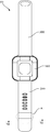
- FIG. 1 is a top view of a wearable apparatus before being worn according to an embodiment of the present disclosure.
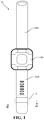
- FIG. 2 is a schematic structural diagram of a dial in FIG. 1 .
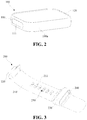
- FIG. 3 is a schematic structural diagram of a first watch strap in FIG. 1 according to an embodiment of the present disclosure.
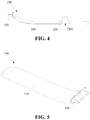
- FIG. 4 is a side view of the first watch strap in FIG. 3 ;
- FIG. 5 is a schematic structural diagram of a second watch strap in FIG. 1 according to an embodiment of the present disclosure
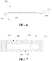
- FIG. 6 is a side view of the second watch strap in FIG. 5 ;
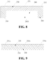
- FIG. 8 is a schematic structural diagram of the first strap body defining a hole in the wearable apparatus of FIG. 7 .
- FIG. 9 is a schematic cross-sectional view taken along the section line VII-VII at A in FIG. 1 according to an embodiment of the present disclosure.
- FIG. 11 is an enlarged schematic view at A in FIG. 1 according to an embodiment of the present disclosure.
- a watch strap assembly could include a first watch strap and a second watch strap.
- the first watch strap could include a first strap body and a confining strap.
- the confining strap could be integrally formed with the first strap body.
- the confining strap could be located between two opposite ends of the first strap body, and the confining strap could be capable of defining a channel with the first strap body between the confining strap and the first strap body.
- the second watch strap could include a second strap body, an end of the second strap body could be capable of passing through the channel and being secured to the first strap body.
- the confining strap may be located between two opposite ends in a length direction of the first strap body and the confining strap may extend across two opposite ends in a width direction of the first strap body.
- the confining strap may include a top edge portion, the top edge portion could include a first segment, a middle segment and a second segment connected in sequence along a width direction of the first watch strap. The first segment and the second segment could be both connected to the first strap body.
- the middle segment is capable of attaching the first strap body, and when the second strap body passes through the middle segment, the middle segment could be upheld and separate from the first strap body and could define the channel.
- the confining strap could include a top edge portion and side edge portions connected to two ends of the top edge portion.
- the top edge portion could be opposite to and spaced from the first strap body in a thickness direction of the first strap body.
- the side edge portions could be connected between the top edge portion and the first strap body.
- the top edge portion, the side edge portions and the first strap body could define the channel.
- the first strap body could define a hole communicating with the channel.
- a first groove and a second groove spaced apart from each other could be defined on the first strap body along the width direction of the first strap body.
- the first groove could be closed in the circumferential direction
- the second groove could be closed in the circumferential direction.
- a portion between the first groove and the second groove could form the confining strap.
- the confining strap could be capable of being upheld to define the channel.
- a port of the channel could be an opening of the first groove and the other port of the channel could be an opening of the second groove.
- the material of the first strap body could include at least one of silica gel, plastic, rubber, leather, and fiber.
- the material of the second strap body could include at least one of silica gel, plastic, rubber, leather, and fiber.
- an end of the second strap body could be capable of passing through the channel and being secured to the first strap body by magnetic attraction.
- the first strap body could define a catch groove
- the second strap body could be provided with a buckle.
- An end of the second strap body could be capable of passing through the channel from a side of the confining strap away from the catch groove, thus the buckle could be engaged in the catch groove.
- the first strap body could be provided with a buckle
- the second strap body could define a catch groove
- an end of the second strap body could be capable of passing through the channel from a side of the confining strap away from the buckle, thus the buckle could be engaged in the catch groove.
- the amount of the catch groove could be more than one, a plurality of the catch grooves could be defined at intervals along a length direction of the first watch strap; or a plurality of the catch grooves could be defined at intervals along a length direction of the second watch strap.
- a wearable apparatus could be provided.
- the wearable apparatus could include a dial and the above-mentioned watch strap assembly.
- the dial could include a first side wall and a second side wall arranged opposite to each other.
- the first watch strap could include a first mounting portion at one end of the first strap body, the second watch strap could include a second mounting portion at one end of the second strap body.
- the first mounting portion could connect with the first side wall, the second mounting portion could connect with the second side wall.
- one end of the second strap body away from the second mounting portion could be capable of passing through the channel from one side of the confining strap away from the mounting portion and defining a receiving space.
- the confining strap could protrude from one side of the first strap body facing away from the receiving space.
- a watch strap could be provided.
- the watch strap could include a first strap body and a confining strap.
- the confining strap could be integrally formed with the first strap body.
- the confining strap could be located between two opposite ends of the first strap body, and the confining strap could be capable of defining a channel with the first strap body between the confining strap and the first strap body. The channel extends along the length direction of the watch strap.
- the confining strap could include a top edge portion.
- the top edge portion could include a first segment, a middle segment and a second segment connected in sequence along a width direction of the first watch strap.
- the first segment and the second segment could be both connected to the first strap body.
- the middle segment could be capable of attaching the first strap body, and the middle segment could be capable of being upheld and separate from the first strap body and defining the channel.
- the confining strap could include a top edge portion and side edge portions connected to two ends of the top edge portion.
- the top edge portion could be opposite to and spaced from the first strap body in a thickness direction of the first strap body.
- the side edge portions could be connected between the top edge portion and the first strap body.
- the top edge portion, the side edge portions and the first strap body could define the channel.
- a first groove and a second groove spaced apart from each other could be defined on the first strap body along the width direction of the first strap body.
- the first groove could be closed in the circumferential direction
- the second groove could be closed in the circumferential direction.
- a portion between the first groove and the second groove could form the confining strap.
- the confining strap could be capable of being upheld to define the channel.
- a port of the channel could be an opening of the first groove and the other port of the channel could be an opening of the second groove.
- the watch strap could include a first mounting portion at one end of the first band body.
- a buckle could be provided on the first strap body between the first mounting portion and the confining strap or a catch groove could be defined on the first strap body between the first mounting portion and the confining strap.
- a hole may be defined in the first strap body under the bridge and communicated with the space.
- one of the first and second fasteners may include a plurality of apertures
- the other one of the first and second fasteners may include a buckle.
- the buckle When the second strap body extends through the space under the bridge, the buckle may be engaged in one of the apertures.
- an extending direction of the first strap body may be substantially perpendicular to an extending direction of the bridge.
- the bridge and the first strap may be made of a single piece.
- a plurality of apertures may be defined in the first strap body and located between the dial and the flexible confining strap.
- the second strap body may include a buckle configured to be engaged in the apertures after the second strap extends through the space.
- the dial 100 may include a first side wall 110 and a second side wall 120 arranged opposite to each other.
- the first side wall 110 may define a first mounting groove 111 and the second side wall 120 may define a second mounting groove.
- the first side wall 110 and the second side wall 120 could be regarded as a part of the side peripheral face 100 a of the dial 100 .
- the dial 100 could define the first mounting groove 111 and the second mounting groove on its side peripheral face 100 a.
- the second watch strap 300 may be connected to the second side wall 120 of the dial 100 .
- the second watch strap 300 may include a second strap body 310 and a second mounting portion 320 connected to one end of the second strap body 310 .
- the second mounting portion 320 could be inserted in the second mounting groove, so as to realize a detachable connection between the second watch strap 300 and the dial 100 .
- the second mounting portion 320 may be inserted in the second mounting groove and then could be locked in the mounting groove through a fastener such as a spring bar.
- the second mounting portion 320 could be omitted.
- the second strap body 310 could be connected to the second side wall 120 of the dial 100 .
- the second strap body 310 may be bonded to the second side wall 120 of the dial 100 by adhesion.
- Both the first watch strap 200 and the second watch strap 300 could be bent and deformed under external force.
- the first watch strap 200 and the second watch strap 300 may both be flexible straps.
- the materials of the first strap body 210 and the second strap body 310 may both be flexible materials.
- the flexible material may include, but be not limited to, at least one of silica gel, plastic, rubber, leather and fiber.
- the first watch strap 200 and the second watch strap 300 could be buckled with each other after being bent and deformed to form a ring-shaped receiving space, thus the wearable apparatus 10 could be worn to a joint such as a wrist of a human body.
- the first watch strap 200 may include a confining strap 230 which may be called a bridge 230 .
- the confining strap 230 is located between two opposite ends in a length direction of the first strap body 210 .
- the confining strap 230 and the first strap body 210 may be integrally formed.
- the confining strap 230 and the first strap body 210 could be integrally made by injection molding.
- a channel 240 could be defined between the confining strap 230 and the first strap body 210 .
- the channel 240 may extend along the length direction of the first watch strap 200 .
- the confining strap 230 may protrude from a side of the first strap body 210 facing away from the receiving space.
- the first strap body 210 could define a catch groove or aperture 250 , which is located between the first mounting portion 220 and the confining strap 230 . That is, the catch groove 250 could be located in an extending direction of the channel 240 . As shown in FIGS.
- a buckle 350 may be provided on an end of the second strap body 310 away from the second mounting portion 320 , and the end of the second strap body 310 provided with the buckle 350 could pass through the channel 240 from a side of the confining strap 230 away from the catch groove 250 , so that the buckle 350 is engaged in the catch groove 250 , thus the first watch strap 200 and the second watch strap 300 could be fastened to each other.
- the buckle 350 could be provided on the first strap body 210 between the first mounting portion 220 and the confining strap 230 , and the second strap body 310 could define a catch groove or aperture on an end away from the second mounting portion 320 .
- the amount of the above-mentioned catch grooves 250 may be more than one.
- the multiple catch grooves 250 could be arranged at intervals along the length direction of the first watch strap 200 .
- the user could adjust the length of the second strap body 310 passing through the channel 240 according to the size of his/her wrist, so that the buckle 350 is engaged in the most suitable catch groove 250 to ensure that the user feels comfort after wearing the apparatus 10 .
- the multiple catch grooves 250 may also be defined in the second strap body 310 .
- the second strap body 310 may also be fixed to the first strap body 210 through magnetic attraction.
- a first magnetic element may be embedded in the first strap body 210
- a second magnetic element may be embedded in the second strap body 310 .
- the first magnetic element could be an electromagnet or a permanent magnet.
- the second magnetic element could be an electromagnet or a permanent magnet.
- the magnetic directions of the first magnetic element and the second magnetic element are opposite to each other.
- the second strap body 310 could be fixed to the first strap body 210 by magnetic attraction between the second magnetic element and the first magnetic element.
- the first magnetic elements may be arranged at intervals along the length direction of the first watch strap 200 . It should be noted that, one of the first magnetic element and the second magnetic element could be replaced by a metal piece.
- an end of the second strap body 310 could pass through the channel 240 from the side of the confining strap 230 away from the catch groove 250 , so that the buckle 350 is engaged in a catch groove 250 to realize the fixing connection between the first watch strap 200 and the second watch strap 300 , thus the wearable apparatus 10 could be worn on a joint such as a wrist of the user.
- the confining strap 230 could force the portion of the second strap body 310 without the buckle 350 to attach the first strap body 210 , to prevent the separation between part of the second strap body 310 and the first strap body 210 .
- the confining strap 230 is integrally formed with the first strap body 210 , the processing of the first watch strap 200 could be facilitated, and the fabrication cost could be reduced.
- the confining strap 230 could always be held at a fixed position on the first strap body 210 and could not slide with respect to the first strap body 210 , the degree of attachment between the second strap body 310 and the first strap body 210 after the second strap body 310 passes through the channel 240 is increased, thus the user's experience is enhanced.
- the confining strap 230 and the first strap body 210 could define the channel 240 in various ways.
- the confining strap 230 may include a top edge portion 231 and side edge portions 232 connected to two opposite sides of the top edge portion 231 .
- the top edge portion 231 is opposite to and spaced from the first strap body 210 in a thickness direction of the first strap body 210 .
- the side edge portions 232 may be connected between the top edge portion 231 and the first strap body 210 .
- the top edge portion 231 , the side edge portions 232 , and the first strap body 210 may collectively define the above-mentioned channel 240 .
- the first strap body 210 may define a hole 2101 communicating with the channel 240 .
- the buckle 350 when the buckle 350 is detached from the catch groove 250 (for example, when the buckle 350 is not engaged firmly with the catch groove 250 and the buckle 350 is detached from the catch groove 250 , or after the user wears the wearable apparatus 10 on a joint such as a wrist, the user's strenuous exercise may cause the buckle 350 to detach from the catch groove 250 ), the second strap body 310 would not be easily out from the confining strap 230 and separate from the first strap body 210 . In other words, the wearable apparatus 10 would not be easily detached from the joint such as the wrist.
- the hole 2101 could prevent the second strap body 310 with the buckle 350 from continuing to exit.
- the hole 2101 could also reduce material expense of the first watch strap 200 and decrease the manufacturing cost.
- the second strap body 310 when the second strap body 310 passes through the channel 240 , the second strap body 310 could abut against the inner wall of the confining strap 230 and the confining strap 230 could be stretched.
- the cross-sectional area of the channel 240 defined by the confining strap 230 may be less than the cross-sectional area of the second strap body 310 .
- the confining strap 230 could accumulate elastic force.
- the confining strap 230 could wrap the second strap body 310 in the channel 240 with the elastic force.
- FIG. 3 and 4 depict schematic structural diagrams of the first watch strap 200 , wherein, the confining strap 230 of the first watch strap 200 is in a state when the confining strap 230 is being stretched after the second strap body 310 passes through the channel 240 .
- the confining strap 230 could collapse under the effect of the elastic force. It should be appreciated that, in other embodiments, the channel 240 defined between the confining strap 230 and the first strap body 210 could accommodate the second strap body 310 .
- the cross-sectional area of the channel 240 defined between the confining strap 230 and the first strap body 210 is larger than the cross-sectional area of the second strap body 310 .
- the side edge portions 232 of the confining strap 230 may be omitted.
- the confining strap 230 may include a top edge portion 231 .
- the top edge portion 231 could include a first segment 231 a, a middle segment 231 b and a second segment 231 c connected in sequence along the width extension direction of the first watch strap 200 .
- the first segment 231 a and the second segment 231 c may both be connected to the first strap body 210 .
- the first segment 231 a and the second segment 231 c may both be extensions from the first strap body 210 .
- the middle segment 231 b could attach the first strap body 210 . As shown in FIG.
- the middle segment 231 b could be upheld to be spaced apart from the first strap body 210 so as to define the above-mentioned channel 240 .
- the second strap body 310 could uphold the middle segment 231 b.
- the middle segment 231 b could accumulate elastic force.
- the middle segment 231 b releases the elastic force, the middle segment 231 b could attach the first strap body 210 once again.
- the confining strap 230 When the confining strap 230 is upheld, the confining strap 230 could accumulate the elastic force. When the confining strap 230 releases the elastic force, the confining strap 230 could collapse. An outer face of the collapsed confining strap 230 may be flush with an outer face of the first strap body 210 . In some embodiments, the first groove 2102 and the second groove 2103 may also be scribed lines.
- the watch strap may include a first strap body 210 and a confining strap 230 .
- the confining strap 230 could be integrally formed with the first strap body 210 .
- the confining strap 230 could be located between two opposite ends in a length direction of the first strap body 210 , and a channel 240 could be defined between the confining strap 230 and the first strap body 210 .
- the channel 240 extends along the length direction of the watch strap.
- the strap of the embodiments of the present disclosure could be produced separately and applied to the wearable apparatus 10 , and the structural characteristics of the strap could be exactly the same as those of the first watch strap 200 in the embodiments of the present disclosure, and are thus not detailed hereafter.
Landscapes
- Physics & Mathematics (AREA)
- General Physics & Mathematics (AREA)
- Purses, Travelling Bags, Baskets, Or Suitcases (AREA)
- Buckles (AREA)
Abstract
Description
- The present application claims the benefits of and priority to Chinese Patent Application No. 201920971782.1, filed on Jun. 25, 2019, the entire contents of which are hereby incorporated by reference in their entireties.
- The present disclosure relates to wearable apparatus technique, and in particular to a watch strap assembly, a watch strap and a wearable apparatus.
- In related technologies, the watch strap of a wearable apparatus such as a smart watch and a smart bracelet could be adjusted in length. For example, the length of the watch strap could be adjusted through the use of a pin buckle and a fixing orifice to allow a user to wear the wearable apparatus on a joint of the user (such as a wrist of the user) in a preferred fashion. However, the watch strap whose length is adjustable is relatively expensive to manufacture, and the wearable apparatus suffers a risk of not being worn firmly after a user wears it.
- A watch strap assembly in accordance with an embodiment in the present disclosure may include a first watch strap and a second watch strap. The first watch strap may include a first strap body and a confining strap. The confining strap may be integrally formed with the first strap body. The confining strap may be located between two opposite ends of the first strap body. A channel may be defined between the confining strap and the first strap body. The second watch strap may include a second strap body. An end of the second strap body may be capable of passing through the channel and being secured to the first strap body.
- A watch strap for a wristwatch in accordance with an embodiment in the present disclosure may include a first strap body and a second strap body. The first strap body may have a first end and a second end along a length direction. The first strap may include a bridge located between the first end and the second end and a first fastener located between the first end and the bridge. The second strap body may be configured to extend through a space under the bridge. The second strap body may include a second fastener. The second fastener may be configured to cooperate with the first fastener when the second strap body extends through the space under the bridge.
- A wearable apparatus in accordance with an embodiment in the present disclosure may include a dial, a first strap and a second strap. The dial may have a first side and a second side. The first strap may include an elongated first strap body connectable to the first side of the dial, and a flexible confining strap arranged on and be in contact with the first strap body. The second strap may include an elongated second strap body connectable to the second side of the dial. There may be a space generated between the flexible confining strap and the first strap body when the second strap engages with the first strap, such that the second strap may extend through the space.
- In order to illustrate the technical solutions in the embodiments of the present disclosure or the prior art more clearly, the drawings required in the description of the embodiments or the prior art will be briefly introduced below. Obviously, the drawings in the following description are merely some embodiments of the present disclosure. For those of ordinary skill in the art, other drawings could be obtained based on these drawings without any more creative work.
-
FIG. 1 is a top view of a wearable apparatus before being worn according to an embodiment of the present disclosure. -
FIG. 2 is a schematic structural diagram of a dial inFIG. 1 . -
FIG. 3 is a schematic structural diagram of a first watch strap inFIG. 1 according to an embodiment of the present disclosure. -
FIG. 4 is a side view of the first watch strap inFIG. 3 ; -
FIG. 5 is a schematic structural diagram of a second watch strap inFIG. 1 according to an embodiment of the present disclosure; -
FIG. 6 is a side view of the second watch strap inFIG. 5 ; -
FIG. 7 is a schematic cross-sectional view taken along the section line VII-VII at A inFIG. 1 according to an embodiment of the present disclosure. -
FIG. 8 is a schematic structural diagram of the first strap body defining a hole in the wearable apparatus ofFIG. 7 . -
FIG. 9 is a schematic cross-sectional view taken along the section line VII-VII at A inFIG. 1 according to an embodiment of the present disclosure. -
FIG. 10 is a schematic structural diagram of a wearable apparatus after a middle segment inFIG. 9 is stretched. -
FIG. 11 is an enlarged schematic view at A inFIG. 1 according to an embodiment of the present disclosure. - In order to facilitate understanding of the present disclosure, the present disclosure will be detailed more thoroughly with reference to corresponding drawings. The drawings show the preferred embodiments of the present disclosure. However, the present disclosure could be embodied in various forms and is not limited to the embodiments described herein. Rather, these embodiments are presented to provide a thorough and comprehensive understanding of the present disclosure.
- According to a first aspect of the present disclosure, a watch strap assembly is provided. The watch strap assembly could include a first watch strap and a second watch strap. The first watch strap could include a first strap body and a confining strap. The confining strap could be integrally formed with the first strap body. The confining strap could be located between two opposite ends of the first strap body, and the confining strap could be capable of defining a channel with the first strap body between the confining strap and the first strap body. The second watch strap could include a second strap body, an end of the second strap body could be capable of passing through the channel and being secured to the first strap body.
- In some embodiments, the confining strap may be located between two opposite ends in a length direction of the first strap body and the confining strap may extend across two opposite ends in a width direction of the first strap body. The confining strap may include a top edge portion, the top edge portion could include a first segment, a middle segment and a second segment connected in sequence along a width direction of the first watch strap. The first segment and the second segment could be both connected to the first strap body. The middle segment is capable of attaching the first strap body, and when the second strap body passes through the middle segment, the middle segment could be upheld and separate from the first strap body and could define the channel.
- In some embodiments, the confining strap could include a top edge portion and side edge portions connected to two ends of the top edge portion. The top edge portion could be opposite to and spaced from the first strap body in a thickness direction of the first strap body. The side edge portions could be connected between the top edge portion and the first strap body. The top edge portion, the side edge portions and the first strap body could define the channel.
- In some embodiments, the first strap body could define a hole communicating with the channel.
- In some embodiments, when the second strap body passes through the channel, the second strap body could abut against an inner wall of the confining strap and uphold the confining strap, the confining strap could accumulate elastic force. When the second strap body exits from the channel, the confining strap could collapse under the effect of the elastic force.
- In some embodiments, a first groove and a second groove spaced apart from each other could be defined on the first strap body along the width direction of the first strap body. The first groove could be closed in the circumferential direction, the second groove could be closed in the circumferential direction. A portion between the first groove and the second groove could form the confining strap. The confining strap could be capable of being upheld to define the channel. A port of the channel could be an opening of the first groove and the other port of the channel could be an opening of the second groove.
- In some embodiments, the material of the first strap body could include at least one of silica gel, plastic, rubber, leather, and fiber. The material of the second strap body could include at least one of silica gel, plastic, rubber, leather, and fiber.
- In some embodiments, an end of the second strap body could be capable of passing through the channel and being secured to the first strap body by magnetic attraction.
- In some embodiments, the first strap body could define a catch groove, the second strap body could be provided with a buckle. An end of the second strap body could be capable of passing through the channel from a side of the confining strap away from the catch groove, thus the buckle could be engaged in the catch groove. Or the first strap body could be provided with a buckle, the second strap body could define a catch groove, an end of the second strap body could be capable of passing through the channel from a side of the confining strap away from the buckle, thus the buckle could be engaged in the catch groove.
- In some embodiments, the amount of the catch groove could be more than one, a plurality of the catch grooves could be defined at intervals along a length direction of the first watch strap; or a plurality of the catch grooves could be defined at intervals along a length direction of the second watch strap.
- In some embodiments, the first watch strap could include a first mounting portion at one end of the first strap body, the catch groove or the buckle could be located between the first mounting portion and the confining strap. The second watch strap could include a second mounting portion at one end of the second strap body, the buckle or the catch groove could be located at the other end of the second strap body.
- According to a second aspect of the present disclosure, a wearable apparatus could be provided. The wearable apparatus could include a dial and the above-mentioned watch strap assembly. The dial could include a first side wall and a second side wall arranged opposite to each other. The first watch strap could include a first mounting portion at one end of the first strap body, the second watch strap could include a second mounting portion at one end of the second strap body. The first mounting portion could connect with the first side wall, the second mounting portion could connect with the second side wall.
- In some embodiments, one end of the second strap body away from the second mounting portion could be capable of passing through the channel from one side of the confining strap away from the mounting portion and defining a receiving space. When the channel is defined by the confining strap, the confining strap could protrude from one side of the first strap body facing away from the receiving space.
- According to a third aspect of the present disclosure, a watch strap could be provided. The watch strap could include a first strap body and a confining strap. The confining strap could be integrally formed with the first strap body. The confining strap could be located between two opposite ends of the first strap body, and the confining strap could be capable of defining a channel with the first strap body between the confining strap and the first strap body. The channel extends along the length direction of the watch strap.
- In some embodiments, the confining strap could include a top edge portion. The top edge portion could include a first segment, a middle segment and a second segment connected in sequence along a width direction of the first watch strap. The first segment and the second segment could be both connected to the first strap body. The middle segment could be capable of attaching the first strap body, and the middle segment could be capable of being upheld and separate from the first strap body and defining the channel.
- In some embodiments, the confining strap could include a top edge portion and side edge portions connected to two ends of the top edge portion. The top edge portion could be opposite to and spaced from the first strap body in a thickness direction of the first strap body. The side edge portions could be connected between the top edge portion and the first strap body. The top edge portion, the side edge portions and the first strap body could define the channel.
- In some embodiments, the first strap body could define a hole communicating with the channel.
- In some embodiments, a first groove and a second groove spaced apart from each other could be defined on the first strap body along the width direction of the first strap body. The first groove could be closed in the circumferential direction, the second groove could be closed in the circumferential direction. A portion between the first groove and the second groove could form the confining strap. The confining strap could be capable of being upheld to define the channel. A port of the channel could be an opening of the first groove and the other port of the channel could be an opening of the second groove.
- In some embodiments, the material of the first strap body could include at least one of silica gel, plastic, rubber, leather, and fiber.
- In some embodiments, the watch strap could include a first mounting portion at one end of the first band body. A buckle could be provided on the first strap body between the first mounting portion and the confining strap or a catch groove could be defined on the first strap body between the first mounting portion and the confining strap.
- According to another aspect of the present disclosure, a watch strap for a wristwatch is provided. The watch strap for a wristwatch may include a first strap body and a second strap body. The first strap body may have a first end and a second end along a length direction. The first strap may include a bridge located between the first end and the second end and a first fastener located between the first end and the bridge. The second strap body may be configured to extend through a space under the bridge. The second strap body may include a second fastener. The second fastener may be configured to cooperate with the first fastener when the second strap body extends through the space under the bridge.
- In some embodiments, the space may be defined between the bridge and the first strap body under the bridge.
- In some embodiments, a hole may be defined in the first strap body under the bridge and communicated with the space.
- In some embodiments, one of the first and second fasteners may include a plurality of apertures, the other one of the first and second fasteners may include a buckle. When the second strap body extends through the space under the bridge, the buckle may be engaged in one of the apertures.
- In some embodiments, an extending direction of the first strap body may be substantially perpendicular to an extending direction of the bridge.
- In some embodiments, the bridge and the first strap may be made of a single piece.
- According to another aspect of the present disclosure, a wearable apparatus is provided. The wearable apparatus may include a dial, a first strap and a second strap. The dial may have a first side and a second side. The first strap may include an elongated first strap body connectable to the first side of the dial, and a flexible confining strap arranged on and be in contact with the first strap body. The second strap may include an elongated second strap body connectable to the second side of the dial. There may be a space generated between the flexible confining strap and the first strap body when the second strap engages with the first strap, such that the second strap may extend through the space.
- In some embodiments, a plurality of apertures may be defined in the first strap body and located between the dial and the flexible confining strap.
- In some embodiments, the second strap body may include a buckle configured to be engaged in the apertures after the second strap extends through the space.
- With reference to
FIG. 1 , in some embodiments, a wristwatch (including a smart watch and a mechanical watch) is taken as an example to illustrate awearable apparatus 10. Thewearable apparatus 10 may include adial 100 with afirst watch strap 200 and asecond watch strap 300. Thefirst watch strap 200 may connect with a side of thedial 100, and thesecond watch strap 300 may connect with an opposite side of thedial 100. Thefirst watch strap 200 and thesecond watch strap 300 may cooperate with each other to enable a user's wearing operation on thewearable apparatus 10 like a wristwatch. It should be appreciated that, in other embodiments, thewearable apparatus 10 may also be a smart bracelet or a smart armlet, which is not limited herein. - As shown in
FIG. 2 , thedial 100 may include afirst side wall 110 and asecond side wall 120 arranged opposite to each other. In some embodiments, thefirst side wall 110 may define a first mountinggroove 111 and thesecond side wall 120 may define a second mounting groove. It should be noted that, thefirst side wall 110 and thesecond side wall 120 could be regarded as a part of the sideperipheral face 100 a of thedial 100. In other words, thedial 100 could define the first mountinggroove 111 and the second mounting groove on its sideperipheral face 100 a. - The
first watch strap 200 may be connected to thefirst side wall 110 of thedial 100. In some embodiments, referring toFIGS. 3 and 4 , thefirst watch strap 200 may include afirst strap body 210 and a first mountingportion 220 connected to one end of thefirst strap body 210. The first mountingportion 220 could be inserted in the first mountinggroove 111, so as to realize a detachable connection between thefirst watch strap 200 and thedial 100. For example, the first mountingportion 220 may be inserted in the first mountinggroove 111 and then could be locked in the mountinggroove 111 through a fastener such as a spring bar. It should be appreciated that, in other embodiments, the first mountingportion 220 could be omitted. In these cases, thefirst strap body 210 could be connected to thefirst side wall 110 of thedial 100. For example, thefirst strap body 210 could be bonded to thefirst side wall 110 of thedial 100 by adhesion. - The
second watch strap 300 may be connected to thesecond side wall 120 of thedial 100. In some embodiments, referring toFIGS. 5 and 6 , thesecond watch strap 300 may include asecond strap body 310 and a second mountingportion 320 connected to one end of thesecond strap body 310. Thesecond mounting portion 320 could be inserted in the second mounting groove, so as to realize a detachable connection between thesecond watch strap 300 and thedial 100. For example, the second mountingportion 320 may be inserted in the second mounting groove and then could be locked in the mounting groove through a fastener such as a spring bar. It should be appreciated that, in other embodiments, the second mountingportion 320 could be omitted. In these cases, thesecond strap body 310 could be connected to thesecond side wall 120 of thedial 100. For example, thesecond strap body 310 may be bonded to thesecond side wall 120 of thedial 100 by adhesion. - Both the
first watch strap 200 and thesecond watch strap 300 could be bent and deformed under external force. For example, thefirst watch strap 200 and thesecond watch strap 300 may both be flexible straps. In these cases, the materials of thefirst strap body 210 and thesecond strap body 310 may both be flexible materials. The flexible material may include, but be not limited to, at least one of silica gel, plastic, rubber, leather and fiber. Thefirst watch strap 200 and thesecond watch strap 300 could be buckled with each other after being bent and deformed to form a ring-shaped receiving space, thus thewearable apparatus 10 could be worn to a joint such as a wrist of a human body. - In some embodiments, as shown in
FIG. 3 andFIG. 4 , thefirst watch strap 200 may include a confiningstrap 230 which may be called abridge 230. The confiningstrap 230 is located between two opposite ends in a length direction of thefirst strap body 210. The confiningstrap 230 and thefirst strap body 210 may be integrally formed. For example, the confiningstrap 230 and thefirst strap body 210 could be integrally made by injection molding. Achannel 240 could be defined between the confiningstrap 230 and thefirst strap body 210. In some embodiments, thechannel 240 may extend along the length direction of thefirst watch strap 200. When thechannel 240 is defined by the confiningstrap 230, the confiningstrap 230 may protrude from a side of thefirst strap body 210 facing away from the receiving space. - An end of the
second strap body 310 away from the second mountingportion 320 could pass through thechannel 240 from a side of the confiningstrap 230 away from the first mountingportion 220 and be fixed to thefirst strap body 210. In some embodiments, thefirst strap body 210 could define a catch groove oraperture 250, which is located between the first mountingportion 220 and the confiningstrap 230. That is, thecatch groove 250 could be located in an extending direction of thechannel 240. As shown inFIGS. 5 and 6 , abuckle 350 may be provided on an end of thesecond strap body 310 away from the second mountingportion 320, and the end of thesecond strap body 310 provided with thebuckle 350 could pass through thechannel 240 from a side of the confiningstrap 230 away from thecatch groove 250, so that thebuckle 350 is engaged in thecatch groove 250, thus thefirst watch strap 200 and thesecond watch strap 300 could be fastened to each other. - It should be appreciated that, in other embodiments, the
buckle 350 could be provided on thefirst strap body 210 between the first mountingportion 220 and the confiningstrap 230, and thesecond strap body 310 could define a catch groove or aperture on an end away from the second mountingportion 320. It should be noted that, the amount of the above-mentionedcatch grooves 250 may be more than one. For example, whenmultiple catch grooves 250 are defined in thefirst strap body 210, themultiple catch grooves 250 could be arranged at intervals along the length direction of thefirst watch strap 200. In these cases, the user could adjust the length of thesecond strap body 310 passing through thechannel 240 according to the size of his/her wrist, so that thebuckle 350 is engaged in the mostsuitable catch groove 250 to ensure that the user feels comfort after wearing theapparatus 10. Of course, in other embodiments, themultiple catch grooves 250 may also be defined in thesecond strap body 310. - In other embodiments, in addition to the buckle-connection between the
buckle 350 and thecatch groove 250, after an end of thesecond strap body 310 passes through thechannel 240, thesecond strap body 310 may also be fixed to thefirst strap body 210 through magnetic attraction. For example, a first magnetic element may be embedded in thefirst strap body 210, and a second magnetic element may be embedded in thesecond strap body 310. The first magnetic element could be an electromagnet or a permanent magnet. The second magnetic element could be an electromagnet or a permanent magnet. The magnetic directions of the first magnetic element and the second magnetic element are opposite to each other. Thesecond strap body 310 could be fixed to thefirst strap body 210 by magnetic attraction between the second magnetic element and the first magnetic element. In some embodiments, the first magnetic elements may be arranged at intervals along the length direction of thefirst watch strap 200. It should be noted that, one of the first magnetic element and the second magnetic element could be replaced by a metal piece. - In the above-mentioned
wearable apparatus 10, an end of thesecond strap body 310 could pass through thechannel 240 from the side of the confiningstrap 230 away from thecatch groove 250, so that thebuckle 350 is engaged in acatch groove 250 to realize the fixing connection between thefirst watch strap 200 and thesecond watch strap 300, thus thewearable apparatus 10 could be worn on a joint such as a wrist of the user. The confiningstrap 230 could force the portion of thesecond strap body 310 without thebuckle 350 to attach thefirst strap body 210, to prevent the separation between part of thesecond strap body 310 and thefirst strap body 210. On the one hand, since the confiningstrap 230 is integrally formed with thefirst strap body 210, the processing of thefirst watch strap 200 could be facilitated, and the fabrication cost could be reduced. On the other hand, since the confiningstrap 230 could always be held at a fixed position on thefirst strap body 210 and could not slide with respect to thefirst strap body 210, the degree of attachment between thesecond strap body 310 and thefirst strap body 210 after thesecond strap body 310 passes through thechannel 240 is increased, thus the user's experience is enhanced. - The confining
strap 230 and thefirst strap body 210 could define thechannel 240 in various ways. - In some embodiments, as shown in
FIG. 7 , the confiningstrap 230 may include atop edge portion 231 andside edge portions 232 connected to two opposite sides of thetop edge portion 231. Thetop edge portion 231 is opposite to and spaced from thefirst strap body 210 in a thickness direction of thefirst strap body 210. Theside edge portions 232 may be connected between thetop edge portion 231 and thefirst strap body 210. Thetop edge portion 231, theside edge portions 232, and thefirst strap body 210 may collectively define the above-mentionedchannel 240. In some embodiments, as shown inFIG. 8 , thefirst strap body 210 may define ahole 2101 communicating with thechannel 240. In this way, when thebuckle 350 is detached from the catch groove 250 (for example, when thebuckle 350 is not engaged firmly with thecatch groove 250 and thebuckle 350 is detached from thecatch groove 250, or after the user wears thewearable apparatus 10 on a joint such as a wrist, the user's strenuous exercise may cause thebuckle 350 to detach from the catch groove 250), thesecond strap body 310 would not be easily out from the confiningstrap 230 and separate from thefirst strap body 210. In other words, thewearable apparatus 10 would not be easily detached from the joint such as the wrist. This is because, during the process thesecond strap body 310 exiting from the confiningstrap 230, thesecond strap body 310 will press thebuckle 350 to be engaged in thehole 2101 under the resistance of thetop edge portion 231. Therefore, thehole 2101 could prevent thesecond strap body 310 with thebuckle 350 from continuing to exit. On the other hand, thehole 2101 could also reduce material expense of thefirst watch strap 200 and decrease the manufacturing cost. - In some embodiments, when the
second strap body 310 passes through thechannel 240, thesecond strap body 310 could abut against the inner wall of the confiningstrap 230 and the confiningstrap 230 could be stretched. In other words, the cross-sectional area of thechannel 240 defined by the confiningstrap 230 may be less than the cross-sectional area of thesecond strap body 310. In these cases, the confiningstrap 230 could accumulate elastic force. The confiningstrap 230 could wrap thesecond strap body 310 in thechannel 240 with the elastic force.FIGS. 3 and 4 depict schematic structural diagrams of thefirst watch strap 200, wherein, the confiningstrap 230 of thefirst watch strap 200 is in a state when the confiningstrap 230 is being stretched after thesecond strap body 310 passes through thechannel 240. After thesecond strap body 310 exits from thechannel 240, as shown inFIG. 8 , the confiningstrap 230 could collapse under the effect of the elastic force. It should be appreciated that, in other embodiments, thechannel 240 defined between the confiningstrap 230 and thefirst strap body 210 could accommodate thesecond strap body 310. That is, the cross-sectional area of thechannel 240 defined between the confiningstrap 230 and thefirst strap body 210 is larger than the cross-sectional area of thesecond strap body 310. When thefirst watch strap 200 and thesecond watch strap 300 mate with each other, the confiningstrap 230 does not need to be elastically deformed. - In some embodiments, the
side edge portions 232 of the confiningstrap 230 may be omitted. In these cases, the confiningstrap 230 may include atop edge portion 231. As shown inFIG. 9 , thetop edge portion 231 could include afirst segment 231 a, amiddle segment 231 b and asecond segment 231 c connected in sequence along the width extension direction of thefirst watch strap 200. Thefirst segment 231 a and thesecond segment 231 c may both be connected to thefirst strap body 210. It may also be appreciated that, thefirst segment 231 a and thesecond segment 231 c may both be extensions from thefirst strap body 210. Themiddle segment 231 b could attach thefirst strap body 210. As shown inFIG. 10 , themiddle segment 231 b could be upheld to be spaced apart from thefirst strap body 210 so as to define the above-mentionedchannel 240. For example, after thesecond strap body 310 passes through thechannel 240, thesecond strap body 310 could uphold themiddle segment 231 b. When themiddle segment 231 b is upheld, themiddle segment 231 b could accumulate elastic force. When themiddle segment 231 b releases the elastic force, themiddle segment 231 b could attach thefirst strap body 210 once again. - In some embodiments, as shown in
FIG. 11 , thefirst groove 2102 and thesecond groove 2103 spaced apart from each other are defined on thefirst strap body 210. Thefirst groove 2102 and thesecond groove 2103 may both be along the width direction of thefirst strap body 210. Thefirst groove 2102 may be closed in the circumferential direction. Thesecond groove 2103 may be closed in the circumferential direction. A portion between thefirst groove 2102 and thesecond groove 2103 may form the confiningstrap 230. The confiningstrap 230 could be upheld to define achannel 240. One port of thechannel 240 may be an opening of thefirst groove 2102 and the other port of thechannel 240 may be an opening of thesecond groove 2103. When the confiningstrap 230 is upheld, the confiningstrap 230 could accumulate the elastic force. When the confiningstrap 230 releases the elastic force, the confiningstrap 230 could collapse. An outer face of the collapsed confiningstrap 230 may be flush with an outer face of thefirst strap body 210. In some embodiments, thefirst groove 2102 and thesecond groove 2103 may also be scribed lines. In these cases, when the confiningstrap 230 is in a state of not being upheld, that is, thefirst watch strap 200 does not mate with thesecond watch strap 300, sides of the confiningstrap 230 adjacent to thefirst groove 2102 and thesecond groove 2103 could be in contact with thefirst strap body 210, and the outer face of the confiningstrap 230 could be flush with the outer face of thefirst strap body 210. - Another aspect of the present disclosure provides a watch strap. The watch strap may include a
first strap body 210 and a confiningstrap 230. The confiningstrap 230 could be integrally formed with thefirst strap body 210. The confiningstrap 230 could be located between two opposite ends in a length direction of thefirst strap body 210, and achannel 240 could be defined between the confiningstrap 230 and thefirst strap body 210. Thechannel 240 extends along the length direction of the watch strap. It should be noted that, the strap of the embodiments of the present disclosure could be produced separately and applied to thewearable apparatus 10, and the structural characteristics of the strap could be exactly the same as those of thefirst watch strap 200 in the embodiments of the present disclosure, and are thus not detailed hereafter. - The technical features of the embodiments described above could be arbitrarily combined. For the sake of brevity, all the possible combinations of the technical features are not enumerated and described. However, as long as there is no contradiction in the combination of these technical features, it should be considered within the scope described in this specification.
- The above-mentioned embodiments only express several implementations of the present disclosure, whose descriptions are specific and detailed, but could be construed as a limitation on the patent scope of the present disclosure. It should be noted that, for those of ordinary skill in the art, several modifications and improvements could be made without departing from the concept of the present disclosure, which all belong to the protection scope of the present disclosure. Therefore, the protection scope of this disclosure shall be subject to the appended claims.
Claims (20)
Applications Claiming Priority (2)
| Application Number | Priority Date | Filing Date | Title |
|---|---|---|---|
| CN201920971782.1 | 2019-06-25 | ||
| CN201920971782.1U CN210726884U (en) | 2019-06-25 | 2019-06-25 | Watch straps, watch strap assemblies and wearable devices |
Publications (1)
| Publication Number | Publication Date |
|---|---|
| US20200405015A1 true US20200405015A1 (en) | 2020-12-31 |
Family
ID=70804595
Family Applications (1)
| Application Number | Title | Priority Date | Filing Date |
|---|---|---|---|
| US16/886,246 Abandoned US20200405015A1 (en) | 2019-06-25 | 2020-05-28 | Watch Strap Assembly, Watch Strap and Wearable Apparatus |
Country Status (4)
| Country | Link |
|---|---|
| US (1) | US20200405015A1 (en) |
| EP (1) | EP3756502A1 (en) |
| CN (1) | CN210726884U (en) |
| WO (1) | WO2020259145A1 (en) |
Cited By (1)
| Publication number | Priority date | Publication date | Assignee | Title |
|---|---|---|---|---|
| US12133580B2 (en) | 2022-01-27 | 2024-11-05 | Samsung Electronics Co., Ltd. | Wearing member and wearable device including the same |
Families Citing this family (2)
| Publication number | Priority date | Publication date | Assignee | Title |
|---|---|---|---|---|
| CN112806679A (en) * | 2021-01-25 | 2021-05-18 | 捷开通讯(深圳)有限公司 | Watchband detachable intelligence wrist-watch |
| JP6915180B1 (en) * | 2021-01-28 | 2021-08-04 | 株式会社バンダイ | Detachable coating material housing for accessory toys and accessory toys |
Citations (40)
| Publication number | Priority date | Publication date | Assignee | Title |
|---|---|---|---|---|
| US1957274A (en) * | 1933-04-10 | 1934-05-01 | Irving R Lederer | Clasp for cord bracelets |
| US5235560A (en) * | 1992-10-16 | 1993-08-10 | Timex Corporation | Wristwatch radiotelephone |
| US6431455B1 (en) * | 1998-07-21 | 2002-08-13 | Skidata Ag | Contactless data carrier |
| US20060083115A1 (en) * | 2005-12-02 | 2006-04-20 | Ronald Lafever | Flexible band with clip-on watch |
| US20060137396A1 (en) * | 2003-06-03 | 2006-06-29 | Ka Kui Ma | Magnetic jewellery |
| US20060180000A1 (en) * | 2005-02-17 | 2006-08-17 | Suunto Oy | Strap attachment assembly |
| US20070266531A1 (en) * | 2006-02-09 | 2007-11-22 | Panduit Corp. | In-Line Cable Tie with Fixed and Hinged Locking Mechanisms |
| US20090010110A1 (en) * | 2007-07-06 | 2009-01-08 | Lawrence Chariton | Camouflage Wrist Watch Protection Apparatus |
| US20090274015A1 (en) * | 2007-09-28 | 2009-11-05 | Advance Watch Company, Ltd, D/B/A, Geneva Watch Group | Watch having a watch strap with a multi-prong closure tongue |
| US20130001263A1 (en) * | 2011-06-30 | 2013-01-03 | Advance Watch Company, Ltd., D/B/A, Geneva Watch Group | Wearable case for a mobile device |
| US20130104347A1 (en) * | 2011-10-27 | 2013-05-02 | Panduit Corp. | Bundle Spacing Device |
| US20150296929A1 (en) * | 2014-04-22 | 2015-10-22 | Merrimack River Precision Industrial Corporation | Front-release belt buckle |
| US9189023B2 (en) * | 2014-02-21 | 2015-11-17 | Cheng Uei Precision Industry Co., Ltd. | Wearable electronic device |
| US9285830B2 (en) * | 2013-02-05 | 2016-03-15 | Ross Dominique Diaz Alcazar | Interchangeable battery wearable device |
| US20160355310A1 (en) * | 2015-06-04 | 2016-12-08 | Advanced Cable Ties, Inc. | Cable Tie Adapter |
| US9581972B1 (en) * | 2015-12-18 | 2017-02-28 | Reserve Strap, Inc. | Flexible unitary charging band system |
| US20170168458A1 (en) * | 2015-12-15 | 2017-06-15 | Omega Sa | Watch bracelet |
| USD810945S1 (en) * | 2015-07-07 | 2018-02-20 | Road Id, Inc. | Identification tag for fitness device |
| USD815089S1 (en) * | 2016-08-30 | 2018-04-10 | Glide Talk Ltd. | Smart watch band |
| US20180111731A1 (en) * | 2016-10-20 | 2018-04-26 | Panduit Corp. | Cable Tie Strap and Buckle |
| USD826763S1 (en) * | 2017-03-16 | 2018-08-28 | Lung-Fei Chuang | Wristband |
| USD839121S1 (en) * | 2017-04-14 | 2019-01-29 | Fazhang LIU | Watch band |
| US20190119018A1 (en) * | 2017-10-23 | 2019-04-25 | Erik Vaclav Chmelar | Easy-to-remove cable tie |
| US20190341677A1 (en) * | 2018-05-01 | 2019-11-07 | Apple Inc. | Antenna assemblies for watch bands |
| USD881059S1 (en) * | 2018-06-20 | 2020-04-14 | Affinity Brand Partners Llc | Sport band |
| USD881060S1 (en) * | 2018-11-07 | 2020-04-14 | Bo Wang | Watchband for smart watch |
| USD883840S1 (en) * | 2020-01-03 | 2020-05-12 | Affinity Brand Partners, Llc | Watch band |
| US20200154835A1 (en) * | 2018-11-17 | 2020-05-21 | Y.F. Company Litmited | Structure of watchcase and watch strap which are fixed by pressing structure engaging with elastic pin |
| USD894033S1 (en) * | 2019-05-29 | 2020-08-25 | Qifan Zhang | Watch band |
| USD901321S1 (en) * | 2019-11-08 | 2020-11-10 | Fitbit, Inc. | Set of bands for a watch or smart watch |
| US20200405017A1 (en) * | 2019-06-25 | 2020-12-31 | Guangdong Oppo Mobile Telecommunications Corp., Ltd. | Wearable Devices, Watchband and Connector |
| US11033082B1 (en) * | 2020-04-14 | 2021-06-15 | Fitbit, Inc. | Wearable device straps and attachment hardware therefor |
| US20210201650A1 (en) * | 2019-02-26 | 2021-07-01 | Attenti Electronic Monitoring Ltd. | Protected security strap |
| USD926615S1 (en) * | 2020-09-16 | 2021-08-03 | Yaoshan Li | Watchband |
| USD938295S1 (en) * | 2014-09-08 | 2021-12-14 | Apple Inc. | Wearable device |
| US11229236B1 (en) * | 2019-08-09 | 2022-01-25 | Scott M. Arnel | Wearable vaporization system |
| US20220053892A1 (en) * | 2020-08-19 | 2022-02-24 | Masimo Corporation | Strap for a wearable device |
| USD957978S1 (en) * | 2020-12-03 | 2022-07-19 | Fitbit, Inc. | Set of bands for a fitness tracker |
| US11419396B2 (en) * | 2019-06-17 | 2022-08-23 | Guangdong Oppo Mobile Telecommunications Corp., Ltd. | Wearable device |
| US20220273177A1 (en) * | 2021-02-26 | 2022-09-01 | Elmer Tolentino | COVID Thermal Wristband |
Family Cites Families (8)
| Publication number | Priority date | Publication date | Assignee | Title |
|---|---|---|---|---|
| US2466742A (en) * | 1946-10-16 | 1949-04-12 | Nat Organ Supply Company | Strap connection |
| US3148810A (en) * | 1960-11-18 | 1964-09-15 | Sidney Steele Watch Co S A | Strap for wrist watches, etc. |
| US3994051A (en) * | 1975-09-23 | 1976-11-30 | Automatic Injection Molding, Inc. | Quick release fastener and bracket assembly for use therewith |
| CN203789297U (en) * | 2014-03-26 | 2014-08-27 | 深圳市新前途网络技术有限公司 | Intelligent wristband |
| CN204519587U (en) * | 2015-02-04 | 2015-08-05 | 汪勤伟 | The easily detachable wrist-watch of a kind of watchband |
| CN207053499U (en) * | 2017-06-01 | 2018-02-27 | 广州壹毛信息科技股份有限公司 | Electronic communication equipment based on Internet of Things |
| CN107668847A (en) * | 2017-09-15 | 2018-02-09 | 广东小天才科技有限公司 | Fastener, watchband structure, buckling method of watchband structure and intelligent watch |
| CN207704199U (en) * | 2018-01-22 | 2018-08-07 | 深圳市索野优品科技有限公司 | A kind of dismountable children's wrist-watch of water proof type watchband |
-
2019
- 2019-06-25 CN CN201920971782.1U patent/CN210726884U/en not_active Expired - Fee Related
-
2020
- 2020-05-21 WO PCT/CN2020/091648 patent/WO2020259145A1/en not_active Ceased
- 2020-05-25 EP EP20176341.4A patent/EP3756502A1/en not_active Withdrawn
- 2020-05-28 US US16/886,246 patent/US20200405015A1/en not_active Abandoned
Patent Citations (42)
| Publication number | Priority date | Publication date | Assignee | Title |
|---|---|---|---|---|
| US1957274A (en) * | 1933-04-10 | 1934-05-01 | Irving R Lederer | Clasp for cord bracelets |
| US5235560A (en) * | 1992-10-16 | 1993-08-10 | Timex Corporation | Wristwatch radiotelephone |
| US6431455B1 (en) * | 1998-07-21 | 2002-08-13 | Skidata Ag | Contactless data carrier |
| US20060137396A1 (en) * | 2003-06-03 | 2006-06-29 | Ka Kui Ma | Magnetic jewellery |
| US20060180000A1 (en) * | 2005-02-17 | 2006-08-17 | Suunto Oy | Strap attachment assembly |
| US20060083115A1 (en) * | 2005-12-02 | 2006-04-20 | Ronald Lafever | Flexible band with clip-on watch |
| US20070266531A1 (en) * | 2006-02-09 | 2007-11-22 | Panduit Corp. | In-Line Cable Tie with Fixed and Hinged Locking Mechanisms |
| US20090010110A1 (en) * | 2007-07-06 | 2009-01-08 | Lawrence Chariton | Camouflage Wrist Watch Protection Apparatus |
| US20090274015A1 (en) * | 2007-09-28 | 2009-11-05 | Advance Watch Company, Ltd, D/B/A, Geneva Watch Group | Watch having a watch strap with a multi-prong closure tongue |
| US20130001263A1 (en) * | 2011-06-30 | 2013-01-03 | Advance Watch Company, Ltd., D/B/A, Geneva Watch Group | Wearable case for a mobile device |
| US20130104347A1 (en) * | 2011-10-27 | 2013-05-02 | Panduit Corp. | Bundle Spacing Device |
| US9285830B2 (en) * | 2013-02-05 | 2016-03-15 | Ross Dominique Diaz Alcazar | Interchangeable battery wearable device |
| US9189023B2 (en) * | 2014-02-21 | 2015-11-17 | Cheng Uei Precision Industry Co., Ltd. | Wearable electronic device |
| US20150296929A1 (en) * | 2014-04-22 | 2015-10-22 | Merrimack River Precision Industrial Corporation | Front-release belt buckle |
| USD938295S1 (en) * | 2014-09-08 | 2021-12-14 | Apple Inc. | Wearable device |
| USD940582S1 (en) * | 2014-09-08 | 2022-01-11 | Apple Inc. | Wearable device |
| US20160355310A1 (en) * | 2015-06-04 | 2016-12-08 | Advanced Cable Ties, Inc. | Cable Tie Adapter |
| USD810945S1 (en) * | 2015-07-07 | 2018-02-20 | Road Id, Inc. | Identification tag for fitness device |
| US20170168458A1 (en) * | 2015-12-15 | 2017-06-15 | Omega Sa | Watch bracelet |
| US9581972B1 (en) * | 2015-12-18 | 2017-02-28 | Reserve Strap, Inc. | Flexible unitary charging band system |
| USD815089S1 (en) * | 2016-08-30 | 2018-04-10 | Glide Talk Ltd. | Smart watch band |
| US20180111731A1 (en) * | 2016-10-20 | 2018-04-26 | Panduit Corp. | Cable Tie Strap and Buckle |
| USD826763S1 (en) * | 2017-03-16 | 2018-08-28 | Lung-Fei Chuang | Wristband |
| USD839121S1 (en) * | 2017-04-14 | 2019-01-29 | Fazhang LIU | Watch band |
| US20190119018A1 (en) * | 2017-10-23 | 2019-04-25 | Erik Vaclav Chmelar | Easy-to-remove cable tie |
| US20190341677A1 (en) * | 2018-05-01 | 2019-11-07 | Apple Inc. | Antenna assemblies for watch bands |
| USD881059S1 (en) * | 2018-06-20 | 2020-04-14 | Affinity Brand Partners Llc | Sport band |
| USD881060S1 (en) * | 2018-11-07 | 2020-04-14 | Bo Wang | Watchband for smart watch |
| US20200154835A1 (en) * | 2018-11-17 | 2020-05-21 | Y.F. Company Litmited | Structure of watchcase and watch strap which are fixed by pressing structure engaging with elastic pin |
| US20210201650A1 (en) * | 2019-02-26 | 2021-07-01 | Attenti Electronic Monitoring Ltd. | Protected security strap |
| USD894033S1 (en) * | 2019-05-29 | 2020-08-25 | Qifan Zhang | Watch band |
| US11419396B2 (en) * | 2019-06-17 | 2022-08-23 | Guangdong Oppo Mobile Telecommunications Corp., Ltd. | Wearable device |
| US20200405017A1 (en) * | 2019-06-25 | 2020-12-31 | Guangdong Oppo Mobile Telecommunications Corp., Ltd. | Wearable Devices, Watchband and Connector |
| US11229236B1 (en) * | 2019-08-09 | 2022-01-25 | Scott M. Arnel | Wearable vaporization system |
| USD902769S1 (en) * | 2019-11-08 | 2020-11-24 | Fitbit, Inc. | Set of bands for a watch or smart watch |
| USD901321S1 (en) * | 2019-11-08 | 2020-11-10 | Fitbit, Inc. | Set of bands for a watch or smart watch |
| USD883840S1 (en) * | 2020-01-03 | 2020-05-12 | Affinity Brand Partners, Llc | Watch band |
| US11033082B1 (en) * | 2020-04-14 | 2021-06-15 | Fitbit, Inc. | Wearable device straps and attachment hardware therefor |
| US20220053892A1 (en) * | 2020-08-19 | 2022-02-24 | Masimo Corporation | Strap for a wearable device |
| USD926615S1 (en) * | 2020-09-16 | 2021-08-03 | Yaoshan Li | Watchband |
| USD957978S1 (en) * | 2020-12-03 | 2022-07-19 | Fitbit, Inc. | Set of bands for a fitness tracker |
| US20220273177A1 (en) * | 2021-02-26 | 2022-09-01 | Elmer Tolentino | COVID Thermal Wristband |
Cited By (1)
| Publication number | Priority date | Publication date | Assignee | Title |
|---|---|---|---|---|
| US12133580B2 (en) | 2022-01-27 | 2024-11-05 | Samsung Electronics Co., Ltd. | Wearing member and wearable device including the same |
Also Published As
| Publication number | Publication date |
|---|---|
| CN210726884U (en) | 2020-06-12 |
| EP3756502A1 (en) | 2020-12-30 |
| WO2020259145A1 (en) | 2020-12-30 |
Similar Documents
| Publication | Publication Date | Title |
|---|---|---|
| US20220273078A1 (en) | Watchbands with hook and loop fasteners | |
| US20200405015A1 (en) | Watch Strap Assembly, Watch Strap and Wearable Apparatus | |
| US5896588A (en) | Swimming goggle structure | |
| US6446272B1 (en) | Buckle assembly for adjusting straps for headgear | |
| JP7492983B2 (en) | Wristband fastening system | |
| US1996276A (en) | Wrist watch strap | |
| US20150374528A1 (en) | Wrist brace | |
| US20170105510A1 (en) | Stabilized shoulder mount for electronic device | |
| EP1541200B1 (en) | Swimming goggles | |
| US9867435B2 (en) | Watch with extending watchband | |
| CN103763965B (en) | Bands | |
| US20160004222A1 (en) | End links for use in coupling watch straps to bases of watches, and related methods | |
| CN103932455A (en) | Adjustment device for a portable element | |
| CN213354800U (en) | hair band adjustment device | |
| KR200438717Y1 (en) | Backguard Support Plate | |
| CN113301822A (en) | Helmet mating system | |
| KR200440162Y1 (en) | Tight pants | |
| CN120093068A (en) | Wearable devices and wearable systems | |
| JP2023158806A (en) | chest belt | |
| KR101915512B1 (en) | Buckle | |
| KR20170116651A (en) | Clip Device for Supporting Wearable Camera | |
| CN109043753B (en) | Watchband assembly and watch | |
| CN205250554U (en) | Elasticity belt buckle | |
| JP2004129838A (en) | Belt-like accessories | |
| AU2023100073B4 (en) | Watchbands with hook and loop fasteners |
Legal Events
| Date | Code | Title | Description |
|---|---|---|---|
| AS | Assignment |
Owner name: GUANGDONG OPPO MOBILE TELECOMMUNICATIONS CORP., LTD., CHINA Free format text: ASSIGNMENT OF ASSIGNORS INTEREST;ASSIGNOR:TAN, KWANG BENG;REEL/FRAME:052790/0152 Effective date: 20200429 |
|
| STPP | Information on status: patent application and granting procedure in general |
Free format text: APPLICATION DISPATCHED FROM PREEXAM, NOT YET DOCKETED |
|
| STPP | Information on status: patent application and granting procedure in general |
Free format text: DOCKETED NEW CASE - READY FOR EXAMINATION |
|
| STPP | Information on status: patent application and granting procedure in general |
Free format text: NON FINAL ACTION MAILED |
|
| STPP | Information on status: patent application and granting procedure in general |
Free format text: RESPONSE TO NON-FINAL OFFICE ACTION ENTERED AND FORWARDED TO EXAMINER |
|
| STPP | Information on status: patent application and granting procedure in general |
Free format text: FINAL REJECTION MAILED |
|
| STCB | Information on status: application discontinuation |
Free format text: ABANDONED -- FAILURE TO RESPOND TO AN OFFICE ACTION |