US20200166312A1 - Pseudo-random steganographic camouflage - Google Patents
Pseudo-random steganographic camouflage Download PDFInfo
- Publication number
- US20200166312A1 US20200166312A1 US16/358,645 US201916358645A US2020166312A1 US 20200166312 A1 US20200166312 A1 US 20200166312A1 US 201916358645 A US201916358645 A US 201916358645A US 2020166312 A1 US2020166312 A1 US 2020166312A1
- Authority
- US
- United States
- Prior art keywords
- pseudo
- camouflage
- random
- blobs
- splotches
- Prior art date
- Legal status (The legal status is an assumption and is not a legal conclusion. Google has not performed a legal analysis and makes no representation as to the accuracy of the status listed.)
- Abandoned
Links
Images


Classifications
-
- F—MECHANICAL ENGINEERING; LIGHTING; HEATING; WEAPONS; BLASTING
- F41—WEAPONS
- F41H—ARMOUR; ARMOURED TURRETS; ARMOURED OR ARMED VEHICLES; MEANS OF ATTACK OR DEFENCE, e.g. CAMOUFLAGE, IN GENERAL
- F41H3/00—Camouflage, i.e. means or methods for concealment or disguise
- F41H3/02—Flexible, e.g. fabric covers, e.g. screens, nets characterised by their material or structure
-
- F—MECHANICAL ENGINEERING; LIGHTING; HEATING; WEAPONS; BLASTING
- F41—WEAPONS
- F41H—ARMOUR; ARMOURED TURRETS; ARMOURED OR ARMED VEHICLES; MEANS OF ATTACK OR DEFENCE, e.g. CAMOUFLAGE, IN GENERAL
- F41H3/00—Camouflage, i.e. means or methods for concealment or disguise
-
- H—ELECTRICITY
- H04—ELECTRIC COMMUNICATION TECHNIQUE
- H04N—PICTORIAL COMMUNICATION, e.g. TELEVISION
- H04N1/00—Scanning, transmission or reproduction of documents or the like, e.g. facsimile transmission; Details thereof
- H04N1/04—Scanning arrangements, i.e. arrangements for the displacement of active reading or reproducing elements relative to the original or reproducing medium, or vice versa
- H04N1/12—Scanning arrangements, i.e. arrangements for the displacement of active reading or reproducing elements relative to the original or reproducing medium, or vice versa using the sheet-feed movement or the medium-advance or the drum-rotation movement as the slow scanning component, e.g. arrangements for the main-scanning
- H04N1/14—Scanning arrangements, i.e. arrangements for the displacement of active reading or reproducing elements relative to the original or reproducing medium, or vice versa using the sheet-feed movement or the medium-advance or the drum-rotation movement as the slow scanning component, e.g. arrangements for the main-scanning using a rotating endless belt carrying the scanning heads or at least a part of the main scanning components
-
- H—ELECTRICITY
- H04—ELECTRIC COMMUNICATION TECHNIQUE
- H04N—PICTORIAL COMMUNICATION, e.g. TELEVISION
- H04N1/00—Scanning, transmission or reproduction of documents or the like, e.g. facsimile transmission; Details thereof
- H04N1/32—Circuits or arrangements for control or supervision between transmitter and receiver or between image input and image output device, e.g. between a still-image camera and its memory or between a still-image camera and a printer device
- H04N1/32101—Display, printing, storage or transmission of additional information, e.g. ID code, date and time or title
- H04N1/32144—Display, printing, storage or transmission of additional information, e.g. ID code, date and time or title embedded in the image data, i.e. enclosed or integrated in the image, e.g. watermark, super-imposed logo or stamp
- H04N1/32149—Methods relating to embedding, encoding, decoding, detection or retrieval operations
- H04N1/32309—Methods relating to embedding, encoding, decoding, detection or retrieval operations in colour image data
-
- H—ELECTRICITY
- H04—ELECTRIC COMMUNICATION TECHNIQUE
- H04N—PICTORIAL COMMUNICATION, e.g. TELEVISION
- H04N1/00—Scanning, transmission or reproduction of documents or the like, e.g. facsimile transmission; Details thereof
- H04N1/44—Secrecy systems
- H04N1/448—Rendering the image unintelligible, e.g. scrambling
-
- B—PERFORMING OPERATIONS; TRANSPORTING
- B41—PRINTING; LINING MACHINES; TYPEWRITERS; STAMPS
- B41M—PRINTING, DUPLICATING, MARKING, OR COPYING PROCESSES; COLOUR PRINTING
- B41M3/00—Printing processes to produce particular kinds of printed work, e.g. patterns
- B41M3/14—Security printing
-
- H—ELECTRICITY
- H04—ELECTRIC COMMUNICATION TECHNIQUE
- H04N—PICTORIAL COMMUNICATION, e.g. TELEVISION
- H04N1/00—Scanning, transmission or reproduction of documents or the like, e.g. facsimile transmission; Details thereof
- H04N1/32—Circuits or arrangements for control or supervision between transmitter and receiver or between image input and image output device, e.g. between a still-image camera and its memory or between a still-image camera and a printer device
- H04N1/32101—Display, printing, storage or transmission of additional information, e.g. ID code, date and time or title
- H04N1/32144—Display, printing, storage or transmission of additional information, e.g. ID code, date and time or title embedded in the image data, i.e. enclosed or integrated in the image, e.g. watermark, super-imposed logo or stamp
- H04N1/32149—Methods relating to embedding, encoding, decoding, detection or retrieval operations
- H04N1/32267—Methods relating to embedding, encoding, decoding, detection or retrieval operations combined with processing of the image
- H04N1/32272—Encryption or ciphering
Definitions
- the present invention relates to concealment-type survivalist gear, and more particularly to a tiled and mesh-textured camouflage-pattern graphic designs with encoded steganographic messages applied to a substrate like plastic films, adhesive tapes, clothing, tents, blankets, vehicles, etc.
- Camouflage can use any combination of materials, coloration, or illumination for concealment, either by making people or equipment hard to discern by sight, or by masquerading as something else more expected. Examples include jungle cover, desert sands, blue sky, grasses and tree litter, soils, leaves, and snow. Gilly suits actually cover a sniper with an overall decorated with fake mosses, twigs, grasses, dirt, leaves, etc. Natural clutter on an optical level to natural vision or cameras will resolve as stills or video rasters of noise. In videos, waves through the noise can appear to be wind in the grasses or trees, waves in the water, and clouds in the skies.
- camouflage One object of camouflage is to be able to hide personnel and equipment behind cover from easy visual detection in the field by adversaries or prey.
- the basic method used is to match the colors and patterns on the camouflage to the immediate surrounds so that at a distance there are no sharp, recognizable silhouettes or outlines.
- Camouflage effective in contrast to one background or environment may stand out and yell loudly in another.
- the chameleon has been able to overcome this limitation, but manmade camouflage is not near as adaptable or as good at adapting and blending in.
- Warships and combat aircraft are routinely painted with desert, woodland, artic, blue sky, open sea, and other colors and patterns to help conceal such equipment out in the open. Some warships and combat aircraft will, of course, be “friendlies” and some will be foes. Conventional camouflage conceals both the same. And so a misidentification caused by the concealment can be costly or deadly.
- the family is comprised of three patterns/color palettes for the uniforms (i.e., wooded, arid and transitional), which have the same or similar geometry, and one pattern for the personal protective equipment (PPE)/organizational clothing and individual equipment (OCIE), which may or may not be one of the uniform patterns.
- PPE personal protective equipment
- OCIE organizational clothing and individual equipment
- the uniform patterns/palettes must be compatible with the PPE/OCIE pattern/palette.
- the first objective of this effort is to develop for the US Army a family of camouflage patterns that offers improved concealment and reduced detection capability over current patterns.
- the second objective is to acquire the data rights for a portion or all of the best performing camouflage pattern families.
- the Government anticipates that this requirement will be competed full and open; however, the Government reserves the right to change the solicitation procedure.
- Firms shall not be reimbursed for any costs associated with proposals.
- MultiCam is a single camouflage pattern that helps a wearer hide in varied environments, seasons, elevations, and light conditions. It tries to address a real-world need for concealment in different environments, with one basic kit of gear. While there are many location-specific patterns, MultiCam work across a very broad range of environmental conditions when observed in both the visual and near infrared (night vision) spectrums. The pattern reflects some of the surrounding colors of the environment.
- MultiCam uses this principle to help observers “see” the pattern as part of the background. MultiCam relies on a blending effect, rather than a contrast effect to mask the wearer. This effect allows it to perform in a wide range of environments, and keeps the pattern effective even at close distances where pixelated or “blocky” patterns will often stand out against natural, non-blocky environments.
- camouflage that visually flashed a marker identifying the “friendly” and yet maintained the concealment to foes or unauthorized spotters. Not directly of course, but with “authorized” digital imaging cameras.
- the Marker could be something that resolved after decryption to “USA”, “Company-B”, “Press”, “FIELD HOSPITAL”, “Battery-C”, “Deer Hunters”, “Tunnel Entrance”, etc.
- a concealment substrate embodiment of the present invention comprises a graphic design printed or painted as camouflage on substrates like mesh-textured uniforms, military equipment, Mylar thermal blanket sheets, adhesive tapes, etc.
- the graphic design is uniquely generated from pseudo-random noise in four overlaying colors that each begin as a raster of randomly generated noise in a standardized tile size.
- E.g., gray, green, tan, and brown colors natural for concealment applications are each masked by two-tone image contrast rasters.
- the four results are mixed in groups together with a monochrome mixing mask to produce a whole tile of concealment camouflage that will conjoin seamlessly within arrays of such tiles.
- a further refinement visually adds a distorted-grid mesh-texture overly texture to the concealment camouflage, and even faint “watermarks” of commercial trademarks.
- FIG. 1 is a functional block diagram of a pseudo-random camouflage system in an embodiment of the present invention.
- the pseudo-random camouflage system has a factory to produce a sheet of pseudo-random camouflage comprising a pseudo-randomly generated and positioned collection of blobs, splotches, drops, spots, globules, and blotches.
- a second field-deployed part can then optically resolve and read encrypted messages in a pseudo-random camouflage captured image obtained in any orientation and practically at any distance;
- FIG. 2A is a flowchart diagram of a graphics design method embodiment of the present invention for rendering a pseudo-random concealment pattern that is printed, painted, or otherwise permanently deposited as color pigments on a substrate;
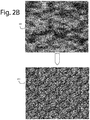
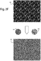
- FIGS. 2B-2H and 2J-2M are detailed views of the various patterns included in FIG. 2A ;
- FIGS. 2N and 2P are four-times and twenty-six times magnifications of small portions of the distorted-grid mesh-texture concealment four-color camouflage pattern in FIG. 2M . These are presented herein to show how the regular placement of consistently sized, but darker-than-average, blobs and splotches of color, in conjunction with the mesh-textured overlay, give the appearance of natural blending at stand-off distances;
- FIG. 3 is a perspective view diagram of a substrate printed on one side with a whole single tile of the repeatable concealment pattern produced by the Method of FIG. 2A , e.g., the pattern of FIG. 2M ;
- FIG. 4 is a perspective view diagram of a flexible blanket-sized Mylar substrate printed on one side with two whole single tiles of the repeatable concealment pattern seamlessly joined together along the dashed line;
- FIG. 5 is a perspective view diagram of a roll of adhesive backed duct tape printed on one side with partial tiles of the repeatable concealment pattern seamlessly joined heel-to-toe along its longitudinal run;
- FIG. 6 is a cartoon diagram representing what a user would see on an LCD monitor screen when camera is imaging a video raster of a natural jungle terrain from a kilometer away;
- FIG. 7 is a diagram representing twenty-four 15° relative visual orientations, 0°-360°, that a message such as COMPANY-B could appear as in the field-of-view of a level camera. If a COMPANY-B message is present, and the PRN used is correct, one of the decoding shift registers of FIG. 1 will produce a message output, “COMPANY-B”.
- FIG. 1 represents a pseudo-random camouflage system 100 in an embodiment of the present invention.
- the pseudo-random camouflage system 100 can factory produce a sheet of pseudo-random camouflage 102 comprising a visible surface of a pseudo-randomly generated and positioned mixed-collection of blobs, splotches, drops, spots, globules, and blotches.
- a second field-deployed part can then optically resolve and read the messages encrypted in a pseudo-random camouflage captured image 104 .
- These images can be obtained in any orientation and at practical distances.
- the sheet of pseudo-random camouflage 102 can be produced in an ink-jet printer, silkscreen process, or other method that can faithfully produce a computed pseudo-random camouflage pattern on any tangible object. One extreme would be light projection on a reflective surface.
- the pseudo-random camouflage need not be limited to sheets of material, but could be applied to any tangible substrate like military armor, vehicles, etc.
- blobs, splotches, drops, spots, globules, and blotches are words in ordinary usage meant herein to describe the variety of ways inks, paints, and other contrasts applied to tangible materials will appear to observers and have no predefined or predictable borders, perimeters, shapes, or shadings.
- a message 110 (e.g., COMPANY-B) and surrounding pattern fill 112 are applied to a code division multiplex access (CDMA) modulator 114 that uses a PRN code 116 to produce what appears to be digital noise 118 .
- CDMA code division multiplex access
- a raster generator 120 places the message 110 and pattern fill 112 into a two-dimensional (2D) image raster representing the size of the tangible object to be printed or otherwise painted like sheet 102 . Multiple image rasters can be tiled onto the tangible object to make the application more practical.
- An ink-jet printer 122 is an example of a device that can permanently apply the image raster to a sheet substrate.
- a palette of camo-colors 124 are selected to produce the best concealment given a selected use environment, e.g., jungle, desert, sky, sea, etc.
- Sheets of pseudo-random camouflage 102 are stockpiled, warehoused, transported, distributed and otherwise deployed to the field for use.
- a printable and displayable message 110 is chosen according to how and where the particular pseudo-random steganographic camouflage on the substrate is intended to be deployed.
- the printable and displayable message 110 is typically able to identify people, equipment, assets, hazards, and installations concealable by the pseudo-random steganographic camouflage printed on the substrate. It can also be used to hide or secret a trademark, copyright notice, security or counterfeiting countermeasure, etc.
- a fill pattern 112 is needed to visibly submerge the message 110 when it's printed or displayed.
- the particular camouflage theme for the fill pattern includes conventional desert, jungle, woodland, sky, and sea palettes of colors and patterns.
- a pseudo-random number (PRN) set 116 is needed for encoding a code in a code-division multiple access (CDMA) modulator 114 .
- the modulator 114 controls a digital serialization 118 of the message 110 and the fill pattern 112 with the PRN 116 into component colors, saturations, and light levels adhering to a particular camouflage theme, e.g., camo colors 124 .
- a two-dimensional raster generator 120 converts a serialization of the message and the fill pattern with the PRN code into a raster of horizontal scanning lines for color printing.
- a color printer, silkscreen, paint sprayer or other similar device applies paints, inks, and other colored materials to a substrate according to the serialization of the message and the fill pattern with the PRN into component colors, saturations, and light levels.
- the challenge here is not unlike a global positioning system (GPS) navigation receiver which must first replicate the PRN code that is transmitted by the satellite vehicle (SV) being acquired by the receiver; then it must shift the phase of the replica code until it correlates with the SV PRN code.
- GPS global positioning system
- the same correlation properties occur that occurs for the mathematical autocorrelation process for a given PRN code.
- Receiver correlation processes are very different from autocorrelation processes because only selected points of the correlation envelope are found and examined by the receiver.
- the phase of the GPS receiver replica code matches the phase of the incoming SV code, there is maximum correlation.
- GPS receivers When the phase of the replica code is offset by more than one “chip” (serial bit) on either side of the incoming SV code, there is minimum correlation. This is how GPS receivers detect the SV signals when acquiring or tracking the SV signals in the code phase dimension. GPS receivers must also detect the SV in the carrier phase dimension by replicating the carrier frequency to obtain carrier phase lock with the SV signal. So, GPS signal acquisition and tracking process is a two-dimensional, code and carrier, signal replication process. See, Ward, Betz, and Hegarty, Satellite Signal Acquisition, Tracking, and Data Demodulation . UNDERSTANDING GPS PRINCIPLES AND APPLICATIONS 2nd Ed., ISBN 1580538940, ⁇ 2006.
- carrier phase is not an uncertainty, but the relative visual orientation of a camera to the lay of image 104 deployed in the field is uncertain.
- the uncertainty as to range and zoom can be mitigated by measuring the range, e.g., with LIDAR.
- the PRN code 116 will repeat many times in each raster. How the chips shift and wiggle represents the modulation data of the message 110 .
- the message 110 is visually submerged into pseudo-random steganographic camouflage 102 and is discernable from the fill 112 and readable as to the content to only cameras equipped with a CDMA demodulator and a correct PRN.
- Typical substrates include tangible sheet and bulk materials that can receive and retain inks, paints, and decorations on their surfaces from the printer.
- the raster generator 120 sends a serial stream of digital data to the printer 122 as a series of progressive scan lines that are recoverable by a digital camera employing raster scanning and a matching serial output.
- the second, field deployable part of pseudo-random camouflage system 100 has a camera 130 that is positioned and focused such that it can capture PRN-camo image 104 .
- a light detection and ranging (LIDAR) device 132 measures the distance and obtains a range. This is important to ascertain the degree of zoom necessary for camera 130 to produce a raster of a digital image that can be read for the message 110 .
- LIDAR light detection and ranging
- camera 130 could be mounted coaxially on an axle to rotate with a step motor in one degree increments, searching for the correct relative orientation. That is if time permits.
- a filtered digital image 136 produced by an image processor represents PRN-camo image 104 in the relative orientation that camera 130 finds itself at the moment in the field.
- the PRN-camo image 104 could have the message 110 upside down or sideways, and thus frustrate simple PRN code searches and CDMA demodulation.
- CDMA demodulators 140 A- 140 D are intended to represent however many serial shift registers are necessary. Each is fed with a trial phasing of PRN 116 by a phase generator 142 . If the PRN phase gets lucky, and if message 110 is present in PRN-camo image 104 , one of the CDMA demodulators 140 A- 140 D will spit out a valid character string. The others will produce noise.
- the valid character string is easy enough to present in a user display in a visual display position and orientation derived from its processing.
- Serialized and rasterized digital image streams here are not unlike what a GPS receiver would sense from a GPS satellite that transmits CDMA messages encoded with the satellite almanac and system time.
- CDMA demodulation based on a fixed known set of PRNs is conventional and highly developed in the navigation satellite receiver art. For example, see Satellite Signal Acquisition, Tracking, and Data Demodulation , by Phillip W. Ward NAVWARD GPS Consulting, and John W. Betz and Christopher J. Hegarty, The MITRE Corporation, pp.
- FIGS. 2A-2M represent a graphics design method 200 in an embodiment of the present invention for rendering, e.g., a concealment pattern that is printed or painted on substrates like Mylar blankets and adhesive waterproof tapes in rolls.
- a first set of patterns 201 - 204 are generated from a mix mix of pseudo-random monochrome noise using a graphics design software like Adobe Illustrator.
- the pseudo-random part is a code division multiplex access (CDMA) modulation of a “Message”. E.g., COMPANY-B.
- CDMA code division multiplex access
- a drab green color 231 is shifted by contrast level 221 between a darker-than-average drab green color 232 and a lighter-than-average drab green color 233 .
- a grey color 234 is filtered by contrast level 222 to turn on or off grey color 235 .
- a tan color 237 is shifted by contrast level 223 between a darker-than-average tan color 238 and a lighter-than-average tan color 239 .
- a brown color 240 is filtered by contrast level 224 to turn on or off brown color 241 .
- Patterns 201 and 211 can be seen in much finer detail in FIG. 2B .
- Patterns 202 and 212 can be seen in much finer detail in FIG. 2C .
- Patterns 203 and 213 can be seen in much finer detail in FIG. 2D .
- Patterns 204 and 214 can be seen in much finer detail in FIG. 2E .
- Resulting pattern 231 that shifts between drab green colors 232 and 233 according to pattern 221 is presented in much finer detail in FIG. 2F .
- Color 234 that is filtered by pattern 222 is presented in much finer detail in FIG. 2G .
- Resulting pattern 237 that shifts between tan colors 238 and 239 according to pattern 223 is presented in much finer detail in FIG. 2H .
- Color 240 that is filtered by pattern 224 is presented in much finer detail in FIG. 2J .
- a first color pattern group 250 results from adding together 221 , 231 , 222 , and 234 .
- a monochrome mixing map 251 is added with a second color pattern group 252 that is the sum of 223 , 237 , 224 , and 240 . See FIG. 2K .
- the three added together form a final four-color camouflage pattern 253 . See FIG. 2L . Such can be the final step in this process, and printed on a substrate.
- a distorted-grid mesh-texture pattern 254 is added to four-color camouflage pattern 253 to further distort the repeatable patterns, as well as provide an appearance of mesh-textured for printing on some Mylar blankets, duct tape, and other products. See FIG. 2L for finer details of the patterns. Such mesh-textured is an option.
- a distorted-grid mesh-texture concealment four-color camouflage pattern 260 is the final product of these steps and can be seen in finer detail in FIG. 2M .
- the graphic design is repeated in 230-cm ⁇ 205-cm rectangular virtual tiles that visually blend seamlessly with identical neighbor tiles top-bottom and left-right sides.
- the graphic design includes two main elements throughout, a mesh-texture using fine grid shadowing and a color of woodland color splotches and blobs that mimic natural, unoccupied woodland settings and scenery.
- a further refinement visually adds a distorted-grid mesh-texture to the concealment camouflage, and even faint “watermarks” of commercial trademarks plain to see or encrypted signatures and messages hidden in plain sight.
- FIGS. 2N and 2P are four-times and twenty-six times magnifications of small portions of the distorted-grid mesh-textured concealment four-color camouflage pattern 260 in FIG. 2M . These show how the regular placement of consistently sized, but darker-than-average, blobs and splotches of color give the appearance of mesh-textured at stand-off distances.
- Method 200 is one way of making a concealment substrate embodiment of the present invention.
- a first step generates a monochrome raster ( 201 - 204 ) of random noise for each of four colors ( 232 , 235 , 238 , and 241 ) in a camouflage color palette.
- a next step rotates and equally tiles each of the four random-noise monochrome rasters as four individual tiles ( 211 - 214 ).
- a further step adds to each of the four random-noise monochrome rasters ( 211 - 214 ) a corresponding two-tone contrast level ( 221 - 224 ) to the four individual tiles.
- a next step adds to each of the four random-noise monochrome rasters a corresponding green, grey, tan, and brown color according to its respective two-tone contrast level.
- a next step mixes together a pair of color pattern groups ( 250 , 252 ) of the above according to a monochrome mixing map ( 251 ) to obtain a unique camouflage pattern ( 253 ).
- a further step prints a substrate ( 201 , 302 ) with whole and partial tiles ( 304 , 306 ) of the unique camouflage pattern repeated as necessary to join seamlessly along each edge ( 308 ) with a neighboring tile.
- an optional step adds to the unique camouflage pattern ( 253 ) a visual mesh-textured raster ( 254 ), followed by printing of the combination ( 260 ).
- Other embodiments comprise graphics depicting the visual mesh-texture.
- a first plurality of overlapping and unsystematically positioned blobs, splotches, drops, spots, globules, and blotches are such that each constituent comprises a unique proportioned combination within any one rectangular shaped tile area of, e.g., cyan-magenta-yellow-black (CMYK) color pigments in a limited range of cyan, a limited range of magenta, a limited range of yellow, and a limited range of black.
- CMYK cyan-magenta-yellow-black
- Others can use RGB or Pantone instead of CMYK.
- each constituent comprises a unique shape within any one rectangular shaped tile area, and each constituent has an area size in the range of 2% to 20% of the area size of any one whole rectangular shaped tile area.
- FIG. 3 represents a woodlands concealment product 300 with a base substrate 301 printed on one side with a whole single tile of the repeatable concealment pattern 202 produced by the Method of FIG. 2A , e.g., the pattern of FIG. 2M .
- Commercial materials that can be used for the base substrate 301 include paper, vinyl, tarps, spread cloths, foils, and stickers.
- FIG. 4 represents a woodlands concealment emergency blanket 400 of a flexible blanket-sized Mylar substrate 302 printed on one side with two whole single tiles 404 and 406 of the repeatable concealment pattern 260 ( FIG. 2M ) seamlessly joined together along the dashed line 408 .
- a typical tile will be 230-cm by 205-cm.
- a typical heat-reflective emergency survival blanket will be 52′′ by 84′′ (232-cm by 214-cm).
- a similar flexible blanket-sized Mylar substrate 302 was developed by NASA in 1964 for the US space program. That material was a thin sheet of polyethylene terephthalate (PET) plastic, and deposition coated with a metallized reflector, usually gold or silver in color, and that reflects up to 97% of radiated heat.
- PET polyethylene terephthalate
- polyimide substrate e.g., KAPTON, UPILEX®
- KAPTON UPILEX®
- Aluminized kapton with foil thickness of 50 and 225 ⁇ m, was used on the Apollo Lunar Module.
- the polyimide gives the foils their distinctive amber-gold color.
- Space blankets are made by vaporizing pure aluminum and vacuum depositing micron thick films onto very thin, durable plastic substrates.
- FIG. 5 is a perspective view diagram of a roll of waterproof-adhesive backed duct tape 500 printed on an outer side 502 with partial tiles of the repeatable concealment pattern 260 ( FIG. 2M ). Such tiles are seamlessly joined heel-to-toe along its longitudinal run.
- the inner side 504 has a waterproof adhesive and the tape material itself is a fabric. For example, a polyethylene-coated textile fabric cut into linear strips and coiled onto rolls 506 .
- the tape 500 can be used to join together blankets 300 without disrupting the camouflage benefits.
- the “printing” of pattern 260 ( FIG. 2M ) onto a base substrate includes conventional ink stamping, ink rolling, ink jet, silk screening, digital printing, laser xerography printing, spray painting, and other color pigment transfer and dye technologies.
- the unique camouflage pattern 260 ( FIG. 2M ) can have at multiple variants, e.g., what we will trademark as HUNTER'S SHROWD, and WOODLAND SHROWD, which is the same design but uses a greener color pallet for the woodland shroud variant. Such designs are mostly aesthetic, as its usefulness has not been proven in the field yet. Since this particular pattern has never been seen before, it is still aesthetically pleasing, and it creates a value in the eyes of buyers.
- One objective of the present invention is to create patterns that never have been seen before. These here can't be recreated because the baseline monochrome random noise element produces a different result each time it's executed in the method 200 . An adversary's knowing what to look for when searching for a camouflaged individual befuddles easy discovery.
- Duct tape 500 is similarly improved by unique camouflage pattern 260 ( FIG. 2M ). The many useful properties and functions of standard silver-colored duct tape are maintained, while not creating obvious unnatural reflective delineations on the material it is used on. In addition, duct tape 400 can be used to cover monotone color painted equipment such as weapons and battle helmets in situations where better concealment is preferred.
- the top half of FIG. 1 represents a factory portion of a pseudo-random camouflage system 100 that can produce a pseudo-random camouflage on a substrate.
- Such pseudo-random camouflage appears on a visible surface as a pseudo-randomly generated and positioned mixed-collection of blobs, splotches, drops, spots, globules, and blotches.
- the bottom half of FIG. 1 represents a field deployable portion of pseudo-random camouflage system 100 that can, at practical distances, optically resolve and read encrypted messages visually appearing on the surface of a substrate with pseudo-random camouflage in an image captured in any orientation.
- FIG. 6 represents a cartoon 600 of what a user would see on an LCD monitor screen when camera 130 is imaging a video raster of a natural jungle terrain from a kilometer away. At least one of our concealment substrates 102 is captured inside this field-of-view and each occupies, for example, ten percent of the raster area. Camera 130 would see these portions patched with PRN-camo image 104 , and not see what is being concealed. Before any authorized message decoding, the concealment of the camouflage is as effective, as any conventional camouflage for this environment would ordinarily be. The object is our “friendlies” can be revealed to us but not to them because we hold the key, PRN 116 . We can then take steps to assist, and not harm the friendlies, and they can remain passive and quiet because we don't need them to tell us anything.
- Steganography is the practice of concealing a secret message within another, ordinary, message. Commonly, steganography is used to unobtrusively hide a small message within the noisy regions of a larger image.
- a concealment substrate 102 with pseudo-random noise in a natural field-of-view that a camera 130 will image as only a small part 104 .
- Shumeet Baluja created deep neural networks that were simultaneously trained to create hiding and revealing processes and were designed to specifically work as a team.
- the system was trained on images drawn randomly from an ImageNet database, and worked well on natural images from a wide variety of sources. Beyond demonstrating the successful application of deep learning to hiding images, he examines how the result was achieved and explores extensions.
- Popular steganographic methods encode the secret message within the least significant bits of a carrier image, his approach compresses and distributes the secret image's representation across all of the available bits.
- COMPANY-B has concealed themselves under a concealment substrate 102 that was generated with PRN 116 .
- a message, “COMPANY-B” was modulated into the camouflage printing.
- Camera 130 is not naturally squared with the message in the field, in fact, the relative orientations are never known to begin with. So all orientations 0°-360° must be expected as possible and every one tried. Best if all tries are accomplished in parallel. But one at a time is practical and could be attempted by mechanically rotating camera 130 .
- FIG. 1 we chose to electronically resolve the orientations to 15° sets of twenty-four.
- CDMA demodulators 140 A- 140 D represented all of these. More than twenty-four may be needed, at this point the correct number is unknown due to a lack of test data.
- FIG. 7 represents the twenty-four 15° orientations, 0°-360°, that COMPANY-B could appear as in the field-of-view of camera 130 . If COMPANY-B is present, one of the decoding shift registers will produce a message output, “COMPANY-B”. How it was oriented would be useful to mimic in the user display screen cartoon 600 . A landing zone (LZ) might also have been concealed by and near COMPANY-B.
Landscapes
- Engineering & Computer Science (AREA)
- Multimedia (AREA)
- Signal Processing (AREA)
- General Engineering & Computer Science (AREA)
- Printing Methods (AREA)
- Editing Of Facsimile Originals (AREA)
Abstract
Description
- The present invention relates to concealment-type survivalist gear, and more particularly to a tiled and mesh-textured camouflage-pattern graphic designs with encoded steganographic messages applied to a substrate like plastic films, adhesive tapes, clothing, tents, blankets, vehicles, etc.
- Camouflage can use any combination of materials, coloration, or illumination for concealment, either by making people or equipment hard to discern by sight, or by masquerading as something else more expected. Examples include jungle cover, desert sands, blue sky, grasses and tree litter, soils, leaves, and snow. Gilly suits actually cover a sniper with an overall decorated with fake mosses, twigs, grasses, dirt, leaves, etc. Natural clutter on an optical level to natural vision or cameras will resolve as stills or video rasters of noise. In videos, waves through the noise can appear to be wind in the grasses or trees, waves in the water, and clouds in the skies.
- One object of camouflage is to be able to hide personnel and equipment behind cover from easy visual detection in the field by adversaries or prey. The basic method used is to match the colors and patterns on the camouflage to the immediate surrounds so that at a distance there are no sharp, recognizable silhouettes or outlines. Camouflage effective in contrast to one background or environment may stand out and yell loudly in another. The chameleon has been able to overcome this limitation, but manmade camouflage is not near as adaptable or as good at adapting and blending in.
- Warships and combat aircraft are routinely painted with desert, woodland, artic, blue sky, open sea, and other colors and patterns to help conceal such equipment out in the open. Some warships and combat aircraft will, of course, be “friendlies” and some will be foes. Conventional camouflage conceals both the same. And so a misidentification caused by the concealment can be costly or deadly.
- In 2005 the US Army adopted the Universal Camouflage Pattern as the standard camouflage pattern for all environments. When soldiers started to complain about it completely underperforming in every environment the Army issued a Solicitation for a better pattern.
- “The US Army Contracting Center, Aberdeen Proving Ground (Soldier, Chemical, Research & Test), Natick Contracting Division (NCD) on behalf of the US Army Soldier System Center, Natick, Mass. (Product Manager Soldier Clothing and Individual Equipment), intends to issue a solicitation under Authority of FAR Part 15, for a research and development effort to work with multiple vendors to develop a family of camouflage patterns. The family is comprised of three patterns/color palettes for the uniforms (i.e., wooded, arid and transitional), which have the same or similar geometry, and one pattern for the personal protective equipment (PPE)/organizational clothing and individual equipment (OCIE), which may or may not be one of the uniform patterns. The uniform patterns/palettes must be compatible with the PPE/OCIE pattern/palette. The first objective of this effort is to develop for the US Army a family of camouflage patterns that offers improved concealment and reduced detection capability over current patterns. The second objective is to acquire the data rights for a portion or all of the best performing camouflage pattern families. The Government anticipates that this requirement will be competed full and open; however, the Government reserves the right to change the solicitation procedure. Firms shall not be reimbursed for any costs associated with proposals. The Government envisions multiple awards, to a Business under North American Industry Classification System code 541712, and Federal Supply Code 8731. When released, the solicitation, including all amendments and applicable documents, will be available in electronic substrate, on or about Mar. 18, 2011, at the US Army Contracting Center, Aberdeen Proving Ground (SCRT), Natick Contracting Division website, https://www3.natick.army.mil
- On May 23, 2014, the US Army announced that the Scorpion pattern, a predecessor to Crye Precision's MultiCam, was selected to replace UCP as the Army's standard camouflage pattern, despite the fact that it was dropped from the trials for being too similar to MultiCam.
- Crye Precision's MultiCam pattern also forms a basis for the British MTP pattern then replacing the DPM and the new (2013) AMP (Australian Multicam Pattern) which will replace the DPCU. Polish special forces are using a version of the Multicam called Suez. MultiCam is a single camouflage pattern that helps a wearer hide in varied environments, seasons, elevations, and light conditions. It tries to address a real-world need for concealment in different environments, with one basic kit of gear. While there are many location-specific patterns, MultiCam work across a very broad range of environmental conditions when observed in both the visual and near infrared (night vision) spectrums. The pattern reflects some of the surrounding colors of the environment. It takes on an overall green appearance when under a green forest canopy, and an overall tan look when in the open desert. By adapting to varying local lighting conditions, it blends with many environments, elevations, seasons, weather conditions, and times of the day. The design is based on the way the human eye and brain perceive shapes, volumes, and colors. Only a very small portion of the human eye can perceive color, so the brain does a lot of interpolating. MultiCam uses this principle to help observers “see” the pattern as part of the background. MultiCam relies on a blending effect, rather than a contrast effect to mask the wearer. This effect allows it to perform in a wide range of environments, and keeps the pattern effective even at close distances where pixelated or “blocky” patterns will often stand out against natural, non-blocky environments.
- What would be very useful in the field of camouflage would be camouflage that visually flashed a marker identifying the “friendly” and yet maintained the concealment to foes or unauthorized spotters. Not directly of course, but with “authorized” digital imaging cameras. For example, the Marker could be something that resolved after decryption to “USA”, “Company-B”, “Press”, “FIELD HOSPITAL”, “Battery-C”, “Deer Hunters”, “Tunnel Entrance”, etc.
- Briefly, a concealment substrate embodiment of the present invention comprises a graphic design printed or painted as camouflage on substrates like mesh-textured uniforms, military equipment, Mylar thermal blanket sheets, adhesive tapes, etc. The graphic design is uniquely generated from pseudo-random noise in four overlaying colors that each begin as a raster of randomly generated noise in a standardized tile size. E.g., gray, green, tan, and brown colors natural for concealment applications are each masked by two-tone image contrast rasters. The four results are mixed in groups together with a monochrome mixing mask to produce a whole tile of concealment camouflage that will conjoin seamlessly within arrays of such tiles. A further refinement visually adds a distorted-grid mesh-texture overly texture to the concealment camouflage, and even faint “watermarks” of commercial trademarks.
- These and other objects and advantages of the present invention no doubt become obvious to those of ordinary skill in the art after having read the following detailed description of the preferred embodiments which are illustrated in the various drawing figures.
-
FIG. 1 is a functional block diagram of a pseudo-random camouflage system in an embodiment of the present invention. The pseudo-random camouflage system has a factory to produce a sheet of pseudo-random camouflage comprising a pseudo-randomly generated and positioned collection of blobs, splotches, drops, spots, globules, and blotches. A second field-deployed part can then optically resolve and read encrypted messages in a pseudo-random camouflage captured image obtained in any orientation and practically at any distance; -
FIG. 2A is a flowchart diagram of a graphics design method embodiment of the present invention for rendering a pseudo-random concealment pattern that is printed, painted, or otherwise permanently deposited as color pigments on a substrate; -
FIGS. 2B-2H and 2J-2M are detailed views of the various patterns included inFIG. 2A ; -
FIGS. 2N and 2P are four-times and twenty-six times magnifications of small portions of the distorted-grid mesh-texture concealment four-color camouflage pattern inFIG. 2M . These are presented herein to show how the regular placement of consistently sized, but darker-than-average, blobs and splotches of color, in conjunction with the mesh-textured overlay, give the appearance of natural blending at stand-off distances; -
FIG. 3 is a perspective view diagram of a substrate printed on one side with a whole single tile of the repeatable concealment pattern produced by the Method ofFIG. 2A , e.g., the pattern ofFIG. 2M ; -
FIG. 4 is a perspective view diagram of a flexible blanket-sized Mylar substrate printed on one side with two whole single tiles of the repeatable concealment pattern seamlessly joined together along the dashed line; -
FIG. 5 is a perspective view diagram of a roll of adhesive backed duct tape printed on one side with partial tiles of the repeatable concealment pattern seamlessly joined heel-to-toe along its longitudinal run; -
FIG. 6 is a cartoon diagram representing what a user would see on an LCD monitor screen when camera is imaging a video raster of a natural jungle terrain from a kilometer away; and -
FIG. 7 is a diagram representing twenty-four 15° relative visual orientations, 0°-360°, that a message such as COMPANY-B could appear as in the field-of-view of a level camera. If a COMPANY-B message is present, and the PRN used is correct, one of the decoding shift registers ofFIG. 1 will produce a message output, “COMPANY-B”. -
FIG. 1 represents apseudo-random camouflage system 100 in an embodiment of the present invention. Thepseudo-random camouflage system 100 can factory produce a sheet ofpseudo-random camouflage 102 comprising a visible surface of a pseudo-randomly generated and positioned mixed-collection of blobs, splotches, drops, spots, globules, and blotches. - A second field-deployed part can then optically resolve and read the messages encrypted in a pseudo-random camouflage captured
image 104. These images can be obtained in any orientation and at practical distances. The sheet ofpseudo-random camouflage 102 can be produced in an ink-jet printer, silkscreen process, or other method that can faithfully produce a computed pseudo-random camouflage pattern on any tangible object. One extreme would be light projection on a reflective surface. - More generally, the pseudo-random camouflage need not be limited to sheets of material, but could be applied to any tangible substrate like military armor, vehicles, etc.
- Herein, blobs, splotches, drops, spots, globules, and blotches are words in ordinary usage meant herein to describe the variety of ways inks, paints, and other contrasts applied to tangible materials will appear to observers and have no predefined or predictable borders, perimeters, shapes, or shadings.
- As an example of what is meant by a “mixed-collection of blobs, splotches, drops, spots, globules, and blotches”, see How To Create a Repeating Camo Pattern in Illustrator, by Chris Spooner, https://blog.spoongraphics.co.uk/, 29 Nov. 2010.
- A message 110 (e.g., COMPANY-B) and surrounding pattern fill 112 are applied to a code division multiplex access (CDMA)
modulator 114 that uses aPRN code 116 to produce what appears to be digital noise 118. Araster generator 120 places themessage 110 and pattern fill 112 into a two-dimensional (2D) image raster representing the size of the tangible object to be printed or otherwise painted likesheet 102. Multiple image rasters can be tiled onto the tangible object to make the application more practical. An ink-jet printer 122 is an example of a device that can permanently apply the image raster to a sheet substrate. A palette of camo-colors 124 are selected to produce the best concealment given a selected use environment, e.g., jungle, desert, sky, sea, etc. - Sheets of
pseudo-random camouflage 102 are stockpiled, warehoused, transported, distributed and otherwise deployed to the field for use. - Once in the field, individual sheets of
pseudo-random camouflage 102 are used to cover, blanket, or other conceal people, equipment, and installations from view of detection by adversaries and otherwise unauthorized spotters. But, command and other authorized actors will be enabled to “see” exactly where in the field the people, equipment, and installations hidden from view are exactly positioned. That is, ifPRN 116 is known to them. Otherwise, the individual sheets ofpseudo-random camouflage 102 will operate as conventional camouflage. - A printable and
displayable message 110 is chosen according to how and where the particular pseudo-random steganographic camouflage on the substrate is intended to be deployed. The printable anddisplayable message 110 is typically able to identify people, equipment, assets, hazards, and installations concealable by the pseudo-random steganographic camouflage printed on the substrate. It can also be used to hide or secret a trademark, copyright notice, security or counterfeiting countermeasure, etc. - A
fill pattern 112 is needed to visibly submerge themessage 110 when it's printed or displayed. The particular camouflage theme for the fill pattern includes conventional desert, jungle, woodland, sky, and sea palettes of colors and patterns. - A pseudo-random number (PRN) set 116 is needed for encoding a code in a code-division multiple access (CDMA)
modulator 114. Themodulator 114 controls a digital serialization 118 of themessage 110 and thefill pattern 112 with thePRN 116 into component colors, saturations, and light levels adhering to a particular camouflage theme, e.g., camo colors 124. A two-dimensional raster generator 120 converts a serialization of the message and the fill pattern with the PRN code into a raster of horizontal scanning lines for color printing. A color printer, silkscreen, paint sprayer or other similar device (all represented by ink jet printer 122) applies paints, inks, and other colored materials to a substrate according to the serialization of the message and the fill pattern with the PRN into component colors, saturations, and light levels. - The challenge here is not unlike a global positioning system (GPS) navigation receiver which must first replicate the PRN code that is transmitted by the satellite vehicle (SV) being acquired by the receiver; then it must shift the phase of the replica code until it correlates with the SV PRN code. When cross-correlating the transmitted PRN code with a replica code, the same correlation properties occur that occurs for the mathematical autocorrelation process for a given PRN code. Receiver correlation processes are very different from autocorrelation processes because only selected points of the correlation envelope are found and examined by the receiver. When the phase of the GPS receiver replica code matches the phase of the incoming SV code, there is maximum correlation. When the phase of the replica code is offset by more than one “chip” (serial bit) on either side of the incoming SV code, there is minimum correlation. This is how GPS receivers detect the SV signals when acquiring or tracking the SV signals in the code phase dimension. GPS receivers must also detect the SV in the carrier phase dimension by replicating the carrier frequency to obtain carrier phase lock with the SV signal. So, GPS signal acquisition and tracking process is a two-dimensional, code and carrier, signal replication process. See, Ward, Betz, and Hegarty, Satellite Signal Acquisition, Tracking, and Data Demodulation. UNDERSTANDING GPS PRINCIPLES AND APPLICATIONS 2nd Ed., ISBN 1580538940,© 2006.
- Here, “carrier phase” is not an uncertainty, but the relative visual orientation of a camera to the lay of
image 104 deployed in the field is uncertain. The uncertainty as to range and zoom can be mitigated by measuring the range, e.g., with LIDAR. - The
PRN code 116 will repeat many times in each raster. How the chips shift and wiggle represents the modulation data of themessage 110. - The
message 110 is visually submerged into pseudo-randomsteganographic camouflage 102 and is discernable from thefill 112 and readable as to the content to only cameras equipped with a CDMA demodulator and a correct PRN. Typical substrates include tangible sheet and bulk materials that can receive and retain inks, paints, and decorations on their surfaces from the printer. Theraster generator 120 sends a serial stream of digital data to theprinter 122 as a series of progressive scan lines that are recoverable by a digital camera employing raster scanning and a matching serial output. - The second, field deployable part of
pseudo-random camouflage system 100 has acamera 130 that is positioned and focused such that it can capture PRN-camo image 104. A light detection and ranging (LIDAR)device 132 measures the distance and obtains a range. This is important to ascertain the degree of zoom necessary forcamera 130 to produce a raster of a digital image that can be read for themessage 110. - Alternatively,
camera 130 could be mounted coaxially on an axle to rotate with a step motor in one degree increments, searching for the correct relative orientation. That is if time permits. - A filtered
digital image 136 produced by an image processor represents PRN-camo image 104 in the relative orientation thatcamera 130 finds itself at the moment in the field. The PRN-camo image 104 could have themessage 110 upside down or sideways, and thus frustrate simple PRN code searches and CDMA demodulation. - So in a
splitter 138, twenty-four 15° twists ofdigital image 136 are distributed in parallel to twenty-four serial shift registers that can each independently match toPRN 116. Unauthorized field units will not havePRN 116. If, it turns out empirically, that 15° twists ofdigital image 136 are too large to reliably decodemessage 116, then finer twists and more PRN serial shift decoders will be necessary. This example is merely intended to describe the basic technique. -
CDMA demodulators 140A-140D are intended to represent however many serial shift registers are necessary. Each is fed with a trial phasing ofPRN 116 by aphase generator 142. If the PRN phase gets lucky, and ifmessage 110 is present in PRN-camo image 104, one of the CDMA demodulators 140A-140D will spit out a valid character string. The others will produce noise. - The valid character string is easy enough to present in a user display in a visual display position and orientation derived from its processing.
- Serialized and rasterized digital image streams here are not unlike what a GPS receiver would sense from a GPS satellite that transmits CDMA messages encoded with the satellite almanac and system time. CDMA demodulation based on a fixed known set of PRNs is conventional and highly developed in the navigation satellite receiver art. For example, see Satellite Signal Acquisition, Tracking, and Data Demodulation, by Phillip W. Ward NAVWARD GPS Consulting, and John W. Betz and Christopher J. Hegarty, The MITRE Corporation, pp. 153-241, UNDERSTANDING GPS PRINCIPLES AND APPLICATIONS 2nd Ed., ISBN 1580538940, © 2006, https://pdfs.semanticscholar.org/9897/aecb6eb1d23430480cb915df769 cd93dfd9a.pdf
-
FIGS. 2A-2M represent agraphics design method 200 in an embodiment of the present invention for rendering, e.g., a concealment pattern that is printed or painted on substrates like Mylar blankets and adhesive waterproof tapes in rolls. A first set of patterns 201-204 are generated from a mix mix of pseudo-random monochrome noise using a graphics design software like Adobe Illustrator. The pseudo-random part is a code division multiplex access (CDMA) modulation of a “Message”. E.g., COMPANY-B. - These are individually rotated and tiled to produce a next set of patterns 211-214. Individual two-tone image contrast levels 221-224 are used to fix color transitions in each of the four pattern sets. A drab
green color 231 is shifted bycontrast level 221 between a darker-than-average drabgreen color 232 and a lighter-than-average drabgreen color 233. Agrey color 234 is filtered bycontrast level 222 to turn on or offgrey color 235. Atan color 237 is shifted bycontrast level 223 between a darker-than-averagetan color 238 and a lighter-than-averagetan color 239. Abrown color 240 is filtered bycontrast level 224 to turn on or offbrown color 241. -
Patterns FIG. 2B .Patterns FIG. 2C .Patterns FIG. 2D .Patterns FIG. 2E . Resultingpattern 231 that shifts between drabgreen colors pattern 221 is presented in much finer detail inFIG. 2F .Color 234 that is filtered bypattern 222 is presented in much finer detail inFIG. 2G . Resultingpattern 237 that shifts betweentan colors pattern 223 is presented in much finer detail inFIG. 2H .Color 240 that is filtered bypattern 224 is presented in much finer detail inFIG. 2J . - A first
color pattern group 250 results from adding together 221, 231, 222, and 234. Amonochrome mixing map 251 is added with a secondcolor pattern group 252 that is the sum of 223, 237, 224, and 240. SeeFIG. 2K . The three added together form a final four-color camouflage pattern 253. SeeFIG. 2L . Such can be the final step in this process, and printed on a substrate. - A distorted-grid mesh-
texture pattern 254 is added to four-color camouflage pattern 253 to further distort the repeatable patterns, as well as provide an appearance of mesh-textured for printing on some Mylar blankets, duct tape, and other products. SeeFIG. 2L for finer details of the patterns. Such mesh-textured is an option. A distorted-grid mesh-texture concealment four-color camouflage pattern 260 is the final product of these steps and can be seen in finer detail inFIG. 2M . - In one embodiment of the invention, the graphic design is repeated in 230-cm×205-cm rectangular virtual tiles that visually blend seamlessly with identical neighbor tiles top-bottom and left-right sides. The graphic design includes two main elements throughout, a mesh-texture using fine grid shadowing and a color of woodland color splotches and blobs that mimic natural, unoccupied woodland settings and scenery.
- A further refinement visually adds a distorted-grid mesh-texture to the concealment camouflage, and even faint “watermarks” of commercial trademarks plain to see or encrypted signatures and messages hidden in plain sight.
- As a consequence of
method 200, and for one forest concealment embodiment only, all the colors used cluster around shades of gray, green, brown, and drab green, olive drab, and army green, no two blobs seem to have exactly the same Cyan-Magenta-Yellow-Black (CMYK) color values. And so it could be said thousands of color shades are being used. And, because of the random noise generated rasters, no two blobs seem to have the same exact shapes, as all appear unique. - There are, however, general consistencies in blob sizes, about a dozen blob size groups. The mesh-texturing occurs parallel wave lines and each virtual intersecting thread occurs at regular period longitudinal and lateral positions represented by consistently sized blobs that are a few shades darker-than-average than the larger blobs that they overlay.
-
FIGS. 2N and 2P are four-times and twenty-six times magnifications of small portions of the distorted-grid mesh-textured concealment four-color camouflage pattern 260 inFIG. 2M . These show how the regular placement of consistently sized, but darker-than-average, blobs and splotches of color give the appearance of mesh-textured at stand-off distances. -
Method 200 is one way of making a concealment substrate embodiment of the present invention. A first step generates a monochrome raster (201-204) of random noise for each of four colors (232, 235, 238, and 241) in a camouflage color palette. A next step rotates and equally tiles each of the four random-noise monochrome rasters as four individual tiles (211-214). A further step adds to each of the four random-noise monochrome rasters (211-214) a corresponding two-tone contrast level (221-224) to the four individual tiles. A next step adds to each of the four random-noise monochrome rasters a corresponding green, grey, tan, and brown color according to its respective two-tone contrast level. A next step mixes together a pair of color pattern groups (250, 252) of the above according to a monochrome mixing map (251) to obtain a unique camouflage pattern (253). A further step prints a substrate (201, 302) with whole and partial tiles (304, 306) of the unique camouflage pattern repeated as necessary to join seamlessly along each edge (308) with a neighboring tile. - In one embodiment, an optional step adds to the unique camouflage pattern (253) a visual mesh-textured raster (254), followed by printing of the combination (260). Other embodiments comprise graphics depicting the visual mesh-texture.
- A first plurality of overlapping and unsystematically positioned blobs, splotches, drops, spots, globules, and blotches are such that each constituent comprises a unique proportioned combination within any one rectangular shaped tile area of, e.g., cyan-magenta-yellow-black (CMYK) color pigments in a limited range of cyan, a limited range of magenta, a limited range of yellow, and a limited range of black. Others can use RGB or Pantone instead of CMYK. These overlapping and unsystematically positioned blobs, splotches, drops, spots, globules, and blotches are such that each constituent comprises a unique shape within any one rectangular shaped tile area, and each constituent has an area size in the range of 2% to 20% of the area size of any one whole rectangular shaped tile area.
-
FIG. 3 represents awoodlands concealment product 300 with abase substrate 301 printed on one side with a whole single tile of therepeatable concealment pattern 202 produced by the Method ofFIG. 2A , e.g., the pattern ofFIG. 2M . Commercial materials that can be used for thebase substrate 301 include paper, vinyl, tarps, spread cloths, foils, and stickers. - The foregoing example is not intended to be limiting nor exclude desert, artic, and other color pallets.
-
FIG. 4 represents a woodlandsconcealment emergency blanket 400 of a flexible blanket-sized Mylar substrate 302 printed on one side with two wholesingle tiles FIG. 2M ) seamlessly joined together along the dashedline 408. Of course however many whole or partial tiles can be seamlessly assembled as tiles to suit whatever product size is commercially necessary. A typical tile will be 230-cm by 205-cm. A typical heat-reflective emergency survival blanket will be 52″ by 84″ (232-cm by 214-cm). - A similar flexible blanket-
sized Mylar substrate 302 was developed by NASA in 1964 for the US space program. That material was a thin sheet of polyethylene terephthalate (PET) plastic, and deposition coated with a metallized reflector, usually gold or silver in color, and that reflects up to 97% of radiated heat. - For use in space, polyimide substrate, e.g., KAPTON, UPILEX®, is preferred due to its resistance to the hostile space environment, large temperature range (cryogenic to −260° C. and for short excursions up to over 480° C.), low outgassing (making it suitable for vacuum use) and resistance to ultraviolet radiation. Aluminized kapton, with foil thickness of 50 and 225 μm, was used on the Apollo Lunar Module. The polyimide gives the foils their distinctive amber-gold color. Space blankets are made by vaporizing pure aluminum and vacuum depositing micron thick films onto very thin, durable plastic substrates.
-
FIG. 5 is a perspective view diagram of a roll of waterproof-adhesive backedduct tape 500 printed on anouter side 502 with partial tiles of the repeatable concealment pattern 260 (FIG. 2M ). Such tiles are seamlessly joined heel-to-toe along its longitudinal run. Theinner side 504 has a waterproof adhesive and the tape material itself is a fabric. For example, a polyethylene-coated textile fabric cut into linear strips and coiled ontorolls 506. Thetape 500 can be used to join togetherblankets 300 without disrupting the camouflage benefits. - The “printing” of pattern 260 (
FIG. 2M ) onto a base substrate includes conventional ink stamping, ink rolling, ink jet, silk screening, digital printing, laser xerography printing, spray painting, and other color pigment transfer and dye technologies. - The unique camouflage pattern 260 (
FIG. 2M ) can have at multiple variants, e.g., what we will trademark as HUNTER'S SHROWD, and WOODLAND SHROWD, which is the same design but uses a greener color pallet for the woodland shroud variant. Such designs are mostly aesthetic, as its usefulness has not been proven in the field yet. Since this particular pattern has never been seen before, it is still aesthetically pleasing, and it creates a value in the eyes of buyers. One objective of the present invention is to create patterns that never have been seen before. These here can't be recreated because the baseline monochrome random noise element produces a different result each time it's executed in themethod 200. An adversary's knowing what to look for when searching for a camouflaged individual befuddles easy discovery. -
Duct tape 500 is similarly improved by unique camouflage pattern 260 (FIG. 2M ). The many useful properties and functions of standard silver-colored duct tape are maintained, while not creating obvious unnatural reflective delineations on the material it is used on. In addition,duct tape 400 can be used to cover monotone color painted equipment such as weapons and battle helmets in situations where better concealment is preferred. - The top half of
FIG. 1 represents a factory portion of apseudo-random camouflage system 100 that can produce a pseudo-random camouflage on a substrate. Such pseudo-random camouflage appears on a visible surface as a pseudo-randomly generated and positioned mixed-collection of blobs, splotches, drops, spots, globules, and blotches. - The bottom half of
FIG. 1 represents a field deployable portion ofpseudo-random camouflage system 100 that can, at practical distances, optically resolve and read encrypted messages visually appearing on the surface of a substrate with pseudo-random camouflage in an image captured in any orientation. -
FIG. 6 represents acartoon 600 of what a user would see on an LCD monitor screen whencamera 130 is imaging a video raster of a natural jungle terrain from a kilometer away. At least one of ourconcealment substrates 102 is captured inside this field-of-view and each occupies, for example, ten percent of the raster area.Camera 130 would see these portions patched with PRN-camo image 104, and not see what is being concealed. Before any authorized message decoding, the concealment of the camouflage is as effective, as any conventional camouflage for this environment would ordinarily be. The object is our “friendlies” can be revealed to us but not to them because we hold the key,PRN 116. We can then take steps to assist, and not harm the friendlies, and they can remain passive and quiet because we don't need them to tell us anything. - In essence, it's a form of Steganography. See, Hiding Images in Plain Sight: Deep Steganography, by Shumeet Baluja Google Research Google, Inc. shumeet@google.com. Steganography is the practice of concealing a secret message within another, ordinary, message. Commonly, steganography is used to unobtrusively hide a small message within the noisy regions of a larger image. We are putting a
concealment substrate 102 with pseudo-random noise in a natural field-of-view that acamera 130 will image as only asmall part 104. Shumeet Baluja created deep neural networks that were simultaneously trained to create hiding and revealing processes and were designed to specifically work as a team. The system was trained on images drawn randomly from an ImageNet database, and worked well on natural images from a wide variety of sources. Beyond demonstrating the successful application of deep learning to hiding images, he examines how the result was achieved and explores extensions. Popular steganographic methods encode the secret message within the least significant bits of a carrier image, his approach compresses and distributes the secret image's representation across all of the available bits. - But COMPANY-B has concealed themselves under a
concealment substrate 102 that was generated withPRN 116. A message, “COMPANY-B” was modulated into the camouflage printing.Camera 130 is not naturally squared with the message in the field, in fact, the relative orientations are never known to begin with. So allorientations 0°-360° must be expected as possible and every one tried. Best if all tries are accomplished in parallel. But one at a time is practical and could be attempted by mechanically rotatingcamera 130. InFIG. 1 we chose to electronically resolve the orientations to 15° sets of twenty-four.CDMA demodulators 140A-140D represented all of these. More than twenty-four may be needed, at this point the correct number is unknown due to a lack of test data. - In
FIG. 6 we assume a practical distance of about a kilometer, but better can be obtained with advanced optics fitted tocamera 130. The degree of zoom or magnification employed in each instant will determine the clock rates needed in the decoding shift registers to yield message outputs. -
FIG. 7 represents the twenty-four 15° orientations, 0°-360°, that COMPANY-B could appear as in the field-of-view ofcamera 130. If COMPANY-B is present, one of the decoding shift registers will produce a message output, “COMPANY-B”. How it was oriented would be useful to mimic in the userdisplay screen cartoon 600. A landing zone (LZ) might also have been concealed by and near COMPANY-B. - Although the present invention has been described in terms of the presently preferred embodiments, it is to be understood that the disclosure is not to be interpreted as limiting. Various alterations and modifications no doubt become apparent to those skilled in the art after having read the above disclosure. Accordingly, it is intended that the appended claims be interpreted as covering all alterations and modifications as fall within the “true” spirit and scope of the invention.
Claims (10)
Priority Applications (4)
| Application Number | Priority Date | Filing Date | Title |
|---|---|---|---|
| US16/358,645 US20200166312A1 (en) | 2016-02-04 | 2019-03-19 | Pseudo-random steganographic camouflage |
| US16/536,281 US11090966B2 (en) | 2016-02-04 | 2019-08-08 | Method for manufacturing pseudo-random steganographic camouflage |
| US29/736,098 USD909070S1 (en) | 2016-02-04 | 2020-05-27 | Sheet material with camouflage pattern |
| US29/764,758 USD949575S1 (en) | 2016-02-04 | 2020-12-31 | Sheet material with camouflage pattern |
Applications Claiming Priority (3)
| Application Number | Priority Date | Filing Date | Title |
|---|---|---|---|
| US29553844 | 2016-02-04 | ||
| US15/016,231 US20160153750A1 (en) | 2016-02-04 | 2016-02-04 | Woodland concealment products |
| US16/358,645 US20200166312A1 (en) | 2016-02-04 | 2019-03-19 | Pseudo-random steganographic camouflage |
Related Parent Applications (2)
| Application Number | Title | Priority Date | Filing Date |
|---|---|---|---|
| US15/016,231 Continuation-In-Part US20160153750A1 (en) | 2016-02-04 | 2016-02-04 | Woodland concealment products |
| US29553844 Continuation-In-Part | 2016-02-04 | 2016-02-04 |
Related Child Applications (1)
| Application Number | Title | Priority Date | Filing Date |
|---|---|---|---|
| US16/536,281 Division US11090966B2 (en) | 2016-02-04 | 2019-08-08 | Method for manufacturing pseudo-random steganographic camouflage |
Publications (1)
| Publication Number | Publication Date |
|---|---|
| US20200166312A1 true US20200166312A1 (en) | 2020-05-28 |
Family
ID=69945455
Family Applications (4)
| Application Number | Title | Priority Date | Filing Date |
|---|---|---|---|
| US16/358,645 Abandoned US20200166312A1 (en) | 2016-02-04 | 2019-03-19 | Pseudo-random steganographic camouflage |
| US16/536,281 Active US11090966B2 (en) | 2016-02-04 | 2019-08-08 | Method for manufacturing pseudo-random steganographic camouflage |
| US29/736,098 Active USD909070S1 (en) | 2016-02-04 | 2020-05-27 | Sheet material with camouflage pattern |
| US29/764,758 Active USD949575S1 (en) | 2016-02-04 | 2020-12-31 | Sheet material with camouflage pattern |
Family Applications After (3)
| Application Number | Title | Priority Date | Filing Date |
|---|---|---|---|
| US16/536,281 Active US11090966B2 (en) | 2016-02-04 | 2019-08-08 | Method for manufacturing pseudo-random steganographic camouflage |
| US29/736,098 Active USD909070S1 (en) | 2016-02-04 | 2020-05-27 | Sheet material with camouflage pattern |
| US29/764,758 Active USD949575S1 (en) | 2016-02-04 | 2020-12-31 | Sheet material with camouflage pattern |
Country Status (1)
| Country | Link |
|---|---|
| US (4) | US20200166312A1 (en) |
Cited By (1)
| Publication number | Priority date | Publication date | Assignee | Title |
|---|---|---|---|---|
| US12620126B1 (en) * | 2023-08-22 | 2026-05-05 | United States Of America As Represented By The Administrator Of Nasa | Apparatus and method of grid-oriented normalization for analysis of spherical areas from 2-D image |
Families Citing this family (6)
| Publication number | Priority date | Publication date | Assignee | Title |
|---|---|---|---|---|
| USD935186S1 (en) * | 2020-02-27 | 2021-11-09 | Asiri Janakantha Wansooriya Mudiyanselage | Hair dryer brush |
| USD934575S1 (en) * | 2020-06-09 | 2021-11-02 | Taiga Ab | Sheet material |
| USD939199S1 (en) * | 2021-01-29 | 2021-12-28 | O2 Partners, Llc | Shoe insole |
| USD1023594S1 (en) * | 2022-11-02 | 2024-04-23 | Taiga Ab | Fabric |
| USD1059349S1 (en) * | 2022-12-21 | 2025-01-28 | Lenovo (Beijing) Limited | Portable computer |
| JP1750566S (en) * | 2023-01-18 | 2023-08-09 | Electronic computer |
Family Cites Families (44)
| Publication number | Priority date | Publication date | Assignee | Title |
|---|---|---|---|---|
| US1650372A (en) | 1924-11-08 | 1927-11-22 | Conrad B Maurer | Scenery-forming paper |
| US2028948A (en) | 1934-11-07 | 1936-01-28 | Beveridge Marvellum Company | Decorative paper and method of making the same |
| SE397000B (en) | 1973-11-01 | 1977-10-10 | Barracudaverken Ab | MASKING CLOTH OR PLATE AND MANUFACTURED THE SAME |
| USD297596S (en) | 1985-07-12 | 1988-09-13 | Marquart Sr James L | Camouflage toilet tissue |
| USD301804S (en) | 1987-01-13 | 1989-06-27 | New Happenin, Ltd. | Camouflage fabric |
| USD301803S (en) | 1987-01-13 | 1989-06-27 | New Happenin, Ltd. | Camouflage fabric |
| USD301805S (en) | 1987-01-15 | 1989-06-27 | Mcilhinney Marybeth A | Camouflage fabric |
| US5066529A (en) | 1990-09-24 | 1991-11-19 | Minnesota Mining And Manufacturing Company | Camouflage wrapping tape |
| US5281460A (en) | 1990-12-04 | 1994-01-25 | Teledyne Industries, Inc. | Infrared camouflage covering |
| US5271999A (en) | 1992-11-16 | 1993-12-21 | Anchor Continental | Duct tape having a non-depositing adhesive |
| ATE287176T1 (en) * | 1993-11-18 | 2005-01-15 | Digimarc Corp | VIDEO WITH HIDDEN IN-BAND DIGITAL DATA |
| US6061828A (en) * | 1997-03-21 | 2000-05-16 | Josephs; Ira | Camouflage items and camouflage material thereon |
| USD428263S (en) | 1999-09-03 | 2000-07-18 | Matthew Huxley Forrest | Crowd and field scene wallpaper |
| USD466701S1 (en) * | 2000-06-22 | 2002-12-10 | Conceria Montebello S.P.A. | Tanned hide |
| USD491372S1 (en) | 2001-06-19 | 2004-06-15 | The United States Of America As Represented By The Secretary Of The Navy | Camouflage pattern for sheet material and uniforms |
| USD474897S1 (en) | 2002-03-14 | 2003-05-27 | Her Majesty The Queen In Right Of Canada As Represented By The Minister Of National Defence | Camouflage pattern applied to material |
| US20040048026A1 (en) | 2002-09-09 | 2004-03-11 | Shen-Nan Kan | Edge-sticking adhesive tape and method of manufacturing the tape |
| USD487848S1 (en) | 2003-05-22 | 2004-03-30 | Lineweight Llc | Camouflage pattern applied to substrate |
| GB0317363D0 (en) | 2003-07-24 | 2003-08-27 | Omnova Wallcovering Uk Ltd | Camouflage covering |
| USD560915S1 (en) | 2006-10-30 | 2008-02-05 | Lineweight Llc | Substrate with camouflage pattern |
| USD592861S1 (en) | 2006-11-14 | 2009-05-26 | Lineweight Llc | Substrate with camouflage pattern |
| USD615762S1 (en) | 2008-01-11 | 2010-05-18 | Bdu, Llc | Substrate with camouflage pattern |
| US20100251455A1 (en) | 2008-01-15 | 2010-10-07 | Lampe Jeffrey L | Camouflage For Day And Night Use |
| CA129323S (en) * | 2008-07-23 | 2010-02-01 | Brooklin S R L | Camouflage fabric |
| USD640062S1 (en) | 2009-09-02 | 2011-06-21 | Tatiana Nicolayevna Shevtsova | Camouflage fabric |
| WO2011050390A1 (en) * | 2009-10-29 | 2011-05-05 | Oscar Moreno De Ayala | Digital watermarking |
| USD659406S1 (en) | 2010-04-22 | 2012-05-15 | Ministry Of Defence | Textile with camouflage pattern |
| USD657961S1 (en) | 2010-09-07 | 2012-04-24 | Brookwood Companies Incorporated | Substrate with camouflage pattern |
| JP5793865B2 (en) * | 2010-12-28 | 2015-10-14 | 富士通株式会社 | Digital watermark embedding device, digital watermark embedding computer program, digital watermark detection device, and digital watermark detection computer program |
| US9150293B1 (en) | 2011-02-23 | 2015-10-06 | Lee Swerdlin | Ocean survival system |
| USD656743S1 (en) | 2011-06-03 | 2012-04-03 | Gore Enterprise Holdings, Inc. | Substrate with camouflage pattern |
| US20140103123A1 (en) * | 2012-10-16 | 2014-04-17 | J. Andrew McKinney, Jr. | System and Method for Encoding and Using a Digital Camouflage Pattern with a Two-Dimensional Code Linked to an Internet Uniform Resource Locator or Context-Sensitive Coded Message |
| USD761571S1 (en) * | 2014-09-10 | 2016-07-19 | Chi-Liang Chou | Cloth with pattern |
| US9062938B1 (en) | 2014-12-12 | 2015-06-23 | The United States Of America As Represented By The Secretary Of The Army | Camouflage patterns |
| US9074849B1 (en) * | 2014-12-12 | 2015-07-07 | The United States Of America As Represented By The Secretary Of The Army | Camouflage for garment assembly |
| USD923342S1 (en) * | 2014-12-12 | 2021-06-29 | U.S. Government As Represented By The Secretary Of The Army | Sheet material with camouflage pattern |
| JP1545394S (en) * | 2015-09-02 | 2019-03-04 | ||
| US20160153750A1 (en) * | 2016-02-04 | 2016-06-02 | Silver Eagle Homes, Inc | Woodland concealment products |
| USD808664S1 (en) | 2016-05-16 | 2018-01-30 | Ninja Brand Incorporated | Sheet with camouflage pattern |
| USD830705S1 (en) | 2016-10-27 | 2018-10-16 | Nta Enterprise, Inc. | Textile with a camouflage pattern |
| USD884362S1 (en) * | 2018-01-19 | 2020-05-19 | Sekisui Chemical Co., Ltd. | Carbon fiber fabric |
| USD913705S1 (en) * | 2019-02-04 | 2021-03-23 | Hunter Douglas Inc. | Fabric with pattern |
| USD908369S1 (en) * | 2019-04-17 | 2021-01-26 | Grand Textile Co., Ltd. | Fabric |
| USD911721S1 (en) * | 2019-09-05 | 2021-03-02 | Swnr Development, Llc | Textile with camouflage pattern |
-
2019
- 2019-03-19 US US16/358,645 patent/US20200166312A1/en not_active Abandoned
- 2019-08-08 US US16/536,281 patent/US11090966B2/en active Active
-
2020
- 2020-05-27 US US29/736,098 patent/USD909070S1/en active Active
- 2020-12-31 US US29/764,758 patent/USD949575S1/en active Active
Cited By (1)
| Publication number | Priority date | Publication date | Assignee | Title |
|---|---|---|---|---|
| US12620126B1 (en) * | 2023-08-22 | 2026-05-05 | United States Of America As Represented By The Administrator Of Nasa | Apparatus and method of grid-oriented normalization for analysis of spherical areas from 2-D image |
Also Published As
| Publication number | Publication date |
|---|---|
| USD949575S1 (en) | 2022-04-26 |
| USD909070S1 (en) | 2021-02-02 |
| US20200103204A1 (en) | 2020-04-02 |
| US11090966B2 (en) | 2021-08-17 |
Similar Documents
| Publication | Publication Date | Title |
|---|---|---|
| US11090966B2 (en) | Method for manufacturing pseudo-random steganographic camouflage | |
| US11060821B2 (en) | Camouflage patterns, arrangements and methods for making the same | |
| US20160153750A1 (en) | Woodland concealment products | |
| US8340358B2 (en) | Visual camouflage with thermal and radar suppression and methods of making the same | |
| Brown et al. | Adversarial patch | |
| Palandro et al. | Change detection in coral reef communities using Ikonos satellite sensor imagery and historic aerial photographs | |
| WO2003030099A3 (en) | Three-dimensional receiving and displaying process and apparatus with military application | |
| US20100088797A1 (en) | Camouflage pattern applied to a surface | |
| US9342910B2 (en) | Systems, processes, and computer program products for creating geo-location-based visual designs and arrangements originating from geo-location-based imagery | |
| US20120132063A1 (en) | Multi-range camouflage design and method | |
| CA2841504A1 (en) | Camouflage patterns | |
| Tibbs et al. | Noise creates polarization artefacts | |
| Amran | Mapping Seagrass Condition Using Google Earth Imagery. | |
| Kwon et al. | Near-infrared imaging polarimetry of GGD 27: Circular polarization and magnetic field structures | |
| US11300385B2 (en) | Camouflage patterns, arrangements and objects utilizing the same | |
| US20200109921A1 (en) | Camouflage pattern having wave-like lines | |
| US20250244107A1 (en) | Method and film for generating thermal and visual deception using metal image lithophane printing and an alpha compositing method for camouflage, shadow elimination, and background blending | |
| US20150290967A1 (en) | Camouflage Design and Method | |
| Youngblood et al. | The Orion Fingers: Near-IR Spectral Imaging of an Explosive Outflow | |
| Barbosa et al. | A Mid-Infrared View of the High Mass Star Formation Region W51A | |
| Baumbach | Colour and camouflage: design issues in military clothing | |
| Khaustov et al. | Complex function as a template for image fusion | |
| Ravindran et al. | Camouflage technology | |
| Bekers et al. | Shape recognition for ships: World War I naval camouflage under the magnifying glass | |
| KR101966640B1 (en) | Sheet for camouflage |
Legal Events
| Date | Code | Title | Description |
|---|---|---|---|
| AS | Assignment |
Owner name: SILVER EAGLE BRANDS, INC., CALIFORNIA Free format text: ASSIGNMENT OF ASSIGNORS INTEREST;ASSIGNOR:KING, JAROD LEE;REEL/FRAME:049686/0315 Effective date: 20190707 Owner name: SILVER EAGLE BRANDS, INC., CALIFORNIA Free format text: ASSIGNMENT OF ASSIGNORS INTEREST;ASSIGNOR:MAIN, RICHARD BREWSTER;REEL/FRAME:049687/0954 Effective date: 20190707 |
|
| STCB | Information on status: application discontinuation |
Free format text: ABANDONED -- FAILURE TO RESPOND TO AN OFFICE ACTION |
|
| AS | Assignment |
Owner name: JEAGR VENTURES LLC, CALIFORNIA Free format text: ASSIGNMENT OF ASSIGNORS INTEREST;ASSIGNOR:SILVER EAGLE BRANDS, INC.;REEL/FRAME:054750/0382 Effective date: 20201203 |