US20200106295A1 - System and Method for Controlling Uninterruptible Power Supply of Electrical Power Systems - Google Patents
System and Method for Controlling Uninterruptible Power Supply of Electrical Power Systems Download PDFInfo
- Publication number
- US20200106295A1 US20200106295A1 US16/144,409 US201816144409A US2020106295A1 US 20200106295 A1 US20200106295 A1 US 20200106295A1 US 201816144409 A US201816144409 A US 201816144409A US 2020106295 A1 US2020106295 A1 US 2020106295A1
- Authority
- US
- United States
- Prior art keywords
- power
- health check
- rotor
- power supply
- storage element
- Prior art date
- Legal status (The legal status is an assumption and is not a legal conclusion. Google has not performed a legal analysis and makes no representation as to the accuracy of the status listed.)
- Granted
Links
Images


Classifications
-
- H—ELECTRICITY
- H02—GENERATION; CONVERSION OR DISTRIBUTION OF ELECTRIC POWER
- H02J—CIRCUIT ARRANGEMENTS OR SYSTEMS FOR SUPPLYING OR DISTRIBUTING ELECTRIC POWER; SYSTEMS FOR STORING ELECTRIC ENERGY
- H02J11/00—Circuit arrangements for providing service supply to auxiliaries of stations in which electric power is generated, distributed or converted
-
- H—ELECTRICITY
- H02—GENERATION; CONVERSION OR DISTRIBUTION OF ELECTRIC POWER
- H02J—CIRCUIT ARRANGEMENTS OR SYSTEMS FOR SUPPLYING OR DISTRIBUTING ELECTRIC POWER; SYSTEMS FOR STORING ELECTRIC ENERGY
- H02J9/00—Circuit arrangements for emergency or stand-by power supply, e.g. for emergency lighting
- H02J9/04—Circuit arrangements for emergency or stand-by power supply, e.g. for emergency lighting in which the distribution system is disconnected from the normal source and connected to a standby source
- H02J9/06—Circuit arrangements for emergency or stand-by power supply, e.g. for emergency lighting in which the distribution system is disconnected from the normal source and connected to a standby source with automatic change-over, e.g. UPS systems
- H02J9/062—Circuit arrangements for emergency or stand-by power supply, e.g. for emergency lighting in which the distribution system is disconnected from the normal source and connected to a standby source with automatic change-over, e.g. UPS systems for AC powered loads
-
- F—MECHANICAL ENGINEERING; LIGHTING; HEATING; WEAPONS; BLASTING
- F03—MACHINES OR ENGINES FOR LIQUIDS; WIND, SPRING, OR WEIGHT MOTORS; PRODUCING MECHANICAL POWER OR A REACTIVE PROPULSIVE THRUST, NOT OTHERWISE PROVIDED FOR
- F03D—WIND MOTORS
- F03D9/00—Adaptations of wind motors for special use; Combinations of wind motors with apparatus driven thereby; Wind motors specially adapted for installation in particular locations
- F03D9/10—Combinations of wind motors with apparatus storing energy
- F03D9/11—Combinations of wind motors with apparatus storing energy storing electrical energy
-
- F—MECHANICAL ENGINEERING; LIGHTING; HEATING; WEAPONS; BLASTING
- F03—MACHINES OR ENGINES FOR LIQUIDS; WIND, SPRING, OR WEIGHT MOTORS; PRODUCING MECHANICAL POWER OR A REACTIVE PROPULSIVE THRUST, NOT OTHERWISE PROVIDED FOR
- F03D—WIND MOTORS
- F03D9/00—Adaptations of wind motors for special use; Combinations of wind motors with apparatus driven thereby; Wind motors specially adapted for installation in particular locations
- F03D9/20—Wind motors characterised by the driven apparatus
- F03D9/25—Wind motors characterised by the driven apparatus the apparatus being an electrical generator
- F03D9/255—Wind motors characterised by the driven apparatus the apparatus being an electrical generator connected to electrical distribution networks; Arrangements therefor
-
- G—PHYSICS
- G01—MEASURING; TESTING
- G01R—MEASURING ELECTRIC VARIABLES; MEASURING MAGNETIC VARIABLES
- G01R15/00—Details of measuring arrangements of the types provided for in groups G01R17/00 - G01R29/00, G01R33/00 - G01R33/26 or G01R35/00
- G01R15/04—Voltage dividers
-
- G01R31/362—
-
- G—PHYSICS
- G01—MEASURING; TESTING
- G01R—MEASURING ELECTRIC VARIABLES; MEASURING MAGNETIC VARIABLES
- G01R31/00—Arrangements for testing electric properties; Arrangements for locating electric faults; Arrangements for electrical testing characterised by what is being tested not provided for elsewhere
- G01R31/36—Arrangements for testing, measuring or monitoring the electrical condition of accumulators or electric batteries, e.g. capacity or state of charge [SoC]
- G01R31/382—Arrangements for monitoring battery or accumulator variables, e.g. SoC
- G01R31/3835—Arrangements for monitoring battery or accumulator variables, e.g. SoC involving only voltage measurements
-
- G—PHYSICS
- G01—MEASURING; TESTING
- G01R—MEASURING ELECTRIC VARIABLES; MEASURING MAGNETIC VARIABLES
- G01R31/00—Arrangements for testing electric properties; Arrangements for locating electric faults; Arrangements for electrical testing characterised by what is being tested not provided for elsewhere
- G01R31/36—Arrangements for testing, measuring or monitoring the electrical condition of accumulators or electric batteries, e.g. capacity or state of charge [SoC]
- G01R31/392—Determining battery ageing or deterioration, e.g. state of health
-
- H—ELECTRICITY
- H02—GENERATION; CONVERSION OR DISTRIBUTION OF ELECTRIC POWER
- H02J—CIRCUIT ARRANGEMENTS OR SYSTEMS FOR SUPPLYING OR DISTRIBUTING ELECTRIC POWER; SYSTEMS FOR STORING ELECTRIC ENERGY
- H02J3/00—Circuit arrangements for AC mains or AC distribution networks
- H02J3/28—Arrangements for balancing of the load in a network by storage of energy
- H02J3/32—Arrangements for balancing of the load in a network by storage of energy using batteries with converting means
-
- H—ELECTRICITY
- H02—GENERATION; CONVERSION OR DISTRIBUTION OF ELECTRIC POWER
- H02J—CIRCUIT ARRANGEMENTS OR SYSTEMS FOR SUPPLYING OR DISTRIBUTING ELECTRIC POWER; SYSTEMS FOR STORING ELECTRIC ENERGY
- H02J3/00—Circuit arrangements for AC mains or AC distribution networks
- H02J3/38—Arrangements for parallely feeding a single network by two or more generators, converters or transformers
- H02J3/381—Dispersed generators
-
- H02J3/386—
-
- H—ELECTRICITY
- H02—GENERATION; CONVERSION OR DISTRIBUTION OF ELECTRIC POWER
- H02J—CIRCUIT ARRANGEMENTS OR SYSTEMS FOR SUPPLYING OR DISTRIBUTING ELECTRIC POWER; SYSTEMS FOR STORING ELECTRIC ENERGY
- H02J9/00—Circuit arrangements for emergency or stand-by power supply, e.g. for emergency lighting
- H02J9/04—Circuit arrangements for emergency or stand-by power supply, e.g. for emergency lighting in which the distribution system is disconnected from the normal source and connected to a standby source
- H02J9/06—Circuit arrangements for emergency or stand-by power supply, e.g. for emergency lighting in which the distribution system is disconnected from the normal source and connected to a standby source with automatic change-over, e.g. UPS systems
-
- H02J2009/063—
-
- H02J2101/10—
-
- H02J2101/28—
-
- H—ELECTRICITY
- H02—GENERATION; CONVERSION OR DISTRIBUTION OF ELECTRIC POWER
- H02J—CIRCUIT ARRANGEMENTS OR SYSTEMS FOR SUPPLYING OR DISTRIBUTING ELECTRIC POWER; SYSTEMS FOR STORING ELECTRIC ENERGY
- H02J9/00—Circuit arrangements for emergency or stand-by power supply, e.g. for emergency lighting
- H02J9/04—Circuit arrangements for emergency or stand-by power supply, e.g. for emergency lighting in which the distribution system is disconnected from the normal source and connected to a standby source
- H02J9/06—Circuit arrangements for emergency or stand-by power supply, e.g. for emergency lighting in which the distribution system is disconnected from the normal source and connected to a standby source with automatic change-over, e.g. UPS systems
- H02J9/062—Circuit arrangements for emergency or stand-by power supply, e.g. for emergency lighting in which the distribution system is disconnected from the normal source and connected to a standby source with automatic change-over, e.g. UPS systems for AC powered loads
- H02J9/063—Common neutral, e.g. AC input neutral line connected to AC output neutral line and DC middle point
-
- Y—GENERAL TAGGING OF NEW TECHNOLOGICAL DEVELOPMENTS; GENERAL TAGGING OF CROSS-SECTIONAL TECHNOLOGIES SPANNING OVER SEVERAL SECTIONS OF THE IPC; TECHNICAL SUBJECTS COVERED BY FORMER USPC CROSS-REFERENCE ART COLLECTIONS [XRACs] AND DIGESTS
- Y02—TECHNOLOGIES OR APPLICATIONS FOR MITIGATION OR ADAPTATION AGAINST CLIMATE CHANGE
- Y02B—CLIMATE CHANGE MITIGATION TECHNOLOGIES RELATED TO BUILDINGS, e.g. HOUSING, HOUSE APPLIANCES OR RELATED END-USER APPLICATIONS
- Y02B10/00—Integration of renewable energy sources in buildings
- Y02B10/70—Hybrid systems, e.g. uninterruptible or back-up power supplies integrating renewable energies
-
- Y—GENERAL TAGGING OF NEW TECHNOLOGICAL DEVELOPMENTS; GENERAL TAGGING OF CROSS-SECTIONAL TECHNOLOGIES SPANNING OVER SEVERAL SECTIONS OF THE IPC; TECHNICAL SUBJECTS COVERED BY FORMER USPC CROSS-REFERENCE ART COLLECTIONS [XRACs] AND DIGESTS
- Y02—TECHNOLOGIES OR APPLICATIONS FOR MITIGATION OR ADAPTATION AGAINST CLIMATE CHANGE
- Y02E—REDUCTION OF GREENHOUSE GAS [GHG] EMISSIONS, RELATED TO ENERGY GENERATION, TRANSMISSION OR DISTRIBUTION
- Y02E10/00—Energy generation through renewable energy sources
- Y02E10/70—Wind energy
- Y02E10/72—Wind turbines with rotation axis in wind direction
-
- Y—GENERAL TAGGING OF NEW TECHNOLOGICAL DEVELOPMENTS; GENERAL TAGGING OF CROSS-SECTIONAL TECHNOLOGIES SPANNING OVER SEVERAL SECTIONS OF THE IPC; TECHNICAL SUBJECTS COVERED BY FORMER USPC CROSS-REFERENCE ART COLLECTIONS [XRACs] AND DIGESTS
- Y02—TECHNOLOGIES OR APPLICATIONS FOR MITIGATION OR ADAPTATION AGAINST CLIMATE CHANGE
- Y02E—REDUCTION OF GREENHOUSE GAS [GHG] EMISSIONS, RELATED TO ENERGY GENERATION, TRANSMISSION OR DISTRIBUTION
- Y02E10/00—Energy generation through renewable energy sources
- Y02E10/70—Wind energy
- Y02E10/76—Power conversion electric or electronic aspects
-
- Y—GENERAL TAGGING OF NEW TECHNOLOGICAL DEVELOPMENTS; GENERAL TAGGING OF CROSS-SECTIONAL TECHNOLOGIES SPANNING OVER SEVERAL SECTIONS OF THE IPC; TECHNICAL SUBJECTS COVERED BY FORMER USPC CROSS-REFERENCE ART COLLECTIONS [XRACs] AND DIGESTS
- Y02—TECHNOLOGIES OR APPLICATIONS FOR MITIGATION OR ADAPTATION AGAINST CLIMATE CHANGE
- Y02E—REDUCTION OF GREENHOUSE GAS [GHG] EMISSIONS, RELATED TO ENERGY GENERATION, TRANSMISSION OR DISTRIBUTION
- Y02E70/00—Other energy conversion or management systems reducing GHG emissions
- Y02E70/30—Systems combining energy storage with energy generation of non-fossil origin
Definitions
- the present disclosure relates generally to electrical power systems, and more particular to a system and method for controlling an uninterruptible power supply of an electrical power system.
- Wind power is considered one of the cleanest, most environmentally friendly energy sources presently available, and wind turbines have gained increased attention in this regard.
- a modern wind turbine typically includes a tower, generator, gearbox, nacelle, and one or more rotor blades.
- the rotor blades capture kinetic energy of wind using known airfoil principles.
- rotor blades typically have the cross-sectional profile of an airfoil such that, during operation, air flows over the blade producing a pressure difference between the sides. Consequently, a lift force, which is directed from a pressure side towards a suction side, acts on the blade. The lift force generates torque on the main rotor shaft, which is geared to a generator for producing electricity.
- the low-speed shaft is configured to drive the gearbox that subsequently steps up the low rotational speed of the low-speed shaft to drive a high-speed shaft at an increased rotational speed.
- the high-speed shaft is generally rotatably coupled to a generator so as to rotatably drive a generator rotor. As such, a rotating magnetic field may be induced by the generator rotor and a voltage may be induced within a generator stator that is magnetically coupled to the generator rotor.
- the associated electrical power can be transmitted to a turbine transformer that is typically connected to a power grid via a grid breaker.
- the turbine transformer steps up the voltage amplitude of the electrical power such that the transformed electrical power may be further transmitted to the power grid.
- the generator rotor may be electrically coupled to a bi-directional power converter that includes a rotor side converter joined to a line side converter via a regulated DC link.
- a bi-directional power converter that includes a rotor side converter joined to a line side converter via a regulated DC link.
- some wind turbines such as wind-driven doubly-fed induction generator (DFIG) systems or full power conversion systems, may include a power converter with an AC-DC-AC topology.
- the generator stator is separately connected to the power grid via a main transformer.
- the power converter usually includes several switching devices such as insulated gate bipolar transistors (IGBTs), integrated gate commutated thyristors (IGCTs or GCTs), diodes, or metal oxide semiconductor field effect transistors (MOSFETs) that are switched at certain frequencies to generate the desired converter output voltage and frequency.
- IGBTs insulated gate bipolar transistors
- IGCTs or GCTs integrated gate commutated thyristors
- diodes diodes
- MOSFETs metal oxide semiconductor field effect transistors
- Some grid and/or wind conditions can cause a full or partial power failure which disrupts power to the switching devices, which then disables the power converter. Such power failures are undesirable and can cause maintenance issues.
- Typical solutions involve large, heavy, lead-acid battery-based back-up power supplies to provide power to the control system, thereby retaining operation of the power converter during power failures.
- lead-acid battery systems involve increased cost and complexity in integration.
- Other controllable systems may be more desirable.
- an electrical power system connected to a power grid can include a generator comprising a stator and a rotor, the stator connected to the power grid via a stator power path, a power converter coupled to a rotor bus of the rotor, and a control system comprising one or more control devices, the one or more control devices configured to operate the power converter to provide an AC signal for the rotor bus.
- the system can also include an uninterruptible power supply (UPS).
- the UPS can include a power storage element configured to receive and store electrical power, and configured to power the control system during a power failure, and, a health check circuit configured to verify a health status of the power storage element, and including a health check disable component configured to disable the health check circuit during the power failure.
- a method of operating an uninterruptible power supply for a doubly fed induction generator system can include converting an AC power at a line-side converter to a DC power for a DC link, storing power in the uninterruptible power supply, performing a health check on a rate of decay of a power storage element in the uninterruptible power supply with health check circuitry, sensing a first condition in the AC power, and, disabling the health check in response to sensing the first condition.
- a wind turbine system can include a generator having a stator and a rotor, the stator connected to the power grid via a stator power path.
- the system can also include a power converter having a line-side converter coupled to the power grid via a converter power path, and, a rotor-side converter coupled to a rotor bus of the rotor and the line-side converter via a DC link.
- the system can also include a control system having one or more control devices, the one or more control devices configured to operate the rotor-side converter to provide the AC signal for the rotor bus.
- the system can also include an uninterruptible power supply including a power storage element configured to receive and store electrical power, and configured to power the control system during a power failure, and, a health check circuit configured to verify a health status of the power storage element, and including a health check disable component configured to disable the health check circuit during the power failure.
- an uninterruptible power supply including a power storage element configured to receive and store electrical power, and configured to power the control system during a power failure, and, a health check circuit configured to verify a health status of the power storage element, and including a health check disable component configured to disable the health check circuit during the power failure.
- FIG. 1 illustrates one embodiment of an example electrical power system according to the present disclosure
- FIG. 2 illustrates a block diagram of one embodiment of a control system suitable for use with the electrical power system shown in FIG. 1 ;
- FIG. 3 illustrates a block diagram of one embodiment of an uninterruptible power supply for use with the electrical power system shown in FIG. 1 ;
- FIG. 4 illustrates a graph of measured voltage decay for a health check of the uninterruptible power supply shown in FIG. 3 ;
- FIG. 5 illustrates a flow diagram of one embodiment of a method for controlling an uninterruptible power supply of an electrical power system according to the present disclosure.
- Example aspect of the present disclosure are directed to systems and methods for controlling uninterruptible power supplies of electrical power systems, such as DFIG power systems, using a health check circuit and a health check disable component. More specifically, example aspects of the present disclosure provide a system for controlling the uninterruptible power supply in response to various operating conditions, such as phase voltage, DC link voltage, DC link current, system current feedbacks, and/or system voltage feedbacks for the purpose of ensuring control system operation during a power failure with integrated health checks to ensure the health of the uninterruptible power supply. For example, the voltage decay of rechargeable power supply storage devices can be measured against tolerance bands to ensure healthy operation. In other instances, the health check can be disabled to ensure a control system is powered by the rechargeable power supply storage devices.
- the method for controlling the uninterruptible power supply may include disabling a health check and disabling health check circuitry in response to a sensed condition in AC power associated with the electrical power system.
- the system and method may be applied to any electrical power system, including but not limiting to wind conversion systems, solar conversions systems, energy storage systems, and combinations thereof.
- the present disclosure has many technical effects and advantages.
- the system and method of the present disclosure provides a higher system reliability (e.g. periodic health checks, etc.) as well as lower system cost (e.g. lower weight of components, lower cost of components, and/or lower maintenance costs).
- FIG. 1 illustrates an example wind driven doubly-fed induction generator (DFIG) system 100 according to one embodiment of the present disclosure.
- DFIG doubly-fed induction generator
- a rotor 106 includes a plurality of rotor blades 108 coupled to a rotatable hub 110 .
- the rotatable hub 110 is coupled to an optional gearbox 118 , which is, in turn, coupled to a generator 120 having a rotor 122 and a stator 124 .
- the generator 120 may be any suitable generator, including for example, a doubly fed induction generator (DFIG).
- the generator 120 is typically coupled to a stator bus 154 and a power converter 162 via a rotor bus 156 .
- the stator bus 154 provides an output multiphase power (e.g. three-phase power) from a stator of the generator 120 and the rotor bus 156 provides an output multiphase power (e.g. three-phase power) of a rotor of the generator 120 .
- the power converter 162 includes a rotor-side converter 166 coupled to a line-side converter 168 .
- the DFIG 120 is coupled to the rotor-side converter 166 via the rotor bus 156 .
- the line-side converter 168 is coupled to a line-side bus 188 .
- the stator bus 154 may be directly connected to the line-side bus 188 .
- the rotor-side converter 166 and the line-side converter 168 are configured for normal operating mode in a three-phase, PWM arrangement using insulated gate bipolar transistor (IGBT) switching devices.
- the rotor-side converter 166 and the line-side converter 168 can be coupled via a DC link 136 across which is the DC link capacitor 138 .
- the stator bus 154 and the power converter 162 may be connected to separate isolated windings of a transformer (not shown), i.e. at the junction of the generator breaker 158 and the converter breaker 186 .
- the power converter 162 can be coupled to a control system 174 to control the operation of the rotor-side converter 166 and the line-side converter 168 and other aspects of the power system 100 .
- the control system 174 can include any number of control devices.
- the control system 174 can include one or more processor(s) 176 and associated memory device(s) 178 configured to perform a variety of computer-implemented functions and/or instructions (e.g., performing the methods, steps, calculations and the like and storing relevant data as disclosed herein).
- the instructions when executed by the processor 176 can cause the processor 176 to perform operations, including providing control commands (e.g.
- control system 174 may also include a communications module 180 to facilitate communications between the control system 174 and the various components of the power system 100 , e.g. any of the components of FIG. 1 .
- the communications module 180 may include a sensor interface 182 (e.g., one or more analog-to-digital converters) to permit signals transmitted from one or more sensors to be converted into signals that can be understood and processed by the processors 176 .
- the sensors may be communicatively coupled to the communications module 180 using any suitable means.
- the sensors can be coupled to the sensor interface 182 via a wired connection.
- the sensors may be coupled to the sensor interface 182 via a wireless connection, such as by using any suitable wireless communications protocol known in the art.
- the processor 176 may be configured to receive one or more signals from the sensors.
- processor refers not only to integrated circuits referred to in the art as being included in a computer, but also refers to a controller, a microcontroller, a microcomputer, a programmable logic controller (PLC), an application specific integrated circuit, and other programmable circuits.
- the processor 176 is also configured to compute advanced control algorithms and communicate to a variety of Ethernet or serial-based protocols (Modbus, OPC, CAN, etc.).
- the memory device(s) 178 may generally comprise memory element(s) including, but not limited to, computer readable medium (e.g., random access memory (RAM)), computer readable non-volatile medium (e.g., a flash memory), a floppy disk, a compact disc-read only memory (CD-ROM), a magneto-optical disk (MOD), a digital versatile disc (DVD) and/or other suitable memory elements.
- RAM random access memory
- computer readable non-volatile medium e.g., a flash memory
- CD-ROM compact disc-read only memory
- MOD magneto-optical disk
- DVD digital versatile disc
- Such memory device(s) 178 may generally be configured to store suitable computer-readable instructions that, when implemented by the processor(s) 176 , configure the control system 174 to perform the various functions as described herein.
- alternating current power generated at the DFIG 120 by rotation of the rotor 106 is provided via a dual path to an electrical grid 160 .
- the dual paths are defined by a generator power path 130 and a converter power path 132 .
- sinusoidal multi-phase (e.g. three-phase) alternating current (AC) power is provided to the power converter 162 via the rotor bus 156 .
- the rotor-side power converter 166 converts the AC power provided from the rotor bus 156 into direct current (DC) power and provides the DC power to the DC link 136 .
- Switching devices e.g. IGBTs
- IGBTs IGBTs
- the line-side converter 168 converts the DC power on the DC link 136 into AC output power suitable for the electrical grid 160 .
- switching devices e.g. IGBTs
- the AC power from the power converter 162 can be combined with the power from the stator of the DFIG 120 to provide multi-phase power (e.g. three-phase power) having a frequency maintained substantially at the frequency of the electrical grid 160 (e.g. 50 Hz/60 Hz).
- circuit breakers and switches such as a generator breaker 158 and converter breaker 186 , can be included in the system 100 to connect or disconnect corresponding buses, for example, when current flow is excessive and can damage components of the wind turbine system 100 or for other operational considerations. Additional protection components can also be included in the wind turbine system 100 .
- the power converter 162 can receive control signals from, for instance, the control system 174 .
- the control signals can be based, among other things, on sensed conditions or operating characteristics of the wind turbine system 100 .
- the control signals provide for control of the operation of the power converter 162 .
- feedback in the form of sensed speed of the DFIG 120 can be used to control the conversion of the output power from the rotor bus 156 to maintain a proper and balanced multi-phase (e.g. three-phase) power supply.
- Other feedback from other sensors can also be used by the control system 174 to control the power converter 162 , including, for example, stator and rotor bus voltages and current feedbacks.
- switching control signals e.g. gate timing commands for IGBTs
- stator synchronizing control signals e.g. gate timing commands for IGBTs
- circuit breaker signals can be generated.
- an uninterruptible power supply 190 may be configured to receive and store electrical power and power the control system 174 in the event of a power failure, partial power failure, or sensed power condition (e.g., an under-current or under-voltage condition).
- a power failure refers to a condition where electrical power has been disrupted for more than about 1 second.
- a partial power failure refers to a condition where at least one phase of electrical power has been disrupted for more than about 1 second.
- a sensed power condition can include a power failure or a partial power failure, as well as a sensed under-voltage or under-current condition.
- a sensed under-voltage condition can include any condition where electrical voltage has been reduced to under nominal voltage, or to under about 90% of nominal voltage (e.g., a 10% reduction).
- a sensed under-current condition can include any condition where electrical current has been reduced to under nominal current, or to under about 90% of nominal current (e.g., a 10% reduction).
- the uninterruptible power supply 190 may include a health check circuit 192 or health check circuitry configured to verify the healthy operation of power cells contained in the uninterruptible power supply 190 .
- the uninterruptible power supply 190 may also include a power storage element configured to receive and store electrical power received from at least one phase of AC electrical power from the generator 120 (illustrated in FIG. 3 ). For example, the uninterruptible power supply may receive power from a power supply (e.g., 24 VDC power supply) in electrical communication with an auxiliary tap of a main transformer of the wind turbine 100 .
- a power supply e.g., 24 VDC power supply
- the uninterruptible power supply 190 is configured to sense at least one phase of power from a three-phase bus 188 of the system 100 . It should be understood that voltage/current feedback from any phase is possible. Accordingly, for the purposes of clarity in discussion, a particular phase has been illustrated as being sensed. In other implementations, other phases or multiple phases may be sensed to determine a power condition such as failure, under-current, or under-voltage.
- the uninterruptible power supply 190 can include the health check 192 described above.
- the health check circuit 192 can include a health check disable component 193 configured to disable a health check and disable the health check circuit 192 .
- the health check disable component 193 can be a relay, such as an electro-mechanical relay or solid state relay configured to interrupt a health check by physically disconnecting the health check circuit 190 from power cells 194 . In this manner, any health check being performed on power cells 194 is immediately ceased such that the power cells 194 can be used to power the control system 174 with leads 274 instead.
- the health check circuit 194 further includes a power failure component 195 .
- the power failure component 195 is configured to aid in performing a health check.
- the power failure component may include a relay, such as an electro-mechanical relay or solid state relay.
- the health check circuit 192 also includes power resistor 197 of a known value. During a health check, the relay 195 physically connects the cells 194 to this power resistor 197 , and the rate of voltage decay is monitored by the control system (through 275 ) to determine if the cells are healthy or not.
- the components 193 and 195 may include more or fewer components including multiple relays, switching devices, sensors, and other components performing similar functions.
- two or more relays connected in series or parallel may provide basic health check disable functionality as well as providing additional signals for control operations.
- two or more relays connected in series or parallel may provide basic uninterruptible power as well as provided additional signals for control operations. All such modifications are within the scope of this disclosure.
- the power cells 194 may include any suitable power cells.
- the power cells 194 are a number of series-connected or parallel-connected ultracapacitor cells.
- the ultracapacitor cells have a storage capacity of at least 300 Farads and are coupled in series.
- the uninterruptible power supply 190 further includes a plurality of balancing resistors 196 .
- the plurality of balancing resistors 196 may be coupled to the bank of ultracapacitors 194 .
- the plurality of balancing resistors 196 are configured to distribute voltage imbalance across the bank of ultracapacitors 194 .
- each balancing resistor of the plurality of balancing resistors 196 is coupled across an individual ultracapacitor of the bank of ultracapacitors 194 .
- the individual resistors may be connected across terminals of each individual capacitor cell, to distribute voltage imbalance caused by varying levels of capacitance in a series chain. Other connections may be possible depending upon the particular configuration of the bank of ultracapacitors.
- control system 174 is configured to monitor the uninterruptible power supply 190 via a voltage divider circuit 198 coupled to the power storage cells 194 and/or balancing resistors 196 .
- a voltage divider circuit 198 coupled to the power storage cells 194 and/or balancing resistors 196 .
- feedback signals of the + and ⁇ legs of the uninterruptible power supply 190 are monitored by the control system 174 through the voltage divider circuit 198 at 275 .
- the control system 174 may have an analog input voltage range that is limited. Thus, the voltage divider circuit 198 can drop down the stored voltage to fall within the control system's range.
- the health check circuit 192 is operative to evaluate the health of the uninterruptible power supply 190 , and more particularly, the ultracapacitor cells 194 .
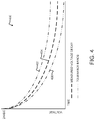
- FIG. 4 illustrates a graph of measured voltage decay for a health check of the uninterruptible power supply 190 .
- Periodically a health check of the ultracapacitor cells 194 is necessary to give confidence the uninterruptible power supply 190 can deliver backup power when necessary. This is achieved by switching the ultracapacitor cells 194 to connect to a load of known resistance (e.g., a power resistor).
- the voltage decay 404 is then measured against the expected decay curve for the load, within certain tolerance bands 402 , 406 , and the general health of the uninterruptible power supply 190 can then be ascertained.
- the voltage decay 404 may be measured against a single one of the tolerance bands, tolerance band 406 , such that the general health of the uninterruptible power supply 190 can be ascertained.
- FIG. 5 illustrates a flow diagram of one embodiment of a method 500 for controlling an uninterruptible power supply 190 of an electrical power system according to the present disclosure.
- the method 500 can include converting an AC power at a line-side converter 168 to a DC power for a DC link 136 , at block 502 .
- the method 500 also includes storing power from the DC link 136 in the uninterruptible power supply 190 , at block 504 .
- the ultracapacitor cells 194 may be charged with DC voltage from the power supply 236 .
- the method 500 also includes periodically performing a health check on a rate of decay of a power storage element (e.g., the ultracapacitor cells 194 ) in the uninterruptible power supply 194 with health check circuitry 192 , at block 506 .
- a power storage element e.g., the ultracapacitor cells 194
- the health check may be performed as described with reference to FIG. 4 .
- performing the health check on the rate of decay can include coupling the power storage element 194 to a resistance of known value (e.g., a power resistor) and measuring the rate of decay 404 over time. Then, the measured rate of decay can be compared against a set of tolerance decay bands 402 , 406 , or at least one of the tolerance decay bands 406 .
- a resistance of known value e.g., a power resistor
- the method 500 further includes sensing a first condition in the AC power, at block 508 , and, disabling the health check in response to sensing the first condition, at block 510 .
- the method 500 also includes disabling the health check circuitry 192 in response to sensing the first condition.
- the first condition may include a full or partial power failure at any phase of the 3-phase power buses illustrated in FIG. 1 .
- the first condition is sensed at a first phase of a power bus.
- an uninterruptible power supply may be integrated with an electrical power system.
- the uninterruptible power supply may include a health check circuit that periodically verifies the health of a power storage element, or elements, contained therein.
- the health check circuit and associated functions may be disabled and disabled using a health check disable component, such as a relay, to ensure power is always supplied to a control system of the electrical power system during a power failure.
- Example embodiments of a wind turbine, a control system for a wind turbine, and methods of controlling a wind turbine are described above in detail.
- the methods, wind turbine, and control system are not limited to the specific embodiments described herein, but rather, components of the wind turbine and/or the control system and/or steps of the methods may be utilized independently and separately from other components and/or steps described herein.
- the control system and methods may also be used in combination with other wind turbine power systems and methods, and are not limited to practice with only the power system as described herein.
- the exemplary embodiment can be implemented and utilized in connection with many other wind turbine or power system applications, such as solar power systems and energy storage systems.
Landscapes
- Engineering & Computer Science (AREA)
- Power Engineering (AREA)
- General Physics & Mathematics (AREA)
- Physics & Mathematics (AREA)
- Business, Economics & Management (AREA)
- Emergency Management (AREA)
- Sustainable Energy (AREA)
- Chemical & Material Sciences (AREA)
- Combustion & Propulsion (AREA)
- Mechanical Engineering (AREA)
- General Engineering & Computer Science (AREA)
- Sustainable Development (AREA)
- Life Sciences & Earth Sciences (AREA)
- Control Of Eletrric Generators (AREA)
- Inverter Devices (AREA)
Abstract
Description
- The present disclosure relates generally to electrical power systems, and more particular to a system and method for controlling an uninterruptible power supply of an electrical power system.
- Wind power is considered one of the cleanest, most environmentally friendly energy sources presently available, and wind turbines have gained increased attention in this regard. A modern wind turbine typically includes a tower, generator, gearbox, nacelle, and one or more rotor blades. The rotor blades capture kinetic energy of wind using known airfoil principles. For example, rotor blades typically have the cross-sectional profile of an airfoil such that, during operation, air flows over the blade producing a pressure difference between the sides. Consequently, a lift force, which is directed from a pressure side towards a suction side, acts on the blade. The lift force generates torque on the main rotor shaft, which is geared to a generator for producing electricity.
- During operation, wind impacts the rotor blades of the wind turbine and the blades transform wind energy into a mechanical rotational torque that rotatably drives a low-speed shaft. The low-speed shaft is configured to drive the gearbox that subsequently steps up the low rotational speed of the low-speed shaft to drive a high-speed shaft at an increased rotational speed. The high-speed shaft is generally rotatably coupled to a generator so as to rotatably drive a generator rotor. As such, a rotating magnetic field may be induced by the generator rotor and a voltage may be induced within a generator stator that is magnetically coupled to the generator rotor. In certain configurations, the associated electrical power can be transmitted to a turbine transformer that is typically connected to a power grid via a grid breaker. Thus, the turbine transformer steps up the voltage amplitude of the electrical power such that the transformed electrical power may be further transmitted to the power grid.
- In many wind turbines, the generator rotor may be electrically coupled to a bi-directional power converter that includes a rotor side converter joined to a line side converter via a regulated DC link. More specifically, some wind turbines, such as wind-driven doubly-fed induction generator (DFIG) systems or full power conversion systems, may include a power converter with an AC-DC-AC topology. In such system, the generator stator is separately connected to the power grid via a main transformer.
- The power converter usually includes several switching devices such as insulated gate bipolar transistors (IGBTs), integrated gate commutated thyristors (IGCTs or GCTs), diodes, or metal oxide semiconductor field effect transistors (MOSFETs) that are switched at certain frequencies to generate the desired converter output voltage and frequency. The converter output voltage is then provided to various loads such as motors, power grids, resistive loads, etc.
- Some grid and/or wind conditions can cause a full or partial power failure which disrupts power to the switching devices, which then disables the power converter. Such power failures are undesirable and can cause maintenance issues. Typical solutions involve large, heavy, lead-acid battery-based back-up power supplies to provide power to the control system, thereby retaining operation of the power converter during power failures. However, these lead-acid battery systems involve increased cost and complexity in integration. Other controllable systems may be more desirable.
- Aspects and advantages of the invention will be set forth in part in the following description, or may be obvious from the description, or may be learned through practice of the invention.
- According to one aspect, an electrical power system connected to a power grid can include a generator comprising a stator and a rotor, the stator connected to the power grid via a stator power path, a power converter coupled to a rotor bus of the rotor, and a control system comprising one or more control devices, the one or more control devices configured to operate the power converter to provide an AC signal for the rotor bus. The system can also include an uninterruptible power supply (UPS). The UPS can include a power storage element configured to receive and store electrical power, and configured to power the control system during a power failure, and, a health check circuit configured to verify a health status of the power storage element, and including a health check disable component configured to disable the health check circuit during the power failure.
- According to an additional aspect, a method of operating an uninterruptible power supply for a doubly fed induction generator system is described. The method can include converting an AC power at a line-side converter to a DC power for a DC link, storing power in the uninterruptible power supply, performing a health check on a rate of decay of a power storage element in the uninterruptible power supply with health check circuitry, sensing a first condition in the AC power, and, disabling the health check in response to sensing the first condition.
- According to yet another aspect, a wind turbine system can include a generator having a stator and a rotor, the stator connected to the power grid via a stator power path. The system can also include a power converter having a line-side converter coupled to the power grid via a converter power path, and, a rotor-side converter coupled to a rotor bus of the rotor and the line-side converter via a DC link. The system can also include a control system having one or more control devices, the one or more control devices configured to operate the rotor-side converter to provide the AC signal for the rotor bus. The system can also include an uninterruptible power supply including a power storage element configured to receive and store electrical power, and configured to power the control system during a power failure, and, a health check circuit configured to verify a health status of the power storage element, and including a health check disable component configured to disable the health check circuit during the power failure.
- These and other features, aspects and advantages of the present invention will become better understood with reference to the following description and appended claims. The accompanying drawings, which are incorporated in and constitute a part of this specification, illustrate embodiments of the invention and, together with the description, serve to explain the principles of the invention.
- A full and enabling disclosure of the present invention, including the best mode thereof, directed to one of ordinary skill in the art, is set forth in the specification, which makes reference to the appended figures, in which:
-
FIG. 1 illustrates one embodiment of an example electrical power system according to the present disclosure; -
FIG. 2 illustrates a block diagram of one embodiment of a control system suitable for use with the electrical power system shown inFIG. 1 ; -
FIG. 3 illustrates a block diagram of one embodiment of an uninterruptible power supply for use with the electrical power system shown inFIG. 1 ; -
FIG. 4 illustrates a graph of measured voltage decay for a health check of the uninterruptible power supply shown inFIG. 3 ; and -
FIG. 5 illustrates a flow diagram of one embodiment of a method for controlling an uninterruptible power supply of an electrical power system according to the present disclosure. - Reference now will be made in detail to embodiments of the invention, one or more examples of which are illustrated in the drawings. Each example is provided by way of explanation of the invention, not limitation of the invention. In fact, it will be apparent to those skilled in the art that various modifications and variations can be made in the present invention without departing from the scope or spirit of the invention. For instance, features illustrated or described as part of one embodiment can be used with another embodiment to yield a still further embodiment. Thus, it is intended that the present invention covers such modifications and variations as come within the scope of the appended claims and their equivalents.
- Example aspect of the present disclosure are directed to systems and methods for controlling uninterruptible power supplies of electrical power systems, such as DFIG power systems, using a health check circuit and a health check disable component. More specifically, example aspects of the present disclosure provide a system for controlling the uninterruptible power supply in response to various operating conditions, such as phase voltage, DC link voltage, DC link current, system current feedbacks, and/or system voltage feedbacks for the purpose of ensuring control system operation during a power failure with integrated health checks to ensure the health of the uninterruptible power supply. For example, the voltage decay of rechargeable power supply storage devices can be measured against tolerance bands to ensure healthy operation. In other instances, the health check can be disabled to ensure a control system is powered by the rechargeable power supply storage devices.
- In particular embodiments, the method for controlling the uninterruptible power supply may include disabling a health check and disabling health check circuitry in response to a sensed condition in AC power associated with the electrical power system. Further, the system and method may be applied to any electrical power system, including but not limiting to wind conversion systems, solar conversions systems, energy storage systems, and combinations thereof.
- Accordingly, the present disclosure has many technical effects and advantages. For example, the system and method of the present disclosure provides a higher system reliability (e.g. periodic health checks, etc.) as well as lower system cost (e.g. lower weight of components, lower cost of components, and/or lower maintenance costs).
- Referring now to the drawings,
FIG. 1 illustrates an example wind driven doubly-fed induction generator (DFIG)system 100 according to one embodiment of the present disclosure. Example aspects of the present disclosure are discussed with reference to the DFIGwind turbine 100 ofFIG. 1 for purposes of illustration and discussion. Those of ordinary skill in the art, using the disclosures provided herein, should understand that example aspects of the present disclosure are also applicable in other power systems, such as a wind, solar, gas turbine, or other suitable power generation systems. - In the
example system 100, arotor 106 includes a plurality ofrotor blades 108 coupled to arotatable hub 110. Therotatable hub 110 is coupled to anoptional gearbox 118, which is, in turn, coupled to agenerator 120 having arotor 122 and astator 124. In accordance with aspects of the present disclosure, thegenerator 120 may be any suitable generator, including for example, a doubly fed induction generator (DFIG). Thegenerator 120 is typically coupled to astator bus 154 and apower converter 162 via arotor bus 156. Thestator bus 154 provides an output multiphase power (e.g. three-phase power) from a stator of thegenerator 120 and therotor bus 156 provides an output multiphase power (e.g. three-phase power) of a rotor of thegenerator 120. - The
power converter 162 includes a rotor-side converter 166 coupled to a line-side converter 168. TheDFIG 120 is coupled to the rotor-side converter 166 via therotor bus 156. The line-side converter 168 is coupled to a line-side bus 188. Further, as shown, thestator bus 154 may be directly connected to the line-side bus 188. In example configurations, the rotor-side converter 166 and the line-side converter 168 are configured for normal operating mode in a three-phase, PWM arrangement using insulated gate bipolar transistor (IGBT) switching devices. The rotor-side converter 166 and the line-side converter 168 can be coupled via aDC link 136 across which is theDC link capacitor 138. In alternative embodiments, thestator bus 154 and thepower converter 162 may be connected to separate isolated windings of a transformer (not shown), i.e. at the junction of thegenerator breaker 158 and theconverter breaker 186. - The
power converter 162 can be coupled to acontrol system 174 to control the operation of the rotor-side converter 166 and the line-side converter 168 and other aspects of thepower system 100. For example, as shown particularly inFIG. 2 , thecontrol system 174 can include any number of control devices. In one implementation, for example, thecontrol system 174 can include one or more processor(s) 176 and associated memory device(s) 178 configured to perform a variety of computer-implemented functions and/or instructions (e.g., performing the methods, steps, calculations and the like and storing relevant data as disclosed herein). The instructions when executed by theprocessor 176 can cause theprocessor 176 to perform operations, including providing control commands (e.g. pulse width modulation commands) to the switching devices of thepower converter 162 and other aspects of thepower system 100. Additionally, thecontrol system 174 may also include acommunications module 180 to facilitate communications between thecontrol system 174 and the various components of thepower system 100, e.g. any of the components ofFIG. 1 . Further, thecommunications module 180 may include a sensor interface 182 (e.g., one or more analog-to-digital converters) to permit signals transmitted from one or more sensors to be converted into signals that can be understood and processed by theprocessors 176. It should be appreciated that the sensors may be communicatively coupled to thecommunications module 180 using any suitable means. For example, the sensors can be coupled to thesensor interface 182 via a wired connection. However, in other embodiments, the sensors may be coupled to thesensor interface 182 via a wireless connection, such as by using any suitable wireless communications protocol known in the art. As such, theprocessor 176 may be configured to receive one or more signals from the sensors. - As used herein, the term “processor” refers not only to integrated circuits referred to in the art as being included in a computer, but also refers to a controller, a microcontroller, a microcomputer, a programmable logic controller (PLC), an application specific integrated circuit, and other programmable circuits. The
processor 176 is also configured to compute advanced control algorithms and communicate to a variety of Ethernet or serial-based protocols (Modbus, OPC, CAN, etc.). Additionally, the memory device(s) 178 may generally comprise memory element(s) including, but not limited to, computer readable medium (e.g., random access memory (RAM)), computer readable non-volatile medium (e.g., a flash memory), a floppy disk, a compact disc-read only memory (CD-ROM), a magneto-optical disk (MOD), a digital versatile disc (DVD) and/or other suitable memory elements. Such memory device(s) 178 may generally be configured to store suitable computer-readable instructions that, when implemented by the processor(s) 176, configure thecontrol system 174 to perform the various functions as described herein. - Turning back to
FIG. 1 , during operation, alternating current power generated at theDFIG 120 by rotation of therotor 106 is provided via a dual path to anelectrical grid 160. The dual paths are defined by agenerator power path 130 and aconverter power path 132. On theconverter power path 132, sinusoidal multi-phase (e.g. three-phase) alternating current (AC) power is provided to thepower converter 162 via therotor bus 156. - The rotor-
side power converter 166 converts the AC power provided from therotor bus 156 into direct current (DC) power and provides the DC power to theDC link 136. Switching devices (e.g. IGBTs) used in bridge circuits of the rotorside power converter 166 can be modulated to convert the AC power provided from therotor bus 156 into DC power suitable for theDC link 136. - The line-
side converter 168 converts the DC power on the DC link 136 into AC output power suitable for theelectrical grid 160. In particular, switching devices (e.g. IGBTs) used in bridge circuits of the line-side power converter 168 can be modulated to convert the DC power on the DC link 136 into AC power on the line-side bus 188. The AC power from thepower converter 162 can be combined with the power from the stator of theDFIG 120 to provide multi-phase power (e.g. three-phase power) having a frequency maintained substantially at the frequency of the electrical grid 160 (e.g. 50 Hz/60 Hz). - Various circuit breakers and switches, such as a
generator breaker 158 andconverter breaker 186, can be included in thesystem 100 to connect or disconnect corresponding buses, for example, when current flow is excessive and can damage components of thewind turbine system 100 or for other operational considerations. Additional protection components can also be included in thewind turbine system 100. - The
power converter 162 can receive control signals from, for instance, thecontrol system 174. The control signals can be based, among other things, on sensed conditions or operating characteristics of thewind turbine system 100. Typically, the control signals provide for control of the operation of thepower converter 162. For example, feedback in the form of sensed speed of theDFIG 120 can be used to control the conversion of the output power from therotor bus 156 to maintain a proper and balanced multi-phase (e.g. three-phase) power supply. Other feedback from other sensors can also be used by thecontrol system 174 to control thepower converter 162, including, for example, stator and rotor bus voltages and current feedbacks. Using the various forms of feedback information, switching control signals (e.g. gate timing commands for IGBTs), stator synchronizing control signals, and circuit breaker signals can be generated. - As further illustrated, an
uninterruptible power supply 190 may be configured to receive and store electrical power and power thecontrol system 174 in the event of a power failure, partial power failure, or sensed power condition (e.g., an under-current or under-voltage condition). As used herein, a power failure refers to a condition where electrical power has been disrupted for more than about 1 second. Furthermore, a partial power failure refers to a condition where at least one phase of electrical power has been disrupted for more than about 1 second. Additionally, a sensed power condition can include a power failure or a partial power failure, as well as a sensed under-voltage or under-current condition. A sensed under-voltage condition can include any condition where electrical voltage has been reduced to under nominal voltage, or to under about 90% of nominal voltage (e.g., a 10% reduction). A sensed under-current condition can include any condition where electrical current has been reduced to under nominal current, or to under about 90% of nominal current (e.g., a 10% reduction). Theuninterruptible power supply 190 may include ahealth check circuit 192 or health check circuitry configured to verify the healthy operation of power cells contained in theuninterruptible power supply 190. Theuninterruptible power supply 190 may also include a power storage element configured to receive and store electrical power received from at least one phase of AC electrical power from the generator 120 (illustrated inFIG. 3 ). For example, the uninterruptible power supply may receive power from a power supply (e.g., 24 VDC power supply) in electrical communication with an auxiliary tap of a main transformer of thewind turbine 100. - Referring now to
FIG. 3 , a block diagram of theuninterruptible power supply 190 is provided. As shown, theuninterruptible power supply 190 is configured to sense at least one phase of power from a three-phase bus 188 of thesystem 100. It should be understood that voltage/current feedback from any phase is possible. Accordingly, for the purposes of clarity in discussion, a particular phase has been illustrated as being sensed. In other implementations, other phases or multiple phases may be sensed to determine a power condition such as failure, under-current, or under-voltage. - The
uninterruptible power supply 190 can include thehealth check 192 described above. Thehealth check circuit 192 can include a health check disablecomponent 193 configured to disable a health check and disable thehealth check circuit 192. The health check disablecomponent 193 can be a relay, such as an electro-mechanical relay or solid state relay configured to interrupt a health check by physically disconnecting thehealth check circuit 190 from power cells 194. In this manner, any health check being performed on power cells 194 is immediately ceased such that the power cells 194 can be used to power thecontrol system 174 withleads 274 instead. - The health check circuit 194 further includes a
power failure component 195. Thepower failure component 195 is configured to aid in performing a health check. For example, the power failure component may include a relay, such as an electro-mechanical relay or solid state relay. Thehealth check circuit 192 also includespower resistor 197 of a known value. During a health check, therelay 195 physically connects the cells 194 to thispower resistor 197, and the rate of voltage decay is monitored by the control system (through 275) to determine if the cells are healthy or not. - It should be understood that although described as being singular relays in one embodiment, the
components - Generally, the power cells 194 may include any suitable power cells. For example, according to at least one embodiment, the power cells 194 are a number of series-connected or parallel-connected ultracapacitor cells. In one particular example, the ultracapacitor cells have a storage capacity of at least 300 Farads and are coupled in series.
- As further shown, the
uninterruptible power supply 190 further includes a plurality of balancingresistors 196. The plurality of balancingresistors 196 may be coupled to the bank of ultracapacitors 194. In this regard, the plurality of balancingresistors 196 are configured to distribute voltage imbalance across the bank of ultracapacitors 194. In one embodiment, each balancing resistor of the plurality of balancingresistors 196 is coupled across an individual ultracapacitor of the bank of ultracapacitors 194. For example, the individual resistors may be connected across terminals of each individual capacitor cell, to distribute voltage imbalance caused by varying levels of capacitance in a series chain. Other connections may be possible depending upon the particular configuration of the bank of ultracapacitors. - As further shown, the
control system 174 is configured to monitor theuninterruptible power supply 190 via a voltage divider circuit 198 coupled to the power storage cells 194 and/or balancingresistors 196. For example, feedback signals of the + and − legs of theuninterruptible power supply 190 are monitored by thecontrol system 174 through the voltage divider circuit 198 at 275. Thecontrol system 174 may have an analog input voltage range that is limited. Thus, the voltage divider circuit 198 can drop down the stored voltage to fall within the control system's range. - As described above, the
health check circuit 192 is operative to evaluate the health of theuninterruptible power supply 190, and more particularly, the ultracapacitor cells 194.FIG. 4 illustrates a graph of measured voltage decay for a health check of theuninterruptible power supply 190. Periodically a health check of the ultracapacitor cells 194 is necessary to give confidence theuninterruptible power supply 190 can deliver backup power when necessary. This is achieved by switching the ultracapacitor cells 194 to connect to a load of known resistance (e.g., a power resistor). Thevoltage decay 404 is then measured against the expected decay curve for the load, withincertain tolerance bands uninterruptible power supply 190 can then be ascertained. According to another embodiment, thevoltage decay 404 may be measured against a single one of the tolerance bands,tolerance band 406, such that the general health of theuninterruptible power supply 190 can be ascertained. -
FIG. 5 illustrates a flow diagram of one embodiment of amethod 500 for controlling anuninterruptible power supply 190 of an electrical power system according to the present disclosure. Themethod 500 can include converting an AC power at a line-side converter 168 to a DC power for aDC link 136, atblock 502. - The
method 500 also includes storing power from the DC link 136 in theuninterruptible power supply 190, atblock 504. For example, the ultracapacitor cells 194 may be charged with DC voltage from thepower supply 236. - The
method 500 also includes periodically performing a health check on a rate of decay of a power storage element (e.g., the ultracapacitor cells 194) in the uninterruptible power supply 194 withhealth check circuitry 192, atblock 506. - The health check may be performed as described with reference to
FIG. 4 . For example, performing the health check on the rate of decay can include coupling the power storage element 194 to a resistance of known value (e.g., a power resistor) and measuring the rate ofdecay 404 over time. Then, the measured rate of decay can be compared against a set oftolerance decay bands tolerance decay bands 406. - The
method 500 further includes sensing a first condition in the AC power, atblock 508, and, disabling the health check in response to sensing the first condition, atblock 510. Themethod 500 also includes disabling thehealth check circuitry 192 in response to sensing the first condition. Generally, the first condition may include a full or partial power failure at any phase of the 3-phase power buses illustrated inFIG. 1 . According to at least one embodiment, the first condition is sensed at a first phase of a power bus. - As described above, an uninterruptible power supply may be integrated with an electrical power system. The uninterruptible power supply may include a health check circuit that periodically verifies the health of a power storage element, or elements, contained therein. Furthermore, the health check circuit and associated functions may be disabled and disabled using a health check disable component, such as a relay, to ensure power is always supplied to a control system of the electrical power system during a power failure.
- Example embodiments of a wind turbine, a control system for a wind turbine, and methods of controlling a wind turbine are described above in detail. The methods, wind turbine, and control system are not limited to the specific embodiments described herein, but rather, components of the wind turbine and/or the control system and/or steps of the methods may be utilized independently and separately from other components and/or steps described herein. For example, the control system and methods may also be used in combination with other wind turbine power systems and methods, and are not limited to practice with only the power system as described herein. Rather, the exemplary embodiment can be implemented and utilized in connection with many other wind turbine or power system applications, such as solar power systems and energy storage systems.
- Although specific features of various embodiments of the invention may be shown in some drawings and not in others, this is for convenience only. In accordance with the principles of the invention, any feature of a drawing may be referenced and/or claimed in combination with any feature of any other drawing.
- This written description uses examples to disclose the invention, including the best mode, and also to enable any person skilled in the art to practice the invention, including making and using any devices or systems and performing any incorporated methods. The patentable scope of the invention is defined by the claims, and may include other examples that occur to those skilled in the art. Such other examples are intended to be within the scope of the claims if they include structural elements that do not differ from the literal language of the claims, or if they include equivalent structural elements with insubstantial differences from the literal languages of the claims.
Claims (20)
Priority Applications (5)
| Application Number | Priority Date | Filing Date | Title |
|---|---|---|---|
| US16/144,409 US10998760B2 (en) | 2018-09-27 | 2018-09-27 | System and method for controlling uninterruptible power supply of electrical power systems |
| DK19200163.4T DK3629440T3 (en) | 2018-09-27 | 2019-09-27 | SYSTEM AND METHOD FOR CONTROLLING INTERRUPTED POWER SUPPLY OF ELECTRIC POWER SYSTEMS |
| ES19200163T ES2902140T3 (en) | 2018-09-27 | 2019-09-27 | System and method for controlling an uninterruptible power supply of electrical power systems |
| CN201910922057.XA CN110957753A (en) | 2018-09-27 | 2019-09-27 | System and method for controlling an uninterrupted power source of an electrical power system |
| EP19200163.4A EP3629440B1 (en) | 2018-09-27 | 2019-09-27 | System and method for controlling uninterruptible power supply of electrical power systems |
Applications Claiming Priority (1)
| Application Number | Priority Date | Filing Date | Title |
|---|---|---|---|
| US16/144,409 US10998760B2 (en) | 2018-09-27 | 2018-09-27 | System and method for controlling uninterruptible power supply of electrical power systems |
Publications (2)
| Publication Number | Publication Date |
|---|---|
| US20200106295A1 true US20200106295A1 (en) | 2020-04-02 |
| US10998760B2 US10998760B2 (en) | 2021-05-04 |
Family
ID=68084639
Family Applications (1)
| Application Number | Title | Priority Date | Filing Date |
|---|---|---|---|
| US16/144,409 Active 2039-04-25 US10998760B2 (en) | 2018-09-27 | 2018-09-27 | System and method for controlling uninterruptible power supply of electrical power systems |
Country Status (5)
| Country | Link |
|---|---|
| US (1) | US10998760B2 (en) |
| EP (1) | EP3629440B1 (en) |
| CN (1) | CN110957753A (en) |
| DK (1) | DK3629440T3 (en) |
| ES (1) | ES2902140T3 (en) |
Cited By (9)
| Publication number | Priority date | Publication date | Assignee | Title |
|---|---|---|---|---|
| US20200144826A1 (en) * | 2018-11-06 | 2020-05-07 | General Electric Company | System and Method for Wind Power Generation and Transmission in Electrical Power Systems |
| CN112196739A (en) * | 2020-10-10 | 2021-01-08 | 国电联合动力技术有限公司 | Wind generating set uninterrupted power supply intelligent regulation and control system and method |
| WO2023201214A3 (en) * | 2022-04-12 | 2023-12-14 | Mark Daniel Farb | Systems and methods for operating a cluster of fluid turbines |
| US12025100B2 (en) | 2022-02-08 | 2024-07-02 | Flower Turbines, Inc. | Common brake for a cluster of turbines |
| US12126176B2 (en) | 2022-08-28 | 2024-10-22 | Flower Turbines, Inc. | Step gradations for a charge controller of a fluid turbine |
| US12180934B2 (en) | 2023-01-15 | 2024-12-31 | Flower Turbines, Inc. | Flat-packable kit for a turbine |
| US12199437B2 (en) | 2022-04-12 | 2025-01-14 | Flower Turbines, Inc. | Dual mode turbine collects energy during low wind conditions |
| US12228105B2 (en) | 2023-04-09 | 2025-02-18 | Flower Turbines, Inc. | Flat roof green energy support structure |
| US12276208B2 (en) | 2022-09-18 | 2025-04-15 | Flower Turbines, Inc. | Sleeves for turbine shafts |
Families Citing this family (1)
| Publication number | Priority date | Publication date | Assignee | Title |
|---|---|---|---|---|
| US11996236B2 (en) * | 2021-05-26 | 2024-05-28 | Eaton Intelligent Power Limited | Current balancing apparatus and methods for parallel connected circuit breakers |
Citations (17)
| Publication number | Priority date | Publication date | Assignee | Title |
|---|---|---|---|---|
| US5886503A (en) * | 1996-05-29 | 1999-03-23 | Peco Ii, Inc. | Back-up battery management apparatus for charging and testing individual battery cells in a string of battery cells |
| US20060214428A1 (en) * | 2003-06-16 | 2006-09-28 | Repower Systems Ag | Wind farm |
| US20080296975A1 (en) * | 2007-06-04 | 2008-12-04 | Walter Jeffrey Shakespeare | Back-up power system |
| US20090066089A1 (en) * | 2006-02-28 | 2009-03-12 | Mitsubishi Heavy Industries, Ltd. | Wind Power Generator System and Control Method of the Same |
| US20090278354A1 (en) * | 2008-05-09 | 2009-11-12 | Hitachi, Ltd. | Wind turbine generator system |
| US20090302608A1 (en) * | 2008-06-09 | 2009-12-10 | Gamesa Innovation & Technology , S.L. | Wind power installation and method of modifying the blade pitch in a wind power installation |
| US20100213712A1 (en) * | 2007-12-14 | 2010-08-26 | Mitsubishi Heavy Industries, Ltd. | Wind turbine generator |
| US20110001353A1 (en) * | 2009-07-02 | 2011-01-06 | Electrical Power Worx Corp. | Auxiliary power systems and methods thereof |
| US20110089694A1 (en) * | 2008-10-16 | 2011-04-21 | Mitsubishi Heavy Industries, Ltd. | Wind turbine generator system and control method of the same |
| US20110204630A1 (en) * | 2007-12-14 | 2011-08-25 | Mitsubishi Heavy Industries, Ltd. | Wind power generation system and operation control method thereof |
| US20120217824A1 (en) * | 2009-08-14 | 2012-08-30 | Amit Kumar Gupta | Variable speed wind turbine, and a method for operating the variable speed wind turbine during a power imbalance event |
| US8415818B2 (en) * | 2007-08-22 | 2013-04-09 | Woodward Kempen Gmbh | Method of and apparatus for compensation of oscillation effects in the event of mains asymmetry in a double-fed asynchronous machine |
| US20130184884A1 (en) * | 2011-07-20 | 2013-07-18 | Inventus Holdings, Llc | Dispatchable renewable energy generation, control and storage facility |
| US20130181450A1 (en) * | 2012-01-17 | 2013-07-18 | Kasibhatla Satish NARAYANA | Method for operating a wind turbine |
| US20150180273A1 (en) * | 2013-12-23 | 2015-06-25 | General Electric Company | Optimized filter for battery energy storage on alternate energy systems |
| US20180191236A1 (en) * | 2017-01-05 | 2018-07-05 | General Electric Company | Filter Device for Power Converters with Silicon Carbide Mosfets |
| US20190280508A1 (en) * | 2018-03-07 | 2019-09-12 | Isac Tabib | Smart Uninterruptible Power Supply And Method |
Family Cites Families (19)
| Publication number | Priority date | Publication date | Assignee | Title |
|---|---|---|---|---|
| US6316917B1 (en) | 1999-03-09 | 2001-11-13 | Asahi Glass Company, Limited | Apparatus having plural electric double layer capacitors and method for adjusting voltages of the capacitors |
| JP2003032908A (en) | 2001-07-19 | 2003-01-31 | Nisshinbo Ind Inc | Capacitor assembled battery, control method therefor, control device therefor, and power storage system for automobile |
| US6921985B2 (en) | 2003-01-24 | 2005-07-26 | General Electric Company | Low voltage ride through for wind turbine generators |
| US20060018073A1 (en) | 2004-07-23 | 2006-01-26 | Maxwell Technologies, Inc. | Active protection against transients |
| US7602075B2 (en) | 2006-07-06 | 2009-10-13 | Acciona Windpower, S.A. | Systems, methods and apparatuses for a wind turbine controller |
| US7952232B2 (en) | 2008-03-13 | 2011-05-31 | General Electric Company | Wind turbine energy storage and frequency control |
| US9077201B2 (en) | 2009-05-29 | 2015-07-07 | Toshiba Mitsubishi-Electric Industrial Systems Corporation | Uninterruptible power supply device |
| CN101692502B (en) * | 2009-09-25 | 2011-08-17 | 深圳市航盛电子股份有限公司 | Battery management system |
| SE536419C2 (en) | 2010-06-02 | 2013-10-15 | Balancing of super capacitors | |
| DE102011079360A1 (en) | 2011-07-19 | 2013-01-24 | Sb Limotive Company Ltd. | Device and method for measuring a maximum cell voltage |
| WO2013099394A1 (en) * | 2011-12-28 | 2013-07-04 | 本田技研工業株式会社 | Vehicle diagnostic system, vehicle diagnostic method, and vehicle |
| US9966758B2 (en) | 2012-06-11 | 2018-05-08 | Panduit Corp. | Capacitor-based UPS |
| US9941687B2 (en) * | 2013-06-04 | 2018-04-10 | General Electric Company | Methods for operating wind turbine system having dynamic brake |
| CH708109B1 (en) | 2013-08-01 | 2014-12-15 | Chypsotech Gmbh Michael Müller | Uninterruptible Power Supply (UPS) for electronic devices. |
| US9667057B2 (en) * | 2014-06-18 | 2017-05-30 | General Electric Company | System and method for protecting a power converter during an adverse voltage event |
| CN105548899B (en) * | 2016-01-04 | 2019-03-01 | 朱建强 | A kind of battery management method and device of robot |
| US10003214B2 (en) | 2016-03-21 | 2018-06-19 | General Electric Company | Battery management system |
| EP3226380B1 (en) | 2016-03-31 | 2022-04-06 | Konica Minolta Business Solutions Europe GmbH | Uninterruptible power supply |
| CN107317386A (en) * | 2017-06-21 | 2017-11-03 | 江南大学 | Soil moisture content monitoring system energy supply based on wind light mutual complementing |
-
2018
- 2018-09-27 US US16/144,409 patent/US10998760B2/en active Active
-
2019
- 2019-09-27 DK DK19200163.4T patent/DK3629440T3/en active
- 2019-09-27 EP EP19200163.4A patent/EP3629440B1/en active Active
- 2019-09-27 CN CN201910922057.XA patent/CN110957753A/en active Pending
- 2019-09-27 ES ES19200163T patent/ES2902140T3/en active Active
Patent Citations (17)
| Publication number | Priority date | Publication date | Assignee | Title |
|---|---|---|---|---|
| US5886503A (en) * | 1996-05-29 | 1999-03-23 | Peco Ii, Inc. | Back-up battery management apparatus for charging and testing individual battery cells in a string of battery cells |
| US20060214428A1 (en) * | 2003-06-16 | 2006-09-28 | Repower Systems Ag | Wind farm |
| US20090066089A1 (en) * | 2006-02-28 | 2009-03-12 | Mitsubishi Heavy Industries, Ltd. | Wind Power Generator System and Control Method of the Same |
| US20080296975A1 (en) * | 2007-06-04 | 2008-12-04 | Walter Jeffrey Shakespeare | Back-up power system |
| US8415818B2 (en) * | 2007-08-22 | 2013-04-09 | Woodward Kempen Gmbh | Method of and apparatus for compensation of oscillation effects in the event of mains asymmetry in a double-fed asynchronous machine |
| US20110204630A1 (en) * | 2007-12-14 | 2011-08-25 | Mitsubishi Heavy Industries, Ltd. | Wind power generation system and operation control method thereof |
| US20100213712A1 (en) * | 2007-12-14 | 2010-08-26 | Mitsubishi Heavy Industries, Ltd. | Wind turbine generator |
| US20090278354A1 (en) * | 2008-05-09 | 2009-11-12 | Hitachi, Ltd. | Wind turbine generator system |
| US20090302608A1 (en) * | 2008-06-09 | 2009-12-10 | Gamesa Innovation & Technology , S.L. | Wind power installation and method of modifying the blade pitch in a wind power installation |
| US20110089694A1 (en) * | 2008-10-16 | 2011-04-21 | Mitsubishi Heavy Industries, Ltd. | Wind turbine generator system and control method of the same |
| US20110001353A1 (en) * | 2009-07-02 | 2011-01-06 | Electrical Power Worx Corp. | Auxiliary power systems and methods thereof |
| US20120217824A1 (en) * | 2009-08-14 | 2012-08-30 | Amit Kumar Gupta | Variable speed wind turbine, and a method for operating the variable speed wind turbine during a power imbalance event |
| US20130184884A1 (en) * | 2011-07-20 | 2013-07-18 | Inventus Holdings, Llc | Dispatchable renewable energy generation, control and storage facility |
| US20130181450A1 (en) * | 2012-01-17 | 2013-07-18 | Kasibhatla Satish NARAYANA | Method for operating a wind turbine |
| US20150180273A1 (en) * | 2013-12-23 | 2015-06-25 | General Electric Company | Optimized filter for battery energy storage on alternate energy systems |
| US20180191236A1 (en) * | 2017-01-05 | 2018-07-05 | General Electric Company | Filter Device for Power Converters with Silicon Carbide Mosfets |
| US20190280508A1 (en) * | 2018-03-07 | 2019-09-12 | Isac Tabib | Smart Uninterruptible Power Supply And Method |
Cited By (16)
| Publication number | Priority date | Publication date | Assignee | Title |
|---|---|---|---|---|
| US10826297B2 (en) * | 2018-11-06 | 2020-11-03 | General Electric Company | System and method for wind power generation and transmission in electrical power systems |
| US20200144826A1 (en) * | 2018-11-06 | 2020-05-07 | General Electric Company | System and Method for Wind Power Generation and Transmission in Electrical Power Systems |
| CN112196739A (en) * | 2020-10-10 | 2021-01-08 | 国电联合动力技术有限公司 | Wind generating set uninterrupted power supply intelligent regulation and control system and method |
| US12025100B2 (en) | 2022-02-08 | 2024-07-02 | Flower Turbines, Inc. | Common brake for a cluster of turbines |
| US12199437B2 (en) | 2022-04-12 | 2025-01-14 | Flower Turbines, Inc. | Dual mode turbine collects energy during low wind conditions |
| WO2023201214A3 (en) * | 2022-04-12 | 2023-12-14 | Mark Daniel Farb | Systems and methods for operating a cluster of fluid turbines |
| US12348046B2 (en) | 2022-04-12 | 2025-07-01 | Flower Turbines, Inc. | Dual mode turbine for supplying energy using a smart inverter |
| US12126176B2 (en) | 2022-08-28 | 2024-10-22 | Flower Turbines, Inc. | Step gradations for a charge controller of a fluid turbine |
| US12166355B2 (en) | 2022-08-28 | 2024-12-10 | Flower Turbines, Inc. | Application of machine learning to an MPPT protocol for a fluid turbine |
| US12276208B2 (en) | 2022-09-18 | 2025-04-15 | Flower Turbines, Inc. | Sleeves for turbine shafts |
| US12180934B2 (en) | 2023-01-15 | 2024-12-31 | Flower Turbines, Inc. | Flat-packable kit for a turbine |
| US12209571B2 (en) | 2023-01-15 | 2025-01-28 | Flower Turbines, Inc. | Positioning moveable flow turbines |
| US12352240B2 (en) | 2023-01-15 | 2025-07-08 | Flower Turbines, Inc. | Coordinating overlap of low pressure zones in adjacent turbines |
| US12228105B2 (en) | 2023-04-09 | 2025-02-18 | Flower Turbines, Inc. | Flat roof green energy support structure |
| US12305610B2 (en) | 2023-04-09 | 2025-05-20 | Flower Turbines, Inc. | Turbine powered by exhaust fan |
| US12362698B2 (en) | 2023-04-09 | 2025-07-15 | Flower Turbines, Inc. | Green sun-shaded charging stations |
Also Published As
| Publication number | Publication date |
|---|---|
| ES2902140T3 (en) | 2022-03-25 |
| EP3629440B1 (en) | 2021-09-22 |
| CN110957753A (en) | 2020-04-03 |
| US10998760B2 (en) | 2021-05-04 |
| DK3629440T3 (en) | 2022-01-03 |
| EP3629440A1 (en) | 2020-04-01 |
Similar Documents
| Publication | Publication Date | Title |
|---|---|---|
| US10998760B2 (en) | System and method for controlling uninterruptible power supply of electrical power systems | |
| CN103370873B (en) | The feather motor-drive circuit that can operate in the emergency mode | |
| US9617976B2 (en) | Systems and methods for increasing wind turbine power output | |
| US10519933B2 (en) | Method of operating a wind turbine system including an energy storage system | |
| US9337685B2 (en) | Optimized filter for battery energy storage on alternate energy systems | |
| US9231509B2 (en) | System and method for operating a power generation system within a power storage/discharge mode or a dynamic brake mode | |
| US20150372481A1 (en) | System and method for protecting a power converter during an adverse voltage event | |
| US10107260B2 (en) | Wind turbine auxiliary circuit control | |
| US10523088B2 (en) | Energy storage system for doubly fed induction generator | |
| US20150249414A1 (en) | Wind turbine systems and methods for operating the same | |
| EP3004637A1 (en) | Methods for operating wind turbine system having dynamic brake | |
| US10581247B1 (en) | System and method for reactive power control of wind turbines in a wind farm supported with auxiliary reactive power compensation | |
| US10855079B1 (en) | System and method for reducing oscillations in a renewable energy power system | |
| EP3893383A1 (en) | System and method for controlling wind turbine converters during high voltage ride through events | |
| EP3745551B1 (en) | System and method for controlling harmonics in a renewable energy power system | |
| CN102804592B (en) | The emergency adjustment device of the blade adjustment System of wind energy plant | |
| EP3961886A1 (en) | Crowbar module for an active neutral point clamped power conversion assembly | |
| EP3487066B1 (en) | System and method for operating a doubly fed induction generator system to reduce harmonics | |
| CN112443455B (en) | System and method for operating a wind turbine power system during low wind speeds | |
| JP5852441B2 (en) | Wind power generation system |
Legal Events
| Date | Code | Title | Description |
|---|---|---|---|
| AS | Assignment |
Owner name: GENERAL ELECTRIC COMPANY, NEW YORK Free format text: ASSIGNMENT OF ASSIGNORS INTEREST;ASSIGNOR:TRZEMZALSKI, JOSEPH ANDREW;REEL/FRAME:046997/0178 Effective date: 20180926 |
|
| FEPP | Fee payment procedure |
Free format text: ENTITY STATUS SET TO UNDISCOUNTED (ORIGINAL EVENT CODE: BIG.); ENTITY STATUS OF PATENT OWNER: LARGE ENTITY |
|
| STPP | Information on status: patent application and granting procedure in general |
Free format text: NON FINAL ACTION MAILED |
|
| STPP | Information on status: patent application and granting procedure in general |
Free format text: NOTICE OF ALLOWANCE MAILED -- APPLICATION RECEIVED IN OFFICE OF PUBLICATIONS |
|
| STPP | Information on status: patent application and granting procedure in general |
Free format text: PUBLICATIONS -- ISSUE FEE PAYMENT VERIFIED |
|
| STCF | Information on status: patent grant |
Free format text: PATENTED CASE |
|
| AS | Assignment |
Owner name: GE INFRASTRUCTURE TECHNOLOGY LLC, SOUTH CAROLINA Free format text: ASSIGNMENT OF ASSIGNORS INTEREST;ASSIGNOR:GENERAL ELECTRIC COMPANY;REEL/FRAME:065727/0001 Effective date: 20231110 Owner name: GE INFRASTRUCTURE TECHNOLOGY LLC, SOUTH CAROLINA Free format text: ASSIGNMENT OF ASSIGNOR'S INTEREST;ASSIGNOR:GENERAL ELECTRIC COMPANY;REEL/FRAME:065727/0001 Effective date: 20231110 |
|
| MAFP | Maintenance fee payment |
Free format text: PAYMENT OF MAINTENANCE FEE, 4TH YEAR, LARGE ENTITY (ORIGINAL EVENT CODE: M1551); ENTITY STATUS OF PATENT OWNER: LARGE ENTITY Year of fee payment: 4 |