US20200088198A1 - Scroll compressor - Google Patents
Scroll compressor Download PDFInfo
- Publication number
- US20200088198A1 US20200088198A1 US16/551,838 US201916551838A US2020088198A1 US 20200088198 A1 US20200088198 A1 US 20200088198A1 US 201916551838 A US201916551838 A US 201916551838A US 2020088198 A1 US2020088198 A1 US 2020088198A1
- Authority
- US
- United States
- Prior art keywords
- buffer member
- peripheral surface
- insertion groove
- shaft
- end insertion
- Prior art date
- Legal status (The legal status is an assumption and is not a legal conclusion. Google has not performed a legal analysis and makes no representation as to the accuracy of the status listed.)
- Granted
Links
Images


Classifications
-
- F—MECHANICAL ENGINEERING; LIGHTING; HEATING; WEAPONS; BLASTING
- F04—POSITIVE - DISPLACEMENT MACHINES FOR LIQUIDS; PUMPS FOR LIQUIDS OR ELASTIC FLUIDS
- F04C—ROTARY-PISTON, OR OSCILLATING-PISTON, POSITIVE-DISPLACEMENT MACHINES FOR LIQUIDS; ROTARY-PISTON, OR OSCILLATING-PISTON, POSITIVE-DISPLACEMENT PUMPS
- F04C29/00—Component parts, details or accessories of pumps or pumping installations, not provided for in groups F04C18/00 - F04C28/00
- F04C29/0042—Driving elements, brakes, couplings, transmissions specially adapted for pumps
- F04C29/005—Means for transmitting movement from the prime mover to driven parts of the pump, e.g. clutches, couplings, transmissions
- F04C29/0057—Means for transmitting movement from the prime mover to driven parts of the pump, e.g. clutches, couplings, transmissions for eccentric movement
-
- F—MECHANICAL ENGINEERING; LIGHTING; HEATING; WEAPONS; BLASTING
- F04—POSITIVE - DISPLACEMENT MACHINES FOR LIQUIDS; PUMPS FOR LIQUIDS OR ELASTIC FLUIDS
- F04C—ROTARY-PISTON, OR OSCILLATING-PISTON, POSITIVE-DISPLACEMENT MACHINES FOR LIQUIDS; ROTARY-PISTON, OR OSCILLATING-PISTON, POSITIVE-DISPLACEMENT PUMPS
- F04C18/00—Rotary-piston pumps specially adapted for elastic fluids
- F04C18/02—Rotary-piston pumps specially adapted for elastic fluids of arcuate-engagement type, i.e. with circular translatory movement of co-operating members, each member having the same number of teeth or tooth-equivalents
- F04C18/0207—Rotary-piston pumps specially adapted for elastic fluids of arcuate-engagement type, i.e. with circular translatory movement of co-operating members, each member having the same number of teeth or tooth-equivalents both members having co-operating elements in spiral form
- F04C18/0215—Rotary-piston pumps specially adapted for elastic fluids of arcuate-engagement type, i.e. with circular translatory movement of co-operating members, each member having the same number of teeth or tooth-equivalents both members having co-operating elements in spiral form where only one member is moving
-
- F—MECHANICAL ENGINEERING; LIGHTING; HEATING; WEAPONS; BLASTING
- F04—POSITIVE - DISPLACEMENT MACHINES FOR LIQUIDS; PUMPS FOR LIQUIDS OR ELASTIC FLUIDS
- F04C—ROTARY-PISTON, OR OSCILLATING-PISTON, POSITIVE-DISPLACEMENT MACHINES FOR LIQUIDS; ROTARY-PISTON, OR OSCILLATING-PISTON, POSITIVE-DISPLACEMENT PUMPS
- F04C18/00—Rotary-piston pumps specially adapted for elastic fluids
- F04C18/02—Rotary-piston pumps specially adapted for elastic fluids of arcuate-engagement type, i.e. with circular translatory movement of co-operating members, each member having the same number of teeth or tooth-equivalents
- F04C18/063—Rotary-piston pumps specially adapted for elastic fluids of arcuate-engagement type, i.e. with circular translatory movement of co-operating members, each member having the same number of teeth or tooth-equivalents with coaxially-mounted members having continuously-changing circumferential spacing between them
-
- F—MECHANICAL ENGINEERING; LIGHTING; HEATING; WEAPONS; BLASTING
- F04—POSITIVE - DISPLACEMENT MACHINES FOR LIQUIDS; PUMPS FOR LIQUIDS OR ELASTIC FLUIDS
- F04C—ROTARY-PISTON, OR OSCILLATING-PISTON, POSITIVE-DISPLACEMENT MACHINES FOR LIQUIDS; ROTARY-PISTON, OR OSCILLATING-PISTON, POSITIVE-DISPLACEMENT PUMPS
- F04C27/00—Sealing arrangements in rotary-piston pumps specially adapted for elastic fluids
- F04C27/005—Axial sealings for working fluid
- F04C27/006—Elements specially adapted for sealing of the lateral faces of intermeshing-engagement type pumps, e.g. gear pumps
-
- F—MECHANICAL ENGINEERING; LIGHTING; HEATING; WEAPONS; BLASTING
- F04—POSITIVE - DISPLACEMENT MACHINES FOR LIQUIDS; PUMPS FOR LIQUIDS OR ELASTIC FLUIDS
- F04C—ROTARY-PISTON, OR OSCILLATING-PISTON, POSITIVE-DISPLACEMENT MACHINES FOR LIQUIDS; ROTARY-PISTON, OR OSCILLATING-PISTON, POSITIVE-DISPLACEMENT PUMPS
- F04C29/00—Component parts, details or accessories of pumps or pumping installations, not provided for in groups F04C18/00 - F04C28/00
- F04C29/0021—Systems for the equilibration of forces acting on the pump
-
- F—MECHANICAL ENGINEERING; LIGHTING; HEATING; WEAPONS; BLASTING
- F04—POSITIVE - DISPLACEMENT MACHINES FOR LIQUIDS; PUMPS FOR LIQUIDS OR ELASTIC FLUIDS
- F04C—ROTARY-PISTON, OR OSCILLATING-PISTON, POSITIVE-DISPLACEMENT MACHINES FOR LIQUIDS; ROTARY-PISTON, OR OSCILLATING-PISTON, POSITIVE-DISPLACEMENT PUMPS
- F04C2240/00—Components
- F04C2240/60—Shafts
-
- F—MECHANICAL ENGINEERING; LIGHTING; HEATING; WEAPONS; BLASTING
- F04—POSITIVE - DISPLACEMENT MACHINES FOR LIQUIDS; PUMPS FOR LIQUIDS OR ELASTIC FLUIDS
- F04C—ROTARY-PISTON, OR OSCILLATING-PISTON, POSITIVE-DISPLACEMENT MACHINES FOR LIQUIDS; ROTARY-PISTON, OR OSCILLATING-PISTON, POSITIVE-DISPLACEMENT PUMPS
- F04C2240/00—Components
- F04C2240/80—Other components
- F04C2240/807—Balance weight, counterweight
-
- F—MECHANICAL ENGINEERING; LIGHTING; HEATING; WEAPONS; BLASTING
- F04—POSITIVE - DISPLACEMENT MACHINES FOR LIQUIDS; PUMPS FOR LIQUIDS OR ELASTIC FLUIDS
- F04C—ROTARY-PISTON, OR OSCILLATING-PISTON, POSITIVE-DISPLACEMENT MACHINES FOR LIQUIDS; ROTARY-PISTON, OR OSCILLATING-PISTON, POSITIVE-DISPLACEMENT PUMPS
- F04C29/00—Component parts, details or accessories of pumps or pumping installations, not provided for in groups F04C18/00 - F04C28/00
- F04C29/06—Silencing
Definitions
- Exemplary embodiments of the present disclosure relate to a scroll compressor, and more particularly, to a scroll compressor capable of compressing a refrigerant with a fixed scroll and an orbiting scroll.
- a vehicle is equipped with an air conditioning (A/C) system for cooling/heating the interior thereof.
- This air conditioning system includes a compressor that is a component of a cooling system and compresses the low-temperature and low-pressure gas-phase refrigerant, introduced from an evaporator, to a high-temperature and high-pressure gas-phase refrigerant to send it to a condenser.
- Examples of the compressor include a reciprocating compressor that compresses a refrigerant according to which pistons reciprocate, and a rotary compressor that compresses a refrigerant while rotating.
- the reciprocating compressor includes a crank compressor that transmits a driving force from a drive source to a plurality of pistons using a crank, a swash plate compressor that transmits a driving force from a drive source to a shaft installed with a swash plate, and the like, according to the power transmission from the drive source.
- the rotary compressor includes a vane rotary compressor that utilizes a rotating rotary shaft and vane, and a scroll compressor that utilizes an orbiting scroll and a fixed scroll.
- the scroll compressor has been widely used for refrigerant compression in the air conditioning system or the like since the scroll compressor is advantageous in that it can obtain a relatively higher compression ratio and a more stable torque by smoothly performing the suction, compression, and discharge strokes of refrigerant, compared to other compressors.
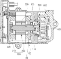
- FIG. 1 is a cross-sectional view illustrating a conventional scroll compressor.
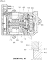
- FIG. 2 is an exploded perspective view illustrating a shaft and an eccentric bush in the scroll compressor of FIG. 1 .
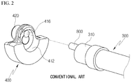
- FIG. 3 is a cross-sectional view illustrating a positional relationship between the shaft and the eccentric bush when the scroll compressor of FIG. 1 is normally operated.
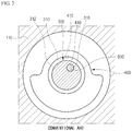
- FIG. 4 is a cross-sectional view illustrating a state in which the eccentric bush of FIG. 3 is rotated about the shaft by the rotational clearance therebetween.
- FIG. 5 is a cross-sectional view illustrating a state in which the eccentric bush of FIG. 4 is further rotated about the shaft by the rotational clearance therebetween.
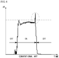
- FIG. 6 is a graph illustrating noise measured in the scroll compressor of FIG. 1 .
- the conventional scroll compressor includes a drive source 200 for generating a rotational force, a shaft 300 rotated by the drive source 200 , an eccentric bush 400 having a recess 410 , into which one end 310 of the shaft 300 is inserted, and an eccentric portion 420 eccentric to the shaft 300 , an orbiting scroll 500 that orbits while communicating with the eccentric portion 420 , and a fixed scroll 600 that defines a compression chamber together with the orbiting scroll 500 .
- the eccentric bush 400 is configured such that a rotational clearance is present between an inner peripheral surface 412 of the recess 410 and an outer peripheral surface 312 of the one end 310 of the shaft 300 , to prevent damage to the orbiting scroll 500 and the fixed scroll 600 due to liquid refrigerant compression, for example, as in initial operation. That is, the eccentric bush 400 is configured such that the rotational motion of the shaft 300 is not immediately transmitted to the eccentric bush 400 but is transmitted thereto in a buffered manner according to the designed rotational clearance.
- the eccentric bush 400 is rotated together with the shaft 300 in the state in which the recess 410 and the shaft 300 are concentric with each other, as illustrated in FIG. 3 .
- the eccentric bush 400 is rotated together with the shaft 300 in the state in which the eccentric bush 400 is rotated relative to the shaft 300 so that the radius of rotation of the eccentric bush 400 is adjusted, as illustrated in FIG. 4 .
- a scroll compressor that includes a rotating shaft, an eccentric bush having a recess, into which one end of the shaft is inserted, and an eccentric portion eccentric to the shaft, an orbiting scroll operatively connected to the eccentric portion for orbiting, a fixed scroll engaged with the orbiting scroll, and a buffer member interposed between the one end of the shaft and the recess.
- a buffer member's one end insertion groove may be formed on a tip surface of the one end of the shaft so that one end of the buffer member is inserted into the buffer member's one end insertion groove.
- a buffer member's other end insertion groove may be formed on a base surface of the recess facing the tip surface of the one end of the shaft so that the other end of the buffer member is inserted into the buffer member's other end insertion groove.
- a rotational clearance may be present between an inner peripheral surface of the recess and an outer peripheral surface of the one end of the shaft and between an inner peripheral surface of the buffer member's other end insertion groove and an outer peripheral surface of the other end of the buffer member.
- the rotational clearance may allow the outer peripheral surface of the other end of the buffer member to come into contact with the inner peripheral surface of the buffer member's other end insertion groove before the inner peripheral surface of the recess comes into contact with the outer peripheral surface of the one end of the shaft.
- a gap between the inner peripheral surface of the recess and the outer peripheral surface of the one end of the shaft may be constant, a gap between the inner peripheral surface of the buffer member's other end insertion groove and the outer peripheral surface of the other end of the buffer member may be constant, and the gap between the inner peripheral surface of the buffer member's other end insertion groove and the outer peripheral surface of the other end of the buffer member may be smaller than the gap between the inner peripheral surface of the recess and the outer peripheral surface of the one end of the shaft.
- the buffer member may be made of a material having a Shore hardness smaller than the buffer member's one end insertion groove and the buffer member's other end insertion groove.
- the gap between the inner peripheral surface of the buffer member's other end insertion groove and the outer peripheral surface of the other end of the buffer member may be formed in proportion to the Shore hardness of the buffer member.
- the gap between the inner peripheral surface of the buffer member's other end insertion groove and the outer peripheral surface of the other end of the buffer member is G 2 and the Shore hardness of the buffer member is H, they may be formed to satisfy a relation of 0 ⁇ G 2 ⁇ (0.02 mm/Shore hardness of 1 unit)*H ⁇ 1.2 mm.
- the buffer member may be made of a material having a Shore hardness of 70 units, and the gap between the inner peripheral surface of the buffer member's other end insertion groove and the outer peripheral surface of the other end of the buffer member may be greater than zero (0) and less than or equal to 0.2 mm.
- the buffer member may be made of a material having a Shore hardness of 80 units, and the gap between the inner peripheral surface of the buffer member's other end insertion groove and the outer peripheral surface of the other end of the buffer member may be greater than zero (0) and less than or equal to 0.4 mm.
- the inner peripheral surface of the buffer member's other end insertion groove may have a decreasing inner diameter in an axial direction from the tip surface of the one end of the shaft.
- a gap between the inner peripheral surface of the recess and the outer peripheral surface of the one end of the shaft may be constant
- a gap between the inner peripheral surface of the buffer member's other end insertion groove and the outer peripheral surface of the other end of the buffer member may be constant
- the minimum gap between the inner peripheral surface of the buffer member's other end insertion groove and the outer peripheral surface of the other end of the buffer member may be smaller than the gap between the inner peripheral surface of the recess and the outer peripheral surface of the one end of the shaft.
- the inner diameter of the inner peripheral surface of the buffer member's other end insertion groove may be linearly decreased in the axial direction from the tip surface of the one end of the shaft.
- a tip surface of the other end of the buffer member may be spaced apart from a base surface of the buffer member's other end insertion groove.
- a tip surface of the one end of the buffer member may be spaced apart from a base surface of the buffer member's one end insertion groove.
- At least one of an inner peripheral surface of the buffer member's one end insertion groove and an outer peripheral surface of the one end of the buffer member may have an irregularity formed thereon to prevent separation of the buffer member from the buffer member's one end insertion groove.
- the eccentric bush may further include a balance weight disposed on an opposite side of the eccentric portion with respect to the recess, a center of gravity of the balance weight may be formed on an opposite side of a center of the eccentric portion with respect to a center of the recess, and on an imaginary straight line connecting a center of the buffer member's other end insertion groove to the center of the recess and the center of gravity of the balance weight, the buffer member's other end insertion groove may be located between the center of the recess and the center of gravity of the balance weight.
- the buffer member's other end insertion groove may be formed symmetrically with respect to the center of the buffer member's other end insertion groove.
- the buffer member's one end insertion groove may face the buffer member's other end insertion groove and the buffer member's one end insertion groove may be formed symmetrically with respect to the center of the buffer member's one end insertion groove.
- FIG. 1 is a cross-sectional view illustrating a conventional scroll compressor
- FIG. 2 is an exploded perspective view illustrating a shaft and an eccentric bush in the scroll compressor of FIG. 1 ;
- FIG. 3 is a cross-sectional view illustrating a positional relationship between the shaft and the eccentric bush when the scroll compressor of FIG. 1 is normally operated;
- FIG. 4 is a cross-sectional view illustrating a state in which the eccentric bush of FIG. 3 is rotated about the shaft by the rotational clearance therebetween;
- FIG. 5 is a cross-sectional view illustrating a state in which the eccentric bush of FIG. 4 is further rotated about the shaft by the rotational clearance therebetween;
- FIG. 6 is a graph illustrating noise measured in the scroll compressor of FIG. 1 ;
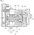
- FIG. 7 is a cross-sectional view illustrating a scroll compressor according to an embodiment of the present disclosure.
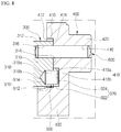
- FIG. 8 is an enlarged cross-sectional view illustrating a shaft, an eccentric bush, and a buffer member in the scroll compressor of FIG. 7 ;
- FIG. 9 is a cross-sectional view illustrating a positional relationship between the shaft, the eccentric bush, and the buffer member when the scroll compressor of FIG. 7 is normally operated;
- FIG. 10 is a cross-sectional view illustrating a state in which the eccentric bush of FIG. 9 is rotated about the shaft by the rotational clearance therebetween;
- FIG. 11 is a cross-sectional view illustrating a state in which the eccentric bush of FIG. 10 is further rotated about the shaft by the rotational clearance therebetween;
- FIG. 12 is a perspective view illustrating the buffer member of FIGS. 9 and 10 ;
- FIG. 13 is a perspective view illustrating the buffer member of FIG. 11 ;
- FIG. 14 is a graph illustrating noise measured in the scroll compressor of FIG. 7 ;
- FIG. 15 is a graph illustrating whether a collision noise is generated between the shaft and the eccentric bush when adjusting the material of the buffer member and the gap between the buffer member and the eccentric bush in the scroll compressor of FIG. 7 ;
- FIG. 16 is an enlarged cross-sectional view illustrating a shaft, an eccentric bush, and a buffer member in a scroll compressor according to another embodiment of the present disclosure
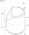
- FIG. 17 is a perspective view illustrating a state in which the buffer member is deformed by the eccentric bush in the scroll compressor of FIG. 16 ;
- FIGS. 18 to 20 are perspective views illustrating a buffer member in a scroll compressor according to a further embodiment of the present disclosure.
- FIG. 7 is a cross-sectional view illustrating a scroll compressor according to an embodiment of the present disclosure.
- FIG. 8 is an enlarged cross-sectional view illustrating a shaft, an eccentric bush, and a buffer member in the scroll compressor of FIG. 7 .
- FIG. 9 is a cross-sectional view illustrating a positional relationship between the shaft, the eccentric bush, and the buffer member when the scroll compressor of FIG. 7 is normally operated.
- FIG. 10 is a cross-sectional view illustrating a state in which the eccentric bush of FIG. 9 is rotated about the shaft by the rotational clearance therebetween.
- FIG. 11 is a cross-sectional view illustrating a state in which the eccentric bush of FIG. 10 is further rotated about the shaft by the rotational clearance therebetween.
- FIG. 12 is a perspective view illustrating the buffer member of FIGS. 9 and 10 .
- FIG. 13 is a perspective view illustrating the buffer member of FIG. 11 .
- FIG. 14 is a graph illustrating noise measured in the scroll compressor
- the scroll compressor may include a casing 100 , a drive source 200 provided in the casing 100 to generate a rotational force, a shaft 300 rotated by the drive source 200 , an eccentric bush 400 for converting the rotational motion of the shaft 300 into an eccentric rotational motion, a orbiting scroll 500 operatively connected to the eccentric bush 400 for orbiting, and a fixed scroll 600 engaged with the orbiting scroll 500 to define a compression chamber together with the orbiting scroll 500 .
- the casing 100 may include a main frame 110 supporting the orbiting scroll 500 .
- the main frame 110 may have a bearing hole 112 through which the shaft 300 passes.
- the bearing hole 112 may be formed with a bearing for rotatably supporting the shaft 300 .
- the main frame 110 may have an orbiting groove 114 in which the eccentric bush 400 orbits.
- the orbiting groove 114 may be recessed from one surface of the main frame 110 facing the orbiting scroll 500 and may communicate with the bearing hole 112 .
- the drive source 200 may be a motor having a stator 210 and a rotor 220 .
- the drive source 200 may also be formed as a disk hub assembly that is operatively connected to an engine of a vehicle.
- the shaft 300 may have a cylindrical shape and extend in one direction.
- the eccentric bush 400 may be coupled to one end 310 of the shaft 300 and the rotor 220 may be coupled to the other end 320 of the shaft 300 .
- the eccentric bush 400 may include a recess 410 into which the one end 310 of the shaft 300 is inserted, an eccentric portion 420 that protrudes to the opposite side of the one end 310 of the shaft 300 with respect to the recess 410 and is eccentric to the shaft 300 , and a balance weight 430 disposed on the opposite side of the eccentric portion 420 with respect to the recess 410 to balance the overall rotation of the eccentric bush 400 .
- the shaft 300 and the eccentric bush 400 may be configured such that a rotational clearance is present between an inner peripheral surface 412 of the recess 410 and an outer peripheral surface 312 of the one end 310 of the shaft 300 , to prevent damage to the scrolls due to liquid refrigerant compression, for example, as in initial operation.
- the shaft 300 and the eccentric bush 400 may be coupled to each other so that they are rotatable relative to each other with respect to a position eccentric from the axis of rotation of the shaft 300 .
- the one end 310 of the shaft 300 may be cylindrical in shape. That is, the outer peripheral surface 312 of the one end 310 of the shaft 300 may have a constant outer diameter, irrespective of the axial position of the shaft 300 .
- a hinge pin's one end insertion groove 316 may be formed on a tip surface 314 of the one end 310 of the shaft 300 so that one end of a hinge pin 800 for fastening the shaft 300 to the eccentric bush 400 is inserted into the hinge pin's one end insertion groove 316 .
- the center of the hinge pin's one end insertion groove 316 may be spaced apart from the axis of rotation of the shaft 300 in the radial direction of the shaft 300 such that the central axis of the hinge pin 800 is located at a position eccentric to the axis of rotation of the shaft 300 .
- the hinge pin 800 may have a cylindrical shape and extend in a direction parallel to the axial direction of the shaft 300 .
- the hinge pin's one end insertion groove 316 may be cylindrically recessed while having an inner diameter equal to the outer diameter of the hinge pin 800 so as to correspond to the hinge pin 800 .
- the recess 410 of the eccentric bush 400 may be cylindrically recessed corresponding to the one end 310 of the shaft 300 . That is, the inner peripheral surface 412 of the recess 410 may have a constant inner diameter, irrespective of the axial position of the recess 410 .
- the inner diameter of the recess 410 may be larger than the outer diameter of the one end 310 of the shaft 300 such that the eccentric bush 400 is rotatable relative to the shaft 300 about the hinge pin 800 . That is, a gap G 1 between the inner peripheral surface 412 of the recess 410 and the outer peripheral surface 312 of the one end 310 of the shaft 300 may be greater than zero (0).
- the gap G 1 between the inner peripheral surface 412 of the recess 410 and the outer peripheral surface 312 of the one end 310 of the shaft 300 is formed to be not less than a predetermined value so that the inner peripheral surface 412 of the recess 410 and the outer peripheral surface 312 of the one end 310 of the shaft 300 do not come into contact with each other, which will be described later.
- a hinge pin's other end insertion groove 416 may be formed on a base surface 414 of the recess 410 facing the tip surface 314 of the one end 310 of the shaft 300 so that the other end of the hinge pin 800 is inserted into the hinge pin's other end insertion groove 416 .
- the center of the hinge pin's other end insertion groove 416 may be spaced apart from the central axis of the recess 410 in the radial direction of the recess 410 such that the central axis of the hinge pin 800 is located at a position eccentric to the central axis of the recess 410 .
- the hinge pin's other end insertion groove 416 may be preferably formed at a position facing to the hinge pin's one end insertion groove 316 when the recess 410 is located at a position concentric with the one end 310 of the shaft 300 such that the eccentric bush 400 is rotatable relative to the shaft 300 in one direction and in a direction opposite thereto.
- the hinge pin's other end insertion groove 416 may be cylindrically recessed while having an inner diameter equal to the outer diameter of the hinge pin 800 so as to correspond to the hinge pin 800 .
- the scroll compressor according to the present embodiment may include a buffer member 900 interposed between the one end 310 of the shaft 300 and the recess 410 to prevent an impact sound from occurring by the eccentric bush 400 striking the shaft 300 due to the rotational clearance therebetween, for example, when rotation of the shaft 300 is interrupted.
- a buffer member's one end insertion groove 318 may be formed on the tip surface 314 of the one end 310 of the shaft 300 so that one end 910 of the buffer member 900 is inserted into the buffer member's one end insertion groove 318 .
- a buffer member's other end insertion groove 418 may be formed on the base surface 414 of the recess 410 so that the other end 920 of the buffer member 900 is inserted into the buffer member's other end insertion groove 418 .
- a rotational clearance may be present between an inner peripheral surface 418 a of the buffer member's other end insertion groove 418 and an outer peripheral surface 922 of the other end 920 of the buffer member 900 .
- the rotational clearance may allow the outer peripheral surface 922 of the other end 920 of the buffer member 900 to come into contact into the inner peripheral surface 418 a of the buffer member's other end insertion groove 418 before the inner peripheral surface 412 of the recess 410 comes into contact with the outer peripheral surface 312 of the one end 310 of the shaft 300 .
- the buffer member 900 may have a cylindrical shape and extend in one direction. That is, each of the outer peripheral surface 912 of the one end 910 of the buffer member 900 and the outer peripheral surface 922 of the other end 920 of the buffer member 900 may have a constant outer diameter, irrespective of the axial position of the buffer member 900 .
- the buffer member 900 may be made of a material (e.g., PTFE, plastic, or rubber) having an elastic modulus and Shore hardness smaller than the buffer member's one end insertion groove 318 and the buffer member's other end insertion groove 418 .
- a material e.g., PTFE, plastic, or rubber
- the outer peripheral surface 922 of the other end 920 of the buffer member 900 comes into contact with and is separated from the inner peripheral surface 418 a of the buffer member's other end insertion groove 418 depending on the position of the eccentric bush 400 relative to the shaft 300 in the state in which the one end 910 of the buffer member 900 is fastened to the buffer member's one end insertion groove 318 .
- the other end 920 of the buffer member 900 is deformed and restored while coming into contact with and being separated from the inner peripheral surface 418 a of the buffer member's other end insertion groove 418 .
- the buffer member's one end insertion groove 318 may be cylindrical in shape so as to correspond to the one end 910 of the buffer member 900 . That is, the inner peripheral surface 318 a of the buffer member's one end insertion groove 318 may have a constant inner diameter, irrespective of the axial position of the buffer member's one end insertion groove 318 .
- the inner diameter of the buffer member's one end insertion groove 318 may be smaller than the outer diameter of the one end 910 of the buffer member 900 such that the one end 910 of the buffer member 900 is press-fitted into the buffer member's one end insertion groove 318 .
- the buffer member's other end insertion groove 418 may be cylindrical in shape so as to correspond to the other end 920 of the buffer member 900 . That is, the inner peripheral surface 418 a of the buffer member's other end insertion groove 418 may have a constant inner diameter, irrespective of the axial position of the buffer member's other end insertion groove 418 .
- a rotational clearance may be present between the inner peripheral surface 418 a of the buffer member's other end insertion groove 418 and the outer peripheral surface 922 of the other end 920 of the buffer member 900 such that the outer peripheral surface 922 of the other end 920 of the buffer member 900 comes into contact with and is separated from the inner peripheral surface 418 a of the buffer member's other end insertion groove 418 depending on the position of the eccentric bush 400 relative to the shaft 300 .
- the inner diameter of the buffer member's other end insertion groove 418 may be larger than the outer diameter of the other end 920 of the buffer member 900 such that the other end 920 of the buffer member 900 is rotatable about the hinge pin 800 in the buffer member's other end insertion groove 418 . That is, a gap G 2 between the inner peripheral surface 418 a of the buffer member's other end insertion groove 418 and the outer peripheral surface 922 of the other end 920 of the buffer member 900 may be greater than zero (0).
- the gap G 2 between the inner peripheral surface 418 a of the buffer member's other end insertion groove 418 and the outer peripheral surface 922 of the other end 920 of the buffer member 900 may be formed to be smaller than a predetermined value so that the inner peripheral surface 412 of the recess 410 does not come into contact with the outer peripheral surface 312 of the one end 310 of the shaft 300 when the outer peripheral surface 922 of the other end 920 of the buffer member 900 comes into contact with the inner peripheral surface 418 a of the buffer member's other end insertion groove 418 .
- the gap G 1 between the inner peripheral surface 412 of the recess 410 and the outer peripheral surface 312 of the one end 310 of the shaft 300 is constant and the gap G 2 between the inner peripheral surface 418 a of the buffer member's other end insertion groove 418 and the outer peripheral surface 922 of the other end 920 of the buffer member 900 is constant, on a certain plane perpendicular to the one end 310 of the shaft 300 .
- the gap G 2 between the inner peripheral surface 418 a of the buffer member's other end insertion groove 418 and the outer peripheral surface 922 of the other end 920 of the buffer member 900 may be smaller than the gap G 1 between the inner peripheral surface 412 of the recess 410 and the outer peripheral surface 312 of the one end 310 of the shaft 300 .
- the rotational clearance is formed between the shaft 300 and the eccentric bush 400 (more exactly, between the outer peripheral surface 312 of the one end 310 of the shaft 300 and the inner peripheral surface 412 of the recess 410 ).
- the eccentric bush 400 is rotated together with the shaft 300 in the state in which the recess 410 and the shaft 300 are concentric with each other, as illustrated in FIG. 9 .
- the eccentric bush 400 may be rotated together with the shaft 300 in the state in which the eccentric bush 400 is rotated relative to the shaft 300 so that the radius of rotation of the eccentric bush 400 is adjusted, as illustrated in FIG. 10 . That is, the rotational motion of the shaft 300 is not be immediately transmitted to the eccentric bush 400 but is transmitted thereto in a buffered manner according to the designed rotational clearance. Therefore, it is possible to prevent damage to the scrolls due to liquid refrigerant compression.
- the buffer member 900 may be provided in such a manner that the one end 910 thereof is inserted into the buffer member's one end insertion groove 318 formed in the one end 310 of the shaft 300 and the other end 920 thereof is inserted into the buffer member's other end insertion groove 418 formed in the recess 410 .
- the one end 910 of the buffer member 900 may be fixed into the buffer member's one end insertion groove 318 and the other end 920 of the buffer member 900 may move in the buffer member's other end insertion groove 418 .
- the gap G 2 between the inner peripheral surface 418 a of the buffer member's other end insertion groove 418 and the outer peripheral surface 922 of the other end 920 of the buffer member 900 is smaller than the gap G 1 between the inner peripheral surface 412 of the recess 410 and the outer peripheral surface 312 of the one end 310 of the shaft 300 , with the consequence that it is possible to prevent an impact sound between the shaft 300 and the eccentric bush 400 .
- the other end 920 of the buffer member 900 restrains the rotation of the eccentric bush 400 , with the consequence that it is possible to prevent the inner peripheral surface 412 of the recess 410 from striking the outer peripheral surface 312 of the one end 310 of the shaft 300 , as illustrated in FIG. 11 . Therefore, as illustrated in FIG. 14 , it is possible to prevent an impact sound between the shaft 300 and the eccentric bush 400 and to improve the noise and vibration of the compressor.
- the buffer member is made of a material having an elastic modulus and Shore hardness smaller than the buffer member's one end insertion groove 318 and the buffer member's other end insertion groove 418 , it is possible to suppress noise and vibration due to the collision between the other end 920 of the buffer member 900 and the inner peripheral surface 418 a of the buffer member's other end insertion groove 418 and to prevent damage to the buffer member's one end insertion groove 318 and the buffer member's other end insertion groove 418 while the other end 920 of the buffer member 900 is deformed and restored, as illustrated in FIGS. 10 to 13 .
- the elastic modulus and Shore hardness of the buffer member 900 are too small, the noise and vibration of the compressor may not be improved.
- the other end 920 of the buffer member 900 may be relatively easily and greatly deformed when the eccentric bush 400 is further rotated relative to the shaft 300 from the state of FIG. 10 .
- the deformation and elastic restoring force of the buffer member 900 are proportional to each other. Therefore, as the deformation of the buffer member 900 increases, the force for restraining the rotation of the eccentric bush 400 increases. However, when the deformation of the buffer member 900 is insufficient and the elastic restoring force of the buffer member 900 is not enough to restrain the rotation of the eccentric bush 400 until the inner peripheral surface 412 of the recess 410 comes into contact with the outer peripheral surface of the shaft 300 , the inner peripheral surface 412 of the recess 410 may strike the outer peripheral surface 312 of the one end 310 of the shaft 300 .
- the elastic modulus and Shore hardness of the buffer member 900 are small, it is necessary to form the gap G 2 between the inner peripheral surface 418 a of the buffer member's other end insertion groove 418 and the outer peripheral surface 922 of the other end 920 of the buffer member 900 to be significantly smaller than the gap G 1 between the inner peripheral surface 412 of the recess 410 and the outer peripheral surface 312 of the one end 310 of the shaft 300 , such that the deformation of the buffer member 900 is sufficient and the elastic restoring force of the buffer member 900 is enough to restrain the rotation of the eccentric bush 400 before the inner peripheral surface 412 of the recess 410 comes into contact with the outer peripheral surface 312 of the one end 310 of the shaft 300 .
- the gap G 2 between the inner peripheral surface 418 a of the buffer member's other end insertion groove 418 and the outer peripheral surface 922 of the other end 920 of the buffer member 900 is necessary to form the gap G 2 between the inner peripheral surface 418 a of the buffer member's other end insertion groove 418 and the outer peripheral surface 922 of the other end 920 of the buffer member 900 to be proportional to the elastic modulus and the Shore hardness of the buffer member 900 .
- the material (Shore hardness) of the buffer member 900 and the gap G 2 between the inner peripheral surface 418 a of the buffer member's other end insertion groove 418 and the outer peripheral surface 922 of the other end 920 of the buffer member 900 must be formed to satisfy the first relation so that the collision noise between the shaft 300 and the eccentric bush 400 is not generated.
- the material (Shore hardness) of the buffer member 900 and the gap G 2 between the inner peripheral surface 418 a of the buffer member's other end insertion groove 418 and the outer peripheral surface 922 of the other end 920 of the buffer member 900 may be preferably formed to satisfy 0 ⁇ G 2 ⁇ (0.02 mm/Shore hardness of 1 unit)*H ⁇ 1.2 mm (hereinafter, referred to as a “second relation”).
- the buffer member 900 can more reliably restrain the rotation of the eccentric bush 400 .
- the material (Shore hardness) of the buffer member 900 and the gap G 2 between the inner peripheral surface 418 a of the buffer member's other end insertion groove 418 and the outer peripheral surface 922 of the other end 920 of the buffer member 900 are formed to satisfy the second relation, the effect of preventing damage to the scrolls due to liquid refrigerant compression may be deteriorated.
- the buffer member 900 may be preferably made of a material having a Shore hardness of 70 to 80 units.
- the buffer member 900 is made of a material having a Shore hardness of 70 units and the gap G 2 between the inner peripheral surface 418 a of the buffer member's other end insertion groove 418 and the outer peripheral surface 922 of the other end 920 of the buffer member 900 is 0.2 mm according to the third relation.
- the buffer member 900 is made of a material having a Shore hardness of 80 units and the gap G 2 between the inner peripheral surface 418 a of the buffer member's other end insertion groove 418 and the outer peripheral surface 922 of the other end 920 of the buffer member 900 is 0.4 mm according to the third relation.
- the buffer member 900 since the buffer member's other end insertion groove 418 has a cylindrical shape (since the inner peripheral surface 418 a of the buffer member's other end insertion groove 418 has a constant inner diameter, irrespective of the axial position of the buffer member's other end insertion groove 418 ), the buffer member 900 is deformed and restored as illustrated in FIGS. 12 and 13 . However, damage may occur between the one end 910 and the other end 920 of the buffer member 900 due to a considerable shear stress applied between the one end 910 and the other end 920 of the buffer member 900 .
- the buffer member's other end insertion groove 418 may have a conical shape as illustrated in FIG. 16 . That is, the inner peripheral surface 418 a of the buffer member's other end insertion groove 418 may have a decreasing inner diameter in the axial direction of the buffer member's other end insertion groove 418 from the tip surface 314 of the one end 310 of the shaft 300 .
- the inner diameter of the inner peripheral surface 418 a of the buffer member's other end insertion groove 418 is linearly decreased in the axial direction of the buffer member's other end insertion groove 418 from the tip surface 314 of the one end 310 of the shaft 300 .
- the shear stress applied the other end 920 of the buffer member 900 is evenly distributed.
- the gap G 2 between the inner peripheral surface 418 a of the buffer member's other end insertion groove 418 and the outer peripheral surface 922 of the other end 920 of the buffer member 900 varies depending on the axial position of the buffer member's other end insertion groove 418 .
- the minimum gap G 2 between the inner peripheral surface 418 a of the buffer member's other end insertion groove 418 and the outer peripheral surface 922 of the other end 920 of the buffer member 900 may be smaller than the gap G 1 between the inner peripheral surface 412 of the recess 410 and the outer peripheral surface 312 of the one end 310 of the shaft 300 .
- the gap G 2 between the inner peripheral surface 418 a of the buffer member's other end insertion groove 418 and the outer peripheral surface 922 of the other end 920 of the buffer member 900 may be smaller than the gap G 1 between the inner peripheral surface 412 of the recess 410 and the outer peripheral surface 312 of the one end 310 of the shaft 300 .
- the buffer member 900 interferes with the rotation of the eccentric bush 400 relative to the shaft 300 even though the inner peripheral surface 418 a of the buffer member's other end insertion groove 418 does not come into contact with the outer peripheral surface 922 of the other end 920 of the buffer member 900 .
- it is advantageous in terms of reducing the collision noise between the shaft 300 and the eccentric bush 400 , but it may be disadvantageous in terms of preventing damage to the scrolls due to liquid refrigerant compression.
- the tip surface 914 of the one end 910 of the buffer member 900 is spaced apart from the base surface 318 b of the buffer member's one end insertion groove 318 and the tip surface 924 of the other end 920 of the buffer member 900 is spaced apart from the base surface 418 b of the buffer member's other end insertion groove 418 , as illustrated in FIGS. 7 and 8 , such that the tip surface 924 of the other end 920 of the buffer member 900 does not come into contact with the base surface 418 b of the buffer member's other end insertion groove 418 not only when the compressor is stopped (before the thermal expansion of the buffer member 900 ) but also when the compressor is operated (after the thermal expansion of the buffer member 900 ).
- the tip surface 914 of the one end 910 of the buffer member 900 may come into contact with the base surface 318 b of the buffer member's one end insertion groove 318 and the tip surface 924 of the other end 920 of the buffer member 900 may be spaced apart from the base surface 418 b of the buffer member's other end insertion groove 418 .
- the tip surface 914 of the one end 910 of the buffer member 900 may be preferably spaced apart from the base surface 318 b of the buffer member's one end insertion groove 318 as in the present embodiment.
- each of the buffer member's one end insertion groove 318 and the one end 910 of the buffer member 900 has a cylindrical shape and the inner diameter of the one end 910 of the buffer member 900 is smaller than the outer diameter of the one end 910 of the buffer member 900 .
- the inner diameter of the buffer member's one end insertion groove 318 is equal to the outer diameter of the one end 910 of the buffer member and at least one of the inner peripheral surface 318 a of the buffer member's one end insertion groove 318 and the outer peripheral surface 912 of the one end 910 of the buffer member 900 has an irregularity U formed thereon.
- the irregularity U may be, for example, a protrusion protruding from the outer peripheral surface 912 of the one end 910 of the buffer member 900 .
- the irregularity U may be a plurality of protrusions arranged in the circumferential direction of the buffer member 900 .
- the irregularity U may be a single annular protrusion extending in the circumferential direction of the buffer member 900 .
- the irregularity U may be a plurality of annular protrusions arranged in the axial direction of the buffer member 900 .
- the buffer member's other end insertion groove 418 may be formed at any position in the region of the recess 410 . On the basis of when the recess 410 is located at a position concentric with the one end 310 of the shaft 300 , the buffer member's one end insertion groove 318 may be formed to face the buffer member's other end insertion groove 418 .
- the buffer member's other end insertion groove 418 may be preferably located between the center C 410 of the recess 410 and the center of gravity C 430 of the balance weight 430 as in the present embodiment.
- the buffer member's other end insertion groove 418 may be formed symmetrically with respect to the center C 418 of the buffer member's other end insertion groove 418 as in the present embodiment.
- the buffer member's one end insertion groove 318 faces the buffer member's other end insertion groove 418 and the buffer member's one end insertion groove 318 is formed symmetrically with respect to the center of the buffer member's one end insertion groove 318 while being concentric with the buffer member's other end insertion groove 418 .
Landscapes
- Engineering & Computer Science (AREA)
- Mechanical Engineering (AREA)
- General Engineering & Computer Science (AREA)
- Rotary Pumps (AREA)
- Applications Or Details Of Rotary Compressors (AREA)
Abstract
Description
- This patent application claims priority to Korean Patent Application No. 10-2018-0110154 filed Sep. 14, 2018, the entire disclosure of which is hereby incorporated herein by reference.
- Exemplary embodiments of the present disclosure relate to a scroll compressor, and more particularly, to a scroll compressor capable of compressing a refrigerant with a fixed scroll and an orbiting scroll.
- In general, a vehicle is equipped with an air conditioning (A/C) system for cooling/heating the interior thereof. This air conditioning system includes a compressor that is a component of a cooling system and compresses the low-temperature and low-pressure gas-phase refrigerant, introduced from an evaporator, to a high-temperature and high-pressure gas-phase refrigerant to send it to a condenser.
- Examples of the compressor include a reciprocating compressor that compresses a refrigerant according to which pistons reciprocate, and a rotary compressor that compresses a refrigerant while rotating. The reciprocating compressor includes a crank compressor that transmits a driving force from a drive source to a plurality of pistons using a crank, a swash plate compressor that transmits a driving force from a drive source to a shaft installed with a swash plate, and the like, according to the power transmission from the drive source. The rotary compressor includes a vane rotary compressor that utilizes a rotating rotary shaft and vane, and a scroll compressor that utilizes an orbiting scroll and a fixed scroll.
- The scroll compressor has been widely used for refrigerant compression in the air conditioning system or the like since the scroll compressor is advantageous in that it can obtain a relatively higher compression ratio and a more stable torque by smoothly performing the suction, compression, and discharge strokes of refrigerant, compared to other compressors.
-
FIG. 1 is a cross-sectional view illustrating a conventional scroll compressor.FIG. 2 is an exploded perspective view illustrating a shaft and an eccentric bush in the scroll compressor ofFIG. 1 .FIG. 3 is a cross-sectional view illustrating a positional relationship between the shaft and the eccentric bush when the scroll compressor ofFIG. 1 is normally operated.FIG. 4 is a cross-sectional view illustrating a state in which the eccentric bush ofFIG. 3 is rotated about the shaft by the rotational clearance therebetween.FIG. 5 is a cross-sectional view illustrating a state in which the eccentric bush ofFIG. 4 is further rotated about the shaft by the rotational clearance therebetween.FIG. 6 is a graph illustrating noise measured in the scroll compressor ofFIG. 1 . - Referring to
FIGS. 1 and 2 , the conventional scroll compressor includes adrive source 200 for generating a rotational force, ashaft 300 rotated by thedrive source 200, aneccentric bush 400 having arecess 410, into which oneend 310 of theshaft 300 is inserted, and aneccentric portion 420 eccentric to theshaft 300, an orbiting scroll 500 that orbits while communicating with theeccentric portion 420, and afixed scroll 600 that defines a compression chamber together with theorbiting scroll 500. - Here, the
eccentric bush 400 is configured such that a rotational clearance is present between an innerperipheral surface 412 of therecess 410 and an outerperipheral surface 312 of the oneend 310 of theshaft 300, to prevent damage to the orbitingscroll 500 and thefixed scroll 600 due to liquid refrigerant compression, for example, as in initial operation. That is, theeccentric bush 400 is configured such that the rotational motion of theshaft 300 is not immediately transmitted to theeccentric bush 400 but is transmitted thereto in a buffered manner according to the designed rotational clearance. Thus, when the scroll compressor is normally operated, theeccentric bush 400 is rotated together with theshaft 300 in the state in which therecess 410 and theshaft 300 are concentric with each other, as illustrated inFIG. 3 . However, for example, when the scroll compressor is initially operated, theeccentric bush 400 is rotated together with theshaft 300 in the state in which theeccentric bush 400 is rotated relative to theshaft 300 so that the radius of rotation of theeccentric bush 400 is adjusted, as illustrated inFIG. 4 . - However, in such a conventional scroll compressor, for example, when the rotational speed of the
shaft 300 is reduced or the rotation of theshaft 300 is interrupted, thebush 400 strikes theshaft 300 due to the rotational clearance as illustrated inFIG. 5 . Hence, as illustrated inFIG. 6 , an impact sound may occur and the noise and vibration of the compressor may be thus deteriorated. - Accordingly, it is an object of the present disclosure to provide a scroll compressor capable of providing a rotational clearance between a shaft and an eccentric bush to prevent damage to scrolls due to liquid refrigerant compression during initial operation and of preventing an impact sound between the shaft and the eccentric bush due to the rotational clearance.
- Other objects and advantages of the present disclosure can be understood by the following description, and become apparent with reference to the embodiments of the present disclosure. Also, it is obvious to those skilled in the art to which the present disclosure pertains that the objects and advantages of the present disclosure can be realized by the means as claimed and combinations thereof.
- In accordance with an aspect of the present disclosure, there is provided a scroll compressor that includes a rotating shaft, an eccentric bush having a recess, into which one end of the shaft is inserted, and an eccentric portion eccentric to the shaft, an orbiting scroll operatively connected to the eccentric portion for orbiting, a fixed scroll engaged with the orbiting scroll, and a buffer member interposed between the one end of the shaft and the recess.
- A buffer member's one end insertion groove may be formed on a tip surface of the one end of the shaft so that one end of the buffer member is inserted into the buffer member's one end insertion groove. A buffer member's other end insertion groove may be formed on a base surface of the recess facing the tip surface of the one end of the shaft so that the other end of the buffer member is inserted into the buffer member's other end insertion groove. A rotational clearance may be present between an inner peripheral surface of the recess and an outer peripheral surface of the one end of the shaft and between an inner peripheral surface of the buffer member's other end insertion groove and an outer peripheral surface of the other end of the buffer member. The rotational clearance may allow the outer peripheral surface of the other end of the buffer member to come into contact with the inner peripheral surface of the buffer member's other end insertion groove before the inner peripheral surface of the recess comes into contact with the outer peripheral surface of the one end of the shaft.
- When the recess is located at a position concentric with the one end of the shaft, a gap between the inner peripheral surface of the recess and the outer peripheral surface of the one end of the shaft may be constant, a gap between the inner peripheral surface of the buffer member's other end insertion groove and the outer peripheral surface of the other end of the buffer member may be constant, and the gap between the inner peripheral surface of the buffer member's other end insertion groove and the outer peripheral surface of the other end of the buffer member may be smaller than the gap between the inner peripheral surface of the recess and the outer peripheral surface of the one end of the shaft.
- The buffer member may be made of a material having a Shore hardness smaller than the buffer member's one end insertion groove and the buffer member's other end insertion groove.
- The gap between the inner peripheral surface of the buffer member's other end insertion groove and the outer peripheral surface of the other end of the buffer member may be formed in proportion to the Shore hardness of the buffer member.
- When assuming that the gap between the inner peripheral surface of the buffer member's other end insertion groove and the outer peripheral surface of the other end of the buffer member is G2 and the Shore hardness of the buffer member is H, they may be formed to satisfy a relation of 0<G2≤(0.02 mm/Shore hardness of 1 unit)*H−1.2 mm.
- The buffer member may be made of a material having a Shore hardness of 70 units, and the gap between the inner peripheral surface of the buffer member's other end insertion groove and the outer peripheral surface of the other end of the buffer member may be greater than zero (0) and less than or equal to 0.2 mm.
- The buffer member may be made of a material having a Shore hardness of 80 units, and the gap between the inner peripheral surface of the buffer member's other end insertion groove and the outer peripheral surface of the other end of the buffer member may be greater than zero (0) and less than or equal to 0.4 mm.
- The inner peripheral surface of the buffer member's other end insertion groove may have a decreasing inner diameter in an axial direction from the tip surface of the one end of the shaft. When the recess is located at a position concentric with the one end of the shaft, a gap between the inner peripheral surface of the recess and the outer peripheral surface of the one end of the shaft may be constant, a gap between the inner peripheral surface of the buffer member's other end insertion groove and the outer peripheral surface of the other end of the buffer member may be constant, and the minimum gap between the inner peripheral surface of the buffer member's other end insertion groove and the outer peripheral surface of the other end of the buffer member may be smaller than the gap between the inner peripheral surface of the recess and the outer peripheral surface of the one end of the shaft.
- The inner diameter of the inner peripheral surface of the buffer member's other end insertion groove may be linearly decreased in the axial direction from the tip surface of the one end of the shaft.
- A tip surface of the other end of the buffer member may be spaced apart from a base surface of the buffer member's other end insertion groove.
- A tip surface of the one end of the buffer member may be spaced apart from a base surface of the buffer member's one end insertion groove.
- At least one of an inner peripheral surface of the buffer member's one end insertion groove and an outer peripheral surface of the one end of the buffer member may have an irregularity formed thereon to prevent separation of the buffer member from the buffer member's one end insertion groove.
- The eccentric bush may further include a balance weight disposed on an opposite side of the eccentric portion with respect to the recess, a center of gravity of the balance weight may be formed on an opposite side of a center of the eccentric portion with respect to a center of the recess, and on an imaginary straight line connecting a center of the buffer member's other end insertion groove to the center of the recess and the center of gravity of the balance weight, the buffer member's other end insertion groove may be located between the center of the recess and the center of gravity of the balance weight.
- The buffer member's other end insertion groove may be formed symmetrically with respect to the center of the buffer member's other end insertion groove.
- When the recess is located at a position concentric with the one end of the shaft, the buffer member's one end insertion groove may face the buffer member's other end insertion groove and the buffer member's one end insertion groove may be formed symmetrically with respect to the center of the buffer member's one end insertion groove.
- It is to be understood that both the foregoing general description and the following detailed description of the present disclosure are exemplary and explanatory and are intended to provide further explanation of the disclosure as claimed.
- The above and other objects, features and other advantages of the present disclosure will be more clearly understood from the following detailed description taken in conjunction with the accompanying drawings, in which:
-
FIG. 1 is a cross-sectional view illustrating a conventional scroll compressor; -
FIG. 2 is an exploded perspective view illustrating a shaft and an eccentric bush in the scroll compressor ofFIG. 1 ; -
FIG. 3 is a cross-sectional view illustrating a positional relationship between the shaft and the eccentric bush when the scroll compressor ofFIG. 1 is normally operated; -
FIG. 4 is a cross-sectional view illustrating a state in which the eccentric bush ofFIG. 3 is rotated about the shaft by the rotational clearance therebetween; -
FIG. 5 is a cross-sectional view illustrating a state in which the eccentric bush ofFIG. 4 is further rotated about the shaft by the rotational clearance therebetween; -
FIG. 6 is a graph illustrating noise measured in the scroll compressor ofFIG. 1 ; -
FIG. 7 is a cross-sectional view illustrating a scroll compressor according to an embodiment of the present disclosure; -
FIG. 8 is an enlarged cross-sectional view illustrating a shaft, an eccentric bush, and a buffer member in the scroll compressor ofFIG. 7 ; -
FIG. 9 is a cross-sectional view illustrating a positional relationship between the shaft, the eccentric bush, and the buffer member when the scroll compressor ofFIG. 7 is normally operated; -
FIG. 10 is a cross-sectional view illustrating a state in which the eccentric bush ofFIG. 9 is rotated about the shaft by the rotational clearance therebetween; -
FIG. 11 is a cross-sectional view illustrating a state in which the eccentric bush ofFIG. 10 is further rotated about the shaft by the rotational clearance therebetween; -
FIG. 12 is a perspective view illustrating the buffer member ofFIGS. 9 and 10 ; -
FIG. 13 is a perspective view illustrating the buffer member ofFIG. 11 ; -
FIG. 14 is a graph illustrating noise measured in the scroll compressor ofFIG. 7 ; -
FIG. 15 is a graph illustrating whether a collision noise is generated between the shaft and the eccentric bush when adjusting the material of the buffer member and the gap between the buffer member and the eccentric bush in the scroll compressor ofFIG. 7 ; -
FIG. 16 is an enlarged cross-sectional view illustrating a shaft, an eccentric bush, and a buffer member in a scroll compressor according to another embodiment of the present disclosure; -
FIG. 17 is a perspective view illustrating a state in which the buffer member is deformed by the eccentric bush in the scroll compressor ofFIG. 16 ; and -
FIGS. 18 to 20 are perspective views illustrating a buffer member in a scroll compressor according to a further embodiment of the present disclosure. - Hereinafter, a scroll compressor according to exemplary embodiments of the present disclosure will be described in detail with reference to the accompanying drawings.
-
FIG. 7 is a cross-sectional view illustrating a scroll compressor according to an embodiment of the present disclosure.FIG. 8 is an enlarged cross-sectional view illustrating a shaft, an eccentric bush, and a buffer member in the scroll compressor ofFIG. 7 .FIG. 9 is a cross-sectional view illustrating a positional relationship between the shaft, the eccentric bush, and the buffer member when the scroll compressor ofFIG. 7 is normally operated.FIG. 10 is a cross-sectional view illustrating a state in which the eccentric bush ofFIG. 9 is rotated about the shaft by the rotational clearance therebetween.FIG. 11 is a cross-sectional view illustrating a state in which the eccentric bush ofFIG. 10 is further rotated about the shaft by the rotational clearance therebetween.FIG. 12 is a perspective view illustrating the buffer member ofFIGS. 9 and 10 .FIG. 13 is a perspective view illustrating the buffer member ofFIG. 11 .FIG. 14 is a graph illustrating noise measured in the scroll compressor ofFIG. 7 . - Referring to
FIGS. 7 to 14 , the scroll compressor according to the embodiment of the present disclosure may include acasing 100, adrive source 200 provided in thecasing 100 to generate a rotational force, ashaft 300 rotated by thedrive source 200, aneccentric bush 400 for converting the rotational motion of theshaft 300 into an eccentric rotational motion, aorbiting scroll 500 operatively connected to theeccentric bush 400 for orbiting, and afixed scroll 600 engaged with theorbiting scroll 500 to define a compression chamber together with theorbiting scroll 500. - The
casing 100 may include amain frame 110 supporting theorbiting scroll 500. - The
main frame 110 may have abearing hole 112 through which theshaft 300 passes. - The
bearing hole 112 may be formed with a bearing for rotatably supporting theshaft 300. - The
main frame 110 may have an orbiting groove 114 in which theeccentric bush 400 orbits. - The orbiting groove 114 may be recessed from one surface of the
main frame 110 facing theorbiting scroll 500 and may communicate with thebearing hole 112. - The
drive source 200 may be a motor having astator 210 and arotor 220. Thedrive source 200 may also be formed as a disk hub assembly that is operatively connected to an engine of a vehicle. - The
shaft 300 may have a cylindrical shape and extend in one direction. Theeccentric bush 400 may be coupled to oneend 310 of theshaft 300 and therotor 220 may be coupled to theother end 320 of theshaft 300. - The
eccentric bush 400 may include arecess 410 into which the oneend 310 of theshaft 300 is inserted, aneccentric portion 420 that protrudes to the opposite side of the oneend 310 of theshaft 300 with respect to therecess 410 and is eccentric to theshaft 300, and abalance weight 430 disposed on the opposite side of theeccentric portion 420 with respect to therecess 410 to balance the overall rotation of theeccentric bush 400. - The
shaft 300 and theeccentric bush 400 may be configured such that a rotational clearance is present between an innerperipheral surface 412 of therecess 410 and an outerperipheral surface 312 of the oneend 310 of theshaft 300, to prevent damage to the scrolls due to liquid refrigerant compression, for example, as in initial operation. - That is, the
shaft 300 and theeccentric bush 400 may be coupled to each other so that they are rotatable relative to each other with respect to a position eccentric from the axis of rotation of theshaft 300. - Specifically, the one
end 310 of theshaft 300 may be cylindrical in shape. That is, the outerperipheral surface 312 of the oneend 310 of theshaft 300 may have a constant outer diameter, irrespective of the axial position of theshaft 300. - A hinge pin's one
end insertion groove 316 may be formed on atip surface 314 of the oneend 310 of theshaft 300 so that one end of ahinge pin 800 for fastening theshaft 300 to theeccentric bush 400 is inserted into the hinge pin's oneend insertion groove 316. - The center of the hinge pin's one
end insertion groove 316 may be spaced apart from the axis of rotation of theshaft 300 in the radial direction of theshaft 300 such that the central axis of thehinge pin 800 is located at a position eccentric to the axis of rotation of theshaft 300. - The
hinge pin 800 may have a cylindrical shape and extend in a direction parallel to the axial direction of theshaft 300. The hinge pin's oneend insertion groove 316 may be cylindrically recessed while having an inner diameter equal to the outer diameter of thehinge pin 800 so as to correspond to thehinge pin 800. - The
recess 410 of theeccentric bush 400 may be cylindrically recessed corresponding to the oneend 310 of theshaft 300. That is, the innerperipheral surface 412 of therecess 410 may have a constant inner diameter, irrespective of the axial position of therecess 410. - The inner diameter of the
recess 410 may be larger than the outer diameter of the oneend 310 of theshaft 300 such that theeccentric bush 400 is rotatable relative to theshaft 300 about thehinge pin 800. That is, a gap G1 between the innerperipheral surface 412 of therecess 410 and the outerperipheral surface 312 of the oneend 310 of theshaft 300 may be greater than zero (0). Here, the gap G1 between the innerperipheral surface 412 of therecess 410 and the outerperipheral surface 312 of the oneend 310 of theshaft 300 is formed to be not less than a predetermined value so that the innerperipheral surface 412 of therecess 410 and the outerperipheral surface 312 of the oneend 310 of theshaft 300 do not come into contact with each other, which will be described later. - A hinge pin's other
end insertion groove 416 may be formed on abase surface 414 of therecess 410 facing thetip surface 314 of the oneend 310 of theshaft 300 so that the other end of thehinge pin 800 is inserted into the hinge pin's otherend insertion groove 416. - The center of the hinge pin's other
end insertion groove 416 may be spaced apart from the central axis of therecess 410 in the radial direction of therecess 410 such that the central axis of thehinge pin 800 is located at a position eccentric to the central axis of therecess 410. The hinge pin's otherend insertion groove 416 may be preferably formed at a position facing to the hinge pin's oneend insertion groove 316 when therecess 410 is located at a position concentric with the oneend 310 of theshaft 300 such that theeccentric bush 400 is rotatable relative to theshaft 300 in one direction and in a direction opposite thereto. - The hinge pin's other
end insertion groove 416 may be cylindrically recessed while having an inner diameter equal to the outer diameter of thehinge pin 800 so as to correspond to thehinge pin 800. - Meanwhile, the scroll compressor according to the present embodiment may include a
buffer member 900 interposed between the oneend 310 of theshaft 300 and therecess 410 to prevent an impact sound from occurring by theeccentric bush 400 striking theshaft 300 due to the rotational clearance therebetween, for example, when rotation of theshaft 300 is interrupted. A buffer member's oneend insertion groove 318 may be formed on thetip surface 314 of the oneend 310 of theshaft 300 so that oneend 910 of thebuffer member 900 is inserted into the buffer member's oneend insertion groove 318. A buffer member's otherend insertion groove 418 may be formed on thebase surface 414 of therecess 410 so that theother end 920 of thebuffer member 900 is inserted into the buffer member's otherend insertion groove 418. A rotational clearance may be present between an innerperipheral surface 418 a of the buffer member's otherend insertion groove 418 and an outerperipheral surface 922 of theother end 920 of thebuffer member 900. The rotational clearance may allow the outerperipheral surface 922 of theother end 920 of thebuffer member 900 to come into contact into the innerperipheral surface 418 a of the buffer member's otherend insertion groove 418 before the innerperipheral surface 412 of therecess 410 comes into contact with the outerperipheral surface 312 of the oneend 310 of theshaft 300. - Specifically, the
buffer member 900 may have a cylindrical shape and extend in one direction. That is, each of the outerperipheral surface 912 of the oneend 910 of thebuffer member 900 and the outerperipheral surface 922 of theother end 920 of thebuffer member 900 may have a constant outer diameter, irrespective of the axial position of thebuffer member 900. - The
buffer member 900 may be made of a material (e.g., PTFE, plastic, or rubber) having an elastic modulus and Shore hardness smaller than the buffer member's oneend insertion groove 318 and the buffer member's otherend insertion groove 418. Thus, the outerperipheral surface 922 of theother end 920 of thebuffer member 900 comes into contact with and is separated from the innerperipheral surface 418 a of the buffer member's otherend insertion groove 418 depending on the position of theeccentric bush 400 relative to theshaft 300 in the state in which the oneend 910 of thebuffer member 900 is fastened to the buffer member's oneend insertion groove 318. In addition, theother end 920 of thebuffer member 900 is deformed and restored while coming into contact with and being separated from the innerperipheral surface 418 a of the buffer member's otherend insertion groove 418. - The buffer member's one
end insertion groove 318 may be cylindrical in shape so as to correspond to the oneend 910 of thebuffer member 900. That is, the innerperipheral surface 318 a of the buffer member's oneend insertion groove 318 may have a constant inner diameter, irrespective of the axial position of the buffer member's oneend insertion groove 318. - The inner diameter of the buffer member's one
end insertion groove 318 may be smaller than the outer diameter of the oneend 910 of thebuffer member 900 such that the oneend 910 of thebuffer member 900 is press-fitted into the buffer member's oneend insertion groove 318. - The buffer member's other
end insertion groove 418 may be cylindrical in shape so as to correspond to theother end 920 of thebuffer member 900. That is, the innerperipheral surface 418 a of the buffer member's otherend insertion groove 418 may have a constant inner diameter, irrespective of the axial position of the buffer member's otherend insertion groove 418. - A rotational clearance may be present between the inner
peripheral surface 418 a of the buffer member's otherend insertion groove 418 and the outerperipheral surface 922 of theother end 920 of thebuffer member 900 such that the outerperipheral surface 922 of theother end 920 of thebuffer member 900 comes into contact with and is separated from the innerperipheral surface 418 a of the buffer member's otherend insertion groove 418 depending on the position of theeccentric bush 400 relative to theshaft 300. In other words, the inner diameter of the buffer member's otherend insertion groove 418 may be larger than the outer diameter of theother end 920 of thebuffer member 900 such that theother end 920 of thebuffer member 900 is rotatable about thehinge pin 800 in the buffer member's otherend insertion groove 418. That is, a gap G2 between the innerperipheral surface 418 a of the buffer member's otherend insertion groove 418 and the outerperipheral surface 922 of theother end 920 of thebuffer member 900 may be greater than zero (0). - The gap G2 between the inner
peripheral surface 418 a of the buffer member's otherend insertion groove 418 and the outerperipheral surface 922 of theother end 920 of thebuffer member 900 may be formed to be smaller than a predetermined value so that the innerperipheral surface 412 of therecess 410 does not come into contact with the outerperipheral surface 312 of the oneend 310 of theshaft 300 when the outerperipheral surface 922 of theother end 920 of thebuffer member 900 comes into contact with the innerperipheral surface 418 a of the buffer member's otherend insertion groove 418. That is, on the basis of when therecess 410 is located at a position concentric with the oneend 310 of theshaft 300, the gap G1 between the innerperipheral surface 412 of therecess 410 and the outerperipheral surface 312 of the oneend 310 of theshaft 300 is constant and the gap G2 between the innerperipheral surface 418 a of the buffer member's otherend insertion groove 418 and the outerperipheral surface 922 of theother end 920 of thebuffer member 900 is constant, on a certain plane perpendicular to the oneend 310 of theshaft 300. In this case, the gap G2 between the innerperipheral surface 418 a of the buffer member's otherend insertion groove 418 and the outerperipheral surface 922 of theother end 920 of thebuffer member 900 may be smaller than the gap G1 between the innerperipheral surface 412 of therecess 410 and the outerperipheral surface 312 of the oneend 310 of theshaft 300. - Hereinafter, the operation and effect of the scroll compressor according to the present embodiment will be described.
- When electric power is applied to the
drive source 200, a series of processes may be repeated in which theshaft 300 is rotated together with therotor 220, theorbiting scroll 500 is operatively connected to theshaft 300 through theeccentric bush 400 for orbiting, and a refrigerant is sucked into the compression chamber by the orbiting of theorbiting scroll 500, compressed in the compression chamber, and discharged from the compression chamber. - In the scroll compressor according to the present embodiment, the rotational clearance is formed between the
shaft 300 and the eccentric bush 400 (more exactly, between the outerperipheral surface 312 of the oneend 310 of theshaft 300 and the innerperipheral surface 412 of the recess 410). Thus, when the scroll compressor is normally operated, theeccentric bush 400 is rotated together with theshaft 300 in the state in which therecess 410 and theshaft 300 are concentric with each other, as illustrated inFIG. 9 . However, for example, when a liquid refrigerant is present as in initial operation, theeccentric bush 400 may be rotated together with theshaft 300 in the state in which theeccentric bush 400 is rotated relative to theshaft 300 so that the radius of rotation of theeccentric bush 400 is adjusted, as illustrated inFIG. 10 . That is, the rotational motion of theshaft 300 is not be immediately transmitted to theeccentric bush 400 but is transmitted thereto in a buffered manner according to the designed rotational clearance. Therefore, it is possible to prevent damage to the scrolls due to liquid refrigerant compression. - The
buffer member 900 may be provided in such a manner that the oneend 910 thereof is inserted into the buffer member's oneend insertion groove 318 formed in the oneend 310 of theshaft 300 and theother end 920 thereof is inserted into the buffer member's otherend insertion groove 418 formed in therecess 410. The oneend 910 of thebuffer member 900 may be fixed into the buffer member's oneend insertion groove 318 and theother end 920 of thebuffer member 900 may move in the buffer member's otherend insertion groove 418. On the basis of when therecess 410 is located at a position concentric with the oneend 310 of theshaft 300, the gap G2 between the innerperipheral surface 418 a of the buffer member's otherend insertion groove 418 and the outerperipheral surface 922 of theother end 920 of thebuffer member 900 is smaller than the gap G1 between the innerperipheral surface 412 of therecess 410 and the outerperipheral surface 312 of the oneend 310 of theshaft 300, with the consequence that it is possible to prevent an impact sound between theshaft 300 and theeccentric bush 400. That is, when theeccentric bush 400 is rotated relative to theshaft 300, the innerperipheral surface 418 a of the buffer member's otherend insertion groove 418 comes into contact with the outerperipheral surface 922 of theother end 920 of thebuffer member 900 before the innerperipheral surface 412 of therecess 410 comes into contact with the outerperipheral surface 312 of the oneend 310 of theshaft 300, as illustrated inFIG. 10 . When theeccentric bush 400 is further rotated relative to theshaft 300 from the state ofFIG. 10 , theother end 920 of thebuffer member 900 restrains the rotation of theeccentric bush 400, with the consequence that it is possible to prevent the innerperipheral surface 412 of therecess 410 from striking the outerperipheral surface 312 of the oneend 310 of theshaft 300, as illustrated inFIG. 11 . Therefore, as illustrated inFIG. 14 , it is possible to prevent an impact sound between theshaft 300 and theeccentric bush 400 and to improve the noise and vibration of the compressor. - Since the buffer member is made of a material having an elastic modulus and Shore hardness smaller than the buffer member's one
end insertion groove 318 and the buffer member's otherend insertion groove 418, it is possible to suppress noise and vibration due to the collision between theother end 920 of thebuffer member 900 and the innerperipheral surface 418 a of the buffer member's otherend insertion groove 418 and to prevent damage to the buffer member's oneend insertion groove 318 and the buffer member's otherend insertion groove 418 while theother end 920 of thebuffer member 900 is deformed and restored, as illustrated inFIGS. 10 to 13 . - Meanwhile, if the elastic modulus and Shore hardness of the
buffer member 900 are too small, the noise and vibration of the compressor may not be improved. - Specifically, if the elastic modulus and Shore hardness of the
buffer member 900 are small, theother end 920 of thebuffer member 900 may be relatively easily and greatly deformed when theeccentric bush 400 is further rotated relative to theshaft 300 from the state ofFIG. 10 . - Of course, the deformation and elastic restoring force of the
buffer member 900 are proportional to each other. Therefore, as the deformation of thebuffer member 900 increases, the force for restraining the rotation of theeccentric bush 400 increases. However, when the deformation of thebuffer member 900 is insufficient and the elastic restoring force of thebuffer member 900 is not enough to restrain the rotation of theeccentric bush 400 until the innerperipheral surface 412 of therecess 410 comes into contact with the outer peripheral surface of theshaft 300, the innerperipheral surface 412 of therecess 410 may strike the outerperipheral surface 312 of the oneend 310 of theshaft 300. - In this regard, if the elastic modulus and Shore hardness of the
buffer member 900 are small, it is necessary to form the gap G2 between the innerperipheral surface 418 a of the buffer member's otherend insertion groove 418 and the outerperipheral surface 922 of theother end 920 of thebuffer member 900 to be significantly smaller than the gap G1 between the innerperipheral surface 412 of therecess 410 and the outerperipheral surface 312 of the oneend 310 of theshaft 300, such that the deformation of thebuffer member 900 is sufficient and the elastic restoring force of thebuffer member 900 is enough to restrain the rotation of theeccentric bush 400 before the innerperipheral surface 412 of therecess 410 comes into contact with the outerperipheral surface 312 of the oneend 310 of theshaft 300. That is, it is necessary to form the gap G2 between the innerperipheral surface 418 a of the buffer member's otherend insertion groove 418 and the outerperipheral surface 922 of theother end 920 of thebuffer member 900 to be proportional to the elastic modulus and the Shore hardness of thebuffer member 900. - More specifically, referring to
FIG. 15 , it is tested whether a collision noise is generated between theshaft 300 and theeccentric bush 400 while adjusting the material (Shore hardness) of thebuffer member 900 and the gap G2 between the innerperipheral surface 418 a of the buffer member's otherend insertion groove 418 and the outerperipheral surface 922 of theother end 920 of thebuffer member 900. As a result, when 0<G2≤(0.02 mm/Shore hardness of 1 unit)*H−1.2 mm (hereinafter, referred to as a “first relation”) is satisfied, it is determined that the collision noise between theshaft 300 and theeccentric bush 400 is not generated. Here, reference character H refers to the Shore hardness of thebuffer member 900. - Accordingly, the material (Shore hardness) of the
buffer member 900 and the gap G2 between the innerperipheral surface 418 a of the buffer member's otherend insertion groove 418 and the outerperipheral surface 922 of theother end 920 of thebuffer member 900 must be formed to satisfy the first relation so that the collision noise between theshaft 300 and theeccentric bush 400 is not generated. - In terms of preventing the collision noise between the
shaft 300 and theeccentric bush 400, the material (Shore hardness) of thebuffer member 900 and the gap G2 between the innerperipheral surface 418 a of the buffer member's otherend insertion groove 418 and the outerperipheral surface 922 of theother end 920 of thebuffer member 900 may be preferably formed to satisfy 0<G2<(0.02 mm/Shore hardness of 1 unit)*H−1.2 mm (hereinafter, referred to as a “second relation”). That is, when the second relation is satisfied (when the gap G2 between the innerperipheral surface 418 a of the buffer member's otherend insertion groove 418 and the outerperipheral surface 922 of theother end 920 of thebuffer member 900 is very small), the deformation of theother end 920 of thebuffer member 900 increases under the same condition. Therefore, thebuffer member 900 can more reliably restrain the rotation of theeccentric bush 400. - However, the material (Shore hardness) of the
buffer member 900 and the gap G2 between the innerperipheral surface 418 a of the buffer member's otherend insertion groove 418 and the outerperipheral surface 922 of theother end 920 of thebuffer member 900 are formed to satisfy the second relation, the effect of preventing damage to the scrolls due to liquid refrigerant compression may be deteriorated. That is, it is easy to rotate theeccentric bush 400 relative to theshaft 300 only until the innerperipheral surface 418 a of the buffer member's otherend insertion groove 418 comes into contact with the outerperipheral surface 922 of theother end 920 of thebuffer member 900, whereas it is difficult to rotate theeccentric bush 400 relative to theshaft 300 after the innerperipheral surface 418 a of the buffer member's otherend insertion groove 418 comes into contact with the outerperipheral surface 922 of theother end 920 of thebuffer member 900. Hence, after the innerperipheral surface 418 a of the buffer member's otherend insertion groove 418 comes into contact with the outerperipheral surface 922 of theother end 920 of thebuffer member 900, the effect of preventing damage to the scrolls due to liquid refrigerant compression may be deteriorated. - In this regard, the material (Shore hardness) of the
buffer member 900 and the gap G2 between the innerperipheral surface 418 a of the buffer member's otherend insertion groove 418 and the outerperipheral surface 922 of theother end 920 of thebuffer member 900 may be preferably formed to satisfy 0<G2=(0.02 mm/Shore hardness of 1 unit)*H−1.2 mm (hereinafter, referred to as a “third relation”). Thus, it is possible to prevent the collision noise between theshaft 300 and theeccentric bush 400 and to reduce the deterioration of the effect of preventing damage to the scrolls due to liquid refrigerant compression. - Meanwhile, when comprehensively considering the durability performance of the
shaft 300, theeccentric bush 400, and thebuffer member 900 or the like, thebuffer member 900 may be preferably made of a material having a Shore hardness of 70 to 80 units. - Accordingly, comprehensively considering the above-mentioned features, it may be preferred that the
buffer member 900 is made of a material having a Shore hardness of 70 units and the gap G2 between the innerperipheral surface 418 a of the buffer member's otherend insertion groove 418 and the outerperipheral surface 922 of theother end 920 of thebuffer member 900 is 0.2 mm according to the third relation. - In addition, it may be preferred that the
buffer member 900 is made of a material having a Shore hardness of 80 units and the gap G2 between the innerperipheral surface 418 a of the buffer member's otherend insertion groove 418 and the outerperipheral surface 922 of theother end 920 of thebuffer member 900 is 0.4 mm according to the third relation. - In the present embodiment, since the buffer member's other
end insertion groove 418 has a cylindrical shape (since the innerperipheral surface 418 a of the buffer member's otherend insertion groove 418 has a constant inner diameter, irrespective of the axial position of the buffer member's other end insertion groove 418), thebuffer member 900 is deformed and restored as illustrated inFIGS. 12 and 13 . However, damage may occur between the oneend 910 and theother end 920 of thebuffer member 900 due to a considerable shear stress applied between the oneend 910 and theother end 920 of thebuffer member 900. - In this regard, the buffer member's other
end insertion groove 418 may have a conical shape as illustrated inFIG. 16 . That is, the innerperipheral surface 418 a of the buffer member's otherend insertion groove 418 may have a decreasing inner diameter in the axial direction of the buffer member's otherend insertion groove 418 from thetip surface 314 of the oneend 310 of theshaft 300. - In this case, it may be preferable that the inner diameter of the inner
peripheral surface 418 a of the buffer member's otherend insertion groove 418 is linearly decreased in the axial direction of the buffer member's otherend insertion groove 418 from thetip surface 314 of the oneend 310 of theshaft 300. Thus, the shear stress applied theother end 920 of thebuffer member 900 is evenly distributed. - When the
other end 920 of thebuffer member 900 is pressed into the buffer member's otherend insertion groove 418, it is deformed as illustrated inFIG. 17 so that the shear stress applied theother end 920 of thebuffer member 900 is reduced. Therefore, it is possible to suppress damage between the oneend 910 and theother end 920 of thebuffer member 900. - In the embodiment illustrated in
FIGS. 16 and 17 , the gap G2 between the innerperipheral surface 418 a of the buffer member's otherend insertion groove 418 and the outerperipheral surface 922 of theother end 920 of thebuffer member 900 varies depending on the axial position of the buffer member's otherend insertion groove 418. In order to prevent the collision noise between theshaft 300 and theeccentric bush 400, on the basis of when therecess 410 is located at a position concentric with the oneend 310 of theshaft 300, the minimum gap G2 between the innerperipheral surface 418 a of the buffer member's otherend insertion groove 418 and the outerperipheral surface 922 of theother end 920 of thebuffer member 900 may be smaller than the gap G1 between the innerperipheral surface 412 of therecess 410 and the outerperipheral surface 312 of the oneend 310 of theshaft 300. That is, on the basis of a position of the outerperipheral surface 922 of theother end 920 of thebuffer member 900 that is farthest from thetip surface 314 of the oneend 310 of theshaft 300 in the axial direction, the gap G2 between the innerperipheral surface 418 a of the buffer member's otherend insertion groove 418 and the outerperipheral surface 922 of theother end 920 of thebuffer member 900 may be smaller than the gap G1 between the innerperipheral surface 412 of therecess 410 and the outerperipheral surface 312 of the oneend 310 of theshaft 300. - Meanwhile, when the
tip surface 924 of theother end 920 of thebuffer member 900 comes into contact with thebase surface 418 b of the buffer member's otherend insertion groove 418, thebuffer member 900 interferes with the rotation of theeccentric bush 400 relative to theshaft 300 even though the innerperipheral surface 418 a of the buffer member's otherend insertion groove 418 does not come into contact with the outerperipheral surface 922 of theother end 920 of thebuffer member 900. Thus, it is advantageous in terms of reducing the collision noise between theshaft 300 and theeccentric bush 400, but it may be disadvantageous in terms of preventing damage to the scrolls due to liquid refrigerant compression. - In this regard, in the present embodiment, the
tip surface 914 of the oneend 910 of thebuffer member 900 is spaced apart from thebase surface 318 b of the buffer member's oneend insertion groove 318 and thetip surface 924 of theother end 920 of thebuffer member 900 is spaced apart from thebase surface 418 b of the buffer member's otherend insertion groove 418, as illustrated inFIGS. 7 and 8 , such that thetip surface 924 of theother end 920 of thebuffer member 900 does not come into contact with thebase surface 418 b of the buffer member's otherend insertion groove 418 not only when the compressor is stopped (before the thermal expansion of the buffer member 900) but also when the compressor is operated (after the thermal expansion of the buffer member 900). - Unlike the present embodiment, the
tip surface 914 of the oneend 910 of thebuffer member 900 may come into contact with thebase surface 318 b of the buffer member's oneend insertion groove 318 and thetip surface 924 of theother end 920 of thebuffer member 900 may be spaced apart from thebase surface 418 b of the buffer member's otherend insertion groove 418. However, in order to more effectively prevent thetip surface 924 of theother end 920 of thebuffer member 900 from coming into contact with thebase surface 418 b of the buffer member's otherend insertion groove 418 by absorbing at least a portion of thetip surface 924 of theother end 920 of thebuffer member 900 at the oneend 910 of thebuffer member 900 during the thermal expansion of thebuffer member 900 to reduce the movement distance of thetip surface 924 of theother end 920 of thebuffer member 900 to thebase surface 418 b of the buffer member's otherend insertion groove 418 by the thermal expansion of thebuffer member 900, thetip surface 914 of the oneend 910 of thebuffer member 900 may be preferably spaced apart from thebase surface 318 b of the buffer member's oneend insertion groove 318 as in the present embodiment. - In the present embodiment, in order to prevent the separation of the
buffer member 900 from the buffer member's oneend insertion groove 318 by press-fitting the oneend 910 of thebuffer member 900 into the buffer member's oneend insertion groove 318, each of the buffer member's oneend insertion groove 318 and the oneend 910 of thebuffer member 900 has a cylindrical shape and the inner diameter of the oneend 910 of thebuffer member 900 is smaller than the outer diameter of the oneend 910 of thebuffer member 900. - However, in order to more effectively prevent the separation of the
buffer member 900 from the buffer member's oneend insertion groove 318 while thebuffer member 900 is easily inserted into the buffer member's oneend insertion groove 318, it may be preferable that the inner diameter of the buffer member's oneend insertion groove 318 is equal to the outer diameter of the oneend 910 of the buffer member and at least one of the innerperipheral surface 318 a of the buffer member's oneend insertion groove 318 and the outerperipheral surface 912 of the oneend 910 of thebuffer member 900 has an irregularity U formed thereon. - That is, as illustrated in
FIGS. 18 to 20 , the irregularity U may be, for example, a protrusion protruding from the outerperipheral surface 912 of the oneend 910 of thebuffer member 900. - In the embodiment illustrated in
FIG. 18 , the irregularity U may be a plurality of protrusions arranged in the circumferential direction of thebuffer member 900. In the embodiment illustrated inFIG. 19 , the irregularity U may be a single annular protrusion extending in the circumferential direction of thebuffer member 900. In the embodiment illustrated inFIG. 20 , the irregularity U may be a plurality of annular protrusions arranged in the axial direction of thebuffer member 900. - The buffer member's other
end insertion groove 418 may be formed at any position in the region of therecess 410. On the basis of when therecess 410 is located at a position concentric with the oneend 310 of theshaft 300, the buffer member's oneend insertion groove 318 may be formed to face the buffer member's otherend insertion groove 418. - However, in order to improve the rotation balance, on an imaginary straight line L connecting a center C418 of the buffer member's other
end insertion groove 418 to a center C410 of therecess 410 and a center of gravity C430 of thebalance weight 430, the buffer member's otherend insertion groove 418 may be preferably located between the center C410 of therecess 410 and the center of gravity C430 of thebalance weight 430 as in the present embodiment. - In order to further improve the rotation balance, it may be preferable that the buffer member's other
end insertion groove 418 may be formed symmetrically with respect to the center C418 of the buffer member's otherend insertion groove 418 as in the present embodiment. - In order to further improve the rotation balance, on the basis of when the
recess 410 is located at a position concentric with the oneend 310 of theshaft 300, it may be preferable that the buffer member's oneend insertion groove 318 faces the buffer member's otherend insertion groove 418 and the buffer member's oneend insertion groove 318 is formed symmetrically with respect to the center of the buffer member's oneend insertion groove 318 while being concentric with the buffer member's otherend insertion groove 418. - While the present disclosure has been described with respect to the specific embodiments, it will be apparent to those skilled in the art that various changes and modifications may be made without departing from the spirit and scope of the disclosure as defined in the following claims.
Claims (16)
Applications Claiming Priority (2)
| Application Number | Priority Date | Filing Date | Title |
|---|---|---|---|
| KR1020180110154 | 2018-09-14 | ||
| KR1020180110154A KR102480987B1 (en) | 2018-09-14 | 2018-09-14 | Scroll compressor |
Publications (2)
| Publication Number | Publication Date |
|---|---|
| US20200088198A1 true US20200088198A1 (en) | 2020-03-19 |
| US11136979B2 US11136979B2 (en) | 2021-10-05 |
Family
ID=69646863
Family Applications (1)
| Application Number | Title | Priority Date | Filing Date |
|---|---|---|---|
| US16/551,838 Active 2040-03-12 US11136979B2 (en) | 2018-09-14 | 2019-08-27 | Scroll compressor having buffer member arranged between end of shaft and recess of eccentric bush |
Country Status (5)
| Country | Link |
|---|---|
| US (1) | US11136979B2 (en) |
| JP (1) | JP6871329B2 (en) |
| KR (1) | KR102480987B1 (en) |
| CN (1) | CN110905804B (en) |
| DE (1) | DE102019213919B4 (en) |
Cited By (1)
| Publication number | Priority date | Publication date | Assignee | Title |
|---|---|---|---|---|
| US20230323880A1 (en) * | 2020-08-14 | 2023-10-12 | OET GmbH | Balancing mechanism for scroll compressors |
Families Citing this family (11)
| Publication number | Priority date | Publication date | Assignee | Title |
|---|---|---|---|---|
| KR102861984B1 (en) * | 2020-12-23 | 2025-09-19 | 한온시스템 주식회사 | Scroll compressor |
| KR20220153923A (en) | 2021-05-12 | 2022-11-21 | 한온시스템 주식회사 | Scroll compressor |
| DE102021206432A1 (en) | 2021-06-22 | 2022-12-22 | Brose Fahrzeugteile SE & Co. Kommanditgesellschaft, Würzburg | scroll machine |
| DE102022104746A1 (en) | 2022-02-28 | 2023-08-31 | OET GmbH | Balancing Mechanism for a Positive Displacement Machine |
| KR20240018721A (en) | 2022-08-02 | 2024-02-14 | 현대위아 주식회사 | Scroll compressor |
| KR20240026663A (en) | 2022-08-22 | 2024-02-29 | 현대위아 주식회사 | Scroll compressor |
| US11879464B1 (en) * | 2022-09-13 | 2024-01-23 | Mahle International Gmbh | Electric compressor having a swing link and integrated limit pin and swing link and integrated limit pin for use in an electric compressor |
| US12292048B2 (en) | 2022-09-13 | 2025-05-06 | Mahle International Gmbh | Electric compressor with scroll bearing injection orifice |
| US11994130B2 (en) | 2022-09-13 | 2024-05-28 | Mahle International Gmbh | Electric compressor bearing oil communication aperture |
| KR20240062465A (en) | 2022-11-01 | 2024-05-09 | 현대위아 주식회사 | Scroll compressor |
| KR20250036305A (en) | 2023-09-06 | 2025-03-14 | 현대위아 주식회사 | Scroll compressor |
Family Cites Families (20)
| Publication number | Priority date | Publication date | Assignee | Title |
|---|---|---|---|---|
| JP2712914B2 (en) * | 1991-03-04 | 1998-02-16 | 三菱電機株式会社 | Scroll compressor |
| US5489198A (en) * | 1994-04-21 | 1996-02-06 | Copeland Corporation | Scroll machine sound attenuation |
| JPH0821378A (en) | 1994-07-01 | 1996-01-23 | Daikin Ind Ltd | Scroll type fluid machinery |
| JP3314561B2 (en) * | 1994-11-30 | 2002-08-12 | 松下電器産業株式会社 | Scroll compressor |
| JPH0932771A (en) * | 1995-07-25 | 1997-02-04 | Mitsubishi Electric Corp | Scroll compressor |
| JP3876756B2 (en) * | 2002-04-25 | 2007-02-07 | 株式会社日立製作所 | CO2 refrigerant compressor bearing, compressor using the same, and use thereof |
| JPWO2004007983A1 (en) * | 2002-07-12 | 2005-11-10 | 日本精工株式会社 | Double row ball bearings for pulley support |
| KR100581558B1 (en) * | 2004-12-14 | 2006-05-22 | 엘지전자 주식회사 | Slider Companion of Swivel Vane Compressor |
| JP5072387B2 (en) | 2007-02-23 | 2012-11-14 | 三菱重工業株式会社 | Scroll compressor |
| JP5232450B2 (en) * | 2007-11-22 | 2013-07-10 | 三菱重工業株式会社 | Scroll compressor |
| JP5259378B2 (en) | 2008-12-24 | 2013-08-07 | 株式会社ケーヒン | Scroll compressor |
| JP5297181B2 (en) * | 2008-12-24 | 2013-09-25 | 三菱重工業株式会社 | Scroll compressor |
| KR101738456B1 (en) * | 2010-07-12 | 2017-06-08 | 엘지전자 주식회사 | Scroll compressor |
| JP5612411B2 (en) | 2010-09-21 | 2014-10-22 | 株式会社ヴァレオジャパン | Scroll compressor |
| JP5594196B2 (en) * | 2011-03-14 | 2014-09-24 | 株式会社豊田自動織機 | Scroll compressor for vehicles |
| JP6149429B2 (en) * | 2013-03-06 | 2017-06-21 | 株式会社豊田自動織機 | Scroll compressor |
| JP2015132238A (en) * | 2014-01-15 | 2015-07-23 | 株式会社豊田自動織機 | Scroll type compressor |
| JP6685690B2 (en) | 2015-10-20 | 2020-04-22 | 三菱重工サーマルシステムズ株式会社 | Scroll fluid machinery |
| WO2017164002A1 (en) | 2016-03-25 | 2017-09-28 | Dic株式会社 | Urethane resin composition, coating agent, and article |
| JP2020165394A (en) * | 2019-03-29 | 2020-10-08 | 株式会社豊田自動織機 | Scroll type electric compressor |
-
2018
- 2018-09-14 KR KR1020180110154A patent/KR102480987B1/en active Active
-
2019
- 2019-08-27 US US16/551,838 patent/US11136979B2/en active Active
- 2019-09-02 JP JP2019159876A patent/JP6871329B2/en active Active
- 2019-09-11 CN CN201910858334.5A patent/CN110905804B/en active Active
- 2019-09-12 DE DE102019213919.1A patent/DE102019213919B4/en active Active
Cited By (2)
| Publication number | Priority date | Publication date | Assignee | Title |
|---|---|---|---|---|
| US20230323880A1 (en) * | 2020-08-14 | 2023-10-12 | OET GmbH | Balancing mechanism for scroll compressors |
| US12049896B2 (en) * | 2020-08-14 | 2024-07-30 | OET GmbH | Balancing mechanism for scroll compressors |
Also Published As
| Publication number | Publication date |
|---|---|
| DE102019213919A1 (en) | 2020-03-19 |
| KR20200031302A (en) | 2020-03-24 |
| US11136979B2 (en) | 2021-10-05 |
| DE102019213919B4 (en) | 2022-05-05 |
| KR102480987B1 (en) | 2022-12-26 |
| JP2020045899A (en) | 2020-03-26 |
| CN110905804B (en) | 2021-12-31 |
| JP6871329B2 (en) | 2021-05-12 |
| CN110905804A (en) | 2020-03-24 |
Similar Documents
| Publication | Publication Date | Title |
|---|---|---|
| US11136979B2 (en) | Scroll compressor having buffer member arranged between end of shaft and recess of eccentric bush | |
| KR102547591B1 (en) | Scroll compressor | |
| KR102485660B1 (en) | Scroll compressor | |
| US20090064855A1 (en) | Capacity-variable type swash plate compressor | |
| US11261864B2 (en) | Scroll compressor with buffer member between the orbiting groove and the balance weight | |
| US6471024B2 (en) | Torque limiting mechanism | |
| US20110280758A1 (en) | Scroll type compressor | |
| US12392344B2 (en) | Electric compressor | |
| KR102687327B1 (en) | Scroll compressor | |
| KR20240052145A (en) | Scroll compressor | |
| CN111255682B (en) | Scroll compressor having a plurality of scroll members | |
| US12253081B2 (en) | Scroll compressor with adjusting mechanism for reducing swing of eccentric bush | |
| KR102861984B1 (en) | Scroll compressor | |
| US20260110302A1 (en) | Electric compressor | |
| KR20250047474A (en) | Scroll compressor | |
| KR20230098021A (en) | Electric compressor | |
| KR20260051823A (en) | Electric compressor | |
| CN118414495A (en) | Electric compressor | |
| KR20240056229A (en) | Scroll compressor apparatus |
Legal Events
| Date | Code | Title | Description |
|---|---|---|---|
| AS | Assignment |
Owner name: HANON SYSTEMS, KOREA, REPUBLIC OF Free format text: ASSIGNMENT OF ASSIGNORS INTEREST;ASSIGNORS:MOON, CHI MYEONG;SHIN, IN CHEOL;LIM, KWEON SOO;AND OTHERS;SIGNING DATES FROM 20190820 TO 20190826;REEL/FRAME:050176/0066 |
|
| FEPP | Fee payment procedure |
Free format text: ENTITY STATUS SET TO UNDISCOUNTED (ORIGINAL EVENT CODE: BIG.); ENTITY STATUS OF PATENT OWNER: LARGE ENTITY |
|
| STPP | Information on status: patent application and granting procedure in general |
Free format text: NON FINAL ACTION MAILED |
|
| STPP | Information on status: patent application and granting procedure in general |
Free format text: RESPONSE TO NON-FINAL OFFICE ACTION ENTERED AND FORWARDED TO EXAMINER |
|
| STPP | Information on status: patent application and granting procedure in general |
Free format text: NOTICE OF ALLOWANCE MAILED -- APPLICATION RECEIVED IN OFFICE OF PUBLICATIONS |
|
| STPP | Information on status: patent application and granting procedure in general |
Free format text: PUBLICATIONS -- ISSUE FEE PAYMENT VERIFIED |
|
| STCF | Information on status: patent grant |
Free format text: PATENTED CASE |
|
| MAFP | Maintenance fee payment |
Free format text: PAYMENT OF MAINTENANCE FEE, 4TH YEAR, LARGE ENTITY (ORIGINAL EVENT CODE: M1551); ENTITY STATUS OF PATENT OWNER: LARGE ENTITY Year of fee payment: 4 |