US20200046292A1 - Device for detecting the tactile sensitivity of a user - Google Patents
Device for detecting the tactile sensitivity of a user Download PDFInfo
- Publication number
- US20200046292A1 US20200046292A1 US16/603,234 US201816603234A US2020046292A1 US 20200046292 A1 US20200046292 A1 US 20200046292A1 US 201816603234 A US201816603234 A US 201816603234A US 2020046292 A1 US2020046292 A1 US 2020046292A1
- Authority
- US
- United States
- Prior art keywords
- plate
- shaped member
- user
- mechanical system
- shaped members
- Prior art date
- Legal status (The legal status is an assumption and is not a legal conclusion. Google has not performed a legal analysis and makes no representation as to the accuracy of the status listed.)
- Granted
Links
- 230000035945 sensitivity Effects 0.000 title claims abstract description 26
- 230000000284 resting effect Effects 0.000 claims abstract description 30
- 238000001514 detection method Methods 0.000 claims abstract description 14
- 239000007769 metal material Substances 0.000 claims description 8
- 230000007704 transition Effects 0.000 claims description 3
- 238000013461 design Methods 0.000 description 7
- 238000011156 evaluation Methods 0.000 description 6
- 238000000034 method Methods 0.000 description 6
- 239000000463 material Substances 0.000 description 5
- 239000002114 nanocomposite Substances 0.000 description 5
- 241000282414 Homo sapiens Species 0.000 description 4
- 230000003466 anti-cipated effect Effects 0.000 description 4
- 230000000875 corresponding effect Effects 0.000 description 4
- 238000013459 approach Methods 0.000 description 3
- 238000010586 diagram Methods 0.000 description 3
- 230000000694 effects Effects 0.000 description 3
- 230000000272 proprioceptive effect Effects 0.000 description 3
- 230000009023 proprioceptive sensation Effects 0.000 description 3
- 230000002123 temporal effect Effects 0.000 description 3
- 229910001369 Brass Inorganic materials 0.000 description 2
- PXHVJJICTQNCMI-UHFFFAOYSA-N Nickel Chemical compound [Ni] PXHVJJICTQNCMI-UHFFFAOYSA-N 0.000 description 2
- 229910000831 Steel Inorganic materials 0.000 description 2
- 238000004458 analytical method Methods 0.000 description 2
- 230000000712 assembly Effects 0.000 description 2
- 238000000429 assembly Methods 0.000 description 2
- 239000010951 brass Substances 0.000 description 2
- 239000002131 composite material Substances 0.000 description 2
- 201000010099 disease Diseases 0.000 description 2
- 208000037265 diseases, disorders, signs and symptoms Diseases 0.000 description 2
- 239000006185 dispersion Substances 0.000 description 2
- 239000011888 foil Substances 0.000 description 2
- 230000003993 interaction Effects 0.000 description 2
- 238000011835 investigation Methods 0.000 description 2
- 210000000412 mechanoreceptor Anatomy 0.000 description 2
- 108091008704 mechanoreceptors Proteins 0.000 description 2
- 239000002184 metal Substances 0.000 description 2
- 229910052751 metal Inorganic materials 0.000 description 2
- 229910021421 monocrystalline silicon Inorganic materials 0.000 description 2
- 239000002105 nanoparticle Substances 0.000 description 2
- 230000004770 neurodegeneration Effects 0.000 description 2
- 208000015122 neurodegenerative disease Diseases 0.000 description 2
- 239000002245 particle Substances 0.000 description 2
- 210000001428 peripheral nervous system Anatomy 0.000 description 2
- 229920003223 poly(pyromellitimide-1,4-diphenyl ether) Polymers 0.000 description 2
- 239000010959 steel Substances 0.000 description 2
- 239000004925 Acrylic resin Substances 0.000 description 1
- 229920000178 Acrylic resin Polymers 0.000 description 1
- OKTJSMMVPCPJKN-UHFFFAOYSA-N Carbon Chemical compound [C] OKTJSMMVPCPJKN-UHFFFAOYSA-N 0.000 description 1
- RYGMFSIKBFXOCR-UHFFFAOYSA-N Copper Chemical compound [Cu] RYGMFSIKBFXOCR-UHFFFAOYSA-N 0.000 description 1
- 208000012902 Nervous system disease Diseases 0.000 description 1
- 208000025966 Neurological disease Diseases 0.000 description 1
- 208000018737 Parkinson disease Diseases 0.000 description 1
- BQCADISMDOOEFD-UHFFFAOYSA-N Silver Chemical compound [Ag] BQCADISMDOOEFD-UHFFFAOYSA-N 0.000 description 1
- 230000003213 activating effect Effects 0.000 description 1
- 230000002567 autonomic effect Effects 0.000 description 1
- 210000003403 autonomic nervous system Anatomy 0.000 description 1
- 230000005540 biological transmission Effects 0.000 description 1
- 229910052799 carbon Inorganic materials 0.000 description 1
- 230000008859 change Effects 0.000 description 1
- 230000001276 controlling effect Effects 0.000 description 1
- 229910052802 copper Inorganic materials 0.000 description 1
- 239000010949 copper Substances 0.000 description 1
- 230000002596 correlated effect Effects 0.000 description 1
- 238000012938 design process Methods 0.000 description 1
- 239000004205 dimethyl polysiloxane Substances 0.000 description 1
- 239000003822 epoxy resin Substances 0.000 description 1
- 210000000245 forearm Anatomy 0.000 description 1
- PCHJSUWPFVWCPO-UHFFFAOYSA-N gold Chemical compound [Au] PCHJSUWPFVWCPO-UHFFFAOYSA-N 0.000 description 1
- 229910052737 gold Inorganic materials 0.000 description 1
- 239000010931 gold Substances 0.000 description 1
- 230000001976 improved effect Effects 0.000 description 1
- 230000006872 improvement Effects 0.000 description 1
- 230000001939 inductive effect Effects 0.000 description 1
- 230000007257 malfunction Effects 0.000 description 1
- 239000011159 matrix material Substances 0.000 description 1
- 238000005259 measurement Methods 0.000 description 1
- 239000002071 nanotube Substances 0.000 description 1
- 230000001537 neural effect Effects 0.000 description 1
- 229910052759 nickel Inorganic materials 0.000 description 1
- 230000008520 organization Effects 0.000 description 1
- 238000002559 palpation Methods 0.000 description 1
- 238000005325 percolation Methods 0.000 description 1
- 238000004987 plasma desorption mass spectroscopy Methods 0.000 description 1
- 229920000435 poly(dimethylsiloxane) Polymers 0.000 description 1
- 229920000647 polyepoxide Polymers 0.000 description 1
- 238000003825 pressing Methods 0.000 description 1
- 239000011347 resin Substances 0.000 description 1
- 229920005989 resin Polymers 0.000 description 1
- 230000035807 sensation Effects 0.000 description 1
- 229910052710 silicon Inorganic materials 0.000 description 1
- 239000010703 silicon Substances 0.000 description 1
- 229910052709 silver Inorganic materials 0.000 description 1
- 239000004332 silver Substances 0.000 description 1
- 230000004936 stimulating effect Effects 0.000 description 1
- 230000000638 stimulation Effects 0.000 description 1
- 230000001360 synchronised effect Effects 0.000 description 1
- 230000009897 systematic effect Effects 0.000 description 1
- 238000012546 transfer Methods 0.000 description 1
- 238000013519 translation Methods 0.000 description 1
Images


Classifications
-
- A—HUMAN NECESSITIES
- A61—MEDICAL OR VETERINARY SCIENCE; HYGIENE
- A61B—DIAGNOSIS; SURGERY; IDENTIFICATION
- A61B5/00—Measuring for diagnostic purposes; Identification of persons
- A61B5/40—Detecting, measuring or recording for evaluating the nervous system
- A61B5/4005—Detecting, measuring or recording for evaluating the nervous system for evaluating the sensory system
-
- A—HUMAN NECESSITIES
- A61—MEDICAL OR VETERINARY SCIENCE; HYGIENE
- A61B—DIAGNOSIS; SURGERY; IDENTIFICATION
- A61B5/00—Measuring for diagnostic purposes; Identification of persons
- A61B5/0048—Detecting, measuring or recording by applying mechanical forces or stimuli
- A61B5/0053—Detecting, measuring or recording by applying mechanical forces or stimuli by applying pressure, e.g. compression, indentation, palpation, grasping, gauging
-
- A—HUMAN NECESSITIES
- A61—MEDICAL OR VETERINARY SCIENCE; HYGIENE
- A61B—DIAGNOSIS; SURGERY; IDENTIFICATION
- A61B5/00—Measuring for diagnostic purposes; Identification of persons
- A61B5/40—Detecting, measuring or recording for evaluating the nervous system
- A61B5/4029—Detecting, measuring or recording for evaluating the nervous system for evaluating the peripheral nervous systems
-
- A—HUMAN NECESSITIES
- A61—MEDICAL OR VETERINARY SCIENCE; HYGIENE
- A61B—DIAGNOSIS; SURGERY; IDENTIFICATION
- A61B5/00—Measuring for diagnostic purposes; Identification of persons
- A61B5/40—Detecting, measuring or recording for evaluating the nervous system
- A61B5/4076—Diagnosing or monitoring particular conditions of the nervous system
-
- A—HUMAN NECESSITIES
- A61—MEDICAL OR VETERINARY SCIENCE; HYGIENE
- A61B—DIAGNOSIS; SURGERY; IDENTIFICATION
- A61B5/00—Measuring for diagnostic purposes; Identification of persons
- A61B5/68—Arrangements of detecting, measuring or recording means, e.g. sensors, in relation to patient
- A61B5/6801—Arrangements of detecting, measuring or recording means, e.g. sensors, in relation to patient specially adapted to be attached to or worn on the body surface
- A61B5/6813—Specially adapted to be attached to a specific body part
- A61B5/6825—Hand
- A61B5/6826—Finger
-
- A—HUMAN NECESSITIES
- A61—MEDICAL OR VETERINARY SCIENCE; HYGIENE
- A61B—DIAGNOSIS; SURGERY; IDENTIFICATION
- A61B90/00—Instruments, implements or accessories specially adapted for surgery or diagnosis and not covered by any of the groups A61B1/00 - A61B50/00, e.g. for luxation treatment or for protecting wound edges
- A61B90/06—Measuring instruments not otherwise provided for
- A61B2090/064—Measuring instruments not otherwise provided for for measuring force, pressure or mechanical tension
-
- A—HUMAN NECESSITIES
- A61—MEDICAL OR VETERINARY SCIENCE; HYGIENE
- A61B—DIAGNOSIS; SURGERY; IDENTIFICATION
- A61B2562/00—Details of sensors; Constructional details of sensor housings or probes; Accessories for sensors
- A61B2562/02—Details of sensors specially adapted for in-vivo measurements
- A61B2562/0219—Inertial sensors, e.g. accelerometers, gyroscopes, tilt switches
-
- A—HUMAN NECESSITIES
- A61—MEDICAL OR VETERINARY SCIENCE; HYGIENE
- A61B—DIAGNOSIS; SURGERY; IDENTIFICATION
- A61B2562/00—Details of sensors; Constructional details of sensor housings or probes; Accessories for sensors
- A61B2562/02—Details of sensors specially adapted for in-vivo measurements
- A61B2562/0247—Pressure sensors
-
- A—HUMAN NECESSITIES
- A61—MEDICAL OR VETERINARY SCIENCE; HYGIENE
- A61B—DIAGNOSIS; SURGERY; IDENTIFICATION
- A61B2562/00—Details of sensors; Constructional details of sensor housings or probes; Accessories for sensors
- A61B2562/04—Arrangements of multiple sensors of the same type
- A61B2562/043—Arrangements of multiple sensors of the same type in a linear array
-
- A—HUMAN NECESSITIES
- A61—MEDICAL OR VETERINARY SCIENCE; HYGIENE
- A61B—DIAGNOSIS; SURGERY; IDENTIFICATION
- A61B2562/00—Details of sensors; Constructional details of sensor housings or probes; Accessories for sensors
- A61B2562/16—Details of sensor housings or probes; Details of structural supports for sensors
-
- A—HUMAN NECESSITIES
- A61—MEDICAL OR VETERINARY SCIENCE; HYGIENE
- A61B—DIAGNOSIS; SURGERY; IDENTIFICATION
- A61B5/00—Measuring for diagnostic purposes; Identification of persons
- A61B5/68—Arrangements of detecting, measuring or recording means, e.g. sensors, in relation to patient
- A61B5/6801—Arrangements of detecting, measuring or recording means, e.g. sensors, in relation to patient specially adapted to be attached to or worn on the body surface
- A61B5/6843—Monitoring or controlling sensor contact pressure
Definitions
- the present invention relates to a device for detection of the tactile sensitivity of a user.
- the device comprises a base frame having a mechanical system attached thereto which can be moved relatively to the base frame and which has a resting area for the fingertip of at least one finger of the user.
- the surface of the fingertip is subjected to a complex distribution of deforming forces which stimulate the mechanoreceptors of a user.
- the information obtained from such a stimulation is fundamental to assist various tasks such as recognizing objects, detecting the roughness of a surface, etc.
- This evaluation is performed by a method known in the art: the fingertip of the patient is moved along a resting area provided with reliefs to evaluate the spatial acuity of the fingertip skin.
- such an approach includes using resting areas which can generate different tactile stimuli and interviewing the user in order to evaluate his/her tactile sensitivity.
- This document discloses a device for evaluating the tactile sensitivity, which comprises a resting area consisting of 17 different stimuli, each stimulus being associated to two reliefs separated by a flat surface.
- One of the two reliefs has an identical wavelength for each grating, while the other relief has a specific wavelength for each grating.
- the patient is instructed to slide his/her fingertip over the gratings in order to identify the different spatial frequencies thereof.
- the invention aims to provide a device having a high accuracy in detection of neuronal diseases and neurodegenerative diseases, thereby allowing analyses to be carried out in a fast, efficient and repeatable manner.
- an object of the invention is to provide a device which is simple in design and which can be used not only for scientific investigations but also as a non-invasive tool for diagnosing and controlling diseases of the peripheral nervous system for clinical purposes.
- the present invention achieves the above objects by providing a device for detection of the tactile sensitivity of a user as described above, in which the mechanical system comprises a plurality of movable plate-shaped members which are arranged side by side to each other in such a way that the resting area is defined by the thicknesses of at least part of the upper edges of the plate-shaped members.
- each plate-shaped member is connected to an actuator which can be operated to independently move each plate-shaped member from a minimum height position to a maximum height position.
- control unit is provided which is adapted to operate the actuators.
- the plate-shaped members can be independently moved under the control of the control unit, a wide range of stimuli can be generated for transmission to the user.
- the plate-shaped design of the mechanical system can achieve the best compromise between design simplicity and ability to generate a high range of tactile stimuli.
- each stimulus may have a sine-shaped profile whose spatial/temporal frequencies, amplitude and duration can be changed.
- such a configuration provides an increased variety of stimuli available with the use of a single set of movable members, thereby assuring an increased accuracy of the procedures and thus saving time.
- each plate-shaped member is connected to a corresponding actuator through a lever which is attached to one end of the plate-shaped member.
- each plate-shaped member is hinged at the other end in such a way that the transition from the minimum height position to the maximum height position occurs when the plate-shaped member is rotated, particularly about the hinged end thereof.
- the plate-shaped members can be vertically moved by a corresponding lever, this results in a device which can measure the tactile sensitivity while being compact in size and portable.
- each plate-shaped member has an edge projecting from the upper edge thereof at the resting area towards the fingertip of the user.
- the resting area is elevated with respect to the upper edges of the plate-shaped members, and it is defined by the set of projecting edges of each plate-shaped member.
- the mechanical system comprises a slider adapted to slide the mechanical system with respect to the base frame.
- a drive unit is also provided for driving the slider.
- the actuation of the slider results in a movement of the mechanical system which activates the proprioception system of the user.
- the fingertip is always in contact with the same plate-shaped members, even when the slider is driven.
- the proprioception system When the slider is driven, the forearm of the user is moved, the proprioception system is activated and a different input is provided which suggests to the user that he/she is exploring not just a point but a surface, thereby allowing for evaluations which are not only punctual but also superficial in nature.
- the device of the present invention can evaluate both the tactile sensitivity and the proprioceptive system of a user.
- the device of the present invention can also be used with patients suffering from neurodegenerative diseases such as, for example, Parkinson's disease.
- the plate-shaped members are made of different metal materials, particularly, two metal materials are used in such a way that each plate-shaped member made of one metal material is adjacent to and in contact with plate-shaped members made of the other metal material.
- brass and steel are used.
- the use of two different metal materials can limit the friction between the plate-shaped members, thereby reducing the wear thereof as well as the risk of failure for the mechanical system.
- said actuators are divided in two groups which are arranged on opposite sides with respect to the plurality of plate-shaped members.
- this variant embodiment allows the overall dimensions of the device of the present invention to be reduced while keeping design parameters constant in order to facilitate the handling of the plate-shaped members by the control unit.
- the device of the present invention comprises a system for detecting the pressure applied by the fingertip of the user.
- the pressure detection system comprises a pressure sensor positioned on the upper edge of each plate-shaped member at the resting area, and an acquisition unit connected to each pressure sensor.
- the pressure detection system comprises one acquisition unit which is connected to all the pressure sensors.
- a parallel-channel device or multiplexer can be provided for connection.
- Such a configuration is particularly advantageous because it further improves the evaluation of tactile sensitivity of the user.
- the user can perceive the difference among different stimuli either by just touching the resting area, which indicates a high sensitivity, or by pressing the fingertip against the resting area, which indicates a low sensitivity.
- the pressure sensor can read the distribution of the pressure applied by the user.
- the pressure sensor can be used to check that the fingertip of the patient is appropriately placed on the resting area.
- a piezoresistive sensor can be provided.
- control unit is a remote unit which controls a microcontroller connected to the actuators.
- the remote unit generates command signals adapted to set the height of each plate-shaped member
- the microcontroller comprises means for detecting the height of each plate-shaped member.
- the control unit can create different control signals, preferably in the form of sine waves, by changing the duration and amplitude of a stimulus as well as the spatial and temporal frequencies thereof.
- Randomly combining such stimuli allows the tactile sensitivity of the user to be measured.
- control unit generates sinusoids which are transformed into mechanical movements: the profile of each sinusoid indicates a different height for each plate-shaped member.
- a device for the detection of the tactile sensitivity of a user which is compact in size and which makes use of plate-shaped members which can be moved both vertically and horizontally to detect the tactile sensitivity of the user and measure the pressure applied by the fingertip of the user in a reliable manner.
- FIGS. 1 a and 1 b illustrate two views of the device of the present invention according to a possible embodiment
- FIGS. 2 a and 2 b illustrate the mechanical system of the device of the present invention
- FIGS. 3 a , 3 b and 4 illustrate certain details of the mechanical system of the device of the present invention
- FIG. 5 illustrates a concept diagram of the pressure sensor of the device of the present invention
- FIG. 6 illustrates a functional diagram of the operation of the device of the present invention.
- FIGS. 1 a and 1 b illustrate a first embodiment of the device of the present invention, respectively in a version with an external covering case 10 and without the external case.
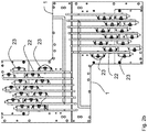
- the device for detection of the tactile sensitivity of a user comprises a base frame 1 and a mechanical system 2 attached to the base frame 1 .
- the mechanical system 2 can be moved relatively to the base frame 1 , and it comprises a resting area 3 for at least one fingertip of a user.
- the user rests the palm of his/her hand on a platform 101 in such a way that one of his/her fingertips, preferably the fingertip of his/her index finger, is in contact with the resting area 3 .
- the mechanical system 2 comprises a plurality of movable plate-shaped members 21 arranged side by side to each other in such a way that the resting area 3 is defined by the thicknesses of at least part of the upper edges of the plate-shaped members 21 .
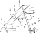
- the mechanical system 2 consists of a plurality of modular assemblies attached to each other, two embodiments of such assemblies being illustrated in FIGS. 3 a and 3 b.
- Each modular assembly consists of a plate-shaped member 21 , a lever 22 and an actuator 23 .
- each plate-shaped member 21 can be moved independently, the plate-shaped members 21 can be positioned at different heights so as to generate specific stimuli on the surface of the fingertip of the user.
- the envelope along the line joining the upper edges 211 of the plate-shaped members 21 defines a precise form which is changed according to the stimulus to be obtained.
- control unit which is adapted to generate control signals for the operation of the actuators 23 in order to create tactile stimuli on the fingertip of the user.
- the plate-shaped member 21 is connected to the corresponding actuator 23 through the lever 22 at an end 212 of the plate-shaped member 21 .
- the end 212 has an appropriate eyelet which receives the end pin of the lever 22 .
- the plate-shaped member 21 is hinged at an end 213 in such a way that the transition from the minimum height position to the maximum height position occurs when the plate-shaped member 21 is rotated about the end 213 .
- the end 213 has an eyelet for receiving a pin 11 supported by a pillar 12 , both integral with the base frame 1 , in such a way as to ensure the rotation thereof about the pin 11 received within the eyelet when the plate-shaped members are moved.
- the levers 22 can be attached to the actuators 23 through an attachment means of the actuator 23 which engages a slot 221 to adjust the arm of the lever 22 in length.
- each plate-shaped member 21 has an edge 214 projecting from the upper edge 211 at the resting area 3 towards the fingertip of the user.
- the upper portion of the plate-shaped member 21 extending towards the fingertip provides an appendix 215 having a projecting edge 214 in such a way that the resting area 3 is defined by the set of projecting edges 214 of each plate-shaped member 21 .
- the plate-shaped member 21 is moved in the same direction as the actuator 23 , meaning that, when the actuator is operated to be moved upward, the end 212 is also moved upward.
- FIG. 3 b illustrates a preferred and particularly advantageous embodiment: the lever 22 has at least one hole for receiving a pivot member 15 supported by two support members 14 .
- the support members 14 and the pivot member 15 are integral with the base frame 1 in such a way that, when the actuator 23 is operated to be moved upward, the end 212 of the plate-shaped member 21 is moved downward in the opposite direction.
- the plate-shaped members include plate-shaped members made of steel and plate-shaped members made of brass which are arranged alternately with each other in order to reduce friction when they are moved.
- FIGS. 2 a and 2 b illustrate the unique arrangement for actuators 23 , levers 22 and plate-shaped members 21 .
- the actuators 23 are divided in two groups arranged at opposite sides with respect to the plurality of plate-shaped members 21 .
- the actuators 23 in each group are arranged on two planes at different heights in such a way that the levers 22 of the actuators 23 lying on the upper plane are connected from above to each plate-shaped member 21 while the levers 22 of the actuators 23 lying on the lower plane are connected from below to each plate-shaped member 21 .
- the plate-shaped members 21 are arranged alternately with each other, i.e. the plate-shaped members in odd positions are driven by the group of actuators 23 on either the right side or the left side with reference to FIG. 2 a while the plate-shaped members in even positions are driven by the other group of actuators 23 .
- FIG. 2 b illustrates a top view of the mechanical system 2 with the plate-shaped members 21 being omitted.
- the levers 22 are arranged on an upper plane and a lower plane and, consequently, in case 28 levers are used, there are provided 14 pairs of levers with a common vertical plane.
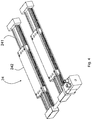
- the mechanical system 2 comprises a slider 24 adapted to slide the mechanical system 2 with respect to the base frame 1 .
- the mechanical system 2 has two types of movement: a vertical movement of each plate-shaped member 21 , particularly along axis B, and a longitudinal movement of the entire mechanical system 2 relatively to the base frame 1 as indicated by axis A.
- the slider system is driven by a corresponding drive unit which is not illustrated in the figures.
- the slider system can consist of a guide 241 integral with the base frame 1 and a slide 242 integral with the mechanical system.
- the stroke of the slides along the guides is about 500 millimeters in length.
- only one slide 242 is driven by a drive unit, while the other slide can be connected to the active slide through a rigid arm.
- the device of the present invention provides a system for detecting the pressure applied by the fingertip of the user.
- the detection system comprises a pressure sensor, particularly a piezoresistive sensor 4 , which is positioned on the projecting edge 214 of each plate-shaped member 21 , and an acquisition unit—not illustrated in the figure—which is connected to each piezoresistive sensor 4 .
- the piezoresistive sensors 4 are arranged in such a way to almost completely cover the resting area 3 in order to appropriately read the pressure distribution on the surface of the fingertip in contact with the resting area 3 .
- the senor 4 comprises a layer of a rigid material which is attached to the projecting edge 214 of each plate-shaped member 21 , the rigid layer having a plurality of electrodes deposited thereon, and a layer of a nanocomposite material with piezoresistive features.
- the nanocomposite material comprises an insulating polymeric matrix containing a plurality of electrically conductive elements as a dispersion.
- the rigid layer may consist of a layer of monocrystalline silicon or a layer of Kapton.
- Kapton makes easy to connect the sensor 4 with any acquisition unit.
- the layer of nanocomposite material may consist of an epoxy resin or acrylic resin which contains a dispersion of conductive elements with sharp corners, such as nano-tubes of carbon or nano-particles of gold, copper, silver, nickel, preferably wherein each particle is provided with nano-tips, such particles being known as a “spiky nano-particles”.
- this configuration is such that a pressure applied by the fingertip to the sensors 4 changes the distribution of the insulating spaces interposed among the conductive elements, thereby changing the specific electrical resistance and capacitance of the sensor 4 by either the tunnelling effect or a direct contact among the conductive elements, a phenomenon known as percolation.
- Such resistivity changes can be recorded by the acquisition unit in order to convert them into pressure values.
- the acquisition unit may comprise a resonant circuit which can be connected to the sensor 4 by means of metal foils.
- the frequency of a resonant circuit changes in a manner which can be directly correlated to the pressure change as described in document “A Robust Capacitive Digital Read-Out Circuit for a Scalable Tactile Skin”, A. Damilano, P. Housing Ros, A. Sanginario, A. Chiolerio, S. Bocchini, I. Roppolo, C. F. Pirri, S. Carrara, D. Demarchi, M. Crepaldi, IEEE Sensors Journal 2017 (in press) DOI: 10.1109/JSEN.2017.2681065, the contents of which should be considered as an integral part of the present specification.
- the upper surface of the layer of monocrystalline silicon may not be completely covered by the nano-composite material: therefore, the metal foils can be arranged on the “bare” portion of silicon and then welded or connected to wires by means of conductive resins for the connection with the acquisition unit.
- the independent movement of the plate-shaped members 21 is controlled by a control unit which is connected to the electronics—not illustrated in the figures—of the actuators 23 .
- the control unit generates control signals adapted to set the height of each individual plate-shaped member 21 in order to generate stimuli on the surface of the fingertip of the user in contact with the resting area 3 .
- control unit consists of a remote unit which controls a microcontroller connected to the actuators 23 and which comprises means for detecting the height of each plate-shaped member 21 .
- the microcontroller comprises one or more control units which can check the status of a group of actuators.
- the microcontroller is responsible for the activities performed in real-time mode, while the remote unit is responsible for the activities performed in non-real-time mode.
- the microcontroller may be a 12V-powered BeagleBone Black-type board.
- the board may incorporate a DAQ NI-type data acquisition system and a hardware device for the connection and control of the actuators 23 .
- the board may comprise a logic program designed to handle the state of each actuator 23 , particularly the number of steps, the direction of operation and the operation thereof.
- control unit of the microprocessor is interfaced with the data acquisition system.
- the microcontroller handling logic program is designed to move the actuators 23 in a consecutive manner and to assign the direction of movement and the number of steps to be performed to each actuator.
- control units of the microprocessor comprise 8-bit flip-flop-type electronic circuits.
- each flip-flop can handle four different actuators 23 , if there are 28 actuators, then 7 flip-flops are required.
- the microcontroller handling logic program is designed to set the status of the actuators 23 handled by the first flip-flop and then alternately operate each flip-flop by turning on the first flip-flop, then turning off the first flip-flop and turning on the second flip-flop, etc., in order to transfer all information related to the states of each actuator 23 .
- control signal can be generated, preferably by the remote unit through a control signal generating algorithm, in order to set the heights of each actuator 23 .
- the plate-shaped members 21 are mechanically synchronized by using a single control signal.
- the remote unit may be connected to both the microcontroller and the drive unit for the slider 24 so as to handle simultaneously both the stimuli to be presented to the fingertip and the proprioceptive system of the user.
- control signal sets the various heights of the plate-shaped members 21 so as to generate a sine wave-shaped profile along the longitudinal axis of the device of the present invention.
- the sine wave can be changed in temporal frequency, spatial frequency and amplitude according to the stimulus to be generated.
- FIG. 6 illustrates a concept diagram showing a possible use of the device.
- the user contacts the resting area 3 with the fingertip of his/her right index finger.
- the user is acoustically and visually isolated by means of a set of headphones and a blackout eye mask.
- Each trial 60 consists of two different stimuli to which the user is subjected.
- the remote unit 61 sends a control signal to the microcontroller 62 in order to generate the first stimulus.
- the microcontroller 62 sets the mechanical system 2 according to the above-described methodology, thereby operating the actuators and levers and setting the heights of the plate-shaped members so as to match the profile of the selected form and send the stimulus to the fingertip in contact with the plate-shaped members (in the presence or absence of the pressure sensor 4 ).
- the remote unit 61 sends a further control signal in order to generate the second stimulus.
- the user 63 indicates which stimulus was perceived with the greatest spatial frequency to the operator 64 , and the operator 64 creates a document with all the responses of the various users for any necessary evaluations.
- each trial 60 can include an interaction with the slider 24 in order to activate the proprioceptive system of the user 63 .
Landscapes
- Health & Medical Sciences (AREA)
- Life Sciences & Earth Sciences (AREA)
- Heart & Thoracic Surgery (AREA)
- Medical Informatics (AREA)
- Physics & Mathematics (AREA)
- Veterinary Medicine (AREA)
- Biophysics (AREA)
- Pathology (AREA)
- Engineering & Computer Science (AREA)
- Biomedical Technology (AREA)
- Public Health (AREA)
- General Health & Medical Sciences (AREA)
- Molecular Biology (AREA)
- Surgery (AREA)
- Animal Behavior & Ethology (AREA)
- Neurology (AREA)
- Physiology (AREA)
- Neurosurgery (AREA)
- User Interface Of Digital Computer (AREA)
- Measurement Of The Respiration, Hearing Ability, Form, And Blood Characteristics Of Living Organisms (AREA)
Abstract
Description
- The present invention relates to a device for detection of the tactile sensitivity of a user.
- The device comprises a base frame having a mechanical system attached thereto which can be moved relatively to the base frame and which has a resting area for the fingertip of at least one finger of the user.
- It is known that the sense of touch plays a key role in the behaviour of human beings: most interactions with the physical world occur through tactile sensations.
- Indeed, human beings use their hands, particularly the fingertips, to explore the external environment for a variety of tasks ranging from simple recognition and grasping of objects up to complex palpation procedures.
- When the surface of a fingertip contacts objects of various kinds, it is deformed.
- As a result, the surface of the fingertip is subjected to a complex distribution of deforming forces which stimulate the mechanoreceptors of a user. The information obtained from such a stimulation is fundamental to assist various tasks such as recognizing objects, detecting the roughness of a surface, etc.
- It is evident that investigating tactile sensitivity demands an ever-increasing attention not only for analysing the human behaviour but also in the field of robotics, where efficient tactile sensors are required to produce robotic fingers which can emulate human fingers.
- In addition, the ability of detecting tactile sensitivity plays a key role in the evaluation of neurological diseases of the autonomic and peripheral nervous system.
- This evaluation is performed by a method known in the art: the fingertip of the patient is moved along a resting area provided with reliefs to evaluate the spatial acuity of the fingertip skin.
- Generally, such an approach includes using resting areas which can generate different tactile stimuli and interviewing the user in order to evaluate his/her tactile sensitivity.
- A possible example of such a method as well as of a device for evaluating the tactile sensitivity is disclosed in document “Dynamic Investigation Test-rig on hAptics (DITA)”, F. Cannella, L. Scalise, E. Olivieri, M. Memeo, D. G. Caldwell, Journal of Physics: Conference Series 459, 2013.
- This document discloses a device for evaluating the tactile sensitivity, which comprises a resting area consisting of 17 different stimuli, each stimulus being associated to two reliefs separated by a flat surface.
- One of the two reliefs has an identical wavelength for each grating, while the other relief has a specific wavelength for each grating.
- The patient is instructed to slide his/her fingertip over the gratings in order to identify the different spatial frequencies thereof.
- However, this device cannot customize the stimuli which are presented to the patient.
- This limits the potential for analysing and studying patients because of the risk of detecting the tactile sensitivity of different patients in an approximate manner.
- In order to overcome this drawback, document “A dense array stimulator to generate arbitrary spatio-temporal tactile stimuli”, J. H. Killebrewa, S. J. Bensmaia, J. F. Dammann, P. Denchev, S. S. Hsiao, J. C. Craig, K. O. Johnson, J. Neurosc. Methods, 161(1):62-74, March 2007, discloses a system consisting of 400 pins arranged on a surface of about 1 cm2 and independently moved by respective 400 motors controlled by a specific software tool which can generate a wide range of stimuli on the fingertip of a patient when the surface of the fingertip contacts said pins.
- However, this approach is highly complex in design, especially from the mechanical point of view, with regards not only to the structural organization of the pins but also to the ability of moving them.
- Accordingly, this approach has the clear disadvantages of complex and composite systems, such as high cost, high risk of breakage or malfunction, excessive size, and handling problems.
- Therefore, there is a need—not satisfied by devices known in the art—for a device for detection of the tactile sensitivity of a user which overcomes the disadvantages as set forth above.
- Particularly, the invention aims to provide a device having a high accuracy in detection of neuronal diseases and neurodegenerative diseases, thereby allowing analyses to be carried out in a fast, efficient and repeatable manner.
- In addition, an object of the invention is to provide a device which is simple in design and which can be used not only for scientific investigations but also as a non-invasive tool for diagnosing and controlling diseases of the peripheral nervous system for clinical purposes.
- The present invention achieves the above objects by providing a device for detection of the tactile sensitivity of a user as described above, in which the mechanical system comprises a plurality of movable plate-shaped members which are arranged side by side to each other in such a way that the resting area is defined by the thicknesses of at least part of the upper edges of the plate-shaped members.
- Furthermore, each plate-shaped member is connected to an actuator which can be operated to independently move each plate-shaped member from a minimum height position to a maximum height position.
- Finally, a control unit is provided which is adapted to operate the actuators.
- Since the plate-shaped members can be independently moved under the control of the control unit, a wide range of stimuli can be generated for transmission to the user.
- In particular, the plate-shaped design of the mechanical system can achieve the best compromise between design simplicity and ability to generate a high range of tactile stimuli.
- As will become more apparent from the description of certain exemplary embodiments, each stimulus may have a sine-shaped profile whose spatial/temporal frequencies, amplitude and duration can be changed.
- This results in an improved resolution when the tactile sensitivity of different users is evaluated.
- Advantageously, such a configuration provides an increased variety of stimuli available with the use of a single set of movable members, thereby assuring an increased accuracy of the procedures and thus saving time.
- The features described immediately below are intended to further facilitate not only the design process but also the use of the device of the present invention.
- According to a first embodiment, each plate-shaped member is connected to a corresponding actuator through a lever which is attached to one end of the plate-shaped member.
- In addition, each plate-shaped member is hinged at the other end in such a way that the transition from the minimum height position to the maximum height position occurs when the plate-shaped member is rotated, particularly about the hinged end thereof.
- Since the plate-shaped members can be vertically moved by a corresponding lever, this results in a device which can measure the tactile sensitivity while being compact in size and portable.
- Furthermore, in order to differentiate and define the resting area, a variant embodiment provides that each plate-shaped member has an edge projecting from the upper edge thereof at the resting area towards the fingertip of the user.
- Thus, the resting area is elevated with respect to the upper edges of the plate-shaped members, and it is defined by the set of projecting edges of each plate-shaped member.
- It will be appreciated that, when stimuli are generated, the plate-shaped members are rotated through very small angles and, therefore, the rotation thereof is perceived by the user as a translation of each plate-shaped member towards the fingertip.
- Such a consideration is particularly important because, in this way, the above-described design simplicity can be kept without negatively affecting the quality of the generated stimuli and the quality of the analyses to be carried out.
- According to a preferred embodiment, the mechanical system comprises a slider adapted to slide the mechanical system with respect to the base frame.
- A drive unit is also provided for driving the slider.
- The actuation of the slider results in a movement of the mechanical system which activates the proprioception system of the user.
- As long as the hand and particularly the fingertip of the user are maintained in contact with the mechanical system, a movement of the mechanical system rotates the joints of the shoulder and arm, thereby activating the proprioception system of the user.
- As will become more evident from the exemplary embodiments illustrated and described hereinbelow, the fingertip is always in contact with the same plate-shaped members, even when the slider is driven.
- When the slider is driven, the forearm of the user is moved, the proprioception system is activated and a different input is provided which suggests to the user that he/she is exploring not just a point but a surface, thereby allowing for evaluations which are not only punctual but also superficial in nature.
- Therefore, the device of the present invention can evaluate both the tactile sensitivity and the proprioceptive system of a user.
- As a result, the device of the present invention can also be used with patients suffering from neurodegenerative diseases such as, for example, Parkinson's disease.
- According to a preferred embodiment, the plate-shaped members are made of different metal materials, particularly, two metal materials are used in such a way that each plate-shaped member made of one metal material is adjacent to and in contact with plate-shaped members made of the other metal material.
- Advantageously, brass and steel are used.
- The use of two different metal materials can limit the friction between the plate-shaped members, thereby reducing the wear thereof as well as the risk of failure for the mechanical system.
- Advantageously, said actuators are divided in two groups which are arranged on opposite sides with respect to the plurality of plate-shaped members.
- As will be illustrated hereinbelow, this variant embodiment allows the overall dimensions of the device of the present invention to be reduced while keeping design parameters constant in order to facilitate the handling of the plate-shaped members by the control unit.
- As previously anticipated, such a distribution of the actuators contributes to further reduce the size of the device of the present invention for portability purposes.
- According to an embodiment, the device of the present invention comprises a system for detecting the pressure applied by the fingertip of the user.
- Preferably, the pressure detection system comprises a pressure sensor positioned on the upper edge of each plate-shaped member at the resting area, and an acquisition unit connected to each pressure sensor.
- Preferably, the pressure detection system comprises one acquisition unit which is connected to all the pressure sensors.
- In this case, a parallel-channel device or multiplexer can be provided for connection.
- Such a configuration is particularly advantageous because it further improves the evaluation of tactile sensitivity of the user.
- In fact, the user can perceive the difference among different stimuli either by just touching the resting area, which indicates a high sensitivity, or by pressing the fingertip against the resting area, which indicates a low sensitivity.
- Advantageously, the pressure sensor can read the distribution of the pressure applied by the user.
- Furthermore, the pressure sensor can be used to check that the fingertip of the patient is appropriately placed on the resting area.
- It will be appreciated that any pressure sensor known in the art can be used.
- According to an improvement, a piezoresistive sensor can be provided.
- An example of such a sensor is disclosed in document “A tactile sensor device exploiting the tunable sensitivity of copper-PDMS piezoresistive composite”, S. Stassi, G. Canavese, F. Cosiansi, R. Gazia, M. Cocuzza, Procedia Engineering 47 (2012) 659-663, the contents of which should be considered as an integral part of the present specification.
- According to a further embodiment, the control unit is a remote unit which controls a microcontroller connected to the actuators.
- In particular, the remote unit generates command signals adapted to set the height of each plate-shaped member, and the microcontroller comprises means for detecting the height of each plate-shaped member.
- The control unit can create different control signals, preferably in the form of sine waves, by changing the duration and amplitude of a stimulus as well as the spatial and temporal frequencies thereof.
- Randomly combining such stimuli allows the tactile sensitivity of the user to be measured.
- Therefore, this makes it possible to optimally investigate the tactile sensitivity of each user by stimulating the surface of the fingertip in order to activate the mechanoreceptors.
- Thus, the control unit generates sinusoids which are transformed into mechanical movements: the profile of each sinusoid indicates a different height for each plate-shaped member.
- From the preceding description it becomes clear that the structural characteristics of the device of the present invention allow the tactile sensitivity of a user to be evaluated by simultaneously measuring different parameters in a precise and systematic manner, which results in a high level of accuracy.
- In addition, according to the peculiar embodiments described herein, a device for the detection of the tactile sensitivity of a user is provided which is compact in size and which makes use of plate-shaped members which can be moved both vertically and horizontally to detect the tactile sensitivity of the user and measure the pressure applied by the fingertip of the user in a reliable manner.
- These and other features and advantages of the present invention will become more fully apparent from the following description of certain non-limiting exemplary embodiments illustrated in the accompanying drawings, wherein:
-
FIGS. 1a and 1b illustrate two views of the device of the present invention according to a possible embodiment; -
FIGS. 2a and 2b illustrate the mechanical system of the device of the present invention; -
FIGS. 3a, 3b and 4 illustrate certain details of the mechanical system of the device of the present invention; -
FIG. 5 illustrates a concept diagram of the pressure sensor of the device of the present invention; -
FIG. 6 illustrates a functional diagram of the operation of the device of the present invention. - It will be appreciated that the figures accompanying the present patent application are included in order to better understand the advantages and features of the device of the present invention.
- Thus, these embodiments are intended to be merely illustrative and are not intended to limit the scope of the inventive concept of the present invention, which is to provide a device for detection of the tactile sensitivity of a user which allows measurements and evaluations to be carried out with a high degree of accuracy while keeping the components of the device simple in design.
-
FIGS. 1a and 1b illustrate a first embodiment of the device of the present invention, respectively in a version with anexternal covering case 10 and without the external case. - According to the embodiment illustrated in the Figures, the device for detection of the tactile sensitivity of a user comprises a
base frame 1 and amechanical system 2 attached to thebase frame 1. - As can be seen particularly in
FIG. 1b , themechanical system 2 can be moved relatively to thebase frame 1, and it comprises a restingarea 3 for at least one fingertip of a user. - In use, the user rests the palm of his/her hand on a
platform 101 in such a way that one of his/her fingertips, preferably the fingertip of his/her index finger, is in contact with the restingarea 3. - The
mechanical system 2 comprises a plurality of movable plate-shapedmembers 21 arranged side by side to each other in such a way that the restingarea 3 is defined by the thicknesses of at least part of the upper edges of the plate-shapedmembers 21. - As is clear from
FIGS. 2a and 2b , themechanical system 2 consists of a plurality of modular assemblies attached to each other, two embodiments of such assemblies being illustrated inFIGS. 3a and 3 b. - Each modular assembly consists of a plate-shaped
member 21, alever 22 and anactuator 23. - It is clear that, when each actuator 23 is operated, the respective plate-shaped
member 21 is independently moved through thelever 22 from a minimum height position to a maximum height position. - As will be seen hereinbelow, since each plate-shaped
member 21 can be moved independently, the plate-shapedmembers 21 can be positioned at different heights so as to generate specific stimuli on the surface of the fingertip of the user. - Indeed, the envelope along the line joining the
upper edges 211 of the plate-shapedmembers 21 defines a precise form which is changed according to the stimulus to be obtained. - There is provided a control unit—described in detail hereinbelow—which is adapted to generate control signals for the operation of the
actuators 23 in order to create tactile stimuli on the fingertip of the user. - With particular reference to
FIGS. 3a and 3b , the plate-shapedmember 21 is connected to the correspondingactuator 23 through thelever 22 at anend 212 of the plate-shapedmember 21. - According to the illustrated embodiment, the
end 212 has an appropriate eyelet which receives the end pin of thelever 22. - In addition, the plate-shaped
member 21 is hinged at anend 213 in such a way that the transition from the minimum height position to the maximum height position occurs when the plate-shapedmember 21 is rotated about theend 213. - According to the embodiment illustrated in
FIGS. 3a and 3b , theend 213 has an eyelet for receiving apin 11 supported by apillar 12, both integral with thebase frame 1, in such a way as to ensure the rotation thereof about thepin 11 received within the eyelet when the plate-shaped members are moved. - The
levers 22 can be attached to theactuators 23 through an attachment means of theactuator 23 which engages aslot 221 to adjust the arm of thelever 22 in length. - Further with particular reference to
FIGS. 3a and 3b , each plate-shapedmember 21 has anedge 214 projecting from theupper edge 211 at the restingarea 3 towards the fingertip of the user. - As illustrated, the upper portion of the plate-shaped
member 21 extending towards the fingertip provides anappendix 215 having a projectingedge 214 in such a way that the restingarea 3 is defined by the set of projectingedges 214 of each plate-shapedmember 21. - According to the embodiment illustrated in
FIG. 3a , the plate-shapedmember 21 is moved in the same direction as theactuator 23, meaning that, when the actuator is operated to be moved upward, theend 212 is also moved upward. - In contrast,
FIG. 3b illustrates a preferred and particularly advantageous embodiment: thelever 22 has at least one hole for receiving apivot member 15 supported by twosupport members 14. - The
support members 14 and thepivot member 15 are integral with thebase frame 1 in such a way that, when theactuator 23 is operated to be moved upward, theend 212 of the plate-shapedmember 21 is moved downward in the opposite direction. - With particular reference to the variant embodiment illustrated in
FIG. 2a , there are provided 28 plate-shapedmembers 21, each being 1 millimeter in thickness so that the restingarea 3 is 28 millimeters in length. - In addition, the plate-shaped members include plate-shaped members made of steel and plate-shaped members made of brass which are arranged alternately with each other in order to reduce friction when they are moved.
- Particularly,
FIGS. 2a and 2b illustrate the unique arrangement foractuators 23, levers 22 and plate-shapedmembers 21. - In order to minimize size and footprint and simultaneously provide each plate-shaped
member 21 with an identical lever linkage arrangement, theactuators 23 are divided in two groups arranged at opposite sides with respect to the plurality of plate-shapedmembers 21. - Furthermore, the
actuators 23 in each group are arranged on two planes at different heights in such a way that thelevers 22 of theactuators 23 lying on the upper plane are connected from above to each plate-shapedmember 21 while thelevers 22 of theactuators 23 lying on the lower plane are connected from below to each plate-shapedmember 21. - At the same time, the plate-shaped
members 21 are arranged alternately with each other, i.e. the plate-shaped members in odd positions are driven by the group ofactuators 23 on either the right side or the left side with reference toFIG. 2a while the plate-shaped members in even positions are driven by the other group ofactuators 23. - In this way, if the
proximal pin 11 inFIG. 2a engages the eyelets of the plate-shapedmembers 21 in even positions, then thedistal pin 11 inFIG. 2a engages the eyelets of the plate-shapedmembers 21 in odd positions, or vice versa. - Such a configuration is further elucidated in
FIG. 2b , which illustrates a top view of themechanical system 2 with the plate-shapedmembers 21 being omitted. - From
FIG. 2b , it is possible to appreciate the particular arrangement of theactuators 23 in order to minimize the footprint thereof to the maximum extent feasible. - As already anticipated in
FIG. 2a , thelevers 22 are arranged on an upper plane and a lower plane and, consequently, in case 28 levers are used, there are provided 14 pairs of levers with a common vertical plane. - With particular reference to
FIGS. 1b and 4, themechanical system 2 comprises aslider 24 adapted to slide themechanical system 2 with respect to thebase frame 1. - Thus, the
mechanical system 2 has two types of movement: a vertical movement of each plate-shapedmember 21, particularly along axis B, and a longitudinal movement of the entiremechanical system 2 relatively to thebase frame 1 as indicated by axis A. - The slider system is driven by a corresponding drive unit which is not illustrated in the figures.
- For example, the slider system can consist of a
guide 241 integral with thebase frame 1 and aslide 242 integral with the mechanical system. - With particular reference to
FIG. 4 , there are provided twoguides 241 and two slides 242: the stroke of the slides along the guides is about 500 millimeters in length. - Preferably, only one
slide 242 is driven by a drive unit, while the other slide can be connected to the active slide through a rigid arm. - With reference to
FIGS. 1a to 4, it will be appreciated that the fingertip of the user in contact with the restingarea 3 remains in contact with the set of plate-shapedmembers 21 even when themechanical system 2 is moved along axis A. - According to a preferred embodiment as illustrated in
FIG. 5 , the device of the present invention provides a system for detecting the pressure applied by the fingertip of the user. - The detection system comprises a pressure sensor, particularly a
piezoresistive sensor 4, which is positioned on the projectingedge 214 of each plate-shapedmember 21, and an acquisition unit—not illustrated in the figure—which is connected to eachpiezoresistive sensor 4. - As illustrated in
FIG. 5 , thepiezoresistive sensors 4 are arranged in such a way to almost completely cover theresting area 3 in order to appropriately read the pressure distribution on the surface of the fingertip in contact with the restingarea 3. - According to a possible embodiment, the
sensor 4 comprises a layer of a rigid material which is attached to the projectingedge 214 of each plate-shapedmember 21, the rigid layer having a plurality of electrodes deposited thereon, and a layer of a nanocomposite material with piezoresistive features. - Specifically, the nanocomposite material comprises an insulating polymeric matrix containing a plurality of electrically conductive elements as a dispersion.
- Preferably, the rigid layer may consist of a layer of monocrystalline silicon or a layer of Kapton.
- The use of Kapton makes easy to connect the
sensor 4 with any acquisition unit. - For example, the layer of nanocomposite material may consist of an epoxy resin or acrylic resin which contains a dispersion of conductive elements with sharp corners, such as nano-tubes of carbon or nano-particles of gold, copper, silver, nickel, preferably wherein each particle is provided with nano-tips, such particles being known as a “spiky nano-particles”.
- As is known, this configuration is such that a pressure applied by the fingertip to the
sensors 4 changes the distribution of the insulating spaces interposed among the conductive elements, thereby changing the specific electrical resistance and capacitance of thesensor 4 by either the tunnelling effect or a direct contact among the conductive elements, a phenomenon known as percolation. - Such resistivity changes can be recorded by the acquisition unit in order to convert them into pressure values.
- In order to maximize the accuracy of the parameters detected by the sensor, the acquisition unit may comprise a resonant circuit which can be connected to the
sensor 4 by means of metal foils. In fact, as a pressure applied to the nano-composite changes not only the resistive component but also the reactive component (the sum of which components represents the complex impedance), whether it is capacitive or inductive in nature, the frequency of a resonant circuit changes in a manner which can be directly correlated to the pressure change as described in document “A Robust Capacitive Digital Read-Out Circuit for a Scalable Tactile Skin”, A. Damilano, P. Motto Ros, A. Sanginario, A. Chiolerio, S. Bocchini, I. Roppolo, C. F. Pirri, S. Carrara, D. Demarchi, M. Crepaldi, IEEE Sensors Journal 2017 (in press) DOI: 10.1109/JSEN.2017.2681065, the contents of which should be considered as an integral part of the present specification. - According to this embodiment, for each
sensor 4, the upper surface of the layer of monocrystalline silicon may not be completely covered by the nano-composite material: therefore, the metal foils can be arranged on the “bare” portion of silicon and then welded or connected to wires by means of conductive resins for the connection with the acquisition unit. - As anticipated, the independent movement of the plate-shaped
members 21 is controlled by a control unit which is connected to the electronics—not illustrated in the figures—of theactuators 23. - The control unit generates control signals adapted to set the height of each individual plate-shaped
member 21 in order to generate stimuli on the surface of the fingertip of the user in contact with the restingarea 3. - Advantageously, the control unit consists of a remote unit which controls a microcontroller connected to the
actuators 23 and which comprises means for detecting the height of each plate-shapedmember 21. - Preferably, the microcontroller comprises one or more control units which can check the status of a group of actuators.
- According to this configuration, the microcontroller is responsible for the activities performed in real-time mode, while the remote unit is responsible for the activities performed in non-real-time mode.
- By way of an example, in an embodiment, the microcontroller may be a 12V-powered BeagleBone Black-type board.
- The board may incorporate a DAQ NI-type data acquisition system and a hardware device for the connection and control of the
actuators 23. - The board may comprise a logic program designed to handle the state of each actuator 23, particularly the number of steps, the direction of operation and the operation thereof.
- According to an exemplary embodiment, the control unit of the microprocessor is interfaced with the data acquisition system. The microcontroller handling logic program is designed to move the
actuators 23 in a consecutive manner and to assign the direction of movement and the number of steps to be performed to each actuator. - According to a further embodiment, the control units of the microprocessor comprise 8-bit flip-flop-type electronic circuits.
- Since each flip-flop can handle four
different actuators 23, if there are 28 actuators, then 7 flip-flops are required. - The microcontroller handling logic program is designed to set the status of the
actuators 23 handled by the first flip-flop and then alternately operate each flip-flop by turning on the first flip-flop, then turning off the first flip-flop and turning on the second flip-flop, etc., in order to transfer all information related to the states of eachactuator 23. - At this point, the control signal can be generated, preferably by the remote unit through a control signal generating algorithm, in order to set the heights of each
actuator 23. - It is evident that the configuration described just above allows the
actuators 23 to be synchronously and readily moved by sending a single control signal, without having to control each plate-shapedmember 21 separately. - In fact, the plate-shaped
members 21 are mechanically synchronized by using a single control signal. - According to a possible embodiment, the remote unit may be connected to both the microcontroller and the drive unit for the
slider 24 so as to handle simultaneously both the stimuli to be presented to the fingertip and the proprioceptive system of the user. - Preferably, the control signal sets the various heights of the plate-shaped
members 21 so as to generate a sine wave-shaped profile along the longitudinal axis of the device of the present invention. - As anticipated, the sine wave can be changed in temporal frequency, spatial frequency and amplitude according to the stimulus to be generated.
- Having described the characteristics of the device of the present invention,
FIG. 6 illustrates a concept diagram showing a possible use of the device. - The user contacts the resting
area 3 with the fingertip of his/her right index finger. - Then, the user is acoustically and visually isolated by means of a set of headphones and a blackout eye mask.
- Each
trial 60 consists of two different stimuli to which the user is subjected. - The
remote unit 61 sends a control signal to themicrocontroller 62 in order to generate the first stimulus. - The
microcontroller 62 sets themechanical system 2 according to the above-described methodology, thereby operating the actuators and levers and setting the heights of the plate-shaped members so as to match the profile of the selected form and send the stimulus to the fingertip in contact with the plate-shaped members (in the presence or absence of the pressure sensor 4). - Then, the
remote unit 61 sends a further control signal in order to generate the second stimulus. - Once the
trial 60 is completed, theuser 63 indicates which stimulus was perceived with the greatest spatial frequency to theoperator 64, and theoperator 64 creates a document with all the responses of the various users for any necessary evaluations. - Finally, each
trial 60 can include an interaction with theslider 24 in order to activate the proprioceptive system of theuser 63.
Claims (10)
Applications Claiming Priority (3)
| Application Number | Priority Date | Filing Date | Title |
|---|---|---|---|
| IT102017000041851 | 2017-04-14 | ||
| IT102017000041851A IT201700041851A1 (en) | 2017-04-14 | 2017-04-14 | Device for detecting a user's tactile sensitivity |
| PCT/IB2018/052575 WO2018189715A1 (en) | 2017-04-14 | 2018-04-12 | Device for detecting the tactile sensitivity of a user |
Publications (2)
| Publication Number | Publication Date |
|---|---|
| US20200046292A1 true US20200046292A1 (en) | 2020-02-13 |
| US11504005B2 US11504005B2 (en) | 2022-11-22 |
Family
ID=59746298
Family Applications (1)
| Application Number | Title | Priority Date | Filing Date |
|---|---|---|---|
| US16/603,234 Active 2040-01-07 US11504005B2 (en) | 2017-04-14 | 2018-04-12 | Device for detecting the tactile sensitivity of a user |
Country Status (4)
| Country | Link |
|---|---|
| US (1) | US11504005B2 (en) |
| EP (1) | EP3609386B1 (en) |
| IT (1) | IT201700041851A1 (en) |
| WO (1) | WO2018189715A1 (en) |
Families Citing this family (1)
| Publication number | Priority date | Publication date | Assignee | Title |
|---|---|---|---|---|
| CN111887809B (en) * | 2020-07-23 | 2022-08-16 | 李宝娟 | Portable neurological diagnosis tactile perception examination device |
-
2017
- 2017-04-14 IT IT102017000041851A patent/IT201700041851A1/en unknown
-
2018
- 2018-04-12 US US16/603,234 patent/US11504005B2/en active Active
- 2018-04-12 EP EP18721476.2A patent/EP3609386B1/en active Active
- 2018-04-12 WO PCT/IB2018/052575 patent/WO2018189715A1/en not_active Ceased
Non-Patent Citations (1)
| Title |
|---|
| Fischer, et al. "Tactile feedback for endoscopic surgery." Interactive technology and the new paradigm for healthcare: 114-117. (Year: 1995) * |
Also Published As
| Publication number | Publication date |
|---|---|
| EP3609386C0 (en) | 2024-06-05 |
| IT201700041851A1 (en) | 2018-10-14 |
| US11504005B2 (en) | 2022-11-22 |
| EP3609386B1 (en) | 2024-06-05 |
| WO2018189715A1 (en) | 2018-10-18 |
| EP3609386A1 (en) | 2020-02-19 |
Similar Documents
| Publication | Publication Date | Title |
|---|---|---|
| Drewing et al. | First evaluation of a novel tactile display exerting shear force via lateral displacement | |
| EP2569685B1 (en) | Detecting touch input and generating perceptible touch stimulus | |
| KR102536546B1 (en) | Finger-mounted device with sensors and haptics | |
| Tan et al. | Human factors for the design of force-reflecting haptic interfaces | |
| Delhaye et al. | Surface strain measurements of fingertip skin under shearing | |
| EP1527468B1 (en) | Device for detecting a mechanical actuation of an input element by using digital technology, and method for processing and converting the digital input signal into commands for controlling a load | |
| Srinivasan et al. | Tactile detection of slip: surface microgeometry and peripheral neural codes | |
| Li et al. | Non-invasive stimulation-based tactile sensation for upper-extremity prosthesis: a review | |
| Yi et al. | Biomimetic tactile sensors and signal processing with spike trains: A review | |
| Yoon et al. | iSoft: a customizable soft sensor with real-time continuous contact and stretching sensing | |
| US8884901B2 (en) | Shaped capacitive touch sensor, devices, and methods of use | |
| DE112018001457T5 (en) | SENSOR CONTROL | |
| Kyung et al. | Perceptual and biomechanical frequency response of human skin: implication for design of tactile displays | |
| CA2482567C (en) | Tactile mouse interface system for providing texture, shear and kinesthetic force | |
| Abbass et al. | Full-hand electrotactile feedback using electronic skin and matrix electrodes for high-bandwidth human–machine interfacing | |
| CN118750726A (en) | A mirror tactile feedback rehabilitation system | |
| US11504005B2 (en) | Device for detecting the tactile sensitivity of a user | |
| Barra et al. | A versatile robotic platform for the design of natural, three-dimensional reaching and grasping tasks in monkeys | |
| Jayawant | Tactile sensing in robotics | |
| Gardner et al. | Neurophysiology of prehension. III. Representation of object features in posterior parietal cortex of the macaque monkey | |
| Delhaye et al. | Robo-psychophysics: extracting behaviorally relevant features from the output of sensors on a prosthetic finger | |
| McLaren et al. | What is affective touch made of? a soft capacitive sensor array reveals the interplay between shear, normal stress and individuality | |
| CN210199703U (en) | A flexible tactile glove based on supercapacitive sensing principle | |
| Wang et al. | A smart finger for robotic tactile sensing of surface/subsurface patterns based on a high-density piezoresistive sensor array | |
| KR102698017B1 (en) | A system for interacting with each other using artificial skin structure |
Legal Events
| Date | Code | Title | Description |
|---|---|---|---|
| FEPP | Fee payment procedure |
Free format text: ENTITY STATUS SET TO UNDISCOUNTED (ORIGINAL EVENT CODE: BIG.); ENTITY STATUS OF PATENT OWNER: SMALL ENTITY |
|
| FEPP | Fee payment procedure |
Free format text: ENTITY STATUS SET TO SMALL (ORIGINAL EVENT CODE: SMAL); ENTITY STATUS OF PATENT OWNER: SMALL ENTITY |
|
| AS | Assignment |
Owner name: UNIVERSITA DEGLI STUDI DI GENOVA, ITALY Free format text: ASSIGNMENT OF ASSIGNORS INTEREST;ASSIGNORS:CANNELLA, FERDINANDO;D'ANGELO, MARIA LAURA;CHIOLERIO, ALESSANDRO;REEL/FRAME:051137/0207 Effective date: 20191004 Owner name: FONDAZIONE ISTITUTO ITALIANO DI TECNOLOGIA, ITALY Free format text: ASSIGNMENT OF ASSIGNORS INTEREST;ASSIGNORS:CANNELLA, FERDINANDO;D'ANGELO, MARIA LAURA;CHIOLERIO, ALESSANDRO;REEL/FRAME:051137/0207 Effective date: 20191004 |
|
| STPP | Information on status: patent application and granting procedure in general |
Free format text: DOCKETED NEW CASE - READY FOR EXAMINATION |
|
| STPP | Information on status: patent application and granting procedure in general |
Free format text: NOTICE OF ALLOWANCE MAILED -- APPLICATION RECEIVED IN OFFICE OF PUBLICATIONS |
|
| STCF | Information on status: patent grant |
Free format text: PATENTED CASE |