US2019613A - Sodium vapor lamp - Google Patents
Sodium vapor lamp Download PDFInfo
- Publication number
- US2019613A US2019613A US682753A US68275333A US2019613A US 2019613 A US2019613 A US 2019613A US 682753 A US682753 A US 682753A US 68275333 A US68275333 A US 68275333A US 2019613 A US2019613 A US 2019613A
- Authority
- US
- United States
- Prior art keywords
- envelope
- anodes
- conductors
- alkali metal
- stem
- Prior art date
- Legal status (The legal status is an assumption and is not a legal conclusion. Google has not performed a legal analysis and makes no representation as to the accuracy of the status listed.)
- Expired - Lifetime
Links
Images
Classifications
-
- H—ELECTRICITY
- H01—ELECTRIC ELEMENTS
- H01J—ELECTRIC DISCHARGE TUBES OR DISCHARGE LAMPS
- H01J61/00—Gas-discharge or vapour-discharge lamps
- H01J61/70—Lamps with low-pressure unconstricted discharge having a cold pressure < 400 Torr
- H01J61/74—Lamps with low-pressure unconstricted discharge having a cold pressure < 400 Torr having a main light-emitting filling of difficult vaporisable metal vapour, e.g. sodium
Definitions
- This invention relates to electric discharge devices and more particularly to devices of this character that are to be employed for illuminat- I
- an alkali I metal vapor lamp comprising an elongated or tubular envelope having therein four anodes and a v cathode. Also located within said envelope is an 15 alkali metal vapor such as sodium.
- the anodes are so arranged that two of them are disposed near one end of the envelope and the other two are disposed near the other end of the envelope.
- One anode at one end is electrically connected to 20 an anode at the other end.
- the secondary of a low voltage transformer 25 has its ends respectively connected to each pair of anodes and the midpoint thereof connected to the thermionic cathode.
- the current flow between the anodes and cathode is 30 divided in two paths, one path being between one of the anodes of the pair and the cathode and the other path between the other anode of the pair and the cathode.
- Temperature distribution is of prime importance because it is well known that the equilibrium vapor pressure of the 40 alkali metal'within the envelope is dependent upon the temperature of the envelope at the coolest portion thereof. Another factor that sometimes must be taken into consideration is blackening of the envelope adjacent the anodes. This,
- substantially all of the current on each half cycle shall travel to a 55 single anode.
- that portion of the envelope adjacent the anodes may be kept at the proper temperature.
- the anodes may be located near the lower end of the envelope because that portion is generallycovered by a suitable base or the light passing therethrough is in most cases not utilized.
- an object of my invention is to provide an improved alkali metal vapor lamp having improved electrical characteristics.
- Another object of my invention is to dis- 10 pose the anodes in an alkali metal vapor lamp that substantially all the discharge current will travel between the cathode and a single anode on onehalf cycle of the alternating current source of potential connected thereto.
- a still further object of my invention is to provide an alternating current alkali metal vapo lamp having its anodes located in the neck portion of the envelope thereof.
- Figure 1 represents a cross-sectional view with some. of the parts in elevation of my improved luminous discharge device
- Figure 2 represents a cross-sectional view taken on line IIII in the direction of the arrows.
- my invention comprises an alkali metal vapor lamp including an alkaline metal resisting vitreous envelope 9 having anodes III and II and a cathode I2 therein.
- An alkali metal such as sodium, rubidium, caesium or the like together with a small proportion of neon, is also contained in said envelope.
- the major portion I3 of the envelope is substantially spherical in shape and has a cylindrical neck portion I 4 integral therewith. Fusedly sealed to the lower end'of said neck I4 is a reentrant tube I5 having a press I Ii at the upper end thereof.
- Hermetically sealed in said press are a plural- 40 ity of leading-in conductors I1, III, III and 20 extending exteriorly and interiorlypf said envelope, with the portions thereof extending interiorly thereof being rigid supporting members.
- the cathode I2 Secured to the upper ends of the conductors I1 and I8 is the cathode I2 consisting of a coiled tungsten filament around which is located a nickel coiled filament with calcium, barium or strontium oxide or carbonates generally employed for electron emission purposes.
- and 22 of molybdenum or the like are secured respectively at their short arms 2
- the long arms of said inverted L-shaped rods extend towardsthe lower end oi. the envelope and terminate below the 'press l6 and adjacent the lower portion of the interior of said envelope.
- and 22 respectively are the main anodes I0 and II.
- Each of said anodes consists of an annular band or ribbon of a refractory metal such as molybdenum or the like.
- the anodes 2i and 22 are concentric with the stem l5 and are in substantially the same horizontal plane and spaced from each other.
- a nickel shield 23 to protect the press, seals and stem from bombardment.
- a base 24 is secured. to the lower portion of said envelope and the exterior portions of the leadingin conductors are appropriately secured to the usual contact pins carried by said base.
- the anodes Ill and Ii are located a suiilcient depth in the neck of the envelope and the base 24 is of such a depth that the base surrounds that portion of the envelope which may become blackened because of anode sputtering.
- the interior rigid portion oi. the leading-in conductors are provided with insulating sleeves 28 composed of alundum or the like. These sleeves surround the leading-in and supporting conductors and protect said conductors from bombardment and consequent sputtering.
- a double walled chamber 25 which may be either filled with a gas having a low heat conductivity characteristic, or may be highly evacuated.
- An electric device comprising an envelope having a reentrant stem terminating in a press, an alkali metal, a thermionic cathode and a plurality or main anodes in said envelope, all of said anodes surrounding said stem, a plurality of supporting conductors sealed in said press and electrically connected to said cathode and anodes.
- An alkali metal vapor lamp comprising an envelope having a press, an alkali metal, a thermionically active cathode, a starting anode and a plurality of main anodes therein, said main anodes encircling said stem, all of said main anodes being located at one end-oi said envelope.
- An alkali metal vapor lamp comprising an envelope, sodium, a plurality of main anodes, and a thermionically active cathode therein, said main 6 anodes located at one end of said envelope, a base mounted on said envelope, said base encircling said main anodes and extending above the upper edge of said anodes.
- An alkali metal vapor lamp comprising an 10 envelope, sodium, a plurality of main anodes and a thermionically active cathode therein, said envelope having a neck, said main anodes being located in said neck, a base mounted on the neck of said envelope and encircling said main anodes 15 I and extending above the upper edge oi said anodes.
- An alkali metal vapor lamp comprising an envelope, sodium, a plurality of main anodes, a starting anode and a thermionically active cath- 20 ode therein, said envelope having a reentrant stem, a plurality of leads carried by said stem, said electrodes being electrically connected to said leads, all of said main anodes surrounding said stem and a shielding means between said main 25 anodes and said stem.
- An alkali metal vapor lamp comprising an envelope having a press, an alkali metal therein, a plurality of conductors sealed in said press, a thermionically active cathode secured to two 01 said conductors, a plurality of electrically conductive supports secured to said other two conductors and extending therefrom, a main anode secured to each of said supports, all of said main anodes being located at that end of the envelope containing the press, and discharge starting means located near said cathode.
- An alkali metal vapor lamp comprising an envelope having a press, an alkali metal therein, tour conductors sealed in said press, a. thermioni- 40 cally active cathode connected to the two intermediate conductors, and a pair of main anodes electrically connected to the two end conductors, all oi. said main anodes in said envelope being located at that end of the envelope containing 45 said press, and insulating means on said conductors to prevent discharge therebetween, and means forming a part oi. said lamp for initiating a discharge in said device.
- An electric discharge device comprising an 50 envelope having a reentrant stem, an ionizable medium therein, a plurality of conductors carried by said stem, a thermionically active cathode secured to two of said conductors, inverted L- shaped conductors secured to two other of said conductors, main anodes surrounding said stem and secured to the long arms of said inverted L- shaped conductors, and insulating sleeves surrounding the major portion of all of said condtuctors, all or said main anodes surrounding said s em.
- An alkali metal vapor lamp comprising an envelope, sodium, a plurality ,of main anodes, a starting anode and a thermionically active cathode therein, said envelope having a reentrant stem, a plurality of leads carried by said stem, said electrodes being electrically connected to said leads, all of said main anodes surrounding said stem and a metallic shielding means located bebetween said main anodes and said stem, said] shielding means being entirely supported by said! stem. 5
Description
Nov. 5, 19350 J. w MARDEN SODIUM VAPOR LAMP Filed July 29, 1933 INVENTOR J. W. MflFDf/V )W %fi ATTORNEY Patented Nov. 5, 1935 UNITED STATES PATENT OFFICE SODIUM VAPOR LAMP Pennsylvania Application July 29; .1933, Serial No. 682,753
9 Claims. (Cl. 176-122) This invention relates to electric discharge devices and more particularly to devices of this character that are to be employed for illuminat- I In said application I have described an alkali I metal vapor lamp comprising an elongated or tubular envelope having therein four anodes and a v cathode. Also located within said envelope is an 15 alkali metal vapor such as sodium. The anodes are so arranged that two of them are disposed near one end of the envelope and the other two are disposed near the other end of the envelope. One anode at one end is electrically connected to 20 an anode at the other end. In like manner, the
other anode at said first mentioned end is connected to the other anode at the second mentioned end.
The secondary of a low voltage transformer 25 has its ends respectively connected to each pair of anodes and the midpoint thereof connected to the thermionic cathode. When one pair of anodes is positive with respect to the cathode, the current flow between the anodes and cathode is 30 divided in two paths, one path being between one of the anodes of the pair and the cathode and the other path between the other anode of the pair and the cathode.
In the course of my experimentations with 35 lamps of this character I have observed that temperature distribution is an important factor for efilcient lamp operation. Temperature distribution is of prime importance because it is well known that the equilibrium vapor pressure of the 40 alkali metal'within the envelope is dependent upon the temperature of the envelope at the coolest portion thereof. Another factor that sometimes must be taken into consideration is blackening of the envelope adjacent the anodes. This,
45 I believe, to be due to anode sputtering.
In order that any anode sputtering may be confined where it is least noticeable and so that'I may properly fix the temperature distribution of an alkali metal lamp, I have developed the fol- 50 lowing invention.
Instead of dividing the current between the two anodes on each half cycle of the alternating current input, I prefer that substantially all of the current on each half cycle shall travel to a 55 single anode. By this means, that portion of the envelope adjacent the anodes may be kept at the proper temperature. In addition, the anodes may be located near the lower end of the envelope because that portion is generallycovered by a suitable base or the light passing therethrough is in most cases not utilized.
Accordingly an object of my invention is to provide an improved alkali metal vapor lamp having improved electrical characteristics.
Another object of my invention is to dis- 10 pose the anodes in an alkali metal vapor lamp that substantially all the discharge current will travel between the cathode and a single anode on onehalf cycle of the alternating current source of potential connected thereto.
A still further object of my invention is to provide an alternating current alkali metal vapo lamp having its anodes located in the neck portion of the envelope thereof.
Other objects and advantages of my invention will become readily apparent from the following description and appended drawing wherein,
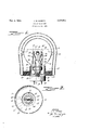
Figure 1 represents a cross-sectional view with some. of the parts in elevation of my improved luminous discharge device; and
Figure 2 represents a cross-sectional view taken on line IIII in the direction of the arrows.
As illustrated, my invention comprises an alkali metal vapor lamp including an alkaline metal resisting vitreous envelope 9 having anodes III and II and a cathode I2 therein. An alkali metal such as sodium, rubidium, caesium or the like together with a small proportion of neon, is also contained in said envelope. The major portion I3 of the envelope is substantially spherical in shape and has a cylindrical neck portion I 4 integral therewith. Fusedly sealed to the lower end'of said neck I4 is a reentrant tube I5 having a press I Ii at the upper end thereof.
Hermetically sealed in said press are a plural- 40 ity of leading-in conductors I1, III, III and 20 extending exteriorly and interiorlypf said envelope, with the portions thereof extending interiorly thereof being rigid supporting members. Secured to the upper ends of the conductors I1 and I8 is the cathode I2 consisting of a coiled tungsten filament around which is located a nickel coiled filament with calcium, barium or strontium oxide or carbonates generally employed for electron emission purposes. Inverted l.'-shaped rods 2| and 22 of molybdenum or the like are secured respectively at their short arms 2| and 22' to the conductors I9 and 20. These short arms extend towards each other and are spaced an appropriate distance from the ends s and act as auxiliary or starting anodes so that adischarge may be eil'ectively initiated within said envelope at the voltages employed.
The long arms of said inverted L-shaped rods extend towardsthe lower end oi. the envelope and terminate below the 'press l6 and adjacent the lower portion of the interior of said envelope. Secured by welding to the lower ends 0! said arms 2| and 22 respectively are the main anodes I0 and II. Each of said anodes consists of an annular band or ribbon of a refractory metal such as molybdenum or the like. The anodes 2i and 22 are concentric with the stem l5 and are in substantially the same horizontal plane and spaced from each other.
.Surrounding the press and a major portion of said stem I5 is a nickel shield 23 to protect the press, seals and stem from bombardment. A base 24 is secured. to the lower portion of said envelope and the exterior portions of the leadingin conductors are appropriately secured to the usual contact pins carried by said base.
It is well known that when one body is contiguous with another body there is formed a heat-conducting path and that ii the temperature of one body is elevated above that of the other, the temperature of the first mentioned body will be lowered and that oi. the other will be increased because oi heat transferred from the body of elevated temperature to that of lower temperature. By so disposing the anodes 2| and 22 in the neck of the envelope, the temperature of the envelope at the lower portion thereof may be of such a magnitude that the heat variations thereat, due to basing, are compensated for. This result is further dependent on having substantially all of the discharge current of the hall cycles of the alternating ,current pass directly between the respective anodes I 0 and I I and the cathode i2.
The anodes Ill and Ii are located a suiilcient depth in the neck of the envelope and the base 24 is of such a depth that the base surrounds that portion of the envelope which may become blackened because of anode sputtering. The interior rigid portion oi. the leading-in conductors are provided with insulating sleeves 28 composed of alundum or the like. These sleeves surround the leading-in and supporting conductors and protect said conductors from bombardment and consequent sputtering.-
To augment the eiliciency oi the lamp, the same is provided with a double walled chamber 25 which may be either filled with a gas having a low heat conductivity characteristic, or may be highly evacuated. The chamber 25, together with an insulating asbestos packing 2'l, surrounds said lamp and prevents air circulation around the exterior of the envelope thereof.
Although my invention is susceptible to numerous modifications, it is not to be limited to the exact construction herein specified but is to be limited only by the prior art.
What is claimed is:
1. An electric device comprising an envelope having a reentrant stem terminating in a press, an alkali metal, a thermionic cathode and a plurality or main anodes in said envelope, all of said anodes surrounding said stem, a plurality of supporting conductors sealed in said press and electrically connected to said cathode and anodes.
2. An alkali metal vapor lamp comprising an envelope having a press, an alkali metal, a thermionically active cathode, a starting anode and a plurality of main anodes therein, said main anodes encircling said stem, all of said main anodes being located at one end-oi said envelope.
3. An alkali metal vapor lamp comprising an envelope, sodium, a plurality of main anodes, and a thermionically active cathode therein, said main 6 anodes located at one end of said envelope, a base mounted on said envelope, said base encircling said main anodes and extending above the upper edge of said anodes.
4. An alkali metal vapor lamp comprising an 10 envelope, sodium, a plurality of main anodes and a thermionically active cathode therein, said envelope having a neck, said main anodes being located in said neck, a base mounted on the neck of said envelope and encircling said main anodes 15 I and extending above the upper edge oi said anodes. Y
5. An alkali metal vapor lamp comprising an envelope, sodium, a plurality of main anodes, a starting anode and a thermionically active cath- 20 ode therein, said envelope having a reentrant stem, a plurality of leads carried by said stem, said electrodes being electrically connected to said leads, all of said main anodes surrounding said stem and a shielding means between said main 25 anodes and said stem.
6. An alkali metal vapor lamp comprising an envelope having a press, an alkali metal therein, a plurality of conductors sealed in said press, a thermionically active cathode secured to two 01 said conductors, a plurality of electrically conductive supports secured to said other two conductors and extending therefrom, a main anode secured to each of said supports, all of said main anodes being located at that end of the envelope containing the press, and discharge starting means located near said cathode.
7. An alkali metal vapor lamp comprising an envelope having a press, an alkali metal therein, tour conductors sealed in said press, a. thermioni- 40 cally active cathode connected to the two intermediate conductors, and a pair of main anodes electrically connected to the two end conductors, all oi. said main anodes in said envelope being located at that end of the envelope containing 45 said press, and insulating means on said conductors to prevent discharge therebetween, and means forming a part oi. said lamp for initiating a discharge in said device.
8. An electric discharge device comprising an 50 envelope having a reentrant stem, an ionizable medium therein, a plurality of conductors carried by said stem, a thermionically active cathode secured to two of said conductors, inverted L- shaped conductors secured to two other of said conductors, main anodes surrounding said stem and secured to the long arms of said inverted L- shaped conductors, and insulating sleeves surrounding the major portion of all of said condtuctors, all or said main anodes surrounding said s em.
9. An alkali metal vapor lamp comprising an envelope, sodium, a plurality ,of main anodes, a starting anode and a thermionically active cathode therein, said envelope having a reentrant stem, a plurality of leads carried by said stem, said electrodes being electrically connected to said leads, all of said main anodes surrounding said stem and a metallic shielding means located bebetween said main anodes and said stem, said] shielding means being entirely supported by said! stem. 5
' JOHN W. MARDEN.
Priority Applications (1)
| Application Number | Priority Date | Filing Date | Title |
|---|---|---|---|
| US682753A US2019613A (en) | 1933-07-29 | 1933-07-29 | Sodium vapor lamp |
Applications Claiming Priority (1)
| Application Number | Priority Date | Filing Date | Title |
|---|---|---|---|
| US682753A US2019613A (en) | 1933-07-29 | 1933-07-29 | Sodium vapor lamp |
Publications (1)
| Publication Number | Publication Date |
|---|---|
| US2019613A true US2019613A (en) | 1935-11-05 |
Family
ID=24740990
Family Applications (1)
| Application Number | Title | Priority Date | Filing Date |
|---|---|---|---|
| US682753A Expired - Lifetime US2019613A (en) | 1933-07-29 | 1933-07-29 | Sodium vapor lamp |
Country Status (1)
| Country | Link |
|---|---|
| US (1) | US2019613A (en) |
-
1933
- 1933-07-29 US US682753A patent/US2019613A/en not_active Expired - Lifetime
Similar Documents
| Publication | Publication Date | Title |
|---|---|---|
| US3250934A (en) | Electric discharge device having heat conserving shields and sleeve | |
| US4963790A (en) | Low wattage metal halide discharge lamp | |
| US2549355A (en) | Fluorescent lamp | |
| US2201720A (en) | Thermionic cathode structure | |
| US2545884A (en) | High-pressure mercury vapor electric discharge lamp | |
| US2518879A (en) | Hydrogen thyratron | |
| US2241362A (en) | Electron emissive cathode | |
| US1874753A (en) | Controlled arc discharge apparatus | |
| US2438181A (en) | Fluorescent and/or cathode glow lamp and method | |
| US2273450A (en) | High pressure metal vapor lamp | |
| US2009839A (en) | Thermionic cathode | |
| US2019613A (en) | Sodium vapor lamp | |
| US2241345A (en) | Electron emissive cathode | |
| US2283639A (en) | Electric discharge device | |
| US1989786A (en) | Base and based electric device | |
| US2660692A (en) | High-pressure discharge lamp | |
| US1790153A (en) | Electrical discharge device and method of operation | |
| US3275885A (en) | High pressure discharge lamp with electrolysis preventing means | |
| US2076286A (en) | Electric gaseous discharge device | |
| US2236289A (en) | Thermionic device | |
| US2121591A (en) | Grid glow tube with zero temperature effect | |
| US2324766A (en) | Electron discharge device | |
| US2089654A (en) | Electrical discharge device | |
| US2330042A (en) | Long life high pressure lamp | |
| US1945746A (en) | Electron discharge device with indirectly heated cathode |