US20190219084A1 - Self-drilling anchor assembly - Google Patents
Self-drilling anchor assembly Download PDFInfo
- Publication number
- US20190219084A1 US20190219084A1 US16/243,541 US201916243541A US2019219084A1 US 20190219084 A1 US20190219084 A1 US 20190219084A1 US 201916243541 A US201916243541 A US 201916243541A US 2019219084 A1 US2019219084 A1 US 2019219084A1
- Authority
- US
- United States
- Prior art keywords
- drill bit
- anchor
- shank
- self
- anchor assembly
- Prior art date
- Legal status (The legal status is an assumption and is not a legal conclusion. Google has not performed a legal analysis and makes no representation as to the accuracy of the status listed.)
- Granted
Links
- 238000005553 drilling Methods 0.000 title claims abstract description 144
- 239000000758 substrate Substances 0.000 claims abstract description 95
- 230000015572 biosynthetic process Effects 0.000 claims abstract description 32
- 238000005520 cutting process Methods 0.000 claims description 150
- 239000000463 material Substances 0.000 claims description 85
- 239000007787 solid Substances 0.000 claims description 21
- 238000009434 installation Methods 0.000 abstract 1
- 238000000034 method Methods 0.000 description 31
- 238000005755 formation reaction Methods 0.000 description 28
- 229910000975 Carbon steel Inorganic materials 0.000 description 18
- 239000010962 carbon steel Substances 0.000 description 18
- 238000004891 communication Methods 0.000 description 18
- 230000007797 corrosion Effects 0.000 description 17
- 238000005260 corrosion Methods 0.000 description 17
- 229910000831 Steel Inorganic materials 0.000 description 10
- 239000010959 steel Substances 0.000 description 10
- 230000008901 benefit Effects 0.000 description 4
- 230000007246 mechanism Effects 0.000 description 3
- 230000000712 assembly Effects 0.000 description 2
- 238000000429 assembly Methods 0.000 description 2
- 238000002788 crimping Methods 0.000 description 2
- 238000004519 manufacturing process Methods 0.000 description 2
- 239000002184 metal Substances 0.000 description 2
- 238000005452 bending Methods 0.000 description 1
- 238000010276 construction Methods 0.000 description 1
- 239000012530 fluid Substances 0.000 description 1
- 238000009415 formwork Methods 0.000 description 1
- 238000012986 modification Methods 0.000 description 1
- 230000004048 modification Effects 0.000 description 1
- 238000009987 spinning Methods 0.000 description 1
- 238000003466 welding Methods 0.000 description 1
Images


Classifications
-
- F—MECHANICAL ENGINEERING; LIGHTING; HEATING; WEAPONS; BLASTING
- F16—ENGINEERING ELEMENTS AND UNITS; GENERAL MEASURES FOR PRODUCING AND MAINTAINING EFFECTIVE FUNCTIONING OF MACHINES OR INSTALLATIONS; THERMAL INSULATION IN GENERAL
- F16B—DEVICES FOR FASTENING OR SECURING CONSTRUCTIONAL ELEMENTS OR MACHINE PARTS TOGETHER, e.g. NAILS, BOLTS, CIRCLIPS, CLAMPS, CLIPS OR WEDGES; JOINTS OR JOINTING
- F16B13/00—Dowels or other devices fastened in walls or the like by inserting them in holes made therein for that purpose
- F16B13/002—Dowels or other devices fastened in walls or the like by inserting them in holes made therein for that purpose self-cutting
- F16B13/003—Dowels or other devices fastened in walls or the like by inserting them in holes made therein for that purpose self-cutting with a separate drilling bit attached to or surrounded by the dowel element
-
- F—MECHANICAL ENGINEERING; LIGHTING; HEATING; WEAPONS; BLASTING
- F16—ENGINEERING ELEMENTS AND UNITS; GENERAL MEASURES FOR PRODUCING AND MAINTAINING EFFECTIVE FUNCTIONING OF MACHINES OR INSTALLATIONS; THERMAL INSULATION IN GENERAL
- F16B—DEVICES FOR FASTENING OR SECURING CONSTRUCTIONAL ELEMENTS OR MACHINE PARTS TOGETHER, e.g. NAILS, BOLTS, CIRCLIPS, CLAMPS, CLIPS OR WEDGES; JOINTS OR JOINTING
- F16B13/00—Dowels or other devices fastened in walls or the like by inserting them in holes made therein for that purpose
- F16B13/04—Dowels or other devices fastened in walls or the like by inserting them in holes made therein for that purpose with parts gripping in the hole or behind the reverse side of the wall after inserting from the front
- F16B13/06—Dowels or other devices fastened in walls or the like by inserting them in holes made therein for that purpose with parts gripping in the hole or behind the reverse side of the wall after inserting from the front combined with expanding sleeve
- F16B13/063—Dowels or other devices fastened in walls or the like by inserting them in holes made therein for that purpose with parts gripping in the hole or behind the reverse side of the wall after inserting from the front combined with expanding sleeve by the use of an expander
- F16B13/065—Dowels or other devices fastened in walls or the like by inserting them in holes made therein for that purpose with parts gripping in the hole or behind the reverse side of the wall after inserting from the front combined with expanding sleeve by the use of an expander fastened by extracting the screw, nail or the like
Definitions
- Masonry structures are widely used throughout the construction industry.
- One type of masonry structure is a concrete structure (such as a concrete wall, a concrete floor, or a concrete ceiling).
- Such concrete structures are typically constructed from fluid concrete poured into a mold or other suitable formwork. After being pouring, the concrete cures and hardens to form the concrete structure.
- known anchor assemblies are often used to attach fixtures to the concrete structure. Certain issues exist with various known anchor assemblies used to attach fixtures to masonry structures such as concrete structures.
- an installer To attach a fixture to a concrete structure, an installer must first drill a hole in the concrete structure using a suitable drill with a suitable drill bit. The installer then needs to remove the drill bit from the drilled hole, put down the drill with the drill bit in a suitable location, and then pick up the anchor assembly and the appropriate anchor driving tool and drive the anchor into the drilled hole. This can be a relatively time consuming process.
- drill bits that are repeatedly used to drill holes in masonry structures such as concrete walls are typically made from an relatively strong material (such as carbon steel with a carbide blade tip brazed to it) so that they do not wear out or become dull too quickly. Such drill bits are relatively expensive.
- Various embodiments of the present disclosure provide a self-drilling anchor assembly and a method of installing the self-drilling anchor assembly in a substrate (such as masonry structure).
- the self-drilling anchor assembly of the present disclosure is quick and easy to install.
- the self-drilling anchor assembly and the methods of the present disclosure address and overcome the above described issues, and specifically reduce the time necessary to install an anchor assembly in a substrate (such as a masonry structure).
- the present disclosure provides a self-drilling anchor assembly including a drill bit and an anchor positioned over and attached to the drill bit.
- the drill bit includes: (a) a shank, (b) a drill head integrally connected to one end of the shank, and (c) a threaded tail integrally connected to an opposite end of the shank.
- the tail includes a mechanical engaging structure that is engageable by a tool to rotate the drill bit, and a helical thread formation to facilitate attachment of a securing device (such as a nut and a washer) to the tail of the drill bit.
- the anchor includes: (i) an elongated generally tubular body including an inner surface defining a longitudinally extending inner channel, and (ii) a head integrally connected to and extending from a rear end of the tubular body and including an inner surface that defines a longitudinally extending inner channel that is aligned with the longitudinally extending inner channel of the body.
- the tubular body includes a plurality of independently movable or pivotable gripping arms and a plurality of inwardly extending drill bit attachment members or tabs.
- the head also includes outwardly or transversely extending flanges.
- Various embodiments of the present disclosure also provide a method of installing the anchor assembly.
- FIG. 1 is an exploded perspective view of a self-drilling anchor assembly of one example embodiment of the present disclosure, and illustrating the anchor and the drill bit of the self-drilling anchor assembly prior to assembly.
- FIG. 2 is an exploded side view of the self-drilling anchor assembly of FIG. 1 , and illustrating the anchor and the drill bit of the self-drilling anchor assembly prior to assembly.
- FIG. 3 is an exploded top view of the self-drilling anchor assembly of FIG. 1 , and illustrating the anchor and the drill bit of the self-drilling anchor assembly prior to assembly.
- FIG. 4 is a perspective view of the self-drilling anchor assembly of FIG. 1 , and illustrating the anchor and the drill bit of the self-drilling anchor assembly after assembly.
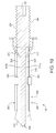
- FIG. 5 is a side view of the self-drilling anchor assembly of FIG. 1 , and illustrating the anchor and the drill bit of the self-drilling anchor assembly after assembly.
- FIG. 6 is a top view of the self-drilling anchor assembly of FIG. 1 , and illustrating the anchor and the drill bit of the self-drilling anchor assembly after assembly.
- FIG. 7 is a rear end view of the self-drilling anchor assembly of FIG. 1 , and illustrating the anchor and the drill bit of the self-drilling anchor assembly after assembly.
- FIG. 8 is a front end view of the self-drilling anchor assembly of FIG. 1 , and illustrating the anchor and the drill bit of the self-drilling anchor assembly after assembly.
- FIG. 9 is a cross-sectional view of the self-drilling anchor assembly of FIG. 1 , illustrating the anchor and the drill bit of the self-drilling anchor assembly after assembly, and taken substantially through line 9 - 9 of FIG. 5 .
- FIG. 10 is a cross-sectional view of the self-drilling anchor assembly of FIG. 1 , illustrating the anchor and the drill bit of the self-drilling anchor assembly after assembly, and taken substantially through line 10 - 10 of FIG. 5 .
- FIG. 11 is a side view of a drill (shown in fragmentary) rotating the self-drilling anchor assembly of FIG. 1 to form a hole in an example concrete wall substrate (shown in cross-section).
- FIG. 12 is a side view of the self-drilling anchor assembly of FIG. 1 positioned in the hole formed in the example concrete wall substrate (shown in cross-section), and with a fixture mounted on the tail of the drill bit.
- FIG. 13 is a side view of the self-drilling anchor assembly in the hole formed in the example concrete wall substrate (shown in cross-section), and with a washer and nut attached to the tail of the drill bit and securing the fixture to the concrete wall substrate (shown in cross-section).
- FIG. 14 is an exploded perspective view of a self-drilling anchor assembly of another example embodiment of the present disclosure, and illustrating the anchor and the drill bit of the self-drilling anchor assembly prior to assembly.
- FIG. 15 is a perspective view of the self-drilling anchor assembly of FIG. 14 , and illustrating the anchor and the drill bit of the self-drilling anchor assembly after assembly.
- FIG. 16 is an exploded perspective view of a self-drilling anchor assembly of another example embodiment of the present disclosure, and illustrating the anchor and the drill bit of the self-drilling anchor assembly prior to assembly.
- FIG. 17 is an exploded side view of the self-drilling anchor assembly of FIG. 16 , and illustrating the anchor and the drill bit of the self-drilling anchor assembly prior to assembly.
- FIG. 18 is an exploded top view of the self-drilling anchor assembly of FIG. 16 , and illustrating the anchor and the drill bit of the self-drilling anchor assembly prior to assembly.
- FIG. 19 is a perspective view of the self-drilling anchor assembly of FIG. 16 , and illustrating the anchor and the drill bit of the self-drilling anchor assembly after assembly.
- FIG. 20 is an exploded perspective view of a self-drilling anchor assembly of another example embodiment of the present disclosure, and illustrating the anchor and the drill bit of the self-drilling anchor assembly prior to assembly.
- FIG. 21 is a perspective view of the self-drilling anchor assembly of FIG. 20 , and illustrating the anchor and the drill bit of the self-drilling anchor assembly after assembly.
- FIG. 22 is an exploded perspective view of a self-drilling anchor assembly of another example embodiment of the present disclosure, and illustrating the anchor and the drill bit of the self-drilling anchor assembly prior to assembly.
- FIG. 23 is an exploded side view of the self-drilling anchor assembly of FIG. 22 , and illustrating the anchor and the drill bit of the self-drilling anchor assembly prior to assembly.
- FIG. 24 is an exploded top view of the self-drilling anchor assembly of FIG. 22 , and illustrating the anchor and the drill bit of the self-drilling anchor assembly prior to assembly.
- FIG. 25 is a perspective view of the self-drilling anchor assembly of FIG. 22 , and illustrating the anchor and the drill bit of the self-drilling anchor assembly after assembly.
- FIG. 25A is a perspective view of an alternative embodiment of the anchor of the self-drilling anchor assembly.
- FIG. 26 is an exploded perspective view of a self-drilling anchor assembly of another example embodiment of the present disclosure, and illustrating the anchor and the drill bit of the self-drilling anchor assembly prior to assembly.
- FIG. 27 is an exploded side view of the self-drilling anchor assembly of FIG. 26 , and illustrating the anchor and the drill bit of the self-drilling anchor assembly prior to assembly.
- FIG. 28 is an exploded top view of the self-drilling anchor assembly of FIG. 26 , and illustrating the anchor and the drill bit of the self-drilling anchor assembly prior to assembly.
- FIG. 29 is a perspective view of the self-drilling anchor assembly of FIG. 26 , and illustrating the anchor and the drill bit of the self-drilling anchor assembly after assembly.
- FIG. 30 is a first side perspective view of a drill bit of a self-drilling anchor assembly of another example embodiment of the present disclosure.
- FIG. 31 is a second side perspective view of the drill bit of FIG. 30 .
- FIG. 32 is a top view of the drill bit of FIG. 30 .
- FIG. 33 is a first side view of the drill bit of FIG. 30 .
- FIG. 34 is a bottom view of the drill bit of FIG. 30 .
- FIG. 35 is a second side view of the drill bit of FIG. 30 .
- FIG. 36 is a first side perspective view of a drill bit of a self-drilling anchor assembly of another example embodiment of the present disclosure.
- FIG. 37 is a first side view of the drill bit of FIG. 36 , the second side being a mirror image thereof.
- FIG. 38 is a top view of the drill bit of FIG. 36 , the bottom view being a mirror image thereof.
- FIG. 39 is a front end view of the drill bit of FIG. 36 .
- FIG. 40 is a rear end view of the drill bit of FIG. 36 .
- FIG. 41 is a first side perspective view of a drill bit of a self-drilling anchor assembly of another example embodiment of the present disclosure.
- FIG. 42 is a first side view of the drill bit of FIG. 41 , the second side being a mirror image thereof.
- FIG. 43 is a top view of the drill bit of FIG. 41 , the bottom view being a mirror image thereof.
- FIG. 44 is a front end view of the drill bit of FIG. 41 .
- FIG. 45 is a rear end view of the drill bit of FIG. 41 .
- FIG. 46 is a first side perspective view of a drill bit of a self-drilling anchor assembly of another example embodiment of the present disclosure.
- FIG. 47 is a first side view of the drill bit of FIG. 46 , the second side being a mirror image thereof.
- FIG. 48 is a top view of the drill bit of FIG. 46 , the bottom view being a mirror image thereof.
- FIG. 49 is a front end view of the drill bit of FIG. 46 .
- FIG. 50 is a rear end view of the drill bit of FIG. 46 .
- the present disclosure provides a self-drilling anchor assembly and a method of installing the self-drilling anchor assembly.
- the self-drilling anchor assembly includes: (a) a drill bit; and (b) an anchor positionable on or over and attached to the drill bit such that the when the drill bit rotates, the anchor rotates with the drill bit.
- the anchor is attached to the drill bit both axially and laterally (or transversely) by one or more attachment portions, tabs, or other such members.
- the anchor is attached to the drill bit laterally (or transversely) by one or more attachment portions, tabs, or other such members.
- the self-drilling anchor assembly includes: (a) a drill bit; and (b) an anchor positionable on or over and attached to the drill bit such that when the drill bit rotates, the anchor does not rotate with the drill bit (or can independently rotate).
- the anchor is attached to the drill bit axially (but not laterally or transversely) by one or more attachment portions, tabs, or other such members.
- the attachment of the anchor to the drill bit causes the anchor to move axially with the drill bit such as when the drill bit drills a hole and moves into a substrate, the anchor moves into the hole with the drill bit.
- Certain embodiments of the present disclosure thus take into account that during the drilling process, the anchor will likely come in contact with the wall of the hole being created by the drill bit. This may cause the anchor to bind in the hole from friction and effectively stop rotating while the drill bit is still spinning (and drilling).
- the axially attachment enables the anchor to remain attached to the drill bit in such instances and enables advancement of the drill bit and anchor into the hole even when the anchor stops rotating.
- the various embodiments of the present disclosure include or define one or more flutes, openings, or other debris expelling mechanisms that enable, facilitate, or allow the expelling of debris as the drill bit drills the hole in the substrate.
- These flutes, openings, or other debris expelling mechanisms are configured in the drill bit and/or the anchor to act individually and/or to co-act to enable, facilitate, or allow the expelling of debris as the drill bit drills the hole in the substrate (when both the drill bit and the anchor are rotating or when just the drill bit is rotating).
- the quantity, shape, and sizes of each of these one or more flutes, openings, and other debris expelling mechanisms may vary in accordance with the present disclosure.
- the self-drilling anchor assembly of this illustrated example embodiment is generally indicated by numeral 100 .
- the self-drilling anchor assembly 100 generally includes: (a) a drill bit 200 ; and (b) an anchor 300 positionable on or over and attached to the drill bit 200 .
- FIGS. 1, 2, and 3 show the self-drilling anchor assembly 100 and specifically the drill bit 200 and the anchor 300 before assembly.
- FIGS. 4 to 10 show the self-drilling anchor assembly 100 and specifically the drill bit 200 and the anchor 300 after assembly wherein: (a) the anchor is positioned on or over and attached to the drill bit 200 ; and (b) the drill bit 200 is partially positioned in and extends at both front and rear ends from the anchor 300 .
- FIGS. 11, 12, and 13 show the assembled self-drilling anchor assembly 100 being used to drill a hole in a substrate and to attach a fixture to the substrate as further described below.
- the drill bit 200 includes: (a) a generally cylindrical solid shank 210 having a front end 212 , an intermediate or center portion 214 , and a rear end 216 ; (b) a drill head 240 integrally connected to and extending from the front end 212 of the shank 210 ; and (c) an exterior threaded tail 260 integrally connected to and extending from the rear end 216 of the shank 210 .
- the drill bit 200 and specifically the shank 210 , the drill head 240 , and the tail 260 have a generally central longitudinal axis labeled A 1 .
- the drill bit 200 is configured to remain in the substrate and assist in maintaining the anchor 300 in the substrate as further explained below.
- the shank 210 includes an outer surface 211 that includes two recessed sections 211 a and 211 b that respectively define two opposing longitudinally extending flutes 220 and 224 that each extend longitudinally along the entire length of the shank 210 .
- the flutes 220 and 224 each have a generally semi-cylindrical cross section (at each point along the longitudinal length) and are configured to direct debris such as loose material of the substrate that is broken away by the drill head 240 from the drill head 240 toward the rear end 216 of the shank 210 and out of the hole being formed in the substrate as generally illustrated in FIG. 11 .
- the shank 210 may be alternatively configured (in shape and/or size) in accordance with the present disclosure.
- the drill head 240 includes a solid body 242 having a tip end 244 , an intermediate or center portion 246 , and a rear end 248 .
- the rear end 248 is integrally connected to and extends from the front end 212 of the shank 210 .
- the intermediate or center portion 246 has a generally wider outer diameter than the tip end 244 and the rear end 248 .
- the body 242 includes an outer surface 243 that includes two recessed sections 243 a and 243 b that respectively define two opposing longitudinally extending flutes 250 and 252 that each extend longitudinally along a portion of the body 242 toward the shank 210 .
- the flutes 250 and 252 each have a semi-cylindrical cross section and are configured to direct loose material of the substrate (that is broken away by the tip end 244 ) toward the front end 212 of the shank 210 and out of the hole being formed in the substrate as generally illustrated in FIG. 11 .
- the flutes 250 and 252 are respectively aligned with and are configured to communicate loose material to the flutes 220 and 224 defined by the shank 210 .
- each of the flutes 250 and 252 are relatively wider toward the tip end 244 and are narrower at or taper to the rear end 248 of the body 242 .
- each of the flutes 250 and 252 has the same or substantially the same cross-sectional area as the respective flutes 220 and 224 defined by the shank 210 as best shown by FIGS. 1 and 2 .
- the tip end 244 has a pointed drill tip 245 that is positioned at or along the central longitudinal axis A 1 .
- the tip end 244 includes two front outwardly and rearwardly extending angled cutting edges 253 a and 253 b that extend from the tip 245 .
- the tip end 244 includes a first side portion that includes a cutting surface 254 that extends rearwardly and outwardly from the cutting edges 253 a and 253 b to the section 243 a of the surface 243 of the drill head 240 that defines the flute 250 .
- the tip end 244 includes a second side portion that includes a first cutting surface 255 that extends rearwardly and outwardly from the cutting edges 253 a and 253 b to a second cutting surface 256 that in turn extends rearwardly to two spaced apart cutting surfaces 257 a and 257 b that in turn extend outwardly to the section 243 b of the surface 243 of the drill head 240 that defines the flute 252 .
- drill head of any of the various embodiments may be alternatively configured (in shape, surfaces, angles, and/or size) in accordance with the present disclosure.
- the threaded tail 260 includes a generally cylindrical body 262 having a front end 264 , an intermediate or center portion 266 , and a rear end 268 .
- the front end 264 is integrally connected to and extends from the rear end 216 of the shank 210 .
- the threaded tail 260 includes an outer outwardly extending helical thread formation 280 to facilitate attachment of a securing device such as a nut 400 and a washer 500 to the threaded tail 260 of the drill bit 200 (as generally shown in FIG. 13 and as further discussed below).
- the external helical thread formation 280 of the tail has a plurality of spaced apart thread sections (not labeled) that have or form outer edges or crests (not labeled) and valleys (not labeled) between the crests.
- the outer diameter of the helical thread formation (sometimes called the crest diameter) is greater than the outer diameter of the shank body 210 in this illustrated example embodiment to facilitate attachment of the anchor 300 to the drill bit 200 as further discussed below.
- the threaded tail 260 includes an interior mechanical engaging structure 290 (as best seen in FIGS. 7 and 10 ) that is accessible from the rear end 268 of the body 262 .
- the mechanical engaging structure 290 is engageable by a suitable tool to rotate the drill bit 200 (as generally shown in FIG. 11 and as further discussed below).
- the mechanical engaging structure 290 includes a plurality of internal walls (not labeled) having a plurality of first surfaces (not labeled) that define a hexagonal shaped slot or receiving formation configured to receive a hex head of or attached to a rotating tool such that the hex head can engage these respective first surfaces that define the hexagonal shaped slot.
- other mechanical engaging structures may be employed as the mechanical engaging structure of the tail in accordance with the present disclosure.
- the tail may be alternatively configured (in shape and/or size) in accordance with the present disclosure.
- the threads are on an inside surface of the tail of the drill bit and the mechanical engaging structure is on the outside surface of the tail of the drill bit.
- the thread formations may be left-handed (instead of right-handed as generally shown).
- the drill bit 200 is manufactured and specifically milled from a suitable steel material, such as Carbon steel material that is hardened and tempered, and plated and/or coated to resist corrosion.
- a suitable steel material such as Carbon steel material that is hardened and tempered, and plated and/or coated to resist corrosion.
- the drill bit can be made from other suitable materials and in other suitable manners.
- the drill bit does not need to be made from a relatively hard (or relatively expensive material) since the drill bit is configured to be used one time and to remain in the substrate as further described below.
- the anchor 300 includes: (i) an elongated generally tubular body 310 having an a front end 312 , an intermediate or center portion 314 , a rear end 316 , an outer surface 318 , and an inner surface 319 ; and (ii) a head 340 integrally connected to and extending from the rear end 316 of the tubular body 310 .
- the outer surface 318 of the body 310 has an outer diameter (not labeled); and (b) the inner surface 319 of the body 310 has an inner diameter (not labeled).
- the inner surface 319 of the tubular body 310 defines a longitudinally extending inner channel 320 configured to receive the drill bit 200 as generally shown in FIGS. 4 to 10 , and thus has a larger inner diameter than the outer diameter of the shank 210 of the drill bit 200 .
- the inner surface 319 of the tubular body 310 also has a larger inner diameter than the outer diameter of the tail 260 of the drill bit 200 .
- the inner surface 319 of the tubular body 310 has a smaller inner diameter than the outer diameter of the rear end 248 of the drill head 240 of the drill bit 200 .
- the body 310 has a generally central longitudinal axis labeled A 2 that is aligned with or that extends along the same central longitudinal axis AI of the drill bit 200 when the drill bit 200 is positioned in the anchor 300 .
- the front end 312 , the intermediate or center portion 314 , and the rear end 316 of the body 310 of the anchor 300 define, form, or include two independently movable or pivotable longitudinally extending opposing gripping arms 350 and 360 .
- the gripping arm 350 includes a longitudinally extending curved wall 351 and two drill bit attachment members or tabs 352 and 354 integrally connected to and circumferentially extending from opposite sides of the curved wall 351 .
- the gripping arm 360 includes a longitudinally extending curved wall 361 and two drill bit attachment members or tabs 362 and 364 integrally connected to and circumferentially extending from opposite sides of the curved wall 361 . It should be appreciated that the quantity of these attachment members or tabs may vary in accordance with the present disclosure.
- the rear end 316 of the body 310 of the anchor 300 includes a cylindrical wall 317 that defines a longitudinally extending inner cylindrical channel (not labeled) that is aligned with and in communication with the longitudinally extending inner channel 320 of the body 310 .
- the rear end 316 of the body 310 of the anchor 300 includes two opposing drill bit attachment members or tabs 370 and 372 integrally connected to and longitudinally extending from opposite sides of the wall 317 . It should be appreciated that the quantity of these attachment members or tabs may vary in accordance with the present disclosure.
- the front end 312 , the intermediate or center portion 314 , and the rear end 316 of the body 310 (or of the gripping arms 350 and 360 ) also define two spaced apart opposing longitudinally extending openings 321 a and 321 b (labeled in FIG. 1 ) that are generally configured to respectively align with the flutes 220 and 250 and 224 and 252 to enable the materials of the substrate removed by the drill head 240 to move from these flutes through the anchor 300 and out of the hole being drilled in the substrate as generally shown in FIG. 11 .
- the gripping arms in this illustrated example embodiment are identical or substantially identical. It should be appreciated that in other embodiments of the present disclosure, the gripping arms do not need to be identical or substantially identical and that the quantity of gripping arms may vary.
- the head 340 of the anchor 300 includes a cylindrical wall 341 that includes an inner surface (not shown) that defines a longitudinally extending inner channel (not shown) that is aligned with and in communication with the longitudinally extending inner channel of the rear end 316 of the body 310 of the anchor 300 and that is aligned with and in communication with the longitudinally extending inner channel 320 of the body 310 .
- the head 340 also includes flanges 390 , 392 , 394 , and 396 that are integrally connected to and extend outwardly or transversely from the cylindrical wall 341 .
- the flanges 390 , 392 , 394 , and 396 of the head 340 of the anchor 300 have flat or generally flat inner engagement surfaces 390 a , 392 a , 394 a , and 396 a .
- These engagement surfaces 390 a , 392 a , 394 a , and 396 a are configured to engage an outer surface of a substrate such as outer surface 720 of substrate 700 as generally shown in FIGS. 12 and 13 .
- the head of the anchor may be alternatively configured in accordance with the present disclosure.
- the anchor 300 is made from Carbon steel, and plated and/or coated to resist corrosion.
- the anchor can be made from other suitable materials and in other suitable manners.
- FIGS. 1, 2, and 3 show the self-drilling anchor assembly 100 before assembly and FIGS. 4 to 10 show the self-drilling anchor assembly after assembly.
- the drill bit 200 and specifically the tail 260 of the drill bit 200 is inserted into the front end 312 of the body 310 of the anchor 300 and moved through the anchor 300 until the tail 260 extends out of the rear end 316 of the anchor 300 , and the rear end 248 of the head 240 engages or is adjacent to the front end 312 of the body 310 of the anchor 300 .
- the attachment members or tabs 352 and 354 are pushed or bent inwardly into the flute 220 such that they are closer to or such that they engage the recessed section 211 a that defines the flute 220 (as shown in FIGS. 4, 5, 8, 9, and 10 ).
- the attachment members or tabs 362 and 364 are pushed or bent inwardly into the flute 224 such that they are closer to or such that they engage the recessed section 211 b that defines the flute 224 (as shown in FIGS. 4, 5, 8, 9, and 10 ).
- the attachment member or tab 370 is pushed or bent inwardly into the flute 220 such that it closer to or such that it engages the recessed section 211 a that defines the flute 220 .
- the attachment member or tab 372 is pushed or bent inwardly into the flute 224 such that it closer to or such that it engages the recessed section 211 b that defines the flute 224 .
- the attachment members or tabs 352 , 354 , 362 , 364 , 370 , and 372 co-act to maintain the anchor 300 in the desired position around the drill bit 200 .
- the attachment members or tabs 352 , 354 , 362 , 364 , 370 , and 372 co-act to cause the anchor 300 to rotate with the drill bit 200 when the drill bit 200 is rotated.
- the attachment members or tabs 370 and 372 co-act to prevent the drill bit 200 from exiting the anchor 310 because they are configured to engage the front end 264 of the body 262 of the tail 260 .
- the attachment members or tabs 370 and 372 also co-act with the respective flutes 220 and 224 to direct loose material out of the flutes and through the respective openings 321 a and 321 b in the anchor 300 and out of the hole being drilled in the substrate.
- the attachment members or tabs 370 and 372 are respectively positioned at downwardly extending angles as best shown in FIGS. 4, 6, and 10 .
- the attachment members or tabs 352 , 354 , 362 , 364 , 370 , and 372 co-act to facilitate certain amounts of desired movement between the drill bit 200 and the anchor 300 .
- the attachment members or tabs can be alternatively configured, alternatively positioned, and that quantity of attachments members or tabs can vary in accordance with the present disclosure.
- FIGS. 11, 12, and 13 One example method of the present disclosure of using the above described example anchor assembly 100 to attach a fixture to a substrate is generally illustrated in FIGS. 11, 12, and 13 .
- This example uses a metal member 600 as the fixture and a concrete wall 700 as the substrate; although it should be appreciated that the methods of the present disclosure are not limited to such example fixtures and such example substrates.
- the installer positions the assembled anchor assembly 100 against the concrete wall 700 at the desired positioned of the anchor assembly 100 and uses a drill 800 and engaging structure 850 to rotate the drill bit 200 to drill a hole 750 in the concrete wall 700 .
- the installer removably positions the engaging structure 850 in the mechanical engaging structure 290 .
- the entire anchor assembly 100 extends into the hole 750 in the concrete wall 700 .
- the loose material of the substrate exits the hole 750 by moving from the flutes 250 and 252 defined by the drill head 240 to the flutes 220 and 224 defined by the shank 210 and through the openings 321 a and 321 b defined by the body 310 of the anchor 300 .
- the inner surfaces 390 a , 392 a , 394 a , and 396 a of the respective flanges 390 , 392 , 394 , and 396 of the head 340 of the anchor 300 engage the outer surface 720 of the concrete wall 700 .
- the installer has removed the engaging structure 850 from the mechanical engaging structure 290 .
- a designated amount or length of the threaded tail 260 of the drill bit 200 partially extends outwardly from the concrete wall 700 as shown in FIG. 12 .
- the fixture 600 can be placed on the tail 260 of the drill bit.
- the washer 500 and the nut 400 are then place on the tail 260 of the drill bit 200 .
- the tightening of the nut 400 starts to draw the drill bit 200 out of the hole 750 .
- the drill head 240 causes the gripping arms 350 and 360 to expand or move outwardly and engage the inner surfaces that define the hole 750 to cause the anchor 300 to frictionally engage the substrate 700 to secure the anchor assembly 100 in the substrate 700 .
- the angled surfaces of the intermediate portion 246 of the drill head 240 of the drill bit 200 engage the inner surface 319 of the body 310 or of the gripping arms 350 and 360 and causes the outer surface 318 of the body 310 or of the gripping arms 350 and 360 to engage the inner surfaces that define the hole 750 to cause the anchor 300 to frictionally engage the substrate 700 to secure the anchor assembly 100 in the substrate 700 .
- the drill bit 200 remains as part of the anchor assembly 100 in the substrate 700 . It should further be appreciated as mentioned above, that the drill bit 200 will thus be typically only used one time and can be made from a relatively inexpensive material because wearing or dulling of the cutting tip and edges of the drill bit will not be a problem.
- the anchor assembly and the method of installing the anchor assembly of the present disclosure saves the installer a significant amount of time because it combines the two steps of drilling the hole and inserting the anchor.
- the present disclosure includes or provides the combination of the drill bit and the anchor (i.e., the anchor assembly), the drill bit itself, and the anchor itself.
- the present disclosure further provides a self-drilling anchor assembly and a method of installing the self-drilling anchor assembly.
- FIGS. 14 and 15 another example embodiment of a self-drilling anchor assembly of the present disclosure is generally illustrated.
- the self-drilling anchor assembly of this illustrated example embodiment is generally indicated by numeral 1100 .
- the self-drilling anchor assembly 1100 generally includes: (a) a drill bit 1200 ; and (b) an anchor 1300 positionable on or over and attached to the drill bit 1200 .
- FIG. 14 shows the self-drilling anchor assembly 1100 and specifically the drill bit 1200 and the anchor 1300 before assembly.
- FIG. 14 shows the self-drilling anchor assembly 1100 and specifically the drill bit 1200 and the anchor 1300 before assembly.
- FIG. 15 shows the self-drilling anchor assembly 1100 and specifically the drill bit 1200 and the anchor 1300 after assembly wherein: (a) the anchor 1300 is positioned on or over and attached to the drill bit 1200 ; and (b) the drill bit 1200 is partially positioned in and extends at both front and rear ends from the anchor 1300 .
- the drill bit 1200 is identical or substantially identical to the drill bit 200 (described above), and will thus only be generally described.
- the drill bit 1200 includes: (a) a generally cylindrical solid shank 1210 having a front end 1212 , an intermediate or center portion 1214 , and a rear end 1216 ; (b) a drill head 1240 integrally connected to and extending from the front end 1212 of the shank 1210 ; and (c) an exterior threaded tail 1260 integrally connected to and extending from the rear end 1216 of the shank 1210 .
- the shank 1210 has an outer surface 1211 that includes two recessed sections (including a first recessed section 1211 a and a second recessed section (not shown or labeled in FIG.
- the drill head 1240 includes a solid body 1242 having a tip end 1244 , an intermediate or center portion 1246 , and a rear end 1248 .
- the rear end 1248 is integrally connected to and extends from the front end 1212 of the shank 1210 .
- the intermediate or center portion 1246 has a generally wider outer diameter than the tip end 1244 and the rear end 1248 .
- the body 1242 has an outer surface 1243 that includes two recessed sections (including a first recessed section 1243 a and a second recessed section (not shown or labeled in FIG. 14 or 15 )) that respectively define two opposing longitudinally extending flutes (including a first flute 1250 and a second flute (not shown or labeled in FIG.
- each of the flutes are relatively wider toward the tip end 1244 and are narrower at or taper to the rear end 1248 of the body 1242 .
- each of the flutes has the same or substantially the same cross-sectional area as the respective flutes defined by the shank 1210 .
- the tip end 1244 has a pointed drill tip 1245 that is positioned at or along the central longitudinal axis.
- the tip end 1244 includes two front outwardly and rearwardly extending angled cutting edges 1253 a and 1253 b that extend from the tip 1245 .
- the tip end 1244 includes a first side portion that includes a cutting surface 1254 that extends rearwardly and outwardly from the cutting edges 1253 a and 1253 b to the section 1243 a of the surface 1243 of the drill head 1240 that defines the flute 1250 .
- the tip end 1244 includes a second side portion (not shown or labeled in FIG. 14 or 15 ) that includes a first cutting surface (not shown or labeled in FIG. 14 or 15 ) that extends rearwardly and outwardly from the cutting edges 1253 a and 1253 b to a second cutting surface (not shown or labeled in FIG. 14 or 15 ) that in turn extends rearwardly to two spaced apart cutting surfaces (not shown or labeled in FIG. 14 or 15 ).
- the threaded tail 1260 includes a generally cylindrical body 1262 having a front end 1264 , an intermediate or center portion 1266 , and a rear end 1268 .
- the front end 1264 is integrally connected to and extends from the rear end 1216 of the shank 1210 .
- the threaded tail 1260 includes an outer outwardly extending helical thread formation 1280 to facilitate attachment of a securing device such as a nut (not shown or labeled in FIG. 14 or 15 ) and a washer (not shown or labeled in FIG. 14 or 15 ) to the threaded tail 1260 of the drill bit 1200 .
- the threaded tail 1260 includes an interior mechanical engaging structure (not shown or labeled in FIG. 14 or 15 ) that is accessible from the rear end 1268 of the body 1262 .
- the mechanical engaging structure is engageable by a suitable tool to rotate the drill bit 1200 .
- the drill bit 1200 is manufactured and specifically milled from a suitable steel material, such as Carbon steel material that is hardened and tempered, and plated and/or coated to resist corrosion.
- a suitable steel material such as Carbon steel material that is hardened and tempered, and plated and/or coated to resist corrosion.
- the drill bit can be made from other suitable materials and in other suitable manners.
- the drill bit does not need to be made from a relatively hard (or relatively expensive material) since the drill bit is configured to be used one time and to remain in the substrate.
- the anchor 1300 is somewhat similar to the anchor 300 (described above), but includes certain alternatively configured parts.
- the anchor 1300 includes: (i) an elongated generally tubular body 1310 having an a front end 1312 , an intermediate or center portion 1314 , a rear end 1316 , an outer surface 1318 , and an inner surface 1319 ; and (ii) a head 1340 integrally connected to and extending from the rear end 1316 of the tubular body 1310 .
- the outer surface 1318 of the body 1310 has an outer diameter (not labeled); and (b) the inner surface 1319 of the body 1310 has an inner diameter (not labeled).
- the inner surface 1319 of the tubular body 1310 defines a longitudinally extending inner channel 1320 configured to receive the drill bit 1200 and thus has a larger inner diameter than the outer diameter of the shank 1210 of the drill bit 1200 .
- the inner surface 1319 of the tubular body 1310 also has a larger inner diameter than the outer diameter of the tail 1260 of the drill bit 1200 .
- the inner surface 1319 of the tubular body 1310 has a smaller inner diameter than the outer diameter of the rear end 1248 of the drill head 1240 of the drill bit 1200 .
- the body 1310 has a generally central longitudinal axis that is aligned with or that extends along the same central longitudinal axis of the drill bit 1200 when the drill bit 1200 is positioned in the anchor 1300 .
- the front end 1312 , the intermediate or center portion 1314 , and the rear end 1316 of the body 1310 of the anchor 1300 define, form, or include two independently movable or pivotable longitudinally extending opposing gripping arms 1350 and 1360 .
- the gripping arm 1350 includes a longitudinally extending curved wall 1351 and four drill bit attachment members or tabs 1352 a , 1352 b , 1354 a , and 1354 b integrally connected to and circumferentially extending from opposite sides of the curved wall 1351 .
- the gripping arm 1360 includes a longitudinally extending curved wall 1361 and four drill bit attachment members or tabs 1362 a , 1362 b , 1364 a , and 1364 b integrally connected to and circumferentially extending from opposite sides of the curved wall 1361 . It should be appreciated that the quantity of these attachment members or tabs may vary in accordance with the present disclosure.
- the rear end 1316 of the body 1310 of the anchor 1300 includes a cylindrical wall 1317 that defines a longitudinally extending inner cylindrical channel (not labeled) that is aligned with and in communication with the longitudinally extending inner channel 1320 of the body 1310 .
- the front end 1312 , the intermediate or center portion 1314 , and the rear end 1316 of the body 1310 (or of the gripping arms 1350 and 1360 ) also define two spaced apart opposing longitudinally extending openings (not labeled in FIG. 14 or 15 ) that are generally configured to respectively align with the flutes of the drill bit 1200 to enable the materials of the substrate removed by the drill head 1240 to move from these flutes through the anchor 1300 and out of the hole being drilled in the substrate.
- the gripping arms 1350 and 1360 in this illustrated example embodiment are identical or substantially identical. It should be appreciated that in other embodiments of the present disclosure, the gripping arms do not need to be identical or substantially identical and that the quantity of gripping arms may vary.
- the head 1340 of the anchor 1300 includes a cylindrical wall 1341 that includes an inner surface (not labeled in FIG. 14 or 15 ) that defines a longitudinally extending inner channel (not labeled in FIG. 14 or 15 ) that is aligned with and in communication with the longitudinally extending inner channel of the rear end 1316 of the body 1310 of the anchor 1300 and that is aligned with and in communication with the longitudinally extending inner channel 1320 of the body 1310 .
- the head 1340 also includes flanges 1390 , 1392 , 1394 , and 1396 that are integrally connected to and extend outwardly or transversely from the cylindrical wall 1341 .
- the flanges 1390 , 1392 , 1394 , and 1396 of the head 1340 of the anchor 1300 have flat or generally flat inner engagement surfaces 1390 a , 1392 a , 1394 a , and 1396 a . These engagement surfaces 1390 a , 1392 a , 1394 a , and 1396 a are configured to engage an outer surface of a substrate. It should be appreciated that the head of the anchor may be alternatively configured in accordance with the present disclosure.
- the anchor 1300 is made from Carbon steel, and plated and/or coated to resist corrosion.
- the anchor can be made from other suitable materials and in other suitable manners.
- the drill bit 1200 and specifically the tail 1260 of the drill bit 1200 is inserted into the front end 1312 of the body 1310 of the anchor 1300 and moved through the anchor 1300 until the tail 1260 extends out of the rear end 1316 of the anchor 1300 , and the rear end 1248 of the head 1240 engages or is adjacent to the front end 1312 of the body 1310 of the anchor 1300 .
- the attachment members or tabs 1352 a , 1352 b , 1354 a , and 1354 b are pushed or bent inwardly into the respective flutes such that they are closer to or such that they engage the recessed sections that define the respective flutes (such as shown in FIG.
- attachment members or tabs 1362 a , 1362 b , 1364 a and 1364 b are pushed or bent inwardly into the respective flutes such that they are closer to or such that they engage the recessed sections that define the respective flutes.
- the attachment members or tabs 1352 a , 1352 b , 1354 a , 1354 b , 1362 a , 1362 b , 1364 a , and 1364 b co-act to maintain the anchor 1300 in the desired position around the drill bit 1200 .
- the attachment members or tabs 1352 a , 1352 b , 1354 a , 1354 b , 1362 a , 1362 b , 1364 a , and 1364 b co-act to cause the anchor 1300 to rotate with the drill bit 1200 when the drill bit 1200 is rotated.
- attachment members or tabs 1352 a , 1352 b , 1354 a , 1354 b , 1362 a , 1362 b , 1364 a , and 1364 b co-act to facilitate certain amounts of desired movement between the drill bit 1200 and the anchor 1300 . It should further be appreciated that the attachment members or tabs can be alternatively configured, alternatively positioned, and that quantity of attachments members or tabs can vary in accordance with the present disclosure.
- the method of using the above described example anchor assembly 1100 is the same or substantially the same as the above described method generally shown in FIGS. 11, 12, and 13 , and thus will not be further described herein.
- the drill bit 1200 remains as part of the anchor assembly 1100 in the substrate. It should further be appreciated as mentioned above, that the drill bit 1200 will thus be typically only used one time and can be made from a relatively inexpensive material because wearing or dulling of the cutting tip and edges of the drill bit will not be a problem.
- FIGS. 16, 17, 18, and 19 another example embodiment of a self-drilling anchor assembly of the present disclosure is generally illustrated.
- the self-drilling anchor assembly of this illustrated example embodiment is generally indicated by numeral 2100 .
- the self-drilling anchor assembly 2100 generally includes: (a) a drill bit 2200 ; and (b) an anchor 2300 positionable on or over and attached to the drill bit 2200 .
- FIGS. 16, 17, and 18 show the self-drilling anchor assembly 2100 and specifically the drill bit 2200 and the anchor 2300 before assembly.
- FIG. 19 shows the self-drilling anchor assembly 2100 and specifically the drill bit 2200 and the anchor 2300 after assembly wherein: (a) the anchor 2300 is positioned on or over and attached to the drill bit 2200 ; and (b) the drill bit 2200 is partially positioned in and extends at both front and rear ends from the anchor 2300 .
- the drill bit 2200 is identical or substantially identical to the drill bit 200 (described above), and will thus only be generally described.
- the drill bit 2200 includes: (a) a generally cylindrical solid shank 2210 having a front end 2212 , an intermediate or center portion 2214 , and a rear end 2216 ; (b) a drill head 2240 integrally connected to and extending from the front end 2212 of the shank 2210 ; and (c) an exterior threaded tail 2260 integrally connected to and extending from the rear end 2216 of the shank 2210 .
- the shank 2210 has an outer surface 2211 that includes two recessed sections (including a first recessed section 2211 a and a second recessed section (not shown or labeled in FIG.
- the drill head 2240 includes a solid body 2242 having a tip end 2244 , an intermediate or center portion 2246 , and a rear end 2248 .
- the rear end 2248 is integrally connected to and extends from the front end 2212 of the shank 2210 .
- the intermediate or center portion 2246 has a generally wider outer diameter than the tip end 2244 and the rear end 2248 .
- the body 2242 has an outer surface 2243 that includes two recessed sections (including a first recessed section 2243 a and a second recessed section (not shown or labeled in FIG. 16, 17, 18 , or 19 )) that respectively define two opposing longitudinally extending flutes (including a first flute 2250 and a second flute (not shown or labeled in FIG.
- each of the flutes are relatively wider toward the tip end 2244 and are narrower at or taper to the rear end 2248 of the body 2242 .
- each of the flutes has the same or substantially the same cross-sectional area as the respective flutes defined by the shank 2210 .
- the tip end 2244 has a pointed drill tip 2245 that is positioned at or along the central longitudinal axis.
- the tip end 2244 includes two front outwardly and rearwardly extending angled cutting edges 2253 a and 2253 b that extend from the tip 2245 .
- the tip end 2244 includes a first side portion that includes a cutting surface 2254 that extends rearwardly and outwardly from the cutting edges 2253 a and 2253 b to the section 2243 a of the surface 2243 of the drill head 2240 that defines the flute 2250 .
- the tip end 2244 includes a second side portion that includes a first cutting surface 2255 that extends rearwardly and outwardly from the cutting edges 2253 a and 2253 b to a second cutting surface 2256 that in turn extends rearwardly to two spaced apart cutting surfaces (including cutting surface 2257 ).
- the threaded tail 2260 includes a generally cylindrical body 2262 having a front end 2264 , an intermediate or center portion 2266 , and a rear end 2268 .
- the front end 2264 is integrally connected to and extends from the rear end 2216 of the shank 2210 .
- the threaded tail 2260 includes an outer outwardly extending helical thread formation 2280 to facilitate attachment of a securing device such as a nut (not shown or labeled in FIG. 16, 17, 18 , or 19 ) and a washer (not shown or labeled in FIG. 16, 17, 18 , or 19 ) to the threaded tail 2260 of the drill bit 2200 .
- the threaded tail 2260 includes an interior mechanical engaging structure (not shown or labeled in FIG. 16, 17, 18 , or 19 ) that is accessible from the rear end 2268 of the body 2262 .
- the mechanical engaging structure is engageable by a suitable tool to rotate the drill bit 2200 .
- the drill bit 2200 is manufactured and specifically milled from a suitable steel material, such as Carbon steel material that is hardened and tempered, and plated and/or coated to resist corrosion.
- a suitable steel material such as Carbon steel material that is hardened and tempered, and plated and/or coated to resist corrosion.
- the drill bit can be made from other suitable materials and in other suitable manners.
- the drill bit does not need to be made from a relatively hard (or relatively expensive material) since the drill bit is configured to be used one time and to remain in the substrate as further described below.
- the anchor 2300 includes: (i) an elongated generally tubular body 2310 having a front end 2312 , an intermediate or center portion 2314 , a rear end 2316 , an outer surface 2318 , and an inner surface 2319 ; and (ii) a head 2340 integrally connected to and extending from the rear end 2316 of the tubular body 2310 .
- the outer surface 2318 of the body 2310 has an outer diameter (not labeled); and (b) the inner surface 2319 of the body 2310 has an inner diameter (not labeled).
- the inner surface 2319 of the tubular body 2310 defines a longitudinally extending inner channel 2320 configured to receive the drill bit 2200 , and thus has a larger inner diameter than the outer diameter of the shank 2210 of the drill bit 2200 .
- the inner surface 2319 of the tubular body 2310 also has a larger inner diameter than the outer diameter of the tail 2260 of the drill bit 2200 .
- the inner surface 2319 of the tubular body 2310 has a smaller inner diameter than the outer diameter of the rear end 2248 of the drill head 2240 of the drill bit 2200 .
- the body 2310 has a generally central longitudinal axis that is aligned with or that extends along the same central longitudinal axis of the drill bit 2200 when the drill bit 2200 is positioned in the anchor 2300 .
- the front end 2312 and the intermediate or center portion 2314 of the body 2310 of the anchor 2300 define, form, or include four somewhat independently movable or pivotable longitudinally extending opposing gripping arms 2350 a , 2350 b , and 2360 a , and 2360 b .
- Gripping arm 2350 a includes a longitudinally extending curved wall 2351 a and an elongated drill bit attachment member or tab 2352 integrally connected to and circumferentially extending from one side of the curved wall 2351 a .
- Gripping arm 2350 b includes a longitudinally extending curved wall 2351 b and an elongated drill bit attachment member or tab 2354 integrally connected to and circumferentially extending from one side of the curved wall 2351 b .
- Gripping arms 2350 a and 2350 b extend from a first part of the intermediate or center portion 2314 and end portion 2316 of the body 2310 of the anchor 2300 .
- Gripping arm 2360 a includes a longitudinally extending curved wall 2361 a and an elongated drill bit attachment member or tab 2362 integrally connected to and circumferentially extending from one side of the curved wall 2361 a .
- Gripping arm 2360 b includes a longitudinally extending curved wall 2361 b and an elongated drill bit attachment member or tab 2364 integrally connected to and circumferentially extending from one side of the curved wall 2361 b .
- Gripping arms 2360 a and 2360 b extend from a second part of the intermediate or center portion 2314 and end portion 2316 of the body 2310 of the anchor 2300 . It should be appreciated that the quantity of these attachment members or tabs may vary in accordance with the present disclosure.
- the rear end 2316 of the body 2310 of the anchor 2300 includes a partially cylindrical wall 2317 that defines a longitudinally extending inner cylindrical channel (not labeled) that is aligned with and in communication with the longitudinally extending inner channel 2320 of the body 2310 .
- the front end 2312 , the intermediate or center portion 2314 , and the rear end 2316 of the body 2310 also define two spaced apart opposing longitudinally extending openings 2321 a and 2321 b (labeled in FIG. 16 ) that are generally configured to respectively align with the flutes of the drill 2200 to enable the materials of the substrate removed by the drill head 2240 to move from these flutes through the anchor 2300 and out of the hole being drilled in the substrate.
- the gripping arms and the quantity of gripping arms may vary.
- the head 2340 of the anchor 2300 includes a cylindrical wall 2341 that includes an inner surface 2344 that defines a longitudinally extending inner channel 2348 that is aligned with and in communication with the longitudinally extending inner channel of the rear end 2316 of the body 2310 of the anchor 2300 and that is aligned with and in communication with the longitudinally extending inner channel 2320 of the body 2310 .
- the head 2340 also includes an outwardly extending annular flange 2390 that is integrally connected to and extends outwardly or transversely from the cylindrical wall 2341 .
- the annular flange 2390 of the head 2340 of the anchor 2300 has a flat or generally flat inner engagement surface 2390 a . This engagement surface 2390 a is configured to engage an outer surface of a substrate such as outer surface of substrate. It should be appreciated that the head of the anchor may be alternatively configured in accordance with the present disclosure.
- the anchor 2300 is made from Carbon steel, and plated and/or coated to resist corrosion. However, it should be appreciated that the anchor can be made from other suitable materials and in other suitable manners.
- the head 2340 of the anchor 2300 and particularly the cylindrical wall 2341 can be suitably attached (such as by welding) to the rear end 2316 of the body 2310 of the anchor 2300 during the manufacturing process for the anchor 2300 .
- the drill bit 2200 and specifically the tail 2260 of the drill bit 2200 is inserted into the front end 2312 of the body 2310 of the anchor 2300 and moved through the anchor 2300 until the tail 2260 extends out of the rear end of the anchor 2300 , and the rear end 2248 of the head 2240 engages or is adjacent to the front end 2312 of the body 2310 of the anchor 2300 .
- the elongated attachment members or tabs 2352 and 2362 are pushed or bent inwardly into the flute 2220 such that they are closer to or such that they engage the recessed section 2211 a that defines the flute 2220 .
- the elongated attachment members or tabs 2354 and 2364 are pushed or bent inwardly into the opposite flute (not labeled) of the drill bit 2200 such that they are closer to or such that they engage the recessed section that defines that flute.
- the attachment members or tabs 2352 , 2354 , 2362 and 2364 co-act to maintain the anchor 2300 in the desired position around the drill bit 2200 .
- the attachment members or tabs 2352 , 2354 , 2362 and 2364 co-act to cause the anchor 2300 to rotate with the drill bit 2200 when the drill bit 2200 is rotated.
- the attachment members or tabs 2352 , 2354 , 2362 and 2364 co-act to facilitate certain amounts of desired movement between the drill bit 2200 and the anchor 2300 .
- the attachment members or tabs can be alternatively configured, alternatively positioned, and that quantity of attachments members or tabs can vary in accordance with the present disclosure.
- the drill bit 2200 remains as part of the anchor assembly 2100 in the substrate. It should further be appreciated as mentioned above, that the drill bit 2200 will thus be typically only used one time and can be made from a relatively inexpensive material because wearing or dulling of the cutting tip and edges of the drill bit will not be a problem.
- FIGS. 20 and 21 another example embodiment of a self-drilling anchor assembly of the present disclosure is generally illustrated.
- the self-drilling anchor assembly of this illustrated example embodiment is generally indicated by numeral 3100 .
- the self-drilling anchor assembly 3100 generally includes: (a) a drill bit 3200 ; and (b) a two piece anchor 3300 positionable on or over and attached to the drill bit 3200 .
- FIG. 20 shows the self-drilling anchor assembly 3100 and specifically the drill bit 3200 and the anchor 3300 before assembly.
- FIG. 21 shows the self-drilling anchor assembly 3100 and specifically the drill bit 3200 and the anchor 3300 after assembly wherein: (a) the anchor 3300 is positioned on or over and attached to the drill bit 3200 ; and (b) the drill bit 3200 is partially positioned in and extends at both front and rear ends from the anchor 3300 .
- the drill bit 3200 is identical or substantially identical to the drill bit 200 (described above), and will thus only be generally described.
- the drill bit 3200 includes: (a) a generally cylindrical solid shank 3210 having a front end 3212 , an intermediate or center portion 3214 , and a rear end 3216 ; (b) a drill head 3240 integrally connected to and extending from the front end 3212 of the shank 3210 ; and (c) an exterior threaded tail 3260 integrally connected to and extending from the rear end 3216 of the shank 3210 .
- the shank 3210 has an outer surface 3211 that includes two recessed sections (including a first recessed section 3211 a and a second recessed section (not shown or labeled in FIG.
- the drill head 3240 includes a solid body 3242 having a tip end 3244 , an intermediate or center portion 3246 , and a rear end 3248 .
- the rear end 3248 is integrally connected to and extends from the front end 3212 of the shank 3210 .
- the intermediate or center portion 3246 has a generally wider outer diameter than the tip end 3244 and the rear end 3248 .
- the body 3242 has an outer surface 3243 that includes two recessed sections (including a first recessed section 3243 a and a second recessed section (not shown or labeled in FIG. 20 or 21 )) that respectively define two opposing longitudinally extending flutes (including a first flute 3250 and a second flute (not shown or labeled in FIG.
- each of the flutes are relatively wider toward the tip end 3244 and are narrower at or taper to the rear end 3248 of the body 3242 .
- each of the flutes has the same or substantially the same cross-sectional area as the respective flutes defined by the shank 3210 .
- the tip end 3244 has a pointed drill tip 3245 that is positioned at or along the central longitudinal axis.
- the tip end 3244 includes two front outwardly and rearwardly extending angled cutting edges 3253 a and 3253 b that extend from the tip 3245 .
- the tip end 3244 includes a first side portion that includes a cutting surface 3254 that extends rearwardly and outwardly from the cutting edges 3253 a and 3253 b to the section 3243 a of the surface 3243 of the drill head 3240 that defines the flute 3250 .
- the tip end 3244 includes a second side portion (not shown or labeled in FIG. 20 or 21 ) that includes a first cutting surface (not shown or labeled in FIG. 20 or 21 ) that extends rearwardly and outwardly from the cutting edges 3253 a and 3253 b to a second cutting surface (not shown or labeled in FIG. 20 or 21 ) that in turn extends rearwardly to two spaced apart cutting surfaces (not shown or labeled in FIG. 20 or 21 ) that extend outwardly.
- the threaded tail 3260 includes a generally cylindrical body 3262 having a front end 3264 , an intermediate or center portion 3266 , and a rear end 3268 .
- the front end 3264 is integrally connected to and extends from the rear end 3216 of the shank 3210 .
- the threaded tail 3260 includes an outer outwardly extending helical thread formation 3280 to facilitate attachment of a securing device such as a nut (not shown in FIG. 20 or 21 ) and a washer (not shown in FIG. 20 or 21 ) to the threaded tail 3260 of the drill bit 3200 .
- the threaded tail 3260 includes an interior mechanical engaging structure (not shown in FIG. 20 or 21 ) that is accessible from the rear end 3268 of the body 3262 . The mechanical engaging structure is engageable by a suitable tool to rotate the drill bit 3200 .
- the drill bit 3200 is manufactured and specifically milled from a suitable steel material, such as Carbon steel material that is hardened and tempered, and plated and/or coated to resist corrosion.
- a suitable steel material such as Carbon steel material that is hardened and tempered, and plated and/or coated to resist corrosion.
- the drill bit can be made from other suitable materials and in other suitable manners.
- the drill bit does not need to be made from a relatively hard (or relatively expensive material) since the drill bit is configured to be used one time and to remain in the substrate as further described below.
- the anchor 3300 is somewhat similar to the anchor 300 (described above), but it is formed from multiple portions, and particularly two halves. In various embodiments, the anchor 3300 is formed in this manner for ease of manufacturing purposes and for ease of assembly purposes. In particular, each half can be manufactured separately using a stamping and bending process. Additionally, during assembly, the opposing sides do not need to be placed over the threaded end of the drill bit 3200 and thus avoids damage to the threads of the drill bit 3200 .
- the anchor 3300 includes an elongated first portion 3302 and an elongated second portion 3304 that together form a generally tubular body 3310 having a front end 3312 , an intermediate or center portion 3314 , a rear end 3316 , an outer surface 3318 , and an inner surface 3319 .
- the elongated first portion 3302 and the elongated second portion 3304 also together form a head 3340 connected to and extending from the rear end 3316 of the tubular body 3310 .
- the outer surface 3318 of the body 3310 has an outer diameter (not labeled) and the inner surface 3319 of the body 3310 has an inner diameter (not labeled).
- the inner surface 3319 of the tubular body 3310 defines a longitudinally extending inner channel 3320 configured to receive the drill bit 3200 , and thus has a larger inner diameter than the outer diameter of the shank 3210 of the drill bit 3200 .
- the inner surface 3319 of the tubular body 3310 also has a larger inner diameter than the outer diameter of the tail 3260 of the drill bit 3200 .
- the inner surface 3319 of the tubular body 3310 has a smaller inner diameter than the outer diameter of the rear end 3248 of the drill head 3240 of the drill bit 3200 .
- the body 3310 has a generally central longitudinal axis that is aligned with or that extends along the same central longitudinal axis of the drill bit 3200 when the drill bit 3200 is positioned in the anchor 3300 .
- the front end 3312 , the intermediate or center portion 3314 , and the rear end 3316 of the body 3310 of the anchor 3300 define, form, or include two independently movable or pivotable longitudinally extending opposing gripping arms 3350 and 3360 .
- the first portion 3302 includes gripping arm 3350 and the second portion 3304 includes gripping arm 3360 .
- the gripping arm 3350 includes a longitudinally extending curved wall 3351 and two drill bit attachment members or tabs 3352 and 3354 integrally connected to and circumferentially extending from opposite sides of the curved wall 3351 .
- the gripping arm 3360 includes a longitudinally extending curved wall 3361 and two drill bit attachment members or tabs 3362 and 3364 integrally connected to and circumferentially extending from opposite sides of the curved wall 3361 . It should be appreciated that the quantity of these attachment members or tabs may vary in accordance with the present disclosure.
- the rear end 3316 of the body 3310 of the anchor 3300 When assembled, the rear end 3316 of the body 3310 of the anchor 3300 includes a cylindrical wall 3317 that defines a longitudinally extending inner cylindrical channel (not labeled) that is aligned with and in communication with the longitudinally extending inner channel 3320 of the body 3310 .
- the rear end 3316 of the body 3310 of the anchor 3300 includes two opposing drill bit attachment members or tabs 3370 and 3372 connected to and longitudinally extending from opposite sides of the cylindrical wall 3317 .
- the first portion 3302 includes drill bit attachment member or tab 3372 and the second portion 3304 includes drill bit attachment member or tab 3370 . It should be appreciated that the quantity of these attachment members or tabs may vary in accordance with the present disclosure.
- the front end 3312 , the intermediate or center portion 3314 , and the rear end 3316 of the body 3310 (or of the gripping arms 3350 and 3360 ) also define two spaced apart opposing longitudinally extending openings (best seen in FIG. 21 but not labeled) that are generally configured to respectively align with the flutes 3220 and 3250 and the flutes 3224 and 3252 (not shown) to enable the materials of the substrate removed by the drill head 3240 to move from these flutes through the anchor 3300 and out of the hole being drilled in the substrate.
- the gripping arms in this illustrated example embodiment are identical or substantially identical. It should be appreciated that in other embodiments of the present disclosure, the gripping arms do not need to be identical or substantially identical and that the quantity of gripping arms may vary.
- the head 3340 of the anchor 3300 When assembled, the head 3340 of the anchor 3300 includes a cylindrical wall 3341 that includes an inner surface 3344 that defines a longitudinally extending inner channel (not labeled) that is aligned with and in communication with the longitudinally extending inner channel of the rear end 3316 of the body 3310 of the anchor 3300 and that is aligned with and in communication with the longitudinally extending inner channel 3320 of the body 3310 .
- the head 3340 also includes outwardly extending flanges 3390 , 3392 , 3394 , and 3396 that are connected to and extend outwardly or transversely from the cylindrical wall 3341 .
- the first portion 3302 includes flanges 3392 and 3394 and the second portion 3304 includes flanges 3390 and 3396 .
- the flanges 3390 , 3392 , 3394 , and 3396 of the head 3340 of the anchor 3300 have flat or generally flat inner engagement surfaces 3390 a , 3392 a , 3394 a , and 3396 a .
- These engagement surfaces 3390 a , 3392 a , 3394 a , and 3396 a are configured to engage an outer surface of a substrate. It should be appreciated that the head of the anchor may be alternatively configured in accordance with the present disclosure.
- the anchor 3300 is made from Carbon steel, and plated and/or coated to resist corrosion.
- the anchor can be made from other suitable materials and in other suitable manners.
- the first portion 3302 and the second portion 3304 of the anchor are positioned on opposing sides around and over the central portion or shank 3210 of the drill bit 3200 such that the tail 3260 extends out of the rear end of the anchor 3300 , and the rear end 3248 of the head 3240 engages or is adjacent to the front end 3312 of the anchor 3300 .
- the attachment members or tabs 3352 and 3362 are pushed or bent inwardly into the flute 3220 such that they are closer to or such that they engage the recessed section 3211 a that defines the flute 3220 .
- the attachment members or tabs 3354 and 3364 are pushed or bent inwardly into the flute 3224 (not shown) such that they are closer to or such that they engage the recessed section that defines the flute 3224 .
- the attachment member or tab 3370 is pushed or bent inwardly into the flute 3220 such that it closer to or such that it engages the recessed section 3211 a that defines the flute 3220 .
- the attachment member or tab 3372 is pushed or bent inwardly into the flute 3224 such that it closer to or such that it engages the recessed section that defines the flute 3224 . It should be appreciated that this assembly process does not require assembly over the threaded portion of the drill bit 3200 and thus reduces the likelihood of any damage to the threads during the assembly process.
- the attachment members or tabs 3352 , 3354 , 3362 , 3364 , 3370 , and 3372 co-act to maintain the anchor 3300 in the desired position around the drill bit 3200 .
- the attachment members or tabs 3352 , 3354 , 3362 , 3364 , 33370 , and 3372 co-act to cause the anchor 3300 to rotate with the drill bit 200 when the drill bit 3200 is rotated.
- the attachment members or tabs 3370 and 3372 co-act to prevent the drill bit 3200 from exiting the anchor 3300 because they are configured to engage the front end 3264 of the body 3262 of the tail 3260 .
- the attachment members or tabs 3370 and 3372 also co-act with the respective flutes 3220 and 3224 to direct loose material out of the flutes and through the respective openings in the anchor 3300 and out of the hole being drilled in the substrate.
- the attachment members or tabs 3370 and 3372 are respectively positioned at downwardly extending angles.
- the attachment members or tabs 3352 , 3354 , 3362 , 3364 , 3370 , and 3372 co-act to facilitate certain amounts of desired movement between the drill bit 3200 and the anchor 3300 .
- the attachment members or tabs can be alternatively configured, alternatively positioned, and that quantity of attachments members or tabs can vary in accordance with the present disclosure.
- FIGS. 22, 23, 24, and 25 another example embodiment of a self-drilling anchor assembly of the present disclosure is generally illustrated.
- the self-drilling anchor assembly of this illustrated example embodiment is generally indicated by numeral 4100 .
- the self-drilling anchor assembly 4100 generally includes: (a) a drill bit 4200 ; and (b) an anchor 4300 positionable on or over and attached to the drill bit 4200 .
- FIGS. 22, 23, and 24 show the self-drilling anchor assembly 4100 and specifically the drill bit 4200 and the anchor 4300 before assembly.
- the anchor 4300 is axially attached to the drill bit 4200 such that when the drill bit 4200 rotates, the anchor 4300 does not rotate with the drill bit (or can independently rotate).
- the attachment of the anchor 4300 to the drill bit 4200 causes the anchor 4300 to move axially with the drill bit 4200 such as when the drill bit 4200 drills a hole and moves into a substrate, the anchor 4300 moves into the hole with the drill bit.
- this alternative example drill bit 4200 includes: (a) a generally cylindrical solid shank 4210 having a front end 4212 , an intermediate or center portion 4214 , and a rear end 4216 ; (b) a drill head 4240 integrally connected to and extending from the front end 4212 of the shank 4210 ; and (c) an exterior threaded tail 4260 integrally connected to and extending from the rear end 4216 of the shank 4210 .
- the drill bit 4200 and specifically the shank 4210 , the drill head 4240 , and the tail 4260 have a generally central longitudinal axis.
- the drill bit 4200 is configured to remain in the substrate and assist in maintaining the anchor 4300 in the substrate.
- the shank 4210 includes an outer surface 4211 that includes two recessed longitudinally extending sections (including section 4211 a ) that respectively define two opposing longitudinally extending flutes (including flute 4220 ) that each extend longitudinally along the entire length of the shank 4210 .
- the flutes each have a generally rectangular cross section (at each point along the longitudinal length) and are configured to direct loose material of the substrate that is broken away by the drill head 4240 from the drill head 4240 toward the rear end 4216 of the shank 4210 and out of the hole being formed in the substrate.
- the shank 4210 further includes a recessed circumferentially extending section 4213 a that defines an annular locking recess or groove 4215 configured to receive inwardly extending drill bit attachment portions 4358 a , 4358 b , and 4358 c , and 4358 d that form an inwardly extending drill bit attachment ring 4358 of the anchor 4300 .
- the shank 4210 may be alternatively configured (in shape and/or size) in accordance with the present disclosure.
- the drill head 4240 includes a solid body 4242 having a tip end 4244 , an intermediate or center portion 4246 , and a rear end 4248 .
- the rear end 4248 is integrally connected to and extends from the front end 4212 of the shank 4210 .
- the intermediate or center portion 4246 has a generally wider outer diameter than the tip end 4244 and the rear end 4248 .
- the body 4242 includes an outer surface 4243 that includes two recessed sections (including section 4243 a ) that respectively define two opposing longitudinally extending flutes (including flute 4250 ) each extending longitudinally along a portion of the body 4242 toward the shank 4210 .
- the flutes each have a rectangular cross section and are configured to direct loose material of the substrate (that is broken away by the tip end 4244 ) toward the front end 4212 of the shank 4210 and out of the hole being formed in the substrate.
- the flutes are respectively aligned with and are configured to communicate loose material to the flutes defined by the shank 4210 .
- the flutes are each of the same or substantially the same cross-sectional area as the respective flutes defined by the shank 4210 .
- the tip end 4244 has a pointed drill tip 4245 that is positioned at or along the central longitudinal axis.
- the tip end 4244 includes two front outwardly and rearwardly extending angled cutting edges 4253 a and 4253 b that extend from the tip 4245 .
- the tip end 4244 includes first side portions (not labeled) that each extend rearwardly and outwardly from the cutting edges 4253 a and 4253 b .
- the tip end 4244 also includes second side portions (not labeled) that each extend rearwardly and outwardly from the cutting edges 4253 a and 4253 b .
- the tip end 4244 further includes four rear outwardly and rearwardly extending angled additional cutting edges (not labeled).
- the tip end 4244 includes a first side portion (not labeled) that extends rearwardly and outwardly from the additional cutting edges.
- the tip end 4244 includes a second side portion (not labeled) that extends rearwardly and outwardly from the additional cutting edges.
- the drill head may be alternatively configured (in shape and/or size) in accordance with the present disclosure.
- the threaded tail 4260 includes a generally cylindrical body 4262 having a front end 4264 , an intermediate or center portion 4266 , and a rear end 4268 .
- the front end 4264 is integrally connected to and extends from the rear end 4216 of the shank 4210 .
- the threaded tail 4260 includes an outer outwardly extending helical thread formation 4280 to facilitate attachment of a securing device such as a nut 4990 and a washer 4980 to the threaded tail 4260 of the drill bit 4200 .
- the external helical thread formation 4280 of the tail 4260 has a plurality of spaced apart thread sections (not labeled) that have or form outer edges or crests (not labeled) and valleys (not labeled) between the crests.
- the outer diameter of the helical thread formation (sometimes called the crest diameter) is greater than the outer diameter of the shank body 4210 in this illustrated example embodiment to facilitate attachment of the anchor 4300 to the drill bit 4200 .
- the threaded tail 4260 includes an interior mechanical engaging structure (not shown or labeled) that is accessible from the rear end 4268 of the body 4262 .
- the mechanical engaging structure is engageable by a suitable tool to rotate the drill bit 4200 . It should be appreciated that in other embodiments of the present disclosure, other mechanical engaging structures may be employed as the mechanical engaging structure of the tail in accordance with the present disclosure.
- the drill bit 4200 is manufactured and specifically milled from a suitable steel material, such as Carbon steel material that is hardened and tempered, and plated and/or coated to resist corrosion.
- a suitable steel material such as Carbon steel material that is hardened and tempered, and plated and/or coated to resist corrosion.
- the drill bit can be made from other suitable materials and in other suitable manners.
- the drill bit does not need to be made from a relatively hard (or relatively expensive material) since the drill bit is configured to be used one time and to remain in the substrate as further described below.
- the anchor 4300 includes: (i) an elongated generally tubular body 4310 having an a front end 4312 , an intermediate or center portion 4314 , and a rear end 4316 , an outer surface 4318 , and an inner surface 4319 ; and (ii) a head 4340 integrally connected to and extending from the rear end 4316 of the tubular body 4310 .
- the outer surface 4318 of the body 4310 has an outer diameter (not labeled); and the inner surface 4319 of the body 4310 has an inner diameter (not labeled).
- the inner surface 4319 of the tubular body 4310 defines a longitudinally extending inner channel 4320 configured to receive the drill bit 4200 , and thus has a larger inner diameter than the outer diameter of the shank 4210 of the drill bit 4200 .
- the inner surface 4319 of the tubular body 4310 also has a larger inner diameter than the outer diameter of the tail 4260 of the drill bit 4200 .
- the body 4310 has a generally central longitudinal axis that is aligned with or that extends along the same central longitudinal axis of the drill bit 4200 when the drill bit 4200 is positioned in the anchor 4300 .
- the front end 4312 , the intermediate or center portion 4314 , and the rear end 4316 of the body 4300 of the anchor 4300 define, form, or include four independently movable or pivotable longitudinally extending angled and curved gripping arms 4350 a , 4350 b , 4360 a , and 4360 b .
- Gripping arm 4350 a includes a longitudinally extending curved wall 4351 a and a drill bit attachment portion 4358 a integrally connected to and extending inwardly from the curved wall 4351 a .
- Gripping arm 4350 b includes a longitudinally extending curved wall 4351 b and a drill bit attachment portion 4358 b integrally connected to and extending inwardly from the curved wall 4351 b .
- Gripping arm 4360 a includes a longitudinally extending curved wall 4361 a and a drill bit attachment portion 4358 c integrally connected to and extending inwardly from the curved wall 4361 a .
- Gripping arm 4360 b includes a longitudinally extending curved wall 4361 b and a drill bit attachment portion 4358 d integrally connected to and extending inwardly from the curved wall 4361 b .
- the gripping arms 4350 a , 4350 b , 4360 a , and 4360 b are curved or extend in a diagonal direction such that the openings or flutes formed between the gripping arms 4350 a , 4350 b , 4360 a , and 4360 b are curved or extend in a diagonal direction.
- the gripping arms in this illustrated example embodiment are identical or substantially identical. It should be appreciated that in other embodiments of the present disclosure, the gripping arms do not need to be identical or substantially identical and that the quantity of gripping arms may vary. It should also be appreciated that the attachment portions can co-act to form an engagement ring that extends into the annular groove in the drill bit such that the anchor remains attached to the drill bit even when the anchor is not rotating such as due to binding with the walls of the hole.
- the rear end 4316 of the body 4310 of the anchor 4300 includes a cylindrical wall 4317 that defines a longitudinally extending inner cylindrical channel (not labeled) that is aligned with and in communication with the longitudinally extending inner channel 4320 of the body 4310 .
- the head 4340 of the anchor 4300 includes a cylindrical wall 4341 that includes an inner surface (not labeled) that defines a longitudinally extending inner channel (not labeled) that is aligned with and in communication with the longitudinally extending inner channel of the rear end 4316 of the body 4310 of the anchor 4300 and that is aligned with and in communication with the longitudinally extending inner channel 4320 of the body 4310 .
- the head 4340 also includes flanges 4390 , 4392 , 4394 , and 4396 that are integrally connected to and extend outwardly or transversely from the cylindrical wall 4341 .
- the flanges 4390 , 4392 , 4394 , and 4396 of the head 4340 of the anchor 4300 have flat or generally flat inner engagement surfaces 4390 a , 4392 a , 4394 a , and 4396 a .
- These engagement surfaces 4390 a , 4392 a , 4394 a , and 4396 a are configured to engage an outer surface of a substrate. It should be appreciated that the head of the anchor may be alternatively configured in accordance with the present disclosure.
- the anchor 4300 is made from Carbon steel, and plated and/or coated to resist corrosion.
- the anchor can be made from other suitable materials and in other suitable manners.
- the drill bit 4200 and specifically the tail 4260 of the drill bit 4200 is inserted into the front end 4312 of the body 4310 of the anchor 4300 and moved through the anchor 4300 until the tail 4260 extends out of the rear end of the anchor 4300 , and the rear end 4248 of the head 4240 engages or is adjacent to the front end 4312 of the body 4310 of the anchor 4300 .
- the drill bit attachment portions 4358 a , 4358 b , 4358 c , and 4358 d extend into the annular locking recess as shown in FIG. 25 .
- the drill bit attachment portions 4358 a , 4358 b , 4358 c , and 4358 d (that form the drill bit attachment ring) co-act to maintain the anchor 4300 in the desired position around the drill bit 4200 .
- the attachment portions 4358 a , 4358 b , 4358 c , and 4358 d (that form the drill bit attachment ring) co-act to allow the anchor 4300 to rotate with the drill bit 4200 when the drill bit 4200 is rotated.
- the attachment that form the drill bit attachment ring
- the attachment can be alternatively configured, alternatively positioned, and that quantity of attachments portions can vary in accordance with the present disclosure.
- the drill bit 4200 remains as part of the anchor assembly 4100 in the substrate. It should further be appreciated as mentioned above, that the drill bit will thus be typically only used one time and can be made from a relatively inexpensive material because wearing or dulling of the cutting tip and edges of the drill bit will not be a problem.
- FIG. 25A shows an alternative embodiment of the anchor 4300 of the self-drilling anchor assembly 4100 .
- this alternative anchor 4300 A includes: (i) an elongated generally tubular body 4310 A having an a front end 4312 A, an intermediate or center portion 4314 A, and a rear end 4316 A, an outer surface 4318 A, and an inner surface 4319 A; and (ii) a head 4340 A integrally connected to and extending from the rear end 4316 A of the tubular body 4310 A.
- the front end 4312 A, the intermediate or center portion 4314 A, and the rear end 4316 A of the body of the anchor 4300 A define, form, or include four independently movable or pivotable longitudinally extending angled and curved gripping arms 4350 A, 4350 B, 4360 A, and 4360 B.
- the gripping arms 4350 A, 4350 B, 4360 A, and 4360 B are curved or extend in a diagonal direction such that the openings or flutes formed between the gripping arms 4350 A, 4350 B, 4360 A, and 4360 B are curved or extend in a diagonal direction.
- Gripping arm 4350 A includes a longitudinally extending curved wall and a drill bit attachment portion 4358 A integrally connected to and extending inwardly from the front end of the curved wall.
- Gripping arm 4350 B includes a longitudinally extending curved wall and a drill bit attachment portion 4358 B integrally connected to and extending inwardly from the front end of the curved wall.
- Gripping arm 4360 A includes a longitudinally extending curved wall and a drill bit attachment portion 4358 C integrally connected to and extending inwardly from the front end of the curved wall.
- Gripping arm 4360 B includes a longitudinally extending curved wall and a drill bit attachment portion 4358 D integrally connected to and extending inwardly from the front end of the curved wall. This alternative embodiment thus illustrates that the positions of the drill bit attachment portions may vary in accordance with the present disclosure.
- the quantity of gripping arms and the quantity of attachment portions that form the attachment ring may vary in accordance with the present disclosure. It should also be appreciated that the gripping arms may extend in other suitable manners—such as with other suitable curves, it other suitable diagonal directions (i.e., either clockwise or counter clockwise), or otherwise.
- the anchor 4300 A is made from Carbon steel, and plated and/or coated to resist corrosion.
- the anchor can be made from other suitable materials and in other suitable manners.
- the self-drilling anchor assembly of this illustrated example embodiment is generally indicated by numeral 5100 .
- the self-drilling anchor assembly 5100 generally includes: (a) a drill bit 5200 ; (b) an anchor 5300 positionable on or over and attached to the drill bit 5200 ; and (c) an attachment member such as bolt 5600 threadably receivable in the drill bit 5200 .
- FIGS. 26, 27, and 28 show the self-drilling anchor assembly 5100 and specifically the drill bit 5200 , the anchor 5300 , and the bolt 5600 before assembly.
- 29 shows the self-drilling anchor assembly 5100 and specifically the drill bit 5200 , the anchor 5300 , and the bolt 5600 after assembly wherein: (a) the anchor 5300 is positioned on or over and attached to the drill bit 5200 ; (b) the drill bit 5200 is partially positioned in and extends at both front and rear ends from the anchor 5300 ; and (c) the bolt 5600 is attached to the drill bit 5200 .
- this alternative example drill bit 5200 includes: (a) a generally cylindrical solid shank 5210 having a front end 5212 , an intermediate or center portion 5214 , and a rear end 5216 ; (b) a drill head 5240 integrally connected to and extending from the front end 5212 of the shank 5210 .
- the drill bit 5200 and specifically the shank 5210 and the drill head 5240 have a generally central longitudinal axis
- the drill bit 5200 is configured to remain in the substrate and assist in maintaining the anchor 5300 in the substrate.
- the shank 5210 includes an outer surface 5211 that includes two recessed longitudinally extending sections (including section 5211 a ) that respectively define two opposing longitudinally extending flutes (including flute 5220 ) that each extend longitudinally along the entire length of the shank 5210 .
- the flutes each have a generally rectangular cross section (at each point along the longitudinal length) and are configured to direct loose material of the substrate that is broken away by the drill head 5240 from the drill head 5240 toward the rear end 5216 of the shank 5210 and out of the hole being formed in the substrate.
- the shank 5210 further includes a recessed circumferentially extending section 5213 a that defines an annular locking recess 5215 configured to receive inwardly extending drill bit attachment portions 5358 a , 5358 b , and 5358 c , and 5358 d that form an inwardly extending drill bit attachment ring 5358 of the anchor 5300 . It should be appreciated that the shank 5210 may be alternatively configured (in shape and/or size) in accordance with the present disclosure.
- the drill head 5240 includes a solid body 5242 having a tip end 5244 , an intermediate or center portion 5246 , and a rear end 5248 .
- the rear end 5248 is integrally connected to and extends from the front end 5212 of the shank 5210 .
- the intermediate or center portion 5246 has a generally wider outer diameter than the tip end 5244 and the rear end 5448 .
- the body 5242 includes an outer surface 5243 that includes two recessed sections (including section 5243 a ) that respectively define two opposing longitudinally extending flutes (including flute 5250 ) each extending longitudinally along a portion of the body 5242 toward the shank 5210 .
- the flutes each have a rectangular cross section and are configured to direct loose material of the substrate (that is broken away by the tip end 5244 ) toward the front end 5212 of the shank 5210 and out of the hole being formed in the substrate.
- the flutes are respectively aligned with and are configured to communicate loose material to the flutes defined by the shank 5210 .
- the flutes are each of the same or substantially the same cross-sectional area as the respective flutes defined by the shank 5210 .
- the tip end 5244 has a pointed drill tip 5245 that is positioned at or along the central longitudinal axis.
- the tip end 5244 includes two front outwardly and rearwardly extending angled cutting edges 5253 a and 5253 b that extend from the tip 5245 .
- the tip end 5244 includes first side portions (not labeled) that each extends rearwardly and outwardly from the cutting edges 5253 a and 5253 b .
- the tip end 5244 also includes second side portions (not labeled) that each extends rearwardly and outwardly from the cutting edges 5253 a and 5253 b .
- the tip end 5244 further includes four rear outwardly and rearwardly extending angled additional cutting edges (not labeled).
- the tip end 5244 includes a first rear side portion (not labeled) that extends rearwardly and outwardly from the additional cutting edges.
- the tip end 5244 includes a second rear side portion (not labeled) that extends rearwardly and outwardly from the additional cutting edges.
- the drill head may be alternatively configured (in shape and/or size) in accordance with the present disclosure.
- the shank 5210 of the drill bit 5200 has an internal threaded portion (not shown) configured to threadably connect to the threaded portion of the bolt 5600 .
- the drill bit 5200 is manufactured and specifically milled from a suitable steel material, such as Carbon steel material that is hardened and tempered, and plated and/or coated to resist corrosion.
- a suitable steel material such as Carbon steel material that is hardened and tempered, and plated and/or coated to resist corrosion.
- the drill bit can be made from other suitable materials and in other suitable manners.
- the drill bit does not need to be made from a relatively hard (or relatively expensive material) since the drill bit is configured to be used one time and to remain in the substrate as further described below.
- the anchor 5300 includes: (i) an elongated generally tubular body 5310 having an a front end 5312 , an intermediate or center portion 5314 , and a rear end 5316 , an outer surface 5318 , and an inner surface 5319 ; and (ii) a head 5340 integrally connected to and extending from the rear end 5316 of the tubular body 5310 .
- the outer surface 5318 of the body 5310 has an outer diameter (not labeled); and (b) the inner surface 5319 of the body 5310 has an inner diameter (not labeled).
- the inner surface 5319 of the tubular body 5310 defines a longitudinally extending inner channel 5320 configured to receive the drill bit 5200 , and thus has a larger inner diameter than the outer diameter of the shank 5210 of the drill bit 5200 .
- the inner surface 5319 of the tubular body 5310 also has a larger inner diameter than the outer diameter of the tail 5260 of the drill bit 5200 .
- the body 5310 has a generally central longitudinal axis that is aligned with or that extends along the same central longitudinal axis of the drill bit 5200 when the drill bit 5200 is positioned in the anchor 5300 .
- the front end 5312 , the intermediate or center portion 5314 , and the rear end 5316 of the body 5300 of the anchor 5300 define, form, or include four independently movable or pivotable longitudinally extending angled gripping arms 5350 a , 5350 b , 5360 a , and 5360 b .
- Gripping arm 5350 a includes a longitudinally extending curved wall 5351 a and a drill bit attachment portion 5358 a integrally connected to and extending inwardly from the curved wall 5351 a .
- Gripping arm 5350 b includes a longitudinally extending curved wall 5351 b and a drill bit attachment portion 5358 b integrally connected to and extending inwardly from the curved wall 5351 b .
- Gripping arm 5360 a includes a longitudinally extending curved wall 5361 a and a drill bit attachment portion 5368 a integrally connected to and extending inwardly from the curved wall 5361 a .
- Gripping arm 5360 b includes a longitudinally extending curved wall 5361 b and a drill bit attachment portion 5358 d integrally connected to and extending inwardly from the curved wall 5361 b .
- the gripping arms 5350 a , 5350 b , 5360 a , and 5360 b are curved or extend in a diagonal direction such that the openings or flutes formed between the gripping arms 5350 a , 5350 b , 5360 a , and 5360 b are curved or extend in a diagonal direction.
- the gripping arms in this illustrated example embodiment are identical or substantially identical. It should be appreciated that in other embodiments of the present disclosure, the gripping arms do not need to be identical or substantially identical and that the quantity of gripping arms may vary.
- the rear end 5316 of the body 5310 of the anchor 5300 includes a cylindrical wall 5317 that defines a longitudinally extending inner cylindrical channel (not labeled) that is aligned with and in communication with the longitudinally extending inner channel 5320 of the body 5310 .
- the head 5340 of the anchor 5300 includes a cylindrical wall 5341 that includes an inner surface (not labeled) that defines a longitudinally extending inner channel (not labeled) that is aligned with and in communication with the longitudinally extending inner channel of the rear end 5316 of the body 5310 of the anchor 5300 and that is aligned with and in communication with the longitudinally extending inner channel 5320 of the body 5310 .
- the head 5340 also includes flanges 5390 , 5392 , 5394 , and 5396 that are integrally connected to and extend outwardly or transversely from the cylindrical wall 5341 .
- the flanges 5390 , 5392 , 5394 , and 5396 of the head 5340 of the anchor 5300 have flat or generally flat inner engagement surfaces 5390 a , 5392 a , 5394 a , and 5396 a .
- These engagement surfaces 5390 a , 5392 a , 5394 a , and 5396 a are configured to engage an outer surface of a substrate. It should be appreciated that the head of the anchor may be alternatively configured in accordance with the present disclosure.
- the anchor 5300 is made from Carbon steel, and plated and/or coated to resist corrosion.
- the anchor can be made from other suitable materials and in other suitable manners.
- the drill bit 5200 is inserted into the front end 5312 of the body 5310 of the anchor 5300 and moved through the anchor 5300 until the rear end 5248 of the head 5240 engages or is adjacent to the front end 5312 of the body 5310 of the anchor 5300 .
- the drill bit attachment portions 5358 a , 5358 b , 5358 c , and 5358 d extend into the annular locking recess 5215 as shown in FIG. 29 .
- the drill bit attachment portions 5358 a , 5358 b , 5358 c , and 5358 d co-act to maintain the anchor 5300 in the desired position around the drill bit 5200 .
- the attachment portions 5358 a , 5358 b , 5358 c , and 5358 d co-act to allow the anchor 5300 to rotate with the drill bit 5200 when the drill bit 5200 is rotated. It should further be appreciated that the attachment portions 5358 a , 5358 b , 5358 c , and 5358 d tabs can be alternatively configured, alternatively positioned, and that quantity of attachments portions can vary in accordance with the present disclosure.
- the drill bit 5200 remains as part of the anchor assembly 5100 in the substrate. It should further be appreciated as mentioned above, that the drill bit will thus be typically only used one time and can be made from a relatively inexpensive material because wearing or dulling of the cutting tip and edges of the drill bit will not be a problem.
- FIGS. 30, 31, 32, 33, 34, and 35 another example embodiment of a drill bit of a self-drilling anchor assembly of the present disclosure is generally illustrated.
- This drill bit 6200 can be employed with one or more of the anchors described herein to form a self-drilling anchor assembly in accordance with the present disclosure.
- the drill bit 6200 includes: (a) a generally cylindrical solid shank 6210 having a front end 6212 , an intermediate or center portion 6214 , and a rear end 6216 ; (b) a drill head 6240 integrally connected to and extending from the front end 6212 of the shank 6210 ; and (c) an exterior partially threaded tail 6260 integrally connected to and extending from the rear end 6216 of the shank 6210 .
- the drill bit 6200 and specifically the shank 6210 , the drill head 6240 , and the tail 6260 have a generally central longitudinal axis labeled A 1 .
- the drill bit 6200 is configured to remain in the substrate and assist in maintaining the anchor in the substrate as described above.
- the shank 6210 includes an outer surface 6211 that includes two recessed longitudinally extending sections 6211 a and 6211 b that respectively define two opposing longitudinally extending flutes 6220 and 6222 that each extend longitudinally along the entire length of the shank 6210 .
- the flutes 6220 and 6222 each have a generally partially cylindrical cross section (at each point along the longitudinal length) and are configured to direct loose material of the substrate that is broken away by the drill head 6240 from the drill head 6240 toward the rear end 6216 of the shank 6210 and out of the hole being formed in the substrate.
- the shank 6210 may be alternatively configured (in shape and/or size) in accordance with the present disclosure.
- the drill head 6240 includes a solid body 6242 having a tip end 6244 , an intermediate or center portion 6246 , and a rear end 6248 .
- the rear end 6248 is integrally connected to and extends from the front end 6212 of the shank 6210 .
- the intermediate or center portion 6246 has a generally wider outer diameter than the tip end 6244 and the rear end 6248 .
- the body 6242 includes an outer surface 6243 that includes two recessed sections 6243 a and 6243 b that respectively define two opposing longitudinally extending flutes 6250 and 6252 that each extend longitudinally along a portion of the body 6242 toward the shank 6210 .
- the flutes 6250 and 6252 each have a partially cylindrical cross section and are configured to direct loose material of the substrate (that is broken away by the tip end 6244 ) toward the front end 6212 of the shank 6210 and out of the hole being formed.
- the flutes 6250 and 6252 are respectively aligned with and are configured to communicate loose material to the flutes 6220 and 6222 defined by the shank 6210 .
- each of the flutes 6250 and 6252 are relatively wider toward the tip end 6244 and are narrower at or taper to the rear end 6248 of the body 6242 .
- each of the flutes 6250 and 6252 has the same or substantially the same cross-sectional area as the respective flutes 6220 and 6222 defined by the shank 6210 .
- the tip end 6244 has a pointed drill tip 6245 that is positioned at or along the central longitudinal axis A 1 .
- the tip end 6244 includes two front outwardly and rearwardly extending angled cutting edges 6253 a and 6253 b that extend from the tip 6245 .
- the tip end 6244 includes a first side portion (not labeled) that includes a multi-edge and multi-section cutting surface 6254 that extends rearwardly and outwardly from the cutting edges 6253 a and 6253 b .
- the cutting surface 6254 includes a first section 6254 aa that extends from cutting edge 6253 b rearwardly and outwardly to the section 6243 a of the surface 6243 of the drill head 6240 that defines the flute 6250 .
- the cutting surface 6254 also includes a second section 6254 bb that extends from edge 6253 a rearwardly and outwardly to edge 6254 a .
- the cutting surface 6254 includes a third section 6254 b that extends rearwardly from edge 6254 a to edge 6254 cc .
- the cutting surface 6254 includes fourth section 6254 c that extends outwardly from edge 6254 cc and from section 6254 b to edge 6254 d .
- the cutting surface 6254 includes a fifth section 6254 e that extends rearwardly and outwardly from edge 6254 d .
- This fifth section 6254 e partially extends rearwardly and outwardly to section 6243 a of the surface 6243 of the drill head 6240 that defines the flute 6250 . This combination of sections partially provide for enhanced complex cutting surfaces.
- the tip end 6244 also includes a second opposite side portion that includes a multi-edge and multi-section cutting surface 6255 that has a first section 6255 aa that extends rearwardly and outwardly from the cutting edge 6253 a to the section 6243 b of the surface 6243 of the drill head 6240 that defines the flute 6252 .
- the cutting surface 6255 also includes a second section 6255 a that partially extends from cutting edge 6253 b rearwardly and outwardly to edge 6255 b .
- the cutting surface 6255 includes a third section 6255 c that extends rearwardly from edge 6255 b to the section 6243 b of the surface 6243 of the drill head 6240 that defines the flute 6252 .
- This combination of sections also partially provide for enhanced complex cutting surfaces.
- drill head of any of the various embodiments may be alternatively configured (in shape, surfaces, angles, and/or size) in accordance with the present disclosure.
- the partially threaded tail 6260 includes a generally cylindrical body 6262 having a front end 6264 , an intermediate or center portion 6266 , and a rear end 6268 .
- the front end 6264 is integrally connected to and extends from the rear end 6216 of the shank 6210 .
- the threaded portion of the tail 6260 includes an outer outwardly extending helical thread formation 6280 to facilitate attachment of a securing device such as a nut (not shown) and a washer (not shown) to the tail 6260 of the drill bit 6200
- the external helical thread formation 6280 of the tail has a plurality of spaced apart thread sections (not labeled) that have or form outer edges or crests (not labeled) and valleys (not labeled) between the crests.
- the outer diameter of the helical thread formation (sometimes called the crest diameter) is greater than the outer diameter of the shank body 6210 in this illustrated example embodiment to facilitate attachment of the anchor to the drill bit 6200 .
- the tail 6260 also includes an exterior mechanical engaging structure 6290 that is accessible from the rear end 6268 of the body 6262 .
- the mechanical engaging structure 6290 is engageable by a suitable tool to rotate the drill bit 6200 .
- the mechanical engaging structure 6290 includes a plurality of (and specifically six) external walls (not labeled) having a plurality of first surfaces (not labeled) that define a hexagonal shaped member or formation configured to be received in a hex drive or attached to a rotating tool that has a hex receiving head can engage these respective first surfaces.
- other mechanical engaging structures may be employed as the mechanical engaging structure of the tail in accordance with the present disclosure.
- the tail may be alternatively configured (in shape and/or size) in accordance with the present disclosure.
- the drill bit 6200 is manufactured and specifically milled from a suitable steel material, such as Carbon steel material that is hardened and tempered, and plated and/or coated to resist corrosion.
- a suitable steel material such as Carbon steel material that is hardened and tempered, and plated and/or coated to resist corrosion.
- the drill bit can be made from other suitable materials and in other suitable manners.
- the drill bit does not need to be made from a relatively hard (or relatively expensive material) since the drill bit is configured to be used one time and to remain in the substrate as further described below.
- FIGS. 36 to 40 another example embodiment of a drill bit of a self-drilling anchor assembly of the present disclosure is generally illustrated.
- This drill bit 7200 can be employed with one or more of the anchors described herein to form a self-drilling anchor assembly in accordance with the present disclosure.
- the drill bit 7200 includes: (a) a generally cylindrical solid shank 7210 having a front end 7212 , an intermediate or center portion 7214 , and a rear end 7216 ; (b) a drill head 7240 integrally connected to and extending from the front end 7212 of the shank 7210 ; and (c) an exterior partially threaded tail 7260 integrally connected to and extending from the rear end 7216 of the shank 7210 .
- the drill bit 7200 and specifically the shank 7210 , the drill head 7240 , and the tail 7260 have a generally central longitudinal axis.
- the drill bit 7200 is configured to remain in the substrate and assist in maintaining the anchor in the substrate as described above.
- the shank 7210 includes an outer surface 7211 that includes two recessed longitudinally extending sections 7211 a and 7211 b (not shown) that respectively define two opposing longitudinally extending flutes 7220 and 7222 (not shown) that each extend longitudinally along the entire length of the shank 7210 .
- the flutes 7220 and 7222 each have a generally partially cylindrical cross section (at each point along the longitudinal length) and are configured to direct loose material of the substrate that is broken away by the drill head 7240 from the drill head 7240 toward the rear end 7216 of the shank 7210 and out of the hole being formed in the substrate.
- the shank 7210 may be alternatively configured (in shape and/or size) in accordance with the present disclosure.
- the drill head 7240 includes a solid body 7242 having a tip end 7244 , an intermediate or center portion 7246 , and a rear end 7248 .
- the rear end 7248 is integrally connected to and extends from the front end 7212 of the shank 7210 .
- the intermediate or center portion 7246 has a generally wider outer diameter than the tip end 7244 and the rear end 7248 .
- the body 7242 includes an outer surface 7243 that includes two recessed sections 7243 a and 7243 b that respectively define two opposing longitudinally extending flutes 7250 and 7252 that each extend longitudinally along a portion of the body 7242 toward the shank 7210 .
- the flutes 7250 and 7252 each have a partially cylindrical cross section and are configured to direct loose material of the substrate (that is broken away by the tip end 7244 ) toward the front end 7212 of the shank 7210 and out of the hole being formed.
- the flutes 7250 and 7252 are respectively aligned with and are configured to communicate loose material to the flutes 7220 and 7222 defined by the shank 7210 .
- each of the flutes 7250 and 7252 are relatively wider toward the tip end 7244 and are narrower at or taper to the rear end 7248 of the body 7242 .
- each of the flutes 7250 and 7252 has the same or substantially the same cross-sectional area as the respective flutes 7220 and 7222 defined by the shank 7210 .
- the tip end 7244 has a flat drill tip 7245 that is positioned/centered at or along the central longitudinal axis.
- the tip end 7244 includes four front outwardly and rearwardly extending angled cutting edges 7253 a , 7253 b , 7253 c , and 7253 d that extend from the tip 7245 .
- the tip end 7244 includes four side cutting edges 7254 a , 7254 b , 7254 c , and 7254 d that extend from the section 7243 a of the surface 7243 of the drill head 7240 that defines the flute 7250 .
- the tip end 7244 includes a first cutting surface 7255 a that extends rearwardly and outwardly from the flat drill tip 7245 between cutting edge 7253 a and cutting edge 7253 b .
- the tip end 7244 includes a second cutting surface 7255 b that extends rearwardly and outwardly from the flat drill tip 7245 between cutting edge 7253 c and cutting edge 7253 d .
- the tip end 7244 includes a third cutting surface 7256 a that extends rearwardly and outwardly from the flat drill tip 7245 to side cutting edge 7254 a , to side cutting edge 7254 d , and to the section 7243 a of the surface 7243 of the drill head 7240 that defines the flute 7250 .
- the tip end 7244 includes a fourth cutting surface 7256 b that extends rearwardly and outwardly from the flat drill tip 7245 to side cutting edge 7254 b , to side cutting edge 7254 c , and to the section 7243 b of the surface 7243 of the drill head 7240 that defines the flute 7252 .
- the tip end 7244 also includes a fifth cutting surface 7257 a that extends rearwardly and inwardly from the cutting edge 7254 a to the section 7243 a of the surface 7243 of the drill head 7240 that defines the flute 7250 .
- the tip end 7244 also includes a sixth cutting surface 7257 b that extends rearwardly and inwardly from the cutting edge 7254 b to the section 7243 b of the surface 7243 of the drill head 7240 that defines the flute 7252 .
- the tip end 7244 also includes a seventh cutting surface 7257 c that extends rearwardly and inwardly from the cutting edge 7254 c to the section 7243 b of the surface 7243 of the drill head 7240 that defines the flute 7252 .
- the tip end 7244 also includes an eighth cutting surface 7257 d that extends rearwardly and inwardly from the cutting edge 7254 d to the section 7243 a of the surface 7243 of the drill head 7240 that defines the flute 7250 .
- This combination of sections also partially provide for enhanced complex cutting surfaces.
- drill head of any of the various embodiments may be alternatively configured (in shape, surfaces, angles, and/or size) in accordance with the present disclosure.
- the partially threaded tail 7260 includes a generally cylindrical body 7262 having a front end 7264 , an intermediate or center portion 7266 , and a rear end 7268 .
- the front end 7264 is integrally connected to and extends from the rear end 7216 of the shank 7210 .
- the threaded portion of the tail 7260 includes an outer outwardly extending helical thread formation 7280 to facilitate attachment of a securing device such as a nut (not shown) and a washer (not shown) to the tail 7260 of the drill bit 7200
- the external helical thread formation 7280 of the tail has a plurality of spaced apart thread sections (not labeled) that have or form outer edges or crests (not labeled) and valleys (not labeled) between the crests.
- the outer diameter of the helical thread formation (sometimes called the crest diameter) is greater than the outer diameter of the shank body 7210 in this illustrated example embodiment to facilitate attachment of the anchor to the drill bit 7200 .
- the tail 7260 also includes an exterior mechanical engaging structure 7290 that is accessible from the rear end 7268 of the body 7262 .
- the mechanical engaging structure 7290 is engageable by a suitable tool to rotate the drill bit 7200 .
- the mechanical engaging structure 7290 includes a plurality of (and specifically six) external walls (not labeled) having a plurality of first surfaces (not labeled) that define a hexagonal shaped member or formation configured to be received in a hex drive or attached to a rotating tool that has a hex receiving head can engage these respective first surfaces.
- other mechanical engaging structures may be employed as the mechanical engaging structure of the tail in accordance with the present disclosure.
- the tail may be alternatively configured (in shape and/or size) in accordance with the present disclosure.
- the drill bit 7200 is manufactured and specifically milled from a suitable steel material, such as Carbon steel material that is hardened and tempered, and plated and/or coated to resist corrosion.
- a suitable steel material such as Carbon steel material that is hardened and tempered, and plated and/or coated to resist corrosion.
- the drill bit can be made from other suitable materials and in other suitable manners.
- the drill bit does not need to be made from a relatively hard (or relatively expensive material) since the drill bit is configured to be used one time and to remain in the substrate as further described below.
- FIGS. 41 to 45 another example embodiment of a drill bit of a self-drilling anchor assembly of the present disclosure is generally illustrated.
- This drill bit 8200 can be employed with one or more of the anchors described herein to form a self-drilling anchor assembly in accordance with the present disclosure.
- the drill bit 8200 includes: (a) a generally cylindrical solid shank 8210 having a front end 8212 , an intermediate or center portion 8214 , and a rear end 8216 ; (b) a drill head 8240 integrally connected to and extending from the front end 8212 of the shank 8210 ; and (c) an exterior partially threaded tail 8260 integrally connected to and extending from the rear end 8216 of the shank 8210 .
- the drill bit 8200 and specifically the shank 8210 , the drill head 8240 , and the tail 8260 have a generally central longitudinal axis.
- the drill bit 8200 is configured to remain in the substrate and assist in maintaining the anchor in the substrate as described above.
- the shank 8210 includes an outer surface 8211 that includes two recessed longitudinally extending sections 8211 a and 8211 b (not shown) that respectively define two opposing longitudinally extending flutes 8220 and 8222 (not shown) that each extend longitudinally along the entire length of the shank 8210 .
- the flutes 8220 and 8222 each have a generally partially cylindrical cross section (at each point along the longitudinal length) and are configured to direct loose material of the substrate that is broken away by the drill head 8240 from the drill head 8240 toward the rear end 8216 of the shank 8210 and out of the hole being formed in the substrate.
- the shank 8210 may be alternatively configured (in shape and/or size) in accordance with the present disclosure.
- the drill head 8240 includes a solid body 8242 having a tip end 8244 , an intermediate or center portion 8246 , and a rear end 8248 .
- the rear end 8248 is integrally connected to and extends from the front end 8212 of the shank 8210 .
- the intermediate or center portion 8246 has a generally wider outer diameter than the tip end 8244 and the rear end 8248 .
- the body 8242 includes an outer surface 8243 that includes two recessed sections 8243 a and 8243 b that respectively define two opposing longitudinally extending flutes 8250 and 8252 that each extend longitudinally along a portion of the body 8242 toward the shank 8210 .
- the flutes 8250 and 8252 each have a partially cylindrical cross section and are configured to direct loose material of the substrate (that is broken away by the tip end 8244 ) toward the front end 8212 of the shank 8210 and out of the hole being formed.
- the flutes 8250 and 8252 are respectively aligned with and are configured to communicate loose material to the flutes 8220 and 8222 defined by the shank 8210 .
- each of the flutes 8250 and 8252 are relatively wider toward the tip end 8244 and are narrower at or taper to the rear end 8248 of the body 8242 .
- each of the flutes 8250 and 8252 has the same or substantially the same cross-sectional area as the respective flutes 8220 and 8222 defined by the shank 8210 .
- the tip end 8244 has a pointed drill tip edge 8245 that is positioned/centered at or along the central longitudinal axis.
- the tip end 8244 includes eight cutting edges: two front outwardly and rearwardly extending cutting edges 8253 a and 8253 b that extend from the tip edge 8245 , two outwardly and rearwardly extending curved cutting edges 8254 a and 8254 b that extend from the tip edge 8245 , two outwardly and rearwardly extending cutting edges 8255 a and 8255 b that extend from the curved cutting edges 8254 a and 8254 b respectively, and two outwardly and rearwardly extending cutting edges 8256 a and 8256 extending from the tip edge 8245 .
- the tip end 8244 includes a first side portion (not labeled) that includes a multi-edge and multi-section cutting surface 8257 a that extends rearwardly and outwardly from the cutting edge 8253 b .
- the cutting surface 8257 a includes a first section 8257 aa that extends from cutting edge 8253 b and curved cutting edge 8254 a rearwardly and outwardly to cutting edge 8255 b .
- the cutting surface 8257 a includes a second section 8257 aaa that extends from cutting edge 8255 b and curved cutting edge 8254 a to the section 8243 a of the surface 8243 of the drill head 8240 that defines the flute 8250 .
- the tip end 8244 includes a second side portion (not labeled) that includes a multi-edge and multi-section cutting surface 8257 b that extends rearwardly and outwardly from the cutting edge 8253 a .
- the cutting surface 8257 b includes a first section 8257 bb that extends from cutting edge 8253 a and curved cutting edge 8254 b rearwardly and outwardly to cutting edge 8255 a .
- the cutting surface 8257 b includes a second section 8257 bbb that extends from cutting edge 8255 a and curved cutting edge 8254 b to the section 8243 b of the surface 8243 of the drill head 8240 that defines the flute 8252 .
- the tip end 8244 includes a third side portion (not labeled) that includes a multi-edge and multi-section cutting surface 8258 a that extends rearwardly and outwardly from cutting edge 8253 a .
- the cutting surface 8258 a includes a first section 8258 aa that extends from tip edge 8245 and between cutting edge 8253 a and cutting edge 8256 a .
- the cutting surface 8258 a includes a second section 8258 aaa that extends from cutting edge 8256 a to curved cutting edge 8254 a and to the section 8243 a of the surface 8243 of the drill head 8240 that defines the flute 8250 .
- the tip end 8244 includes a fourth side portion (not labeled) that includes a multi-edge and multi-section cutting surface 8258 b that extends rearwardly and outwardly from cutting edge 8253 b .
- the cutting surface 8258 b includes a first section 8258 bb that extends from tip edge 8245 and between cutting edge 8253 b and cutting edge 8256 b .
- the cutting surface 8258 b includes a second section 8258 bbb that extends from cutting edge 8256 b to curved cutting edge 8254 b and to the section 8243 b of the surface 8243 of the drill head 8240 that defines the flute 8252 . This combination of sections also partially provide for enhanced complex cutting surfaces.
- drill head of any of the various embodiments may be alternatively configured (in shape, surfaces, angles, and/or size) in accordance with the present disclosure.
- the partially threaded tail 8260 includes a generally cylindrical body 8262 having a front end 8264 , an intermediate or center portion 8266 , and a rear end 8268 .
- the front end 8264 is integrally connected to and extends from the rear end 8216 of the shank 8210 .
- the threaded portion of the tail 8260 includes an outer outwardly extending helical thread formation 8280 to facilitate attachment of a securing device such as a nut (not shown) and a washer (not shown) to the tail 8260 of the drill bit 8200
- the external helical thread formation 8280 of the tail has a plurality of spaced apart thread sections (not labeled) that have or form outer edges or crests (not labeled) and valleys (not labeled) between the crests.
- the outer diameter of the helical thread formation (sometimes called the crest diameter) is greater than the outer diameter of the shank body 8210 in this illustrated example embodiment to facilitate attachment of the anchor to the drill bit 8200 .
- the tail 8260 also includes an exterior mechanical engaging structure 8290 that is accessible from the rear end 8268 of the body 8262 .
- the mechanical engaging structure 8290 is engageable by a suitable tool to rotate the drill bit 8200 .
- the mechanical engaging structure 8290 includes a plurality of (and specifically six) external walls (not labeled) having a plurality of first surfaces (not labeled) that define a hexagonal shaped member or formation configured to be received in a hex drive or attached to a rotating tool that has a hex receiving head can engage these respective first surfaces.
- other mechanical engaging structures may be employed as the mechanical engaging structure of the tail in accordance with the present disclosure.
- the tail may be alternatively configured (in shape and/or size) in accordance with the present disclosure.
- the drill bit 8200 is manufactured and specifically milled from a suitable steel material, such as Carbon steel material that is hardened and tempered, and plated and/or coated to resist corrosion.
- a suitable steel material such as Carbon steel material that is hardened and tempered, and plated and/or coated to resist corrosion.
- the drill bit can be made from other suitable materials and in other suitable manners.
- the drill bit does not need to be made from a relatively hard (or relatively expensive material) since the drill bit is configured to be used one time and to remain in the substrate as further described below.
- FIGS. 46 to 50 another example embodiment of a drill bit of a self-drilling anchor assembly of the present disclosure is generally illustrated.
- This drill bit 9200 can be employed with one or more of the anchors described herein to form a self-drilling anchor assembly in accordance with the present disclosure.
- the drill bit 9200 includes: (a) a generally cylindrical solid shank 9210 having a front end 9212 , an intermediate or center portion 9214 , and a rear end 9216 ; (b) a drill head 9240 integrally connected to and extending from the front end 9212 of the shank 9210 ; and (c) an exterior partially threaded tail 9260 integrally connected to and extending from the rear end 9216 of the shank 9210 .
- the drill bit 9200 and specifically the shank 9210 , the drill head 9240 , and the tail 9260 have a generally central longitudinal axis.
- the drill bit 9200 is configured to remain in the substrate and assist in maintaining the anchor in the substrate as described above.
- the shank 9210 includes an outer surface 9211 that includes two recessed longitudinally extending sections 9211 a and 9211 b (not shown) that respectively define two opposing longitudinally extending flutes 9220 and 9222 (not shown) that each extend longitudinally and diagonally along the entire length of the shank 9210 .
- the flutes 9220 and 9222 each have a generally partially rectangular cross section (at each point along the longitudinal length) and are configured to direct loose material of the substrate that is broken away by the drill head 9240 from the drill head 9240 toward the rear end 9216 of the shank 9210 and out of the hole being formed in the substrate.
- the shank 9210 may be alternatively configured (in shape and/or size) in accordance with the present disclosure.
- the shank 9210 includes a tapered segment 9213 and a front facing circumferential surface 9215 between the front end 9212 and the center portion 9214 .
- the tapered segment 9213 has a larger circumference near the front end 9212 than near the center portion 9214 .
- the tapered segment 9213 extends toward the center portion 9214 and extends up to the front facing circumferential surface 9215 .
- the front facing circumferential surface 9215 is perpendicular to the outer surface 9211 of the shank 9210 .
- the drill head 9240 includes a solid body 9242 having a tip end 9244 , an intermediate or center portion 9246 , and a rear end 9248 .
- the rear end 9248 is integrally connected to and extends from the front end 9212 of the shank 9210 .
- the intermediate or center portion 9246 has a generally wider outer diameter than the tip end 9244 and the rear end 9248 .
- the body 9242 includes an outer surface 9243 that includes two recessed sections 9243 a and 9243 b that respectively define two opposing longitudinally extending flutes 9250 and 9252 that each extend longitudinally and diagonally along a portion of the body 9242 toward the shank 9210 .
- the flutes 9250 and 9252 each have a partially rectangular cross section and are configured to direct loose material of the substrate (that is broken away by the tip end 9244 ) toward the front end 9212 of the shank 9210 and out of the hole being formed.
- the flutes 9250 and 9252 are respectively aligned with and are configured to communicate loose material to the flutes 9220 and 9222 defined by the shank 9210 .
- each of the flutes 9250 and 9252 has the same or substantially the same cross-sectional area as the respective flutes 9220 and 9222 defined by the shank 9210 .
- the tip end 9244 has a pointed drill tip 9245 that is positioned at or along the central longitudinal axis.
- the tip end 9244 includes four outwardly and rearwardly extending cutting edges 9253 a , 9253 b , 9254 a , and 9254 b that each extend from the tip 9245 .
- the tip end 9244 includes two additional cutting edges 9255 a and 9255 b that extend respectively from the end of cutting edges 9254 a and 9254 b and parallel to cutting edges 9253 a and 9253 b .
- the tip end 9244 includes two further cutting edges 9256 a and 9256 b that extend outwardly and rearwardly from the end of cutting edges 9255 a and 9255 b respectively.
- the tip end 9244 includes a first cutting surface 9257 a that extends rearwardly and outwardly from the cutting edges 9253 a and 9254 a .
- the tip end includes a second cutting surface 9257 b that extends rearwardly and outwardly from the cutting edges 9253 b and 9254 b .
- the tip end 9244 includes a third cutting surface 9258 a that extends rearwardly and outwardly from cutting edges 9253 b , 9254 a , and 9256 a to section 9243 b of the surface 9243 of the drill head 9240 that defines the flute 9252 .
- the tip end 9244 includes a fourth cutting surface 9258 b that extends rearwardly and outwardly from cutting edges 9253 a , 9254 b , and 9256 b to section 9243 a of the surface 9243 of the drill head 9240 that defines the flute 9250 .
- the tip end 9244 includes a fifth cutting surface 9259 a that extends rearwardly and outwardly from cutting edge 9256 a .
- the tip end 9244 includes a sixth cutting surface 9259 b that extends rearwardly and outwardly from cutting edge 9256 b . This combination of sections also partially provide for enhanced complex cutting surfaces.
- drill head of any of the various embodiments may be alternatively configured (in shape, surfaces, angles, and/or size) in accordance with the present disclosure.
- the partially threaded tail 9260 includes a generally cylindrical body 9262 having a front end 9264 , an intermediate or center portion 9266 , and a rear end 9268 .
- the front end 9264 is integrally connected to and extends from the rear end 9216 of the shank 9210 .
- the threaded portion of the tail 9260 includes an outer outwardly extending helical thread formation 9280 to facilitate attachment of a securing device such as a nut (not shown) and a washer (not shown) to the tail 9260 of the drill bit 9200
- the external helical thread formation 9280 of the tail has a plurality of spaced apart thread sections (not labeled) that have or form outer edges or crests (not labeled) and valleys (not labeled) between the crests.
- the outer diameter of the helical thread formation (sometimes called the crest diameter) is greater than the outer diameter of the shank body 9210 in this illustrated example embodiment to facilitate attachment of the anchor to the drill bit 9200 .
- the tail 9260 also includes an exterior mechanical engaging structure 9290 that is accessible from the rear end 9268 of the body 9262 .
- the mechanical engaging structure 9290 is engageable by a suitable tool to rotate the drill bit 9200 .
- the mechanical engaging structure 9290 includes a plurality of (and specifically six) external walls (not labeled) having a plurality of first surfaces (not labeled) that define a hexagonal shaped member or formation configured to be received in a hex drive or attached to a rotating tool that has a hex receiving head can engage these respective first surfaces.
- other mechanical engaging structures may be employed as the mechanical engaging structure of the tail in accordance with the present disclosure.
- the tail may be alternatively configured (in shape and/or size) in accordance with the present disclosure.
- the drill bit 9200 is manufactured and specifically milled from a suitable steel material, such as Carbon steel material that is hardened and tempered, and plated and/or coated to resist corrosion.
- a suitable steel material such as Carbon steel material that is hardened and tempered, and plated and/or coated to resist corrosion.
- the drill bit can be made from other suitable materials and in other suitable manners.
- the drill bit does not need to be made from a relatively hard (or relatively expensive material) since the drill bit is configured to be used one time and to remain in the substrate as further described below.
- one or more portions of the anchor can be formed by one or more crimping or pinching processes.
- one or more of the tabs or the attachment portions can be formed by one or more crimping or pinching processes.
- one or more attachment portions of the anchor can be positioned at the front or rear ends or end portions of the anchor.
- one or more attachment portions may include inwardly extending sections at the front end of the anchor.
Landscapes
- Engineering & Computer Science (AREA)
- General Engineering & Computer Science (AREA)
- Mechanical Engineering (AREA)
- Processing Of Stones Or Stones Resemblance Materials (AREA)
Abstract
Description
- This application claims priority to and the benefit of U.S. Provisional Patent Application Ser. No. 62/616,717, filed Jan. 12, 2018, and claims priority to and the benefit of U.S. Provisional Patent Application Ser. No. 62/685,538, filed Jun. 15, 2018, and claims priority to and the benefit of U.S. Provisional Patent Application Ser. No. 62/687,516, filed Jun. 20, 2018, the entire contents of each of which are incorporated herein by reference.
- Masonry structures are widely used throughout the construction industry. One type of masonry structure is a concrete structure (such as a concrete wall, a concrete floor, or a concrete ceiling). Such concrete structures are typically constructed from fluid concrete poured into a mold or other suitable formwork. After being pouring, the concrete cures and hardens to form the concrete structure. After a masonry structure such as a concrete structure is formed, known anchor assemblies are often used to attach fixtures to the concrete structure. Certain issues exist with various known anchor assemblies used to attach fixtures to masonry structures such as concrete structures.
- Generally, to attach a fixture to a concrete structure, an installer must first drill a hole in the concrete structure using a suitable drill with a suitable drill bit. The installer then needs to remove the drill bit from the drilled hole, put down the drill with the drill bit in a suitable location, and then pick up the anchor assembly and the appropriate anchor driving tool and drive the anchor into the drilled hole. This can be a relatively time consuming process.
- It should also be appreciated that such drill bits that are repeatedly used to drill holes in masonry structures such as concrete walls are typically made from an relatively strong material (such as carbon steel with a carbide blade tip brazed to it) so that they do not wear out or become dull too quickly. Such drill bits are relatively expensive.
- Various embodiments of the present disclosure provide a self-drilling anchor assembly and a method of installing the self-drilling anchor assembly in a substrate (such as masonry structure). The self-drilling anchor assembly of the present disclosure is quick and easy to install. The self-drilling anchor assembly and the methods of the present disclosure address and overcome the above described issues, and specifically reduce the time necessary to install an anchor assembly in a substrate (such as a masonry structure).
- In various example embodiments, the present disclosure provides a self-drilling anchor assembly including a drill bit and an anchor positioned over and attached to the drill bit. In various embodiments, the drill bit includes: (a) a shank, (b) a drill head integrally connected to one end of the shank, and (c) a threaded tail integrally connected to an opposite end of the shank. The tail includes a mechanical engaging structure that is engageable by a tool to rotate the drill bit, and a helical thread formation to facilitate attachment of a securing device (such as a nut and a washer) to the tail of the drill bit. The anchor includes: (i) an elongated generally tubular body including an inner surface defining a longitudinally extending inner channel, and (ii) a head integrally connected to and extending from a rear end of the tubular body and including an inner surface that defines a longitudinally extending inner channel that is aligned with the longitudinally extending inner channel of the body. The tubular body includes a plurality of independently movable or pivotable gripping arms and a plurality of inwardly extending drill bit attachment members or tabs. The head also includes outwardly or transversely extending flanges.
- Various embodiments of the present disclosure also provide a method of installing the anchor assembly.
- Additional features and advantages of the present disclosure are described in, and will be apparent from, the following Detailed Description and the Figures.
-
FIG. 1 is an exploded perspective view of a self-drilling anchor assembly of one example embodiment of the present disclosure, and illustrating the anchor and the drill bit of the self-drilling anchor assembly prior to assembly. -
FIG. 2 is an exploded side view of the self-drilling anchor assembly ofFIG. 1 , and illustrating the anchor and the drill bit of the self-drilling anchor assembly prior to assembly. -
FIG. 3 is an exploded top view of the self-drilling anchor assembly ofFIG. 1 , and illustrating the anchor and the drill bit of the self-drilling anchor assembly prior to assembly. -
FIG. 4 is a perspective view of the self-drilling anchor assembly ofFIG. 1 , and illustrating the anchor and the drill bit of the self-drilling anchor assembly after assembly. -
FIG. 5 is a side view of the self-drilling anchor assembly ofFIG. 1 , and illustrating the anchor and the drill bit of the self-drilling anchor assembly after assembly. -
FIG. 6 is a top view of the self-drilling anchor assembly ofFIG. 1 , and illustrating the anchor and the drill bit of the self-drilling anchor assembly after assembly. -
FIG. 7 is a rear end view of the self-drilling anchor assembly ofFIG. 1 , and illustrating the anchor and the drill bit of the self-drilling anchor assembly after assembly. -
FIG. 8 is a front end view of the self-drilling anchor assembly ofFIG. 1 , and illustrating the anchor and the drill bit of the self-drilling anchor assembly after assembly. -
FIG. 9 is a cross-sectional view of the self-drilling anchor assembly ofFIG. 1 , illustrating the anchor and the drill bit of the self-drilling anchor assembly after assembly, and taken substantially through line 9-9 ofFIG. 5 . -
FIG. 10 is a cross-sectional view of the self-drilling anchor assembly ofFIG. 1 , illustrating the anchor and the drill bit of the self-drilling anchor assembly after assembly, and taken substantially through line 10-10 ofFIG. 5 . -
FIG. 11 is a side view of a drill (shown in fragmentary) rotating the self-drilling anchor assembly ofFIG. 1 to form a hole in an example concrete wall substrate (shown in cross-section). -
FIG. 12 is a side view of the self-drilling anchor assembly ofFIG. 1 positioned in the hole formed in the example concrete wall substrate (shown in cross-section), and with a fixture mounted on the tail of the drill bit. -
FIG. 13 is a side view of the self-drilling anchor assembly in the hole formed in the example concrete wall substrate (shown in cross-section), and with a washer and nut attached to the tail of the drill bit and securing the fixture to the concrete wall substrate (shown in cross-section). -
FIG. 14 is an exploded perspective view of a self-drilling anchor assembly of another example embodiment of the present disclosure, and illustrating the anchor and the drill bit of the self-drilling anchor assembly prior to assembly. -
FIG. 15 is a perspective view of the self-drilling anchor assembly ofFIG. 14 , and illustrating the anchor and the drill bit of the self-drilling anchor assembly after assembly. -
FIG. 16 is an exploded perspective view of a self-drilling anchor assembly of another example embodiment of the present disclosure, and illustrating the anchor and the drill bit of the self-drilling anchor assembly prior to assembly. -
FIG. 17 is an exploded side view of the self-drilling anchor assembly ofFIG. 16 , and illustrating the anchor and the drill bit of the self-drilling anchor assembly prior to assembly. -
FIG. 18 is an exploded top view of the self-drilling anchor assembly ofFIG. 16 , and illustrating the anchor and the drill bit of the self-drilling anchor assembly prior to assembly. -
FIG. 19 is a perspective view of the self-drilling anchor assembly ofFIG. 16 , and illustrating the anchor and the drill bit of the self-drilling anchor assembly after assembly. -
FIG. 20 is an exploded perspective view of a self-drilling anchor assembly of another example embodiment of the present disclosure, and illustrating the anchor and the drill bit of the self-drilling anchor assembly prior to assembly. -
FIG. 21 is a perspective view of the self-drilling anchor assembly ofFIG. 20 , and illustrating the anchor and the drill bit of the self-drilling anchor assembly after assembly. -
FIG. 22 is an exploded perspective view of a self-drilling anchor assembly of another example embodiment of the present disclosure, and illustrating the anchor and the drill bit of the self-drilling anchor assembly prior to assembly. -
FIG. 23 is an exploded side view of the self-drilling anchor assembly ofFIG. 22 , and illustrating the anchor and the drill bit of the self-drilling anchor assembly prior to assembly. -
FIG. 24 is an exploded top view of the self-drilling anchor assembly ofFIG. 22 , and illustrating the anchor and the drill bit of the self-drilling anchor assembly prior to assembly. -
FIG. 25 is a perspective view of the self-drilling anchor assembly ofFIG. 22 , and illustrating the anchor and the drill bit of the self-drilling anchor assembly after assembly. -
FIG. 25A is a perspective view of an alternative embodiment of the anchor of the self-drilling anchor assembly. -
FIG. 26 is an exploded perspective view of a self-drilling anchor assembly of another example embodiment of the present disclosure, and illustrating the anchor and the drill bit of the self-drilling anchor assembly prior to assembly. -
FIG. 27 is an exploded side view of the self-drilling anchor assembly ofFIG. 26 , and illustrating the anchor and the drill bit of the self-drilling anchor assembly prior to assembly. -
FIG. 28 is an exploded top view of the self-drilling anchor assembly ofFIG. 26 , and illustrating the anchor and the drill bit of the self-drilling anchor assembly prior to assembly. -
FIG. 29 is a perspective view of the self-drilling anchor assembly ofFIG. 26 , and illustrating the anchor and the drill bit of the self-drilling anchor assembly after assembly. -
FIG. 30 is a first side perspective view of a drill bit of a self-drilling anchor assembly of another example embodiment of the present disclosure. -
FIG. 31 is a second side perspective view of the drill bit ofFIG. 30 . -
FIG. 32 is a top view of the drill bit ofFIG. 30 . -
FIG. 33 is a first side view of the drill bit ofFIG. 30 . -
FIG. 34 is a bottom view of the drill bit ofFIG. 30 . -
FIG. 35 is a second side view of the drill bit ofFIG. 30 . -
FIG. 36 is a first side perspective view of a drill bit of a self-drilling anchor assembly of another example embodiment of the present disclosure. -
FIG. 37 is a first side view of the drill bit ofFIG. 36 , the second side being a mirror image thereof. -
FIG. 38 is a top view of the drill bit ofFIG. 36 , the bottom view being a mirror image thereof. -
FIG. 39 is a front end view of the drill bit ofFIG. 36 . -
FIG. 40 is a rear end view of the drill bit ofFIG. 36 . -
FIG. 41 is a first side perspective view of a drill bit of a self-drilling anchor assembly of another example embodiment of the present disclosure. -
FIG. 42 is a first side view of the drill bit ofFIG. 41 , the second side being a mirror image thereof. -
FIG. 43 is a top view of the drill bit ofFIG. 41 , the bottom view being a mirror image thereof. -
FIG. 44 is a front end view of the drill bit ofFIG. 41 . -
FIG. 45 is a rear end view of the drill bit ofFIG. 41 . -
FIG. 46 is a first side perspective view of a drill bit of a self-drilling anchor assembly of another example embodiment of the present disclosure. -
FIG. 47 is a first side view of the drill bit ofFIG. 46 , the second side being a mirror image thereof. -
FIG. 48 is a top view of the drill bit ofFIG. 46 , the bottom view being a mirror image thereof. -
FIG. 49 is a front end view of the drill bit ofFIG. 46 . -
FIG. 50 is a rear end view of the drill bit ofFIG. 46 . - The present disclosure provides a self-drilling anchor assembly and a method of installing the self-drilling anchor assembly.
- In certain embodiments of the present disclosure, the self-drilling anchor assembly includes: (a) a drill bit; and (b) an anchor positionable on or over and attached to the drill bit such that the when the drill bit rotates, the anchor rotates with the drill bit. In certain such embodiments of the present disclosure, the anchor is attached to the drill bit both axially and laterally (or transversely) by one or more attachment portions, tabs, or other such members. In certain other such embodiments of the present disclosure, the anchor is attached to the drill bit laterally (or transversely) by one or more attachment portions, tabs, or other such members.
- In other certain embodiments of the present disclosure, the self-drilling anchor assembly includes: (a) a drill bit; and (b) an anchor positionable on or over and attached to the drill bit such that when the drill bit rotates, the anchor does not rotate with the drill bit (or can independently rotate). In certain such embodiments of the present disclosure, the anchor is attached to the drill bit axially (but not laterally or transversely) by one or more attachment portions, tabs, or other such members. In certain such embodiments, the attachment of the anchor to the drill bit causes the anchor to move axially with the drill bit such as when the drill bit drills a hole and moves into a substrate, the anchor moves into the hole with the drill bit. Certain embodiments of the present disclosure thus take into account that during the drilling process, the anchor will likely come in contact with the wall of the hole being created by the drill bit. This may cause the anchor to bind in the hole from friction and effectively stop rotating while the drill bit is still spinning (and drilling). The axially attachment enables the anchor to remain attached to the drill bit in such instances and enables advancement of the drill bit and anchor into the hole even when the anchor stops rotating.
- It should further be appreciated that the various embodiments of the present disclosure include or define one or more flutes, openings, or other debris expelling mechanisms that enable, facilitate, or allow the expelling of debris as the drill bit drills the hole in the substrate. These flutes, openings, or other debris expelling mechanisms are configured in the drill bit and/or the anchor to act individually and/or to co-act to enable, facilitate, or allow the expelling of debris as the drill bit drills the hole in the substrate (when both the drill bit and the anchor are rotating or when just the drill bit is rotating). As discussed below, the quantity, shape, and sizes of each of these one or more flutes, openings, and other debris expelling mechanisms may vary in accordance with the present disclosure.
- Referring now to
FIGS. 1 to 13 , one example embodiment of a self-drilling anchor assembly of the present disclosure is generally illustrated. The self-drilling anchor assembly of this illustrated example embodiment is generally indicated bynumeral 100. The self-drilling anchor assembly 100 generally includes: (a) adrill bit 200; and (b) ananchor 300 positionable on or over and attached to thedrill bit 200. -
FIGS. 1, 2, and 3 show the self-drilling anchor assembly 100 and specifically thedrill bit 200 and theanchor 300 before assembly.FIGS. 4 to 10 show the self-drilling anchor assembly 100 and specifically thedrill bit 200 and theanchor 300 after assembly wherein: (a) the anchor is positioned on or over and attached to thedrill bit 200; and (b) thedrill bit 200 is partially positioned in and extends at both front and rear ends from theanchor 300.FIGS. 11, 12, and 13 show the assembled self-drilling anchor assembly 100 being used to drill a hole in a substrate and to attach a fixture to the substrate as further described below. - More specifically, as best shown in
FIGS. 1, 2, and 3 , thedrill bit 200 includes: (a) a generally cylindricalsolid shank 210 having afront end 212, an intermediate orcenter portion 214, and arear end 216; (b) adrill head 240 integrally connected to and extending from thefront end 212 of theshank 210; and (c) an exterior threadedtail 260 integrally connected to and extending from therear end 216 of theshank 210. Thedrill bit 200 and specifically theshank 210, thedrill head 240, and thetail 260 have a generally central longitudinal axis labeled A1. Thedrill bit 200 is configured to remain in the substrate and assist in maintaining theanchor 300 in the substrate as further explained below. - As best shown in
FIGS. 1, 2, and 9 , theshank 210 includes anouter surface 211 that includes two recessedsections flutes shank 210. Theflutes drill head 240 from thedrill head 240 toward therear end 216 of theshank 210 and out of the hole being formed in the substrate as generally illustrated inFIG. 11 . It should be appreciated that theshank 210 may be alternatively configured (in shape and/or size) in accordance with the present disclosure. - As best shown in
FIGS. 1, 2, and 3 , thedrill head 240 includes asolid body 242 having atip end 244, an intermediate orcenter portion 246, and arear end 248. Therear end 248 is integrally connected to and extends from thefront end 212 of theshank 210. The intermediate orcenter portion 246 has a generally wider outer diameter than thetip end 244 and therear end 248. - As best shown in
FIGS. 1, 2, and 8 , thebody 242 includes anouter surface 243 that includes two recessedsections flutes body 242 toward theshank 210. Theflutes front end 212 of theshank 210 and out of the hole being formed in the substrate as generally illustrated inFIG. 11 . Theflutes flutes shank 210. Each of theflutes tip end 244 and are narrower at or taper to therear end 248 of thebody 242. At therear end 248, each of theflutes respective flutes shank 210 as best shown byFIGS. 1 and 2 . - The
tip end 244 has a pointeddrill tip 245 that is positioned at or along the central longitudinal axis A1. Thetip end 244 includes two front outwardly and rearwardly extending angled cuttingedges tip 245. Thetip end 244 includes a first side portion that includes a cuttingsurface 254 that extends rearwardly and outwardly from the cuttingedges section 243 a of thesurface 243 of thedrill head 240 that defines theflute 250. Thetip end 244 includes a second side portion that includes afirst cutting surface 255 that extends rearwardly and outwardly from the cuttingedges second cutting surface 256 that in turn extends rearwardly to two spaced apart cuttingsurfaces section 243 b of thesurface 243 of thedrill head 240 that defines theflute 252. - It should be appreciated that the drill head of any of the various embodiments may be alternatively configured (in shape, surfaces, angles, and/or size) in accordance with the present disclosure.
- The threaded
tail 260 includes a generallycylindrical body 262 having afront end 264, an intermediate orcenter portion 266, and arear end 268. Thefront end 264 is integrally connected to and extends from therear end 216 of theshank 210. The threadedtail 260 includes an outer outwardly extendinghelical thread formation 280 to facilitate attachment of a securing device such as anut 400 and awasher 500 to the threadedtail 260 of the drill bit 200 (as generally shown inFIG. 13 and as further discussed below). The externalhelical thread formation 280 of the tail has a plurality of spaced apart thread sections (not labeled) that have or form outer edges or crests (not labeled) and valleys (not labeled) between the crests. The outer diameter of the helical thread formation (sometimes called the crest diameter) is greater than the outer diameter of theshank body 210 in this illustrated example embodiment to facilitate attachment of theanchor 300 to thedrill bit 200 as further discussed below. - The threaded
tail 260 includes an interior mechanical engaging structure 290 (as best seen inFIGS. 7 and 10 ) that is accessible from therear end 268 of thebody 262. The mechanicalengaging structure 290 is engageable by a suitable tool to rotate the drill bit 200 (as generally shown inFIG. 11 and as further discussed below). In this illustrated example embodiment of the present disclosure, the mechanicalengaging structure 290 includes a plurality of internal walls (not labeled) having a plurality of first surfaces (not labeled) that define a hexagonal shaped slot or receiving formation configured to receive a hex head of or attached to a rotating tool such that the hex head can engage these respective first surfaces that define the hexagonal shaped slot. It should be appreciated that in other embodiments of the present disclosure, other mechanical engaging structures may be employed as the mechanical engaging structure of the tail in accordance with the present disclosure. - It should be appreciated that in this embodiment and other embodiments disclosed herein the tail may be alternatively configured (in shape and/or size) in accordance with the present disclosure. For example, it should also be appreciated that in other example embodiments of the present disclosure, the threads are on an inside surface of the tail of the drill bit and the mechanical engaging structure is on the outside surface of the tail of the drill bit. It should be further appreciated that in various alternative embodiments, the thread formations may be left-handed (instead of right-handed as generally shown).
- In this illustrated example embodiment, the
drill bit 200 is manufactured and specifically milled from a suitable steel material, such as Carbon steel material that is hardened and tempered, and plated and/or coated to resist corrosion. However, it should be appreciated that the drill bit can be made from other suitable materials and in other suitable manners. It should further be appreciated that the drill bit does not need to be made from a relatively hard (or relatively expensive material) since the drill bit is configured to be used one time and to remain in the substrate as further described below. - The
anchor 300 includes: (i) an elongated generallytubular body 310 having an afront end 312, an intermediate orcenter portion 314, arear end 316, anouter surface 318, and aninner surface 319; and (ii) ahead 340 integrally connected to and extending from therear end 316 of thetubular body 310. - The
outer surface 318 of thebody 310 has an outer diameter (not labeled); and (b) theinner surface 319 of thebody 310 has an inner diameter (not labeled). Theinner surface 319 of thetubular body 310 defines a longitudinally extendinginner channel 320 configured to receive thedrill bit 200 as generally shown inFIGS. 4 to 10 , and thus has a larger inner diameter than the outer diameter of theshank 210 of thedrill bit 200. Theinner surface 319 of thetubular body 310 also has a larger inner diameter than the outer diameter of thetail 260 of thedrill bit 200. However, theinner surface 319 of thetubular body 310 has a smaller inner diameter than the outer diameter of therear end 248 of thedrill head 240 of thedrill bit 200. Thebody 310 has a generally central longitudinal axis labeled A2 that is aligned with or that extends along the same central longitudinal axis AI of thedrill bit 200 when thedrill bit 200 is positioned in theanchor 300. - The
front end 312, the intermediate orcenter portion 314, and therear end 316 of thebody 310 of theanchor 300 define, form, or include two independently movable or pivotable longitudinally extending opposing grippingarms gripping arm 350 includes a longitudinally extendingcurved wall 351 and two drill bit attachment members ortabs curved wall 351. Likewise, thegripping arm 360 includes a longitudinally extendingcurved wall 361 and two drill bit attachment members ortabs curved wall 361. It should be appreciated that the quantity of these attachment members or tabs may vary in accordance with the present disclosure. - The
rear end 316 of thebody 310 of theanchor 300 includes acylindrical wall 317 that defines a longitudinally extending inner cylindrical channel (not labeled) that is aligned with and in communication with the longitudinally extendinginner channel 320 of thebody 310. Therear end 316 of thebody 310 of theanchor 300 includes two opposing drill bit attachment members ortabs wall 317. It should be appreciated that the quantity of these attachment members or tabs may vary in accordance with the present disclosure. - The
front end 312, the intermediate orcenter portion 314, and therear end 316 of the body 310 (or of the grippingarms 350 and 360) also define two spaced apart opposing longitudinally extendingopenings FIG. 1 ) that are generally configured to respectively align with theflutes drill head 240 to move from these flutes through theanchor 300 and out of the hole being drilled in the substrate as generally shown inFIG. 11 . The gripping arms in this illustrated example embodiment are identical or substantially identical. It should be appreciated that in other embodiments of the present disclosure, the gripping arms do not need to be identical or substantially identical and that the quantity of gripping arms may vary. - The
head 340 of theanchor 300 includes acylindrical wall 341 that includes an inner surface (not shown) that defines a longitudinally extending inner channel (not shown) that is aligned with and in communication with the longitudinally extending inner channel of therear end 316 of thebody 310 of theanchor 300 and that is aligned with and in communication with the longitudinally extendinginner channel 320 of thebody 310. Thehead 340 also includesflanges cylindrical wall 341. Theflanges head 340 of theanchor 300 have flat or generally flat inner engagement surfaces 390 a, 392 a, 394 a, and 396 a. These engagement surfaces 390 a, 392 a, 394 a, and 396 a are configured to engage an outer surface of a substrate such asouter surface 720 ofsubstrate 700 as generally shown inFIGS. 12 and 13 . It should be appreciated that the head of the anchor may be alternatively configured in accordance with the present disclosure. - In this illustrated example embodiment, the
anchor 300 is made from Carbon steel, and plated and/or coated to resist corrosion. However, it should be appreciated that the anchor can be made from other suitable materials and in other suitable manners. - As mentioned above,
FIGS. 1, 2, and 3 show the self-drilling anchor assembly 100 before assembly andFIGS. 4 to 10 show the self-drilling anchor assembly after assembly. To assemble the self-drilling anchor assembly 100, thedrill bit 200 and specifically thetail 260 of thedrill bit 200 is inserted into thefront end 312 of thebody 310 of theanchor 300 and moved through theanchor 300 until thetail 260 extends out of therear end 316 of theanchor 300, and therear end 248 of thehead 240 engages or is adjacent to thefront end 312 of thebody 310 of theanchor 300. At this point in the assembly process, the attachment members ortabs flute 220 such that they are closer to or such that they engage the recessedsection 211 a that defines the flute 220 (as shown inFIGS. 4, 5, 8, 9, and 10 ). Likewise, at this point in the assembly process, the attachment members ortabs flute 224 such that they are closer to or such that they engage the recessedsection 211 b that defines the flute 224 (as shown inFIGS. 4, 5, 8, 9, and 10 ). At this point in the assembly process, the attachment member ortab 370 is pushed or bent inwardly into theflute 220 such that it closer to or such that it engages the recessedsection 211 a that defines theflute 220. Likewise, at this point in the assembly process, the attachment member ortab 372 is pushed or bent inwardly into theflute 224 such that it closer to or such that it engages the recessedsection 211 b that defines theflute 224. - The attachment members or
tabs anchor 300 in the desired position around thedrill bit 200. The attachment members ortabs anchor 300 to rotate with thedrill bit 200 when thedrill bit 200 is rotated. The attachment members ortabs drill bit 200 from exiting theanchor 310 because they are configured to engage thefront end 264 of thebody 262 of thetail 260. The attachment members ortabs respective flutes respective openings anchor 300 and out of the hole being drilled in the substrate. In this regard, it should be appreciated that the after assembly the attachment members ortabs FIGS. 4, 6, and 10 . It should also be appreciated that the attachment members ortabs drill bit 200 and theanchor 300. It should further be appreciated that the attachment members or tabs can be alternatively configured, alternatively positioned, and that quantity of attachments members or tabs can vary in accordance with the present disclosure. - One example method of the present disclosure of using the above described
example anchor assembly 100 to attach a fixture to a substrate is generally illustrated inFIGS. 11, 12, and 13 . This example uses ametal member 600 as the fixture and aconcrete wall 700 as the substrate; although it should be appreciated that the methods of the present disclosure are not limited to such example fixtures and such example substrates. - Generally, as generally shown in
FIG. 11 , to attach themetal member 600 to theconcrete wall 700 using an anchor assembly of the present disclosure such asexample anchor assembly 100, the installer positions the assembledanchor assembly 100 against theconcrete wall 700 at the desired positioned of theanchor assembly 100 and uses adrill 800 andengaging structure 850 to rotate thedrill bit 200 to drill ahole 750 in theconcrete wall 700. Specifically, the installer removably positions the engagingstructure 850 in the mechanicalengaging structure 290. - As generally shown in
FIG. 11 , as thedrill bit 200 drills thehole 750, theentire anchor assembly 100 extends into thehole 750 in theconcrete wall 700. As generally shown inFIG. 11 , as thedrill bit 200 drills thehole 750, the loose material of the substrate exits thehole 750 by moving from theflutes drill head 240 to theflutes shank 210 and through theopenings body 310 of theanchor 300. - When the
anchor assembly 100 reaches the fully driven in position shown inFIG. 12 , theinner surfaces respective flanges head 340 of theanchor 300 engage theouter surface 720 of theconcrete wall 700. At this point, the installer has removed the engagingstructure 850 from the mechanicalengaging structure 290. At this point, a designated amount or length of the threadedtail 260 of thedrill bit 200 partially extends outwardly from theconcrete wall 700 as shown inFIG. 12 . At this point, thefixture 600 can be placed on thetail 260 of the drill bit. - The
washer 500 and thenut 400 are then place on thetail 260 of thedrill bit 200. As thenut 400 is tightened, the tightening of thenut 400 starts to draw thedrill bit 200 out of thehole 750. As this happens, as shown inFIG. 13 , thedrill head 240 causes the grippingarms hole 750 to cause theanchor 300 to frictionally engage thesubstrate 700 to secure theanchor assembly 100 in thesubstrate 700. More specifically, the angled surfaces of theintermediate portion 246 of thedrill head 240 of thedrill bit 200 engage theinner surface 319 of thebody 310 or of the grippingarms outer surface 318 of thebody 310 or of the grippingarms hole 750 to cause theanchor 300 to frictionally engage thesubstrate 700 to secure theanchor assembly 100 in thesubstrate 700. - It should be appreciated from the above, that the
drill bit 200 remains as part of theanchor assembly 100 in thesubstrate 700. It should further be appreciated as mentioned above, that thedrill bit 200 will thus be typically only used one time and can be made from a relatively inexpensive material because wearing or dulling of the cutting tip and edges of the drill bit will not be a problem. - It should be appreciated from the above that the anchor assembly and the method of installing the anchor assembly of the present disclosure saves the installer a significant amount of time because it combines the two steps of drilling the hole and inserting the anchor.
- It should be appreciated from the above the present disclosure includes or provides the combination of the drill bit and the anchor (i.e., the anchor assembly), the drill bit itself, and the anchor itself.
- The present disclosure further provides a self-drilling anchor assembly and a method of installing the self-drilling anchor assembly.
- Referring now to
FIGS. 14 and 15 , another example embodiment of a self-drilling anchor assembly of the present disclosure is generally illustrated. The self-drilling anchor assembly of this illustrated example embodiment is generally indicated by numeral 1100. The self-drilling anchor assembly 1100 generally includes: (a) adrill bit 1200; and (b) ananchor 1300 positionable on or over and attached to thedrill bit 1200.FIG. 14 shows the self-drilling anchor assembly 1100 and specifically thedrill bit 1200 and theanchor 1300 before assembly.FIG. 15 shows the self-drilling anchor assembly 1100 and specifically thedrill bit 1200 and theanchor 1300 after assembly wherein: (a) theanchor 1300 is positioned on or over and attached to thedrill bit 1200; and (b) thedrill bit 1200 is partially positioned in and extends at both front and rear ends from theanchor 1300. - In this example embodiment, the
drill bit 1200 is identical or substantially identical to the drill bit 200 (described above), and will thus only be generally described. Thedrill bit 1200 includes: (a) a generally cylindricalsolid shank 1210 having afront end 1212, an intermediate orcenter portion 1214, and arear end 1216; (b) adrill head 1240 integrally connected to and extending from thefront end 1212 of theshank 1210; and (c) an exterior threadedtail 1260 integrally connected to and extending from therear end 1216 of theshank 1210. Theshank 1210 has anouter surface 1211 that includes two recessed sections (including a first recessedsection 1211 a and a second recessed section (not shown or labeled inFIG. 14 or 15 )) that respectively define two opposing longitudinally extending flutes (including afirst flute 1220 and a second flute (not shown or labeled inFIG. 14 or 15 )) that each extend longitudinally along the entire length of theshank 1210. - The
drill head 1240 includes asolid body 1242 having atip end 1244, an intermediate orcenter portion 1246, and arear end 1248. Therear end 1248 is integrally connected to and extends from thefront end 1212 of theshank 1210. The intermediate orcenter portion 1246 has a generally wider outer diameter than thetip end 1244 and therear end 1248. Thebody 1242 has anouter surface 1243 that includes two recessed sections (including a first recessedsection 1243 a and a second recessed section (not shown or labeled inFIG. 14 or 15 )) that respectively define two opposing longitudinally extending flutes (including afirst flute 1250 and a second flute (not shown or labeled inFIG. 14 or 15 )) that each extend longitudinally along a portion of thebody 1242 toward theshank 1210. Each of the flutes are relatively wider toward thetip end 1244 and are narrower at or taper to therear end 1248 of thebody 1242. At therear end 1248, each of the flutes has the same or substantially the same cross-sectional area as the respective flutes defined by theshank 1210. Thetip end 1244 has a pointeddrill tip 1245 that is positioned at or along the central longitudinal axis. Thetip end 1244 includes two front outwardly and rearwardly extendingangled cutting edges tip 1245. Thetip end 1244 includes a first side portion that includes acutting surface 1254 that extends rearwardly and outwardly from thecutting edges section 1243 a of thesurface 1243 of thedrill head 1240 that defines theflute 1250. Thetip end 1244 includes a second side portion (not shown or labeled inFIG. 14 or 15 ) that includes a first cutting surface (not shown or labeled inFIG. 14 or 15 ) that extends rearwardly and outwardly from thecutting edges FIG. 14 or 15 ) that in turn extends rearwardly to two spaced apart cutting surfaces (not shown or labeled inFIG. 14 or 15 ). - The threaded
tail 1260 includes a generallycylindrical body 1262 having afront end 1264, an intermediate orcenter portion 1266, and arear end 1268. Thefront end 1264 is integrally connected to and extends from therear end 1216 of theshank 1210. The threadedtail 1260 includes an outer outwardly extendinghelical thread formation 1280 to facilitate attachment of a securing device such as a nut (not shown or labeled inFIG. 14 or 15 ) and a washer (not shown or labeled inFIG. 14 or 15 ) to the threadedtail 1260 of thedrill bit 1200. The threadedtail 1260 includes an interior mechanical engaging structure (not shown or labeled inFIG. 14 or 15 ) that is accessible from therear end 1268 of thebody 1262. The mechanical engaging structure is engageable by a suitable tool to rotate thedrill bit 1200. - In this illustrated example embodiment, the
drill bit 1200 is manufactured and specifically milled from a suitable steel material, such as Carbon steel material that is hardened and tempered, and plated and/or coated to resist corrosion. However, it should be appreciated that the drill bit can be made from other suitable materials and in other suitable manners. It should further be appreciated that the drill bit does not need to be made from a relatively hard (or relatively expensive material) since the drill bit is configured to be used one time and to remain in the substrate. - The
anchor 1300 is somewhat similar to the anchor 300 (described above), but includes certain alternatively configured parts. Theanchor 1300 includes: (i) an elongated generallytubular body 1310 having an afront end 1312, an intermediate orcenter portion 1314, arear end 1316, anouter surface 1318, and aninner surface 1319; and (ii) ahead 1340 integrally connected to and extending from therear end 1316 of thetubular body 1310. - The
outer surface 1318 of thebody 1310 has an outer diameter (not labeled); and (b) theinner surface 1319 of thebody 1310 has an inner diameter (not labeled). Theinner surface 1319 of thetubular body 1310 defines a longitudinally extendinginner channel 1320 configured to receive thedrill bit 1200 and thus has a larger inner diameter than the outer diameter of theshank 1210 of thedrill bit 1200. Theinner surface 1319 of thetubular body 1310 also has a larger inner diameter than the outer diameter of thetail 1260 of thedrill bit 1200. However, theinner surface 1319 of thetubular body 1310 has a smaller inner diameter than the outer diameter of therear end 1248 of thedrill head 1240 of thedrill bit 1200. Thebody 1310 has a generally central longitudinal axis that is aligned with or that extends along the same central longitudinal axis of thedrill bit 1200 when thedrill bit 1200 is positioned in theanchor 1300. - The
front end 1312, the intermediate orcenter portion 1314, and therear end 1316 of thebody 1310 of theanchor 1300 define, form, or include two independently movable or pivotable longitudinally extending opposing grippingarms gripping arm 1350 includes a longitudinally extendingcurved wall 1351 and four drill bit attachment members ortabs curved wall 1351. Likewise, thegripping arm 1360 includes a longitudinally extendingcurved wall 1361 and four drill bit attachment members ortabs curved wall 1361. It should be appreciated that the quantity of these attachment members or tabs may vary in accordance with the present disclosure. - The
rear end 1316 of thebody 1310 of theanchor 1300 includes acylindrical wall 1317 that defines a longitudinally extending inner cylindrical channel (not labeled) that is aligned with and in communication with the longitudinally extendinginner channel 1320 of thebody 1310. - The
front end 1312, the intermediate orcenter portion 1314, and therear end 1316 of the body 1310 (or of the grippingarms 1350 and 1360) also define two spaced apart opposing longitudinally extending openings (not labeled inFIG. 14 or 15 ) that are generally configured to respectively align with the flutes of thedrill bit 1200 to enable the materials of the substrate removed by thedrill head 1240 to move from these flutes through theanchor 1300 and out of the hole being drilled in the substrate. The grippingarms - The
head 1340 of theanchor 1300 includes acylindrical wall 1341 that includes an inner surface (not labeled inFIG. 14 or 15 ) that defines a longitudinally extending inner channel (not labeled inFIG. 14 or 15 ) that is aligned with and in communication with the longitudinally extending inner channel of therear end 1316 of thebody 1310 of theanchor 1300 and that is aligned with and in communication with the longitudinally extendinginner channel 1320 of thebody 1310. Thehead 1340 also includesflanges cylindrical wall 1341. Theflanges head 1340 of theanchor 1300 have flat or generally flatinner engagement surfaces - In this illustrated example embodiment, the
anchor 1300 is made from Carbon steel, and plated and/or coated to resist corrosion. However, it should be appreciated that the anchor can be made from other suitable materials and in other suitable manners. - To assemble the self-
drilling anchor assembly 1100, thedrill bit 1200 and specifically thetail 1260 of thedrill bit 1200 is inserted into thefront end 1312 of thebody 1310 of theanchor 1300 and moved through theanchor 1300 until thetail 1260 extends out of therear end 1316 of theanchor 1300, and therear end 1248 of thehead 1240 engages or is adjacent to thefront end 1312 of thebody 1310 of theanchor 1300. At this point in the assembly process, the attachment members ortabs FIG. 15 ). Likewise, at this point in the assembly process, the attachment members ortabs - The attachment members or
tabs anchor 1300 in the desired position around thedrill bit 1200. The attachment members ortabs anchor 1300 to rotate with thedrill bit 1200 when thedrill bit 1200 is rotated. It should be appreciated that the attachment members ortabs drill bit 1200 and theanchor 1300. It should further be appreciated that the attachment members or tabs can be alternatively configured, alternatively positioned, and that quantity of attachments members or tabs can vary in accordance with the present disclosure. - The method of using the above described
example anchor assembly 1100 is the same or substantially the same as the above described method generally shown inFIGS. 11, 12, and 13 , and thus will not be further described herein. - It should be appreciated from the above, that the
drill bit 1200 remains as part of theanchor assembly 1100 in the substrate. It should further be appreciated as mentioned above, that thedrill bit 1200 will thus be typically only used one time and can be made from a relatively inexpensive material because wearing or dulling of the cutting tip and edges of the drill bit will not be a problem. - Referring now to
FIGS. 16, 17, 18, and 19 , another example embodiment of a self-drilling anchor assembly of the present disclosure is generally illustrated. The self-drilling anchor assembly of this illustrated example embodiment is generally indicated by numeral 2100. The self-drilling anchor assembly 2100 generally includes: (a) adrill bit 2200; and (b) ananchor 2300 positionable on or over and attached to thedrill bit 2200.FIGS. 16, 17, and 18 show the self-drilling anchor assembly 2100 and specifically thedrill bit 2200 and theanchor 2300 before assembly.FIG. 19 shows the self-drilling anchor assembly 2100 and specifically thedrill bit 2200 and theanchor 2300 after assembly wherein: (a) theanchor 2300 is positioned on or over and attached to thedrill bit 2200; and (b) thedrill bit 2200 is partially positioned in and extends at both front and rear ends from theanchor 2300. - In this example embodiment, the
drill bit 2200 is identical or substantially identical to the drill bit 200 (described above), and will thus only be generally described. Thedrill bit 2200 includes: (a) a generally cylindricalsolid shank 2210 having afront end 2212, an intermediate orcenter portion 2214, and arear end 2216; (b) adrill head 2240 integrally connected to and extending from thefront end 2212 of theshank 2210; and (c) an exterior threadedtail 2260 integrally connected to and extending from therear end 2216 of theshank 2210. Theshank 2210 has anouter surface 2211 that includes two recessed sections (including a first recessedsection 2211 a and a second recessed section (not shown or labeled inFIG. 16, 17, 18 , or 19)) that respectively define two opposing longitudinally extending flutes (including afirst flute 2220 and a second flute (not shown or labeled inFIG. 16, 17, 18 , or 19)) that each extend longitudinally along the entire length of theshank 2210. - The
drill head 2240 includes asolid body 2242 having atip end 2244, an intermediate orcenter portion 2246, and arear end 2248. Therear end 2248 is integrally connected to and extends from thefront end 2212 of theshank 2210. The intermediate orcenter portion 2246 has a generally wider outer diameter than thetip end 2244 and therear end 2248. Thebody 2242 has anouter surface 2243 that includes two recessed sections (including a first recessedsection 2243 a and a second recessed section (not shown or labeled inFIG. 16, 17, 18 , or 19)) that respectively define two opposing longitudinally extending flutes (including afirst flute 2250 and a second flute (not shown or labeled inFIG. 16, 17, 18 , or 19)) that each extend longitudinally along a portion of thebody 2242 toward theshank 2210. Each of the flutes are relatively wider toward thetip end 2244 and are narrower at or taper to therear end 2248 of thebody 2242. At therear end 2248, each of the flutes has the same or substantially the same cross-sectional area as the respective flutes defined by theshank 2210. Thetip end 2244 has a pointeddrill tip 2245 that is positioned at or along the central longitudinal axis. Thetip end 2244 includes two front outwardly and rearwardly extendingangled cutting edges tip 2245. Thetip end 2244 includes a first side portion that includes acutting surface 2254 that extends rearwardly and outwardly from thecutting edges section 2243 a of thesurface 2243 of thedrill head 2240 that defines theflute 2250. Thetip end 2244 includes a second side portion that includes afirst cutting surface 2255 that extends rearwardly and outwardly from thecutting edges second cutting surface 2256 that in turn extends rearwardly to two spaced apart cutting surfaces (including cutting surface 2257). - The threaded
tail 2260 includes a generallycylindrical body 2262 having afront end 2264, an intermediate orcenter portion 2266, and arear end 2268. Thefront end 2264 is integrally connected to and extends from therear end 2216 of theshank 2210. The threadedtail 2260 includes an outer outwardly extendinghelical thread formation 2280 to facilitate attachment of a securing device such as a nut (not shown or labeled inFIG. 16, 17, 18 , or 19) and a washer (not shown or labeled inFIG. 16, 17, 18 , or 19) to the threadedtail 2260 of thedrill bit 2200. The threadedtail 2260 includes an interior mechanical engaging structure (not shown or labeled inFIG. 16, 17, 18 , or 19) that is accessible from therear end 2268 of thebody 2262. The mechanical engaging structure is engageable by a suitable tool to rotate thedrill bit 2200. - In this illustrated example embodiment, the
drill bit 2200 is manufactured and specifically milled from a suitable steel material, such as Carbon steel material that is hardened and tempered, and plated and/or coated to resist corrosion. However, it should be appreciated that the drill bit can be made from other suitable materials and in other suitable manners. It should further be appreciated that the drill bit does not need to be made from a relatively hard (or relatively expensive material) since the drill bit is configured to be used one time and to remain in the substrate as further described below. - The
anchor 2300 includes: (i) an elongated generallytubular body 2310 having afront end 2312, an intermediate orcenter portion 2314, arear end 2316, anouter surface 2318, and aninner surface 2319; and (ii) ahead 2340 integrally connected to and extending from therear end 2316 of thetubular body 2310. - The
outer surface 2318 of thebody 2310 has an outer diameter (not labeled); and (b) theinner surface 2319 of thebody 2310 has an inner diameter (not labeled). Theinner surface 2319 of thetubular body 2310 defines a longitudinally extendinginner channel 2320 configured to receive thedrill bit 2200, and thus has a larger inner diameter than the outer diameter of theshank 2210 of thedrill bit 2200. Theinner surface 2319 of thetubular body 2310 also has a larger inner diameter than the outer diameter of thetail 2260 of thedrill bit 2200. However, theinner surface 2319 of thetubular body 2310 has a smaller inner diameter than the outer diameter of therear end 2248 of thedrill head 2240 of thedrill bit 2200. Thebody 2310 has a generally central longitudinal axis that is aligned with or that extends along the same central longitudinal axis of thedrill bit 2200 when thedrill bit 2200 is positioned in theanchor 2300. - The
front end 2312 and the intermediate orcenter portion 2314 of thebody 2310 of theanchor 2300 define, form, or include four somewhat independently movable or pivotable longitudinally extending opposing grippingarms Gripping arm 2350 a includes a longitudinally extendingcurved wall 2351 a and an elongated drill bit attachment member ortab 2352 integrally connected to and circumferentially extending from one side of thecurved wall 2351 a.Gripping arm 2350 b includes a longitudinally extendingcurved wall 2351 b and an elongated drill bit attachment member ortab 2354 integrally connected to and circumferentially extending from one side of thecurved wall 2351 b. Grippingarms center portion 2314 andend portion 2316 of thebody 2310 of theanchor 2300.Gripping arm 2360 a includes a longitudinally extendingcurved wall 2361 a and an elongated drill bit attachment member ortab 2362 integrally connected to and circumferentially extending from one side of thecurved wall 2361 a.Gripping arm 2360 b includes a longitudinally extendingcurved wall 2361 b and an elongated drill bit attachment member ortab 2364 integrally connected to and circumferentially extending from one side of thecurved wall 2361 b. Grippingarms center portion 2314 andend portion 2316 of thebody 2310 of theanchor 2300. It should be appreciated that the quantity of these attachment members or tabs may vary in accordance with the present disclosure. - The
rear end 2316 of thebody 2310 of theanchor 2300 includes a partially cylindrical wall 2317 that defines a longitudinally extending inner cylindrical channel (not labeled) that is aligned with and in communication with the longitudinally extendinginner channel 2320 of thebody 2310. - The
front end 2312, the intermediate orcenter portion 2314, and therear end 2316 of the body 2310 (or of the grippingarms openings FIG. 16 ) that are generally configured to respectively align with the flutes of thedrill 2200 to enable the materials of the substrate removed by thedrill head 2240 to move from these flutes through theanchor 2300 and out of the hole being drilled in the substrate. It should be appreciated that in other embodiments of the present disclosure, the gripping arms and the quantity of gripping arms may vary. - The
head 2340 of theanchor 2300 includes acylindrical wall 2341 that includes aninner surface 2344 that defines a longitudinally extendinginner channel 2348 that is aligned with and in communication with the longitudinally extending inner channel of therear end 2316 of thebody 2310 of theanchor 2300 and that is aligned with and in communication with the longitudinally extendinginner channel 2320 of thebody 2310. Thehead 2340 also includes an outwardly extendingannular flange 2390 that is integrally connected to and extends outwardly or transversely from thecylindrical wall 2341. Theannular flange 2390 of thehead 2340 of theanchor 2300 has a flat or generally flatinner engagement surface 2390 a. Thisengagement surface 2390 a is configured to engage an outer surface of a substrate such as outer surface of substrate. It should be appreciated that the head of the anchor may be alternatively configured in accordance with the present disclosure. - In this illustrated example embodiment, the
anchor 2300 is made from Carbon steel, and plated and/or coated to resist corrosion. However, it should be appreciated that the anchor can be made from other suitable materials and in other suitable manners. In this illustrated example embodiment, thehead 2340 of theanchor 2300 and particularly thecylindrical wall 2341 can be suitably attached (such as by welding) to therear end 2316 of thebody 2310 of theanchor 2300 during the manufacturing process for theanchor 2300. - To assemble the self-
drilling anchor assembly 2100, thedrill bit 2200 and specifically thetail 2260 of thedrill bit 2200 is inserted into thefront end 2312 of thebody 2310 of theanchor 2300 and moved through theanchor 2300 until thetail 2260 extends out of the rear end of theanchor 2300, and therear end 2248 of thehead 2240 engages or is adjacent to thefront end 2312 of thebody 2310 of theanchor 2300. At this point in the assembly process, the elongated attachment members ortabs flute 2220 such that they are closer to or such that they engage the recessedsection 2211 a that defines theflute 2220. Likewise, at this point in the assembly process, the elongated attachment members ortabs drill bit 2200 such that they are closer to or such that they engage the recessed section that defines that flute. - The attachment members or
tabs anchor 2300 in the desired position around thedrill bit 2200. The attachment members ortabs anchor 2300 to rotate with thedrill bit 2200 when thedrill bit 2200 is rotated. It should be appreciated that the attachment members ortabs drill bit 2200 and theanchor 2300. It should further be appreciated that the attachment members or tabs can be alternatively configured, alternatively positioned, and that quantity of attachments members or tabs can vary in accordance with the present disclosure. - It should be appreciated from the above, that the
drill bit 2200 remains as part of theanchor assembly 2100 in the substrate. It should further be appreciated as mentioned above, that thedrill bit 2200 will thus be typically only used one time and can be made from a relatively inexpensive material because wearing or dulling of the cutting tip and edges of the drill bit will not be a problem. - Referring now to
FIGS. 20 and 21 , another example embodiment of a self-drilling anchor assembly of the present disclosure is generally illustrated. The self-drilling anchor assembly of this illustrated example embodiment is generally indicated by numeral 3100. The self-drilling anchor assembly 3100 generally includes: (a) adrill bit 3200; and (b) a twopiece anchor 3300 positionable on or over and attached to thedrill bit 3200.FIG. 20 shows the self-drilling anchor assembly 3100 and specifically thedrill bit 3200 and theanchor 3300 before assembly.FIG. 21 shows the self-drilling anchor assembly 3100 and specifically thedrill bit 3200 and theanchor 3300 after assembly wherein: (a) theanchor 3300 is positioned on or over and attached to thedrill bit 3200; and (b) thedrill bit 3200 is partially positioned in and extends at both front and rear ends from theanchor 3300. - In this example embodiment, the
drill bit 3200 is identical or substantially identical to the drill bit 200 (described above), and will thus only be generally described. Thedrill bit 3200 includes: (a) a generally cylindricalsolid shank 3210 having afront end 3212, an intermediate orcenter portion 3214, and arear end 3216; (b) adrill head 3240 integrally connected to and extending from thefront end 3212 of theshank 3210; and (c) an exterior threadedtail 3260 integrally connected to and extending from therear end 3216 of theshank 3210. Theshank 3210 has anouter surface 3211 that includes two recessed sections (including a first recessedsection 3211 a and a second recessed section (not shown or labeled inFIG. 20 or 21 )) that respectively define two opposing longitudinally extending flutes (including afirst flute 3220 and a second flute (not shown or labeled inFIG. 20 or 21 )) that each extend longitudinally along the entire length of theshank 3210. - The
drill head 3240 includes asolid body 3242 having atip end 3244, an intermediate orcenter portion 3246, and arear end 3248. Therear end 3248 is integrally connected to and extends from thefront end 3212 of theshank 3210. The intermediate orcenter portion 3246 has a generally wider outer diameter than thetip end 3244 and therear end 3248. Thebody 3242 has anouter surface 3243 that includes two recessed sections (including a first recessedsection 3243 a and a second recessed section (not shown or labeled inFIG. 20 or 21 )) that respectively define two opposing longitudinally extending flutes (including afirst flute 3250 and a second flute (not shown or labeled inFIG. 20 or 21 )) that each extend longitudinally along a portion of thebody 3242 toward theshank 3210. Each of the flutes are relatively wider toward thetip end 3244 and are narrower at or taper to therear end 3248 of thebody 3242. At therear end 3248, each of the flutes has the same or substantially the same cross-sectional area as the respective flutes defined by theshank 3210. Thetip end 3244 has a pointeddrill tip 3245 that is positioned at or along the central longitudinal axis. Thetip end 3244 includes two front outwardly and rearwardly extendingangled cutting edges tip 3245. Thetip end 3244 includes a first side portion that includes acutting surface 3254 that extends rearwardly and outwardly from thecutting edges section 3243 a of thesurface 3243 of thedrill head 3240 that defines theflute 3250. Thetip end 3244 includes a second side portion (not shown or labeled inFIG. 20 or 21 ) that includes a first cutting surface (not shown or labeled inFIG. 20 or 21 ) that extends rearwardly and outwardly from thecutting edges FIG. 20 or 21 ) that in turn extends rearwardly to two spaced apart cutting surfaces (not shown or labeled inFIG. 20 or 21 ) that extend outwardly. - The threaded
tail 3260 includes a generallycylindrical body 3262 having afront end 3264, an intermediate orcenter portion 3266, and arear end 3268. Thefront end 3264 is integrally connected to and extends from therear end 3216 of theshank 3210. The threadedtail 3260 includes an outer outwardly extendinghelical thread formation 3280 to facilitate attachment of a securing device such as a nut (not shown inFIG. 20 or 21 ) and a washer (not shown inFIG. 20 or 21 ) to the threadedtail 3260 of thedrill bit 3200. The threadedtail 3260 includes an interior mechanical engaging structure (not shown inFIG. 20 or 21 ) that is accessible from therear end 3268 of thebody 3262. The mechanical engaging structure is engageable by a suitable tool to rotate thedrill bit 3200. - In this illustrated example embodiment, the
drill bit 3200 is manufactured and specifically milled from a suitable steel material, such as Carbon steel material that is hardened and tempered, and plated and/or coated to resist corrosion. However, it should be appreciated that the drill bit can be made from other suitable materials and in other suitable manners. It should further be appreciated that the drill bit does not need to be made from a relatively hard (or relatively expensive material) since the drill bit is configured to be used one time and to remain in the substrate as further described below. - The
anchor 3300 is somewhat similar to the anchor 300 (described above), but it is formed from multiple portions, and particularly two halves. In various embodiments, theanchor 3300 is formed in this manner for ease of manufacturing purposes and for ease of assembly purposes. In particular, each half can be manufactured separately using a stamping and bending process. Additionally, during assembly, the opposing sides do not need to be placed over the threaded end of thedrill bit 3200 and thus avoids damage to the threads of thedrill bit 3200. Theanchor 3300 includes an elongatedfirst portion 3302 and an elongatedsecond portion 3304 that together form a generallytubular body 3310 having afront end 3312, an intermediate orcenter portion 3314, arear end 3316, anouter surface 3318, and aninner surface 3319. The elongatedfirst portion 3302 and the elongatedsecond portion 3304 also together form ahead 3340 connected to and extending from therear end 3316 of thetubular body 3310. - When assembled, the
outer surface 3318 of thebody 3310 has an outer diameter (not labeled) and theinner surface 3319 of thebody 3310 has an inner diameter (not labeled). When assembled, theinner surface 3319 of thetubular body 3310 defines a longitudinally extendinginner channel 3320 configured to receive thedrill bit 3200, and thus has a larger inner diameter than the outer diameter of theshank 3210 of thedrill bit 3200. When assembled, theinner surface 3319 of thetubular body 3310 also has a larger inner diameter than the outer diameter of thetail 3260 of thedrill bit 3200. However, when assembled, theinner surface 3319 of thetubular body 3310 has a smaller inner diameter than the outer diameter of therear end 3248 of thedrill head 3240 of thedrill bit 3200. When assembled, thebody 3310 has a generally central longitudinal axis that is aligned with or that extends along the same central longitudinal axis of thedrill bit 3200 when thedrill bit 3200 is positioned in theanchor 3300. - The
front end 3312, the intermediate orcenter portion 3314, and therear end 3316 of thebody 3310 of theanchor 3300 define, form, or include two independently movable or pivotable longitudinally extending opposing grippingarms first portion 3302 includes grippingarm 3350 and thesecond portion 3304 includes grippingarm 3360. Thegripping arm 3350 includes a longitudinally extendingcurved wall 3351 and two drill bit attachment members ortabs curved wall 3351. Likewise, thegripping arm 3360 includes a longitudinally extendingcurved wall 3361 and two drill bit attachment members ortabs curved wall 3361. It should be appreciated that the quantity of these attachment members or tabs may vary in accordance with the present disclosure. - When assembled, the
rear end 3316 of thebody 3310 of theanchor 3300 includes acylindrical wall 3317 that defines a longitudinally extending inner cylindrical channel (not labeled) that is aligned with and in communication with the longitudinally extendinginner channel 3320 of thebody 3310. Therear end 3316 of thebody 3310 of theanchor 3300 includes two opposing drill bit attachment members ortabs cylindrical wall 3317. Thefirst portion 3302 includes drill bit attachment member ortab 3372 and thesecond portion 3304 includes drill bit attachment member ortab 3370. It should be appreciated that the quantity of these attachment members or tabs may vary in accordance with the present disclosure. - The
front end 3312, the intermediate orcenter portion 3314, and therear end 3316 of the body 3310 (or of the grippingarms 3350 and 3360) also define two spaced apart opposing longitudinally extending openings (best seen inFIG. 21 but not labeled) that are generally configured to respectively align with theflutes drill head 3240 to move from these flutes through theanchor 3300 and out of the hole being drilled in the substrate. The gripping arms in this illustrated example embodiment are identical or substantially identical. It should be appreciated that in other embodiments of the present disclosure, the gripping arms do not need to be identical or substantially identical and that the quantity of gripping arms may vary. - When assembled, the
head 3340 of theanchor 3300 includes acylindrical wall 3341 that includes aninner surface 3344 that defines a longitudinally extending inner channel (not labeled) that is aligned with and in communication with the longitudinally extending inner channel of therear end 3316 of thebody 3310 of theanchor 3300 and that is aligned with and in communication with the longitudinally extendinginner channel 3320 of thebody 3310. Thehead 3340 also includes outwardly extendingflanges cylindrical wall 3341. Thefirst portion 3302 includesflanges second portion 3304 includesflanges flanges head 3340 of theanchor 3300 have flat or generally flatinner engagement surfaces - In this illustrated example embodiment, the
anchor 3300 is made from Carbon steel, and plated and/or coated to resist corrosion. However, it should be appreciated that the anchor can be made from other suitable materials and in other suitable manners. - To assemble the self-
drilling anchor assembly 3100, thefirst portion 3302 and thesecond portion 3304 of the anchor are positioned on opposing sides around and over the central portion orshank 3210 of thedrill bit 3200 such that thetail 3260 extends out of the rear end of theanchor 3300, and therear end 3248 of thehead 3240 engages or is adjacent to thefront end 3312 of theanchor 3300. At this point in the assembly process, the attachment members ortabs flute 3220 such that they are closer to or such that they engage the recessedsection 3211 a that defines theflute 3220. Likewise, at this point in the assembly process, the attachment members ortabs tab 3370 is pushed or bent inwardly into theflute 3220 such that it closer to or such that it engages the recessedsection 3211 a that defines theflute 3220. Likewise, at this point in the assembly process, the attachment member ortab 3372 is pushed or bent inwardly into the flute 3224 such that it closer to or such that it engages the recessed section that defines the flute 3224. It should be appreciated that this assembly process does not require assembly over the threaded portion of thedrill bit 3200 and thus reduces the likelihood of any damage to the threads during the assembly process. - The attachment members or
tabs anchor 3300 in the desired position around thedrill bit 3200. The attachment members ortabs anchor 3300 to rotate with thedrill bit 200 when thedrill bit 3200 is rotated. The attachment members ortabs drill bit 3200 from exiting theanchor 3300 because they are configured to engage thefront end 3264 of thebody 3262 of thetail 3260. The attachment members ortabs respective flutes 3220 and 3224 to direct loose material out of the flutes and through the respective openings in theanchor 3300 and out of the hole being drilled in the substrate. In this regard, it should be appreciated that, after assembly, the attachment members ortabs tabs drill bit 3200 and theanchor 3300. It should further be appreciated that the attachment members or tabs can be alternatively configured, alternatively positioned, and that quantity of attachments members or tabs can vary in accordance with the present disclosure. - Referring now to
FIGS. 22, 23, 24, and 25 , another example embodiment of a self-drilling anchor assembly of the present disclosure is generally illustrated. The self-drilling anchor assembly of this illustrated example embodiment is generally indicated by numeral 4100. The self-drilling anchor assembly 4100 generally includes: (a) adrill bit 4200; and (b) ananchor 4300 positionable on or over and attached to thedrill bit 4200.FIGS. 22, 23, and 24 show the self-drilling anchor assembly 4100 and specifically thedrill bit 4200 and theanchor 4300 before assembly.FIG. 24 shows the self-drilling anchor assembly 4100 and specifically thedrill bit 4200 and theanchor 4300 after assembly wherein: (a) theanchor 4300 is positioned on or over and attached to thedrill bit 4200; and (b) thedrill bit 4200 is partially positioned in and extends at both front and rear ends from theanchor 4300. In this example embodiment of the present disclosure, theanchor 4300 is axially attached to thedrill bit 4200 such that when thedrill bit 4200 rotates, theanchor 4300 does not rotate with the drill bit (or can independently rotate). The attachment of theanchor 4300 to thedrill bit 4200 causes theanchor 4300 to move axially with thedrill bit 4200 such as when thedrill bit 4200 drills a hole and moves into a substrate, theanchor 4300 moves into the hole with the drill bit. - More specifically, this alternative
example drill bit 4200 includes: (a) a generally cylindricalsolid shank 4210 having afront end 4212, an intermediate orcenter portion 4214, and arear end 4216; (b) adrill head 4240 integrally connected to and extending from thefront end 4212 of theshank 4210; and (c) an exterior threadedtail 4260 integrally connected to and extending from therear end 4216 of theshank 4210. Thedrill bit 4200 and specifically theshank 4210, thedrill head 4240, and thetail 4260 have a generally central longitudinal axis. Thedrill bit 4200 is configured to remain in the substrate and assist in maintaining theanchor 4300 in the substrate. - The
shank 4210 includes anouter surface 4211 that includes two recessed longitudinally extending sections (includingsection 4211 a) that respectively define two opposing longitudinally extending flutes (including flute 4220) that each extend longitudinally along the entire length of theshank 4210. The flutes each have a generally rectangular cross section (at each point along the longitudinal length) and are configured to direct loose material of the substrate that is broken away by thedrill head 4240 from thedrill head 4240 toward therear end 4216 of theshank 4210 and out of the hole being formed in the substrate. Theshank 4210 further includes a recessed circumferentially extendingsection 4213 a that defines an annular locking recess orgroove 4215 configured to receive inwardly extending drillbit attachment portions anchor 4300. It should be appreciated that theshank 4210 may be alternatively configured (in shape and/or size) in accordance with the present disclosure. - The
drill head 4240 includes asolid body 4242 having atip end 4244, an intermediate orcenter portion 4246, and arear end 4248. Therear end 4248 is integrally connected to and extends from thefront end 4212 of theshank 4210. The intermediate orcenter portion 4246 has a generally wider outer diameter than thetip end 4244 and therear end 4248. - The
body 4242 includes anouter surface 4243 that includes two recessed sections (includingsection 4243 a) that respectively define two opposing longitudinally extending flutes (including flute 4250) each extending longitudinally along a portion of thebody 4242 toward theshank 4210. The flutes each have a rectangular cross section and are configured to direct loose material of the substrate (that is broken away by the tip end 4244) toward thefront end 4212 of theshank 4210 and out of the hole being formed in the substrate. The flutes are respectively aligned with and are configured to communicate loose material to the flutes defined by theshank 4210. The flutes are each of the same or substantially the same cross-sectional area as the respective flutes defined by theshank 4210. - The
tip end 4244 has a pointeddrill tip 4245 that is positioned at or along the central longitudinal axis. Thetip end 4244 includes two front outwardly and rearwardly extendingangled cutting edges tip 4245. Thetip end 4244 includes first side portions (not labeled) that each extend rearwardly and outwardly from thecutting edges tip end 4244 also includes second side portions (not labeled) that each extend rearwardly and outwardly from thecutting edges tip end 4244 further includes four rear outwardly and rearwardly extending angled additional cutting edges (not labeled). Thetip end 4244 includes a first side portion (not labeled) that extends rearwardly and outwardly from the additional cutting edges. Thetip end 4244 includes a second side portion (not labeled) that extends rearwardly and outwardly from the additional cutting edges. It should be appreciated from this example embodiment that the drill head may be alternatively configured (in shape and/or size) in accordance with the present disclosure. - The threaded
tail 4260 includes a generallycylindrical body 4262 having afront end 4264, an intermediate orcenter portion 4266, and arear end 4268. Thefront end 4264 is integrally connected to and extends from therear end 4216 of theshank 4210. The threadedtail 4260 includes an outer outwardly extendinghelical thread formation 4280 to facilitate attachment of a securing device such as anut 4990 and awasher 4980 to the threadedtail 4260 of thedrill bit 4200. The externalhelical thread formation 4280 of thetail 4260 has a plurality of spaced apart thread sections (not labeled) that have or form outer edges or crests (not labeled) and valleys (not labeled) between the crests. The outer diameter of the helical thread formation (sometimes called the crest diameter) is greater than the outer diameter of theshank body 4210 in this illustrated example embodiment to facilitate attachment of theanchor 4300 to thedrill bit 4200. - The threaded
tail 4260 includes an interior mechanical engaging structure (not shown or labeled) that is accessible from therear end 4268 of thebody 4262. The mechanical engaging structure is engageable by a suitable tool to rotate thedrill bit 4200. It should be appreciated that in other embodiments of the present disclosure, other mechanical engaging structures may be employed as the mechanical engaging structure of the tail in accordance with the present disclosure. - In this illustrated example embodiment, the
drill bit 4200 is manufactured and specifically milled from a suitable steel material, such as Carbon steel material that is hardened and tempered, and plated and/or coated to resist corrosion. However, it should be appreciated that the drill bit can be made from other suitable materials and in other suitable manners. It should further be appreciated that the drill bit does not need to be made from a relatively hard (or relatively expensive material) since the drill bit is configured to be used one time and to remain in the substrate as further described below. - The
anchor 4300 includes: (i) an elongated generallytubular body 4310 having an afront end 4312, an intermediate orcenter portion 4314, and arear end 4316, anouter surface 4318, and aninner surface 4319; and (ii) ahead 4340 integrally connected to and extending from therear end 4316 of thetubular body 4310. - The
outer surface 4318 of thebody 4310 has an outer diameter (not labeled); and theinner surface 4319 of thebody 4310 has an inner diameter (not labeled). Theinner surface 4319 of thetubular body 4310 defines a longitudinally extendinginner channel 4320 configured to receive thedrill bit 4200, and thus has a larger inner diameter than the outer diameter of theshank 4210 of thedrill bit 4200. Theinner surface 4319 of thetubular body 4310 also has a larger inner diameter than the outer diameter of thetail 4260 of thedrill bit 4200. Thebody 4310 has a generally central longitudinal axis that is aligned with or that extends along the same central longitudinal axis of thedrill bit 4200 when thedrill bit 4200 is positioned in theanchor 4300. - The
front end 4312, the intermediate orcenter portion 4314, and therear end 4316 of thebody 4300 of theanchor 4300 define, form, or include four independently movable or pivotable longitudinally extending angled and curvedgripping arms Gripping arm 4350 a includes a longitudinally extending curved wall 4351 a and a drillbit attachment portion 4358 a integrally connected to and extending inwardly from the curved wall 4351 a.Gripping arm 4350 b includes a longitudinally extendingcurved wall 4351 b and a drillbit attachment portion 4358 b integrally connected to and extending inwardly from thecurved wall 4351 b.Gripping arm 4360 a includes a longitudinally extendingcurved wall 4361 a and a drillbit attachment portion 4358 c integrally connected to and extending inwardly from thecurved wall 4361 a.Gripping arm 4360 b includes a longitudinally extendingcurved wall 4361 b and a drillbit attachment portion 4358 d integrally connected to and extending inwardly from thecurved wall 4361 b. The grippingarms arms - The
rear end 4316 of thebody 4310 of theanchor 4300 includes acylindrical wall 4317 that defines a longitudinally extending inner cylindrical channel (not labeled) that is aligned with and in communication with the longitudinally extendinginner channel 4320 of thebody 4310. - The
head 4340 of theanchor 4300 includes acylindrical wall 4341 that includes an inner surface (not labeled) that defines a longitudinally extending inner channel (not labeled) that is aligned with and in communication with the longitudinally extending inner channel of therear end 4316 of thebody 4310 of theanchor 4300 and that is aligned with and in communication with the longitudinally extendinginner channel 4320 of thebody 4310. Thehead 4340 also includesflanges cylindrical wall 4341. Theflanges head 4340 of theanchor 4300 have flat or generally flatinner engagement surfaces - In this illustrated example embodiment, the
anchor 4300 is made from Carbon steel, and plated and/or coated to resist corrosion. However, it should be appreciated that the anchor can be made from other suitable materials and in other suitable manners. - To assemble the self-
drilling anchor assembly 4100, thedrill bit 4200 and specifically thetail 4260 of thedrill bit 4200 is inserted into thefront end 4312 of thebody 4310 of theanchor 4300 and moved through theanchor 4300 until thetail 4260 extends out of the rear end of theanchor 4300, and therear end 4248 of thehead 4240 engages or is adjacent to thefront end 4312 of thebody 4310 of theanchor 4300. At this point in the assembly process, the drillbit attachment portions FIG. 25 . The drillbit attachment portions anchor 4300 in the desired position around thedrill bit 4200. Theattachment portions anchor 4300 to rotate with thedrill bit 4200 when thedrill bit 4200 is rotated. It should further be appreciated that the attachment (that form the drill bit attachment ring) can be alternatively configured, alternatively positioned, and that quantity of attachments portions can vary in accordance with the present disclosure. - It should be appreciated from the above, that the
drill bit 4200 remains as part of theanchor assembly 4100 in the substrate. It should further be appreciated as mentioned above, that the drill bit will thus be typically only used one time and can be made from a relatively inexpensive material because wearing or dulling of the cutting tip and edges of the drill bit will not be a problem. -
FIG. 25A shows an alternative embodiment of theanchor 4300 of the self-drilling anchor assembly 4100. Likeanchor 4300, thisalternative anchor 4300A includes: (i) an elongated generallytubular body 4310A having an afront end 4312A, an intermediate orcenter portion 4314A, and arear end 4316A, anouter surface 4318A, and aninner surface 4319A; and (ii) ahead 4340A integrally connected to and extending from therear end 4316A of thetubular body 4310A. - The
front end 4312A, the intermediate orcenter portion 4314A, and therear end 4316A of the body of theanchor 4300A define, form, or include four independently movable or pivotable longitudinally extending angled and curvedgripping arms arms arms Gripping arm 4350A includes a longitudinally extending curved wall and a drillbit attachment portion 4358A integrally connected to and extending inwardly from the front end of the curved wall.Gripping arm 4350B includes a longitudinally extending curved wall and a drillbit attachment portion 4358B integrally connected to and extending inwardly from the front end of the curved wall.Gripping arm 4360A includes a longitudinally extending curved wall and a drillbit attachment portion 4358C integrally connected to and extending inwardly from the front end of the curved wall.Gripping arm 4360B includes a longitudinally extending curved wall and a drillbit attachment portion 4358D integrally connected to and extending inwardly from the front end of the curved wall. This alternative embodiment thus illustrates that the positions of the drill bit attachment portions may vary in accordance with the present disclosure. - It should be appreciated that in this example embodiment (as well as in other embodiments of the present disclosure) the quantity of gripping arms and the quantity of attachment portions that form the attachment ring may vary in accordance with the present disclosure. It should also be appreciated that the gripping arms may extend in other suitable manners—such as with other suitable curves, it other suitable diagonal directions (i.e., either clockwise or counter clockwise), or otherwise.
- In this illustrated example embodiment, the
anchor 4300A is made from Carbon steel, and plated and/or coated to resist corrosion. However, it should be appreciated that the anchor can be made from other suitable materials and in other suitable manners. - Referring now to
FIGS. 26, 27, 28, and 29 , another example embodiment of a self-drilling anchor assembly of the present disclosure is generally illustrated. The self-drilling anchor assembly of this illustrated example embodiment is generally indicated by numeral 5100. The self-drilling anchor assembly 5100 generally includes: (a) adrill bit 5200; (b) ananchor 5300 positionable on or over and attached to thedrill bit 5200; and (c) an attachment member such asbolt 5600 threadably receivable in thedrill bit 5200.FIGS. 26, 27, and 28 show the self-drilling anchor assembly 5100 and specifically thedrill bit 5200, theanchor 5300, and thebolt 5600 before assembly.FIG. 29 shows the self-drilling anchor assembly 5100 and specifically thedrill bit 5200, theanchor 5300, and thebolt 5600 after assembly wherein: (a) theanchor 5300 is positioned on or over and attached to thedrill bit 5200; (b) thedrill bit 5200 is partially positioned in and extends at both front and rear ends from theanchor 5300; and (c) thebolt 5600 is attached to thedrill bit 5200. - More specifically, this alternative
example drill bit 5200 includes: (a) a generally cylindricalsolid shank 5210 having afront end 5212, an intermediate orcenter portion 5214, and arear end 5216; (b) adrill head 5240 integrally connected to and extending from thefront end 5212 of theshank 5210. Thedrill bit 5200 and specifically theshank 5210 and thedrill head 5240, have a generally central longitudinal axis Thedrill bit 5200 is configured to remain in the substrate and assist in maintaining theanchor 5300 in the substrate. - The
shank 5210 includes anouter surface 5211 that includes two recessed longitudinally extending sections (includingsection 5211 a) that respectively define two opposing longitudinally extending flutes (including flute 5220) that each extend longitudinally along the entire length of theshank 5210. The flutes each have a generally rectangular cross section (at each point along the longitudinal length) and are configured to direct loose material of the substrate that is broken away by thedrill head 5240 from thedrill head 5240 toward therear end 5216 of theshank 5210 and out of the hole being formed in the substrate. Theshank 5210 further includes a recessed circumferentially extendingsection 5213 a that defines anannular locking recess 5215 configured to receive inwardly extending drillbit attachment portions anchor 5300. It should be appreciated that theshank 5210 may be alternatively configured (in shape and/or size) in accordance with the present disclosure. - The
drill head 5240 includes asolid body 5242 having atip end 5244, an intermediate orcenter portion 5246, and arear end 5248. Therear end 5248 is integrally connected to and extends from thefront end 5212 of theshank 5210. The intermediate orcenter portion 5246 has a generally wider outer diameter than thetip end 5244 and the rear end 5448. - The
body 5242 includes anouter surface 5243 that includes two recessed sections (includingsection 5243 a) that respectively define two opposing longitudinally extending flutes (including flute 5250) each extending longitudinally along a portion of thebody 5242 toward theshank 5210. The flutes each have a rectangular cross section and are configured to direct loose material of the substrate (that is broken away by the tip end 5244) toward thefront end 5212 of theshank 5210 and out of the hole being formed in the substrate. The flutes are respectively aligned with and are configured to communicate loose material to the flutes defined by theshank 5210. The flutes are each of the same or substantially the same cross-sectional area as the respective flutes defined by theshank 5210. - The
tip end 5244 has a pointeddrill tip 5245 that is positioned at or along the central longitudinal axis. Thetip end 5244 includes two front outwardly and rearwardly extendingangled cutting edges tip 5245. Thetip end 5244 includes first side portions (not labeled) that each extends rearwardly and outwardly from thecutting edges tip end 5244 also includes second side portions (not labeled) that each extends rearwardly and outwardly from thecutting edges tip end 5244 further includes four rear outwardly and rearwardly extending angled additional cutting edges (not labeled). Thetip end 5244 includes a first rear side portion (not labeled) that extends rearwardly and outwardly from the additional cutting edges. Thetip end 5244 includes a second rear side portion (not labeled) that extends rearwardly and outwardly from the additional cutting edges. It should be appreciated from this example embodiment that the drill head may be alternatively configured (in shape and/or size) in accordance with the present disclosure. - Instead of an external threaded tail like the embodiments of
FIGS. 1 to 25 , theshank 5210 of thedrill bit 5200 has an internal threaded portion (not shown) configured to threadably connect to the threaded portion of thebolt 5600. - In this illustrated example embodiment, the
drill bit 5200 is manufactured and specifically milled from a suitable steel material, such as Carbon steel material that is hardened and tempered, and plated and/or coated to resist corrosion. However, it should be appreciated that the drill bit can be made from other suitable materials and in other suitable manners. It should further be appreciated that the drill bit does not need to be made from a relatively hard (or relatively expensive material) since the drill bit is configured to be used one time and to remain in the substrate as further described below. - The
anchor 5300 includes: (i) an elongated generallytubular body 5310 having an a front end 5312, an intermediate orcenter portion 5314, and arear end 5316, anouter surface 5318, and aninner surface 5319; and (ii) ahead 5340 integrally connected to and extending from therear end 5316 of thetubular body 5310. - The
outer surface 5318 of thebody 5310 has an outer diameter (not labeled); and (b) theinner surface 5319 of thebody 5310 has an inner diameter (not labeled). Theinner surface 5319 of thetubular body 5310 defines a longitudinally extendinginner channel 5320 configured to receive thedrill bit 5200, and thus has a larger inner diameter than the outer diameter of theshank 5210 of thedrill bit 5200. Theinner surface 5319 of thetubular body 5310 also has a larger inner diameter than the outer diameter of the tail 5260 of thedrill bit 5200. Thebody 5310 has a generally central longitudinal axis that is aligned with or that extends along the same central longitudinal axis of thedrill bit 5200 when thedrill bit 5200 is positioned in theanchor 5300. - The front end 5312, the intermediate or
center portion 5314, and therear end 5316 of thebody 5300 of theanchor 5300 define, form, or include four independently movable or pivotable longitudinally extending angled grippingarms Gripping arm 5350 a includes a longitudinally extending curved wall 5351 a and a drillbit attachment portion 5358 a integrally connected to and extending inwardly from the curved wall 5351 a.Gripping arm 5350 b includes a longitudinally extendingcurved wall 5351 b and a drillbit attachment portion 5358 b integrally connected to and extending inwardly from thecurved wall 5351 b.Gripping arm 5360 a includes a longitudinally extendingcurved wall 5361 a and a drill bit attachment portion 5368 a integrally connected to and extending inwardly from thecurved wall 5361 a.Gripping arm 5360 b includes a longitudinally extendingcurved wall 5361 b and a drillbit attachment portion 5358 d integrally connected to and extending inwardly from thecurved wall 5361 b. The grippingarms arms - The
rear end 5316 of thebody 5310 of theanchor 5300 includes acylindrical wall 5317 that defines a longitudinally extending inner cylindrical channel (not labeled) that is aligned with and in communication with the longitudinally extendinginner channel 5320 of thebody 5310. - The
head 5340 of theanchor 5300 includes acylindrical wall 5341 that includes an inner surface (not labeled) that defines a longitudinally extending inner channel (not labeled) that is aligned with and in communication with the longitudinally extending inner channel of therear end 5316 of thebody 5310 of theanchor 5300 and that is aligned with and in communication with the longitudinally extendinginner channel 5320 of thebody 5310. Thehead 5340 also includesflanges cylindrical wall 5341. Theflanges head 5340 of theanchor 5300 have flat or generally flatinner engagement surfaces - In this illustrated example embodiment, the
anchor 5300 is made from Carbon steel, and plated and/or coated to resist corrosion. However, it should be appreciated that the anchor can be made from other suitable materials and in other suitable manners. - To assemble the self-
drilling anchor assembly 5100, thedrill bit 5200 is inserted into the front end 5312 of thebody 5310 of theanchor 5300 and moved through theanchor 5300 until therear end 5248 of thehead 5240 engages or is adjacent to the front end 5312 of thebody 5310 of theanchor 5300. At this point in the assembly process, the drillbit attachment portions annular locking recess 5215 as shown inFIG. 29 . The drillbit attachment portions anchor 5300 in the desired position around thedrill bit 5200. Theattachment portions anchor 5300 to rotate with thedrill bit 5200 when thedrill bit 5200 is rotated. It should further be appreciated that theattachment portions - It should be appreciated from the above, that the
drill bit 5200 remains as part of theanchor assembly 5100 in the substrate. It should further be appreciated as mentioned above, that the drill bit will thus be typically only used one time and can be made from a relatively inexpensive material because wearing or dulling of the cutting tip and edges of the drill bit will not be a problem. - Referring now to
FIGS. 30, 31, 32, 33, 34, and 35 , another example embodiment of a drill bit of a self-drilling anchor assembly of the present disclosure is generally illustrated. Thisdrill bit 6200 can be employed with one or more of the anchors described herein to form a self-drilling anchor assembly in accordance with the present disclosure. - More specifically, the
drill bit 6200 includes: (a) a generally cylindricalsolid shank 6210 having afront end 6212, an intermediate orcenter portion 6214, and arear end 6216; (b) adrill head 6240 integrally connected to and extending from thefront end 6212 of theshank 6210; and (c) an exterior partially threadedtail 6260 integrally connected to and extending from therear end 6216 of theshank 6210. Thedrill bit 6200 and specifically theshank 6210, thedrill head 6240, and thetail 6260 have a generally central longitudinal axis labeled A1. Thedrill bit 6200 is configured to remain in the substrate and assist in maintaining the anchor in the substrate as described above. - The
shank 6210 includes anouter surface 6211 that includes two recessed longitudinally extendingsections flutes shank 6210. Theflutes drill head 6240 from thedrill head 6240 toward therear end 6216 of theshank 6210 and out of the hole being formed in the substrate. It should be appreciated that the shank 6210 (including the flutes) may be alternatively configured (in shape and/or size) in accordance with the present disclosure. - The
drill head 6240 includes asolid body 6242 having atip end 6244, an intermediate orcenter portion 6246, and arear end 6248. Therear end 6248 is integrally connected to and extends from thefront end 6212 of theshank 6210. The intermediate orcenter portion 6246 has a generally wider outer diameter than thetip end 6244 and therear end 6248. - The
body 6242 includes anouter surface 6243 that includes two recessedsections flutes body 6242 toward theshank 6210. Theflutes front end 6212 of theshank 6210 and out of the hole being formed. Theflutes flutes shank 6210. Each of theflutes tip end 6244 and are narrower at or taper to therear end 6248 of thebody 6242. At therear end 6248, each of theflutes respective flutes shank 6210. - The
tip end 6244 has a pointeddrill tip 6245 that is positioned at or along the central longitudinal axis A1. Thetip end 6244 includes two front outwardly and rearwardly extendingangled cutting edges tip 6245. - The
tip end 6244 includes a first side portion (not labeled) that includes a multi-edge andmulti-section cutting surface 6254 that extends rearwardly and outwardly from thecutting edges cutting surface 6254 includes afirst section 6254 aa that extends from cuttingedge 6253 b rearwardly and outwardly to thesection 6243 a of thesurface 6243 of thedrill head 6240 that defines theflute 6250. Thecutting surface 6254 also includes asecond section 6254 bb that extends fromedge 6253 a rearwardly and outwardly to edge 6254 a. Thecutting surface 6254 includes athird section 6254 b that extends rearwardly fromedge 6254 a to edge 6254 cc. Thecutting surface 6254 includesfourth section 6254 c that extends outwardly fromedge 6254 cc and fromsection 6254 b to edge 6254 d. Thecutting surface 6254 includes afifth section 6254 e that extends rearwardly and outwardly fromedge 6254 d. Thisfifth section 6254 e partially extends rearwardly and outwardly tosection 6243 a of thesurface 6243 of thedrill head 6240 that defines theflute 6250. This combination of sections partially provide for enhanced complex cutting surfaces. - The
tip end 6244 also includes a second opposite side portion that includes a multi-edge andmulti-section cutting surface 6255 that has afirst section 6255 aa that extends rearwardly and outwardly from thecutting edge 6253 a to thesection 6243 b of thesurface 6243 of thedrill head 6240 that defines theflute 6252. Thecutting surface 6255 also includes asecond section 6255 a that partially extends from cuttingedge 6253 b rearwardly and outwardly to edge 6255 b. Thecutting surface 6255 includes athird section 6255 c that extends rearwardly fromedge 6255 b to thesection 6243 b of thesurface 6243 of thedrill head 6240 that defines theflute 6252. This combination of sections also partially provide for enhanced complex cutting surfaces. - It should be appreciated that the drill head of any of the various embodiments may be alternatively configured (in shape, surfaces, angles, and/or size) in accordance with the present disclosure.
- The partially threaded
tail 6260 includes a generallycylindrical body 6262 having afront end 6264, an intermediate orcenter portion 6266, and arear end 6268. Thefront end 6264 is integrally connected to and extends from therear end 6216 of theshank 6210. The threaded portion of thetail 6260 includes an outer outwardly extendinghelical thread formation 6280 to facilitate attachment of a securing device such as a nut (not shown) and a washer (not shown) to thetail 6260 of thedrill bit 6200 The externalhelical thread formation 6280 of the tail has a plurality of spaced apart thread sections (not labeled) that have or form outer edges or crests (not labeled) and valleys (not labeled) between the crests. The outer diameter of the helical thread formation (sometimes called the crest diameter) is greater than the outer diameter of theshank body 6210 in this illustrated example embodiment to facilitate attachment of the anchor to thedrill bit 6200. - The
tail 6260 also includes an exterior mechanicalengaging structure 6290 that is accessible from therear end 6268 of thebody 6262. The mechanicalengaging structure 6290 is engageable by a suitable tool to rotate thedrill bit 6200. In this illustrated example embodiment of the present disclosure, the mechanicalengaging structure 6290 includes a plurality of (and specifically six) external walls (not labeled) having a plurality of first surfaces (not labeled) that define a hexagonal shaped member or formation configured to be received in a hex drive or attached to a rotating tool that has a hex receiving head can engage these respective first surfaces. It should be appreciated that in other embodiments of the present disclosure, other mechanical engaging structures may be employed as the mechanical engaging structure of the tail in accordance with the present disclosure. - It should be appreciated that in this embodiment and other embodiments disclosed herein the tail may be alternatively configured (in shape and/or size) in accordance with the present disclosure.
- In this illustrated example embodiment, the
drill bit 6200 is manufactured and specifically milled from a suitable steel material, such as Carbon steel material that is hardened and tempered, and plated and/or coated to resist corrosion. However, it should be appreciated that the drill bit can be made from other suitable materials and in other suitable manners. It should further be appreciated that the drill bit does not need to be made from a relatively hard (or relatively expensive material) since the drill bit is configured to be used one time and to remain in the substrate as further described below. - Referring now to
FIGS. 36 to 40 , another example embodiment of a drill bit of a self-drilling anchor assembly of the present disclosure is generally illustrated. Thisdrill bit 7200 can be employed with one or more of the anchors described herein to form a self-drilling anchor assembly in accordance with the present disclosure. - More specifically, the
drill bit 7200 includes: (a) a generally cylindricalsolid shank 7210 having afront end 7212, an intermediate orcenter portion 7214, and arear end 7216; (b) adrill head 7240 integrally connected to and extending from thefront end 7212 of theshank 7210; and (c) an exterior partially threadedtail 7260 integrally connected to and extending from therear end 7216 of theshank 7210. Thedrill bit 7200 and specifically theshank 7210, thedrill head 7240, and thetail 7260 have a generally central longitudinal axis. Thedrill bit 7200 is configured to remain in the substrate and assist in maintaining the anchor in the substrate as described above. - The
shank 7210 includes anouter surface 7211 that includes two recessed longitudinally extendingsections 7211 a and 7211 b (not shown) that respectively define two opposing longitudinally extendingflutes 7220 and 7222 (not shown) that each extend longitudinally along the entire length of theshank 7210. Theflutes 7220 and 7222 each have a generally partially cylindrical cross section (at each point along the longitudinal length) and are configured to direct loose material of the substrate that is broken away by thedrill head 7240 from thedrill head 7240 toward therear end 7216 of theshank 7210 and out of the hole being formed in the substrate. It should be appreciated that the shank 7210 (including the flutes) may be alternatively configured (in shape and/or size) in accordance with the present disclosure. - The
drill head 7240 includes asolid body 7242 having atip end 7244, an intermediate orcenter portion 7246, and arear end 7248. Therear end 7248 is integrally connected to and extends from thefront end 7212 of theshank 7210. The intermediate orcenter portion 7246 has a generally wider outer diameter than thetip end 7244 and therear end 7248. - The
body 7242 includes anouter surface 7243 that includes two recessedsections flutes body 7242 toward theshank 7210. Theflutes front end 7212 of theshank 7210 and out of the hole being formed. Theflutes flutes 7220 and 7222 defined by theshank 7210. Each of theflutes tip end 7244 and are narrower at or taper to therear end 7248 of thebody 7242. At therear end 7248, each of theflutes respective flutes 7220 and 7222 defined by theshank 7210. - The
tip end 7244 has aflat drill tip 7245 that is positioned/centered at or along the central longitudinal axis. Thetip end 7244 includes four front outwardly and rearwardly extendingangled cutting edges tip 7245. Thetip end 7244 includes fourside cutting edges section 7243 a of thesurface 7243 of thedrill head 7240 that defines theflute 7250. Thetip end 7244 includes afirst cutting surface 7255 a that extends rearwardly and outwardly from theflat drill tip 7245 betweencutting edge 7253 a andcutting edge 7253 b. Thetip end 7244 includes asecond cutting surface 7255 b that extends rearwardly and outwardly from theflat drill tip 7245 betweencutting edge 7253 c andcutting edge 7253 d. Thetip end 7244 includes athird cutting surface 7256 a that extends rearwardly and outwardly from theflat drill tip 7245 to side cuttingedge 7254 a, to side cuttingedge 7254 d, and to thesection 7243 a of thesurface 7243 of thedrill head 7240 that defines theflute 7250. Thetip end 7244 includes afourth cutting surface 7256 b that extends rearwardly and outwardly from theflat drill tip 7245 to side cuttingedge 7254 b, to side cuttingedge 7254 c, and to thesection 7243 b of thesurface 7243 of thedrill head 7240 that defines theflute 7252. Thetip end 7244 also includes afifth cutting surface 7257 a that extends rearwardly and inwardly from thecutting edge 7254 a to thesection 7243 a of thesurface 7243 of thedrill head 7240 that defines theflute 7250. Thetip end 7244 also includes asixth cutting surface 7257 b that extends rearwardly and inwardly from thecutting edge 7254 b to thesection 7243 b of thesurface 7243 of thedrill head 7240 that defines theflute 7252. Thetip end 7244 also includes aseventh cutting surface 7257 c that extends rearwardly and inwardly from thecutting edge 7254 c to thesection 7243 b of thesurface 7243 of thedrill head 7240 that defines theflute 7252. Thetip end 7244 also includes aneighth cutting surface 7257 d that extends rearwardly and inwardly from thecutting edge 7254 d to thesection 7243 a of thesurface 7243 of thedrill head 7240 that defines theflute 7250. This combination of sections also partially provide for enhanced complex cutting surfaces. - It should be appreciated that the drill head of any of the various embodiments may be alternatively configured (in shape, surfaces, angles, and/or size) in accordance with the present disclosure.
- The partially threaded
tail 7260 includes a generallycylindrical body 7262 having afront end 7264, an intermediate orcenter portion 7266, and arear end 7268. Thefront end 7264 is integrally connected to and extends from therear end 7216 of theshank 7210. The threaded portion of thetail 7260 includes an outer outwardly extendinghelical thread formation 7280 to facilitate attachment of a securing device such as a nut (not shown) and a washer (not shown) to thetail 7260 of thedrill bit 7200 The externalhelical thread formation 7280 of the tail has a plurality of spaced apart thread sections (not labeled) that have or form outer edges or crests (not labeled) and valleys (not labeled) between the crests. The outer diameter of the helical thread formation (sometimes called the crest diameter) is greater than the outer diameter of theshank body 7210 in this illustrated example embodiment to facilitate attachment of the anchor to thedrill bit 7200. - The
tail 7260 also includes an exterior mechanicalengaging structure 7290 that is accessible from therear end 7268 of thebody 7262. The mechanicalengaging structure 7290 is engageable by a suitable tool to rotate thedrill bit 7200. In this illustrated example embodiment of the present disclosure, the mechanicalengaging structure 7290 includes a plurality of (and specifically six) external walls (not labeled) having a plurality of first surfaces (not labeled) that define a hexagonal shaped member or formation configured to be received in a hex drive or attached to a rotating tool that has a hex receiving head can engage these respective first surfaces. It should be appreciated that in other embodiments of the present disclosure, other mechanical engaging structures may be employed as the mechanical engaging structure of the tail in accordance with the present disclosure. - It should be appreciated that in this embodiment and other embodiments disclosed herein the tail may be alternatively configured (in shape and/or size) in accordance with the present disclosure.
- In this illustrated example embodiment, the
drill bit 7200 is manufactured and specifically milled from a suitable steel material, such as Carbon steel material that is hardened and tempered, and plated and/or coated to resist corrosion. However, it should be appreciated that the drill bit can be made from other suitable materials and in other suitable manners. It should further be appreciated that the drill bit does not need to be made from a relatively hard (or relatively expensive material) since the drill bit is configured to be used one time and to remain in the substrate as further described below. - Referring now to
FIGS. 41 to 45 , another example embodiment of a drill bit of a self-drilling anchor assembly of the present disclosure is generally illustrated. Thisdrill bit 8200 can be employed with one or more of the anchors described herein to form a self-drilling anchor assembly in accordance with the present disclosure. - More specifically, the
drill bit 8200 includes: (a) a generally cylindricalsolid shank 8210 having afront end 8212, an intermediate orcenter portion 8214, and arear end 8216; (b) adrill head 8240 integrally connected to and extending from thefront end 8212 of theshank 8210; and (c) an exterior partially threadedtail 8260 integrally connected to and extending from therear end 8216 of theshank 8210. Thedrill bit 8200 and specifically theshank 8210, thedrill head 8240, and thetail 8260 have a generally central longitudinal axis. Thedrill bit 8200 is configured to remain in the substrate and assist in maintaining the anchor in the substrate as described above. - The
shank 8210 includes anouter surface 8211 that includes two recessed longitudinally extendingsections 8211 a and 8211 b (not shown) that respectively define two opposing longitudinally extendingflutes 8220 and 8222 (not shown) that each extend longitudinally along the entire length of theshank 8210. Theflutes 8220 and 8222 each have a generally partially cylindrical cross section (at each point along the longitudinal length) and are configured to direct loose material of the substrate that is broken away by thedrill head 8240 from thedrill head 8240 toward therear end 8216 of theshank 8210 and out of the hole being formed in the substrate. It should be appreciated that the shank 8210 (including the flutes) may be alternatively configured (in shape and/or size) in accordance with the present disclosure. - The
drill head 8240 includes asolid body 8242 having atip end 8244, an intermediate orcenter portion 8246, and arear end 8248. Therear end 8248 is integrally connected to and extends from thefront end 8212 of theshank 8210. The intermediate orcenter portion 8246 has a generally wider outer diameter than thetip end 8244 and therear end 8248. - The
body 8242 includes anouter surface 8243 that includes two recessedsections flutes body 8242 toward theshank 8210. Theflutes front end 8212 of theshank 8210 and out of the hole being formed. Theflutes flutes 8220 and 8222 defined by theshank 8210. Each of theflutes tip end 8244 and are narrower at or taper to therear end 8248 of thebody 8242. At therear end 8248, each of theflutes respective flutes 8220 and 8222 defined by theshank 8210. - The
tip end 8244 has a pointeddrill tip edge 8245 that is positioned/centered at or along the central longitudinal axis. Thetip end 8244 includes eight cutting edges: two front outwardly and rearwardly extendingcutting edges tip edge 8245, two outwardly and rearwardly extendingcurved cutting edges tip edge 8245, two outwardly and rearwardly extendingcutting edges curved cutting edges cutting edges 8256 a and 8256 extending from thetip edge 8245. Thetip end 8244 includes a first side portion (not labeled) that includes a multi-edge andmulti-section cutting surface 8257 a that extends rearwardly and outwardly from thecutting edge 8253 b. Thecutting surface 8257 a includes a first section 8257 aa that extends from cuttingedge 8253 b andcurved cutting edge 8254 a rearwardly and outwardly tocutting edge 8255 b. Thecutting surface 8257 a includes a second section 8257 aaa that extends from cuttingedge 8255 b andcurved cutting edge 8254 a to thesection 8243 a of thesurface 8243 of thedrill head 8240 that defines theflute 8250. Thetip end 8244 includes a second side portion (not labeled) that includes a multi-edge andmulti-section cutting surface 8257 b that extends rearwardly and outwardly from thecutting edge 8253 a. Thecutting surface 8257 b includes a first section 8257 bb that extends from cuttingedge 8253 a andcurved cutting edge 8254 b rearwardly and outwardly tocutting edge 8255 a. Thecutting surface 8257 b includes a second section 8257 bbb that extends from cuttingedge 8255 a andcurved cutting edge 8254 b to thesection 8243 b of thesurface 8243 of thedrill head 8240 that defines theflute 8252. Thetip end 8244 includes a third side portion (not labeled) that includes a multi-edge andmulti-section cutting surface 8258 a that extends rearwardly and outwardly from cuttingedge 8253 a. Thecutting surface 8258 a includes a first section 8258 aa that extends fromtip edge 8245 and betweencutting edge 8253 a andcutting edge 8256 a. Thecutting surface 8258 a includes a second section 8258 aaa that extends from cuttingedge 8256 a tocurved cutting edge 8254 a and to thesection 8243 a of thesurface 8243 of thedrill head 8240 that defines theflute 8250. Thetip end 8244 includes a fourth side portion (not labeled) that includes a multi-edge andmulti-section cutting surface 8258 b that extends rearwardly and outwardly from cuttingedge 8253 b. Thecutting surface 8258 b includes a first section 8258 bb that extends fromtip edge 8245 and betweencutting edge 8253 b andcutting edge 8256 b. Thecutting surface 8258 b includes a second section 8258 bbb that extends from cuttingedge 8256 b tocurved cutting edge 8254 b and to thesection 8243 b of thesurface 8243 of thedrill head 8240 that defines theflute 8252. This combination of sections also partially provide for enhanced complex cutting surfaces. - It should be appreciated that the drill head of any of the various embodiments may be alternatively configured (in shape, surfaces, angles, and/or size) in accordance with the present disclosure.
- The partially threaded
tail 8260 includes a generallycylindrical body 8262 having afront end 8264, an intermediate orcenter portion 8266, and arear end 8268. Thefront end 8264 is integrally connected to and extends from therear end 8216 of theshank 8210. The threaded portion of thetail 8260 includes an outer outwardly extendinghelical thread formation 8280 to facilitate attachment of a securing device such as a nut (not shown) and a washer (not shown) to thetail 8260 of thedrill bit 8200 The externalhelical thread formation 8280 of the tail has a plurality of spaced apart thread sections (not labeled) that have or form outer edges or crests (not labeled) and valleys (not labeled) between the crests. The outer diameter of the helical thread formation (sometimes called the crest diameter) is greater than the outer diameter of theshank body 8210 in this illustrated example embodiment to facilitate attachment of the anchor to thedrill bit 8200. - The
tail 8260 also includes an exterior mechanicalengaging structure 8290 that is accessible from therear end 8268 of thebody 8262. The mechanicalengaging structure 8290 is engageable by a suitable tool to rotate thedrill bit 8200. In this illustrated example embodiment of the present disclosure, the mechanicalengaging structure 8290 includes a plurality of (and specifically six) external walls (not labeled) having a plurality of first surfaces (not labeled) that define a hexagonal shaped member or formation configured to be received in a hex drive or attached to a rotating tool that has a hex receiving head can engage these respective first surfaces. It should be appreciated that in other embodiments of the present disclosure, other mechanical engaging structures may be employed as the mechanical engaging structure of the tail in accordance with the present disclosure. - It should be appreciated that in this embodiment and other embodiments disclosed herein the tail may be alternatively configured (in shape and/or size) in accordance with the present disclosure.
- In this illustrated example embodiment, the
drill bit 8200 is manufactured and specifically milled from a suitable steel material, such as Carbon steel material that is hardened and tempered, and plated and/or coated to resist corrosion. However, it should be appreciated that the drill bit can be made from other suitable materials and in other suitable manners. It should further be appreciated that the drill bit does not need to be made from a relatively hard (or relatively expensive material) since the drill bit is configured to be used one time and to remain in the substrate as further described below. - Referring now to
FIGS. 46 to 50 , another example embodiment of a drill bit of a self-drilling anchor assembly of the present disclosure is generally illustrated. Thisdrill bit 9200 can be employed with one or more of the anchors described herein to form a self-drilling anchor assembly in accordance with the present disclosure. - More specifically, the
drill bit 9200 includes: (a) a generally cylindricalsolid shank 9210 having afront end 9212, an intermediate orcenter portion 9214, and arear end 9216; (b) adrill head 9240 integrally connected to and extending from thefront end 9212 of theshank 9210; and (c) an exterior partially threadedtail 9260 integrally connected to and extending from therear end 9216 of theshank 9210. Thedrill bit 9200 and specifically theshank 9210, thedrill head 9240, and thetail 9260 have a generally central longitudinal axis. Thedrill bit 9200 is configured to remain in the substrate and assist in maintaining the anchor in the substrate as described above. - The
shank 9210 includes anouter surface 9211 that includes two recessed longitudinally extendingsections 9211 a and 9211 b (not shown) that respectively define two opposing longitudinally extendingflutes 9220 and 9222 (not shown) that each extend longitudinally and diagonally along the entire length of theshank 9210. Theflutes 9220 and 9222 each have a generally partially rectangular cross section (at each point along the longitudinal length) and are configured to direct loose material of the substrate that is broken away by thedrill head 9240 from thedrill head 9240 toward therear end 9216 of theshank 9210 and out of the hole being formed in the substrate. It should be appreciated that the shank 9210 (including the flutes) may be alternatively configured (in shape and/or size) in accordance with the present disclosure. - The
shank 9210 includes atapered segment 9213 and a front facingcircumferential surface 9215 between thefront end 9212 and thecenter portion 9214. Thetapered segment 9213 has a larger circumference near thefront end 9212 than near thecenter portion 9214. Thetapered segment 9213 extends toward thecenter portion 9214 and extends up to the front facingcircumferential surface 9215. The front facingcircumferential surface 9215 is perpendicular to theouter surface 9211 of theshank 9210. - The
drill head 9240 includes asolid body 9242 having atip end 9244, an intermediate orcenter portion 9246, and arear end 9248. Therear end 9248 is integrally connected to and extends from thefront end 9212 of theshank 9210. The intermediate orcenter portion 9246 has a generally wider outer diameter than thetip end 9244 and therear end 9248. - The
body 9242 includes anouter surface 9243 that includes two recessedsections flutes body 9242 toward theshank 9210. Theflutes front end 9212 of theshank 9210 and out of the hole being formed. Theflutes flutes 9220 and 9222 defined by theshank 9210. At therear end 9248, each of theflutes respective flutes 9220 and 9222 defined by theshank 9210. - The
tip end 9244 has a pointeddrill tip 9245 that is positioned at or along the central longitudinal axis. Thetip end 9244 includes four outwardly and rearwardly extendingcutting edges tip 9245. Thetip end 9244 includes twoadditional cutting edges edges edges tip end 9244 includes twofurther cutting edges edges tip end 9244 includes afirst cutting surface 9257 a that extends rearwardly and outwardly from thecutting edges second cutting surface 9257 b that extends rearwardly and outwardly from thecutting edges tip end 9244 includes athird cutting surface 9258 a that extends rearwardly and outwardly from cuttingedges section 9243 b of thesurface 9243 of thedrill head 9240 that defines theflute 9252. Thetip end 9244 includes afourth cutting surface 9258 b that extends rearwardly and outwardly from cuttingedges section 9243 a of thesurface 9243 of thedrill head 9240 that defines theflute 9250. Thetip end 9244 includes afifth cutting surface 9259 a that extends rearwardly and outwardly from cuttingedge 9256 a. Thetip end 9244 includes asixth cutting surface 9259 b that extends rearwardly and outwardly from cuttingedge 9256 b. This combination of sections also partially provide for enhanced complex cutting surfaces. - It should be appreciated that the drill head of any of the various embodiments may be alternatively configured (in shape, surfaces, angles, and/or size) in accordance with the present disclosure.
- The partially threaded
tail 9260 includes a generallycylindrical body 9262 having afront end 9264, an intermediate orcenter portion 9266, and arear end 9268. Thefront end 9264 is integrally connected to and extends from therear end 9216 of theshank 9210. The threaded portion of thetail 9260 includes an outer outwardly extendinghelical thread formation 9280 to facilitate attachment of a securing device such as a nut (not shown) and a washer (not shown) to thetail 9260 of thedrill bit 9200 The externalhelical thread formation 9280 of the tail has a plurality of spaced apart thread sections (not labeled) that have or form outer edges or crests (not labeled) and valleys (not labeled) between the crests. The outer diameter of the helical thread formation (sometimes called the crest diameter) is greater than the outer diameter of theshank body 9210 in this illustrated example embodiment to facilitate attachment of the anchor to thedrill bit 9200. - The
tail 9260 also includes an exterior mechanicalengaging structure 9290 that is accessible from therear end 9268 of thebody 9262. The mechanicalengaging structure 9290 is engageable by a suitable tool to rotate thedrill bit 9200. In this illustrated example embodiment of the present disclosure, the mechanicalengaging structure 9290 includes a plurality of (and specifically six) external walls (not labeled) having a plurality of first surfaces (not labeled) that define a hexagonal shaped member or formation configured to be received in a hex drive or attached to a rotating tool that has a hex receiving head can engage these respective first surfaces. It should be appreciated that in other embodiments of the present disclosure, other mechanical engaging structures may be employed as the mechanical engaging structure of the tail in accordance with the present disclosure. - It should be appreciated that in this embodiment and other embodiments disclosed herein the tail may be alternatively configured (in shape and/or size) in accordance with the present disclosure.
- In this illustrated example embodiment, the
drill bit 9200 is manufactured and specifically milled from a suitable steel material, such as Carbon steel material that is hardened and tempered, and plated and/or coated to resist corrosion. However, it should be appreciated that the drill bit can be made from other suitable materials and in other suitable manners. It should further be appreciated that the drill bit does not need to be made from a relatively hard (or relatively expensive material) since the drill bit is configured to be used one time and to remain in the substrate as further described below. - It should be appreciated that in various embodiments of the present disclosure, one or more portions of the anchor can be formed by one or more crimping or pinching processes. For example, one or more of the tabs or the attachment portions can be formed by one or more crimping or pinching processes.
- It should further be appreciated that in various embodiments of the present disclosure, one or more attachment portions of the anchor can be positioned at the front or rear ends or end portions of the anchor. For example, one or more attachment portions may include inwardly extending sections at the front end of the anchor.
- It will be understood that modifications and variations may be effected without departing from the scope of the novel concepts of the present invention, and it is understood that this application is to be limited only by the scope of the claims.
Claims (20)
Priority Applications (5)
| Application Number | Priority Date | Filing Date | Title |
|---|---|---|---|
| US16/243,541 US11137008B2 (en) | 2018-01-12 | 2019-01-09 | Self-drilling anchor assembly |
| EP24185722.6A EP4417824A2 (en) | 2018-01-12 | 2019-01-10 | Self-drilling anchor assembly |
| AU2019206546A AU2019206546A1 (en) | 2018-01-12 | 2019-01-10 | Self-drilling anchor assembly |
| EP19702994.5A EP3737869B1 (en) | 2018-01-12 | 2019-01-10 | Self-drilling anchor assembly |
| PCT/US2019/013035 WO2019140081A1 (en) | 2018-01-12 | 2019-01-10 | Self-drilling anchor assembly |
Applications Claiming Priority (4)
| Application Number | Priority Date | Filing Date | Title |
|---|---|---|---|
| US201862616717P | 2018-01-12 | 2018-01-12 | |
| US201862685538P | 2018-06-15 | 2018-06-15 | |
| US201862687516P | 2018-06-20 | 2018-06-20 | |
| US16/243,541 US11137008B2 (en) | 2018-01-12 | 2019-01-09 | Self-drilling anchor assembly |
Publications (2)
| Publication Number | Publication Date |
|---|---|
| US20190219084A1 true US20190219084A1 (en) | 2019-07-18 |
| US11137008B2 US11137008B2 (en) | 2021-10-05 |
Family
ID=67213732
Family Applications (1)
| Application Number | Title | Priority Date | Filing Date |
|---|---|---|---|
| US16/243,541 Active 2039-09-22 US11137008B2 (en) | 2018-01-12 | 2019-01-09 | Self-drilling anchor assembly |
Country Status (4)
| Country | Link |
|---|---|
| US (1) | US11137008B2 (en) |
| EP (2) | EP3737869B1 (en) |
| AU (1) | AU2019206546A1 (en) |
| WO (1) | WO2019140081A1 (en) |
Cited By (2)
| Publication number | Priority date | Publication date | Assignee | Title |
|---|---|---|---|---|
| WO2023104632A1 (en) * | 2021-12-09 | 2023-06-15 | Ejot Se & Co. Kg | Fastening system and method for mounting in a substrate |
| US11692578B2 (en) | 2018-09-26 | 2023-07-04 | Illinois Tool Works Inc. | Post-to-beam fastener |
Families Citing this family (2)
| Publication number | Priority date | Publication date | Assignee | Title |
|---|---|---|---|---|
| USD1034158S1 (en) * | 2020-08-03 | 2024-07-09 | Simpson Strong-Tie Company Inc. | Fastener sleeve |
| US20220195718A1 (en) * | 2020-12-23 | 2022-06-23 | Cetres Holdings, Llc | Anchor for connecting to a rod |
Family Cites Families (103)
| Publication number | Priority date | Publication date | Assignee | Title |
|---|---|---|---|---|
| US1379209A (en) * | 1919-06-21 | 1921-05-24 | John H Phillips | Anchor-drill bolt |
| US2034494A (en) | 1934-12-04 | 1936-03-17 | Clare L Brackett | Washer |
| US2914983A (en) | 1953-12-09 | 1959-12-01 | Olin Mathieson | Explosively driven fastener having axially collapsible radially expandable locking sleeve |
| US3316796A (en) | 1965-06-24 | 1967-05-02 | Jacob H Young | Self-drilling expansion anchor bolt |
| US4026186A (en) * | 1976-02-23 | 1977-05-31 | Illinois Tool Works Inc. | Self-drilling one-piece masonry anchor |
| US4173918A (en) | 1978-03-27 | 1979-11-13 | Raymond Piersall | Roof bolt and the like |
| GB2075409A (en) * | 1980-05-09 | 1981-11-18 | Vnii Tugoplavkikh | Drills |
| DE3020284A1 (en) * | 1980-05-28 | 1981-12-03 | Vsesojuznyj naučno-issledovatel'skij i proektno-konstruktorskij institut mechanizirovannogo i ručnogo stroitel'nogo instrumenta, vibratorov i stroitel'no-otdeločnych mašin VNISMI, Chimki, Movskovskaja oblast' | Rock-boring twist drill - has cruciform cutter head with two pairs of diametrally opposite lengthwise grooves |
| USD283302S (en) | 1983-07-27 | 1986-04-08 | Ramset Fasteners (Aust.) Pty. Limited | Masonry anchor |
| USD285171S (en) | 1984-07-26 | 1986-08-19 | Western Filament, Inc. | Clamp sleeve |
| DE3538191C2 (en) * | 1985-10-26 | 1996-09-19 | Hilti Ag | Rock drill |
| US4883395A (en) | 1987-01-16 | 1989-11-28 | Space Display Systems Pty. Ltd. | Connecting devices for structural elements |
| DE3739371A1 (en) | 1987-11-20 | 1989-06-01 | Fischer Artur Werke Gmbh | SPREADING DOWEL FOR ANCHORING IN UNDERCUT DRILL HOLES |
| DE3809356A1 (en) * | 1988-03-19 | 1989-09-28 | Fischer Artur Werke Gmbh | Drill with projecting cutting edges |
| USD322555S (en) | 1989-10-26 | 1991-12-24 | Schulte Corporation | Clip anchor for securing rod shelf to vertical wall by deformable sleeve |
| DE4003373C1 (en) | 1990-02-05 | 1991-05-08 | Sfs Stadler Holding Ag, Heerbrugg, Ch | |
| GB2254392A (en) | 1991-04-02 | 1992-10-07 | Tu Hsiue Te Albert | Self drilling expansion bolt |
| FR2682725B1 (en) | 1991-10-16 | 1995-02-24 | Prospection & Inventions | ANKLE FOR FIXING A PART TO A LOW THICKNESS SUPPORT WALL. |
| DE4310796C2 (en) | 1993-04-05 | 1996-01-25 | Reburg Patentverwertungs Gmbh | Expansion anchor |
| WO1997049929A1 (en) | 1996-06-24 | 1997-12-31 | Irsaj, Martin, Jr. | Self drilling masonry anchor |
| US5816759A (en) | 1997-05-08 | 1998-10-06 | Illinois Tool Works Inc. | Expansion anchor and method therefor |
| DE19742022A1 (en) | 1997-09-24 | 1999-03-25 | Hilti Ag | Expansion dowels |
| IES990060A2 (en) | 1998-01-30 | 2000-08-09 | David Diamond | A mounting device |
| CA2265264C (en) | 1998-03-16 | 2003-09-09 | Societe De Prospection Et D'inventions Techniques Spit | Anchor bolt with an expansion core |
| US6164884A (en) | 1998-08-17 | 2000-12-26 | Mayr; Alfred Friedrich | Anchor with spreading elements |
| USD420013S (en) | 1998-09-04 | 2000-02-01 | Hydra Tools International Limited | Sleeve for tooling system for mineral winning |
| USD413126S (en) | 1998-09-04 | 1999-08-24 | Hydra Tools International Limited | Sleeve for tooling system for mineral winning |
| US6829871B1 (en) | 1998-12-01 | 2004-12-14 | Cobra Fixations Cie Ltee-Cobra Anchors Co., Ltd. | Wedge anchor for concrete |
| JP3405932B2 (en) | 1999-02-12 | 2003-05-12 | 株式会社ヤマヒロ | Anchor bolt, its construction tool, and method of mounting anchor bolt using the construction tool |
| US6065918A (en) | 1999-07-01 | 2000-05-23 | Adams; Richard R. | Self-drilling blind setting rivet |
| US6254325B1 (en) | 2000-01-28 | 2001-07-03 | Steve Kun | Anchor assembly for a wall, floor or like supporting structure |
| DE10004697A1 (en) | 2000-02-03 | 2001-08-09 | Witte Velbert Gmbh & Co Kg | Device for tensioning the connection of components located at a distance from one another |
| DE10105407A1 (en) | 2001-02-07 | 2002-08-08 | Hilti Ag | expansion anchor |
| DE10118374A1 (en) | 2001-04-12 | 2002-10-17 | Fischer Artur Werke Gmbh | Process for producing an expansion anchor comprises brushing the surface of a cone at the front end of the anchor with a steel brush before applying a sliding coating to produce a grooved structure with parallel grooves |
| DE10134375A1 (en) | 2001-07-14 | 2003-01-30 | Horst Filipp Gmbh | connecting device |
| US20030063959A1 (en) | 2001-10-02 | 2003-04-03 | Sha-Lan Kao | Expansion screw |
| DE10157586A1 (en) | 2001-11-23 | 2003-06-05 | Hilti Ag | Bolt dowels with spread control |
| US6935821B2 (en) | 2002-04-05 | 2005-08-30 | Illinois Tool Works, Inc. | Mushrooming expandable anchor |
| FR2840370B1 (en) | 2002-05-30 | 2004-07-23 | Prospection & Inventions | SPANISH BUSHING ANKLE WITH COMPRESSIBLE PORTION |
| TW577493U (en) | 2003-01-09 | 2004-02-21 | Great Asia Machinery Co Ltd | Internal driving type expansion bolt |
| US20040223832A1 (en) | 2003-05-05 | 2004-11-11 | Aasgaard A.L. Pepper | Blind-setting coring rivet assembly |
| US7261505B2 (en) | 2004-09-10 | 2007-08-28 | Illinois Tool Works Inc. | Self-drilling anchor |
| US20060067803A1 (en) | 2004-09-27 | 2006-03-30 | Hsu Chin J | Self-drilling wall anchor device |
| EP1662156A1 (en) | 2004-11-30 | 2006-05-31 | HILTI Aktiengesellschaft | Anchor element |
| USD548579S1 (en) | 2005-10-05 | 2007-08-14 | Powers Products Iii, Llc | Expansion anchor |
| US7357613B2 (en) | 2006-01-26 | 2008-04-15 | Simpson Strong -Tie Company, Inc. | Expansion anchor with crack-arresting groove |
| US7896594B2 (en) * | 2006-03-13 | 2011-03-01 | Domenico Nardi | Self-drilling masonry bolt |
| EP1837531A3 (en) | 2006-03-22 | 2008-12-03 | HILTI Aktiengesellschaft | Fastening element |
| USD610900S1 (en) | 2006-04-11 | 2010-03-02 | Harald Platzer Gesellschaft mbH | Clamping or closing device for plastic or textile bands |
| US7811037B2 (en) | 2006-06-05 | 2010-10-12 | Illinois Tool Works Inc. | Anchor bolt and annularly grooved expansion sleeve assembly exhibiting high pull-out resistance, particularly under cracked concrete test conditions |
| US7744320B2 (en) | 2006-06-05 | 2010-06-29 | Illinois Tool Works Inc. | Anchor bolt and annularly grooved expansion sleeve assembly exhibiting high pull-out resistance, particularly under cracked concrete test conditions |
| US20080008553A1 (en) * | 2006-07-10 | 2008-01-10 | Robert Andrew Gillis | Self-drilling anchor screw and method of using the same |
| US7713010B2 (en) | 2006-09-13 | 2010-05-11 | Ming Chia Cheng | Self-drilling wall anchor device |
| JP5003265B2 (en) | 2006-09-26 | 2012-08-15 | 株式会社デンソー | Work gripper |
| MY147466A (en) | 2006-10-06 | 2012-12-14 | Liow Kok Hua | An improved sleeve anchor |
| US20100143067A1 (en) | 2008-11-03 | 2010-06-10 | Powers Fasteners, Inc. | Anchor bolt and method for making same |
| US20140010613A1 (en) | 2008-11-03 | 2014-01-09 | Black & Decker Inc. | Antigalling anchor bolt and method |
| US20100111639A1 (en) | 2008-11-03 | 2010-05-06 | Powers Fasteners, Inc. | Antigalling anchor bolt and method |
| USD605499S1 (en) | 2009-03-18 | 2009-12-08 | Power Fasteners, Inc. | Expansion sleeve |
| USD628056S1 (en) | 2009-05-20 | 2010-11-30 | Fischerwerke Gmbh & Co. Kg | Anchor sleeve |
| IL200742A (en) | 2009-09-03 | 2016-11-30 | Kennametal Inc | Rotary cutting tool having a cutting edge formed of veined pcd |
| DE102009045345A1 (en) | 2009-10-06 | 2011-04-07 | Hilti Aktiengesellschaft | expansion anchor |
| US8444355B2 (en) | 2009-12-24 | 2013-05-21 | Black & Decker Inc. | Anchor stud and method of forming an anchor stud |
| DE102010016797A1 (en) | 2010-05-05 | 2011-11-10 | Fischerwerke Gmbh & Co. Kg | expansion anchor |
| USD644668S1 (en) | 2010-10-06 | 2011-09-06 | Longyear Tm, Inc. | Core barrel head assembly with axial groove |
| DE102010043769B4 (en) | 2010-11-11 | 2015-07-09 | Hilti Aktiengesellschaft | Anchor assembly, especially for mining and tunneling |
| SE536296C2 (en) | 2011-02-08 | 2013-08-06 | Sandvik Intellectual Property | Drill with chip channels designed for improved chip evacuation |
| WO2012106773A1 (en) | 2011-02-11 | 2012-08-16 | Cpl Holdings Pty Ltd | Drill bit |
| JP5803647B2 (en) | 2011-02-16 | 2015-11-04 | 三菱日立ツール株式会社 | End mill |
| FR2972508B1 (en) | 2011-03-07 | 2014-09-19 | Prospection & Inventions | EXPANSION SOCKET ANKLE |
| DE102011012955A1 (en) | 2011-03-08 | 2012-09-13 | Karlsruher Institut für Technologie | Anchor fastener |
| DE102011005999A1 (en) | 2011-03-23 | 2012-09-27 | Hilti Aktiengesellschaft | expansion anchor |
| US20120263553A1 (en) | 2011-04-15 | 2012-10-18 | Greenfield Mfg Co Inc | Wedge anchor having female threads and tightening nut |
| US8678730B2 (en) | 2011-04-19 | 2014-03-25 | Black & Decker Inc. | Anchor stud and method of forming an anchor stud |
| US20120311947A1 (en) | 2011-06-07 | 2012-12-13 | John Van Wissen | Expansion anchor |
| US9777551B2 (en) | 2011-08-22 | 2017-10-03 | Downhole Technology, Llc | Downhole system for isolating sections of a wellbore |
| USD663195S1 (en) | 2011-10-25 | 2012-07-10 | Fischerwerke Gmbh & Co. Kg | Anchor sleeve |
| USD663196S1 (en) | 2011-10-25 | 2012-07-10 | Fischerwerke Gmbh & Co. Kg | Anchor sleeve |
| USD663613S1 (en) | 2011-10-25 | 2012-07-17 | Fischerwerke GmbH & Co. | Anchor sleeve |
| USD663197S1 (en) | 2011-10-25 | 2012-07-10 | Fischerwerke GmbH & Co. | Anchor sleeve |
| JP5519723B2 (en) | 2012-04-11 | 2014-06-11 | 住友電工ハードメタル株式会社 | Replaceable tip drill |
| CN104245197B (en) | 2012-05-01 | 2017-12-22 | 米沃奇电动工具公司 | drill bit |
| FR2996886B1 (en) | 2012-10-16 | 2015-01-02 | Eric Cabrit | REMOVABLE ANCHOR DEVICE FOR USE AS A SUSPENSION STUD |
| JP6038594B2 (en) | 2012-10-26 | 2016-12-07 | 住友電工ハードメタル株式会社 | Parting tool |
| EP2848826A1 (en) | 2013-09-16 | 2015-03-18 | HILTI Aktiengesellschaft | Split anchor |
| EP2863073A1 (en) | 2013-10-21 | 2015-04-22 | HILTI Aktiengesellschaft | Expansion anchor with expanding sleeve with high strength sections |
| JP5984777B2 (en) | 2013-10-23 | 2016-09-06 | 三菱マテリアル株式会社 | Ball end mill |
| US9309906B2 (en) * | 2013-11-19 | 2016-04-12 | Fu-Chuan Hsu | Self-drilling expansion fastener and method of forming same |
| EP2876312A1 (en) | 2013-11-25 | 2015-05-27 | HILTI Aktiengesellschaft | Expansion anchor with anisotropic friction coefficients |
| EP2886881A1 (en) | 2013-12-19 | 2015-06-24 | HILTI Aktiengesellschaft | Expansion anchor comprising anti-twist device |
| CA2941541A1 (en) * | 2014-03-07 | 2015-09-11 | Robert Cousineau | Expansion anchor |
| US9581185B2 (en) | 2014-08-21 | 2017-02-28 | Precision Tower Products, Llc | Blind fastener |
| US9541116B2 (en) | 2014-10-03 | 2017-01-10 | Illinois Tool Works Inc. | Anchor fastener including an expansion sleeve |
| USD833490S1 (en) | 2015-05-13 | 2018-11-13 | Diager | Drill bit |
| AU363298S (en) | 2015-07-17 | 2015-08-11 | The State Of Queensland Through Its Dept Of Agriculture And Fisheries | Drill corer |
| JP1560554S (en) | 2015-11-17 | 2016-10-11 | ||
| USD804940S1 (en) | 2016-07-25 | 2017-12-12 | Hilti Aktiengesellschaft | Helical sleeve of an anchor |
| USD814282S1 (en) | 2016-08-17 | 2018-04-03 | Enrique J. Baiz | Lug nut with sleeve |
| IL249676B (en) | 2016-12-20 | 2021-08-31 | Hanita Metal Works Ltd | End mills having differential twisted gash profiles |
| JP1585018S (en) | 2017-01-26 | 2017-09-04 | ||
| AU201712061S (en) | 2017-04-07 | 2017-04-26 | Maxm I Pty Ltd | A medical threaded screw sleeve for a tibial anchor arrangement for a short surgical graft |
| AU2018266243B2 (en) | 2017-05-07 | 2023-08-24 | Epiroc Drilling Tools Ab | Rock bolt assembly with failure arrestor |
| USD857772S1 (en) | 2017-10-26 | 2019-08-27 | B+Btec International Bv | Drilling tool |
-
2019
- 2019-01-09 US US16/243,541 patent/US11137008B2/en active Active
- 2019-01-10 EP EP19702994.5A patent/EP3737869B1/en active Active
- 2019-01-10 WO PCT/US2019/013035 patent/WO2019140081A1/en unknown
- 2019-01-10 AU AU2019206546A patent/AU2019206546A1/en active Pending
- 2019-01-10 EP EP24185722.6A patent/EP4417824A2/en active Pending
Cited By (2)
| Publication number | Priority date | Publication date | Assignee | Title |
|---|---|---|---|---|
| US11692578B2 (en) | 2018-09-26 | 2023-07-04 | Illinois Tool Works Inc. | Post-to-beam fastener |
| WO2023104632A1 (en) * | 2021-12-09 | 2023-06-15 | Ejot Se & Co. Kg | Fastening system and method for mounting in a substrate |
Also Published As
| Publication number | Publication date |
|---|---|
| EP4417824A2 (en) | 2024-08-21 |
| EP3737869A1 (en) | 2020-11-18 |
| AU2019206546A1 (en) | 2020-07-09 |
| US11137008B2 (en) | 2021-10-05 |
| EP3737869B1 (en) | 2024-07-03 |
| WO2019140081A1 (en) | 2019-07-18 |
Similar Documents
| Publication | Publication Date | Title |
|---|---|---|
| US11137008B2 (en) | Self-drilling anchor assembly | |
| US6250866B1 (en) | Self-drilling, self-tapping screw for concrete blocks | |
| US8137042B2 (en) | Fastener for securing first and second components together and method of using same | |
| US8192123B2 (en) | Drywall fastener | |
| AU2010201015B2 (en) | Method for anchoring a fastening element in a mineral component, and fastening element for mineral components | |
| US20150316088A1 (en) | Screwcon | |
| US4076444A (en) | Drill bit extension | |
| US20060018730A1 (en) | Drywall fastener | |
| NZ502531A (en) | Improved fixing anchor or screw | |
| US9178341B2 (en) | Fishing adapter | |
| US8070405B2 (en) | Self drilling bolt with anchor | |
| CA2408774C (en) | Self-tapping bush-shaped screwed insert | |
| US20220032492A1 (en) | Auger | |
| EP0560789A1 (en) | Improved fixing. | |
| US10914335B2 (en) | Anchor assembly | |
| JP4369788B2 (en) | anchor | |
| TW202028621A (en) | Wallboard anchor | |
| CA2631728C (en) | Anchor for friable material | |
| JP4093761B2 (en) | Mortar drill screw | |
| CA2662154C (en) | Drywall fastener | |
| TWM580635U (en) | Tightening bolt | |
| TWM580634U (en) | Tightening bolt | |
| TWM580633U (en) | Tightening bolt | |
| TWM580632U (en) | Tightening bolt | |
| GB2495646A (en) | Fishing adapter with hook |
Legal Events
| Date | Code | Title | Description |
|---|---|---|---|
| FEPP | Fee payment procedure |
Free format text: ENTITY STATUS SET TO UNDISCOUNTED (ORIGINAL EVENT CODE: BIG.); ENTITY STATUS OF PATENT OWNER: LARGE ENTITY |
|
| AS | Assignment |
Owner name: ILLINOIS TOOL WORKS INC., ILLINOIS Free format text: ASSIGNMENT OF ASSIGNORS INTEREST;ASSIGNORS:DILL, MICHAEL;MENDEZ JAQUEZ, MIGUEL E.;VERSINO, ANTHONY;SIGNING DATES FROM 20190123 TO 20190424;REEL/FRAME:048998/0016 |
|
| STPP | Information on status: patent application and granting procedure in general |
Free format text: DOCKETED NEW CASE - READY FOR EXAMINATION |
|
| STPP | Information on status: patent application and granting procedure in general |
Free format text: NON FINAL ACTION MAILED |
|
| STPP | Information on status: patent application and granting procedure in general |
Free format text: NON FINAL ACTION MAILED |
|
| STPP | Information on status: patent application and granting procedure in general |
Free format text: RESPONSE TO NON-FINAL OFFICE ACTION ENTERED AND FORWARDED TO EXAMINER |
|
| STPP | Information on status: patent application and granting procedure in general |
Free format text: NOTICE OF ALLOWANCE MAILED -- APPLICATION RECEIVED IN OFFICE OF PUBLICATIONS |
|
| STPP | Information on status: patent application and granting procedure in general |
Free format text: PUBLICATIONS -- ISSUE FEE PAYMENT VERIFIED |
|
| STCF | Information on status: patent grant |
Free format text: PATENTED CASE |