US20190163243A1 - Blade server - Google Patents
Blade server Download PDFInfo
- Publication number
- US20190163243A1 US20190163243A1 US15/870,505 US201815870505A US2019163243A1 US 20190163243 A1 US20190163243 A1 US 20190163243A1 US 201815870505 A US201815870505 A US 201815870505A US 2019163243 A1 US2019163243 A1 US 2019163243A1
- Authority
- US
- United States
- Prior art keywords
- cmc
- blade server
- slot
- electrically connected
- server module
- Prior art date
- Legal status (The legal status is an assumption and is not a legal conclusion. Google has not performed a legal analysis and makes no representation as to the accuracy of the status listed.)
- Granted
Links
Images


Classifications
-
- G—PHYSICS
- G06—COMPUTING OR CALCULATING; COUNTING
- G06F—ELECTRIC DIGITAL DATA PROCESSING
- G06F1/00—Details not covered by groups G06F3/00 - G06F13/00 and G06F21/00
- G06F1/16—Constructional details or arrangements
- G06F1/18—Packaging or power distribution
-
- G—PHYSICS
- G06—COMPUTING OR CALCULATING; COUNTING
- G06F—ELECTRIC DIGITAL DATA PROCESSING
- G06F1/00—Details not covered by groups G06F3/00 - G06F13/00 and G06F21/00
- G06F1/16—Constructional details or arrangements
- G06F1/18—Packaging or power distribution
- G06F1/183—Internal mounting support structures, e.g. for supporting printed circuit boards
-
- G—PHYSICS
- G06—COMPUTING OR CALCULATING; COUNTING
- G06F—ELECTRIC DIGITAL DATA PROCESSING
- G06F11/00—Error detection; Error correction; Monitoring
- G06F11/07—Responding to the occurrence of a fault, e.g. fault tolerance
- G06F11/0703—Error or fault processing not based on redundancy, i.e. by taking additional measures to deal with the error or fault not making use of redundancy in operation, in hardware, or in data representation
- G06F11/0751—Error or fault detection not based on redundancy
- G06F11/0754—Error or fault detection not based on redundancy by exceeding limits
- G06F11/0757—Error or fault detection not based on redundancy by exceeding limits by exceeding a time limit, i.e. time-out, e.g. watchdogs
-
- G—PHYSICS
- G06—COMPUTING OR CALCULATING; COUNTING
- G06F—ELECTRIC DIGITAL DATA PROCESSING
- G06F11/00—Error detection; Error correction; Monitoring
- G06F11/07—Responding to the occurrence of a fault, e.g. fault tolerance
- G06F11/16—Error detection or correction of the data by redundancy in hardware
- G06F11/20—Error detection or correction of the data by redundancy in hardware using active fault-masking, e.g. by switching out faulty elements or by switching in spare elements
- G06F11/2002—Error detection or correction of the data by redundancy in hardware using active fault-masking, e.g. by switching out faulty elements or by switching in spare elements where interconnections or communication control functionality are redundant
- G06F11/2005—Error detection or correction of the data by redundancy in hardware using active fault-masking, e.g. by switching out faulty elements or by switching in spare elements where interconnections or communication control functionality are redundant using redundant communication controllers
-
- G—PHYSICS
- G06—COMPUTING OR CALCULATING; COUNTING
- G06F—ELECTRIC DIGITAL DATA PROCESSING
- G06F15/00—Digital computers in general; Data processing equipment in general
- G06F15/16—Combinations of two or more digital computers each having at least an arithmetic unit, a program unit and a register, e.g. for a simultaneous processing of several programs
- G06F15/161—Computing infrastructure, e.g. computer clusters, blade chassis or hardware partitioning
-
- H—ELECTRICITY
- H05—ELECTRIC TECHNIQUES NOT OTHERWISE PROVIDED FOR
- H05K—PRINTED CIRCUITS; CASINGS OR CONSTRUCTIONAL DETAILS OF ELECTRIC APPARATUS; MANUFACTURE OF ASSEMBLAGES OF ELECTRICAL COMPONENTS
- H05K7/00—Constructional details common to different types of electric apparatus
- H05K7/14—Mounting supporting structure in casing or on frame or rack
- H05K7/1485—Servers; Data center rooms, e.g. 19-inch computer racks
- H05K7/1487—Blade assemblies, e.g. blade cases or inner arrangements within a blade
Definitions
- This invention relates to a blade server, and particularly to a 4 U blade server.
- a conventional server generally has standard elements such as chassis, power, main board, storage medium, and etc.
- one chassis conventionally has only one chassis management controller.
- some servers have more than one chassis management controller in one chassis to control more than one server board, those chassis management controller cannot mutually support.
- One of those chassis management controllers fails, the server board controlled by that chassis management controller cannot be used by the user.
- a blade server has a casing, a plurality of blade server module board, a first chassis management controller (CMC), and a second CMC.
- the casing has a plurality of main board slots at a first side of the casing and at least a first CMC slot and a second CMC slot at a second side of the casing opposite to the first side, wherein the plurality of main board slots are all electrically connected to the first CMC slot and the second CMC slot, and the first CMC slot is electrically connected to the second CMC slot.
- the plurality of blade server module boards are plugged in the plurality of main board slots.
- the first CMC is plugged in the first CMC slot to be electrically connected to the plurality of blade server module boards.
- the second CMC is plugged in the second CMC slot to be electrically connected to the first CMC and the plurality of blade server module boards, wherein the second CMC detects the first CMC to generate a detection signal based on whether the first CMC functions normally.
- the plurality of blade server module boards is controlled by the first CMC based on the detection signal, and controlled by the second CMC based on the detection signal otherwise.
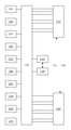
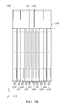
- FIGS. 1A and 1B are top views of a blade server in one embodiment of the invention.
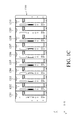
- FIG. 1C is a front view of the blade server in FIG. 1A ;
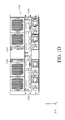
- FIG. 1D is a back view of the blade server in FIG. 1A ;
- FIG. 2 is a block diagram of the blade server in one embodiment of the invention.
- FIG. 3 is a functional block diagram of the blade server in another embodiment of the invention.
- FIG. 4 is a functional block diagram of the blade server module board in one embodiment of the invention.
- FIG. 5 is an architecture of the blade server module board in one embodiment of the invention.
- FIG. 6 is an architecture of the blade server module board in another embodiment of the invention.
- FIGS. 1A and 1B are top views of a blade server in one embodiment of the invention
- FIG. 1C is a front view of the blade server in FIG. 1A
- FIG. 1D is a back view of the blade server in FIG. 1A
- a blade server 1000 in one embodiment of the invention has a casing 1100 , a plurality of blade server module boards 1201 ⁇ 1210 , a first chassis management controller (CMC) 1310 and a second CMC 1320 .
- CMC chassis management controller
- FIG. 1A through FIG. 1D please refer to the auxiliary coordinates system X-Y-Z.
- the direction of negative X-axis is defined as the left side of the blade server
- the direction of positive X-axis is defined as the right side of the blade server
- the direction of negative Y-axis is defined as the first side of the blade server
- the direction of positive Y-axis is defined as the second side of the blade server
- the direction of negative Z-axis is defined as the bottom of the blade server
- the direction of positive Z-axis is defined as the upper side of the blade server.
- main board slots 1101 ⁇ 1110 there are a plurality of main board slots 1101 ⁇ 1110 at the first side of the casing 1100 and at least a first CMC slot 1111 and a second CMC slot 1113 at the second side of the casing 1100 .
- the plurality of main board slots 1101 ⁇ 1110 are all electrically connected to both of the first CMC slot 1111 and the second CMC slot 1113 .
- the first CMC slot 1111 and the second CMC slot 1113 are electrically connected to each other.
- the electrical connection between each of the main board slots 1101 ⁇ 1110 and both of the first CMC slot 1111 and the second CMC slot 1113 is implemented by the mid-plane 1115 .
- the mid plane 1115 is inserted into the casing 1100 from upper side to bottom, so the mid-plane 1115 is respectively electrically connected to the main board slots 1101 ⁇ 1110 , the first CMC slot 1111 and the second CMC slot 1113 .
- the main board slot 1101 ⁇ 1110 is electrically connected to the first CMC slot 1111 and the second CMC slot 1113 via the mid-plane 1115 .
- the plurality of blade server module boards 1201 ⁇ 1210 are plugged into the plurality of main board slots 1101 ⁇ 1110 .
- the first CMC 1310 is plugged into the first CMC slot 1111 so as to be electrically connected to the plurality of blade server module boards 1201 ⁇ 1210 .
- the second CMC 1320 is plugged into the second CMC slot 1113 so as to be electrically connected to the first CMC 1310 and the plurality of blade server module board 1201 ⁇ 1210 .
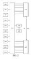
- FIG. 2 is a block diagram of the blade server in one embodiment of the invention.
- the first CMC 1310 and the second CMC 1320 of the blade server 1000 are both electrically connected to the blade server module boards 1201 ⁇ 1210 via the mid-plane 1115 .
- the second CMC 1320 is the redundant of the first CMC 1310 .
- the second CMC 1320 detects the operation status of the first CMC 1310 and generates a corresponding detection signal Vdet based on whether the first CMC 1310 functions normally.
- the second CMC 1320 detects the operation status of the first CMC 1310 is explained in the following.
- the second CMC 1320 periodically or randomly sends a request signal req to the first CMC 1310 .
- the request signal req for example, request for certain data. If the second CMC 1320 does not receive the response packet resp from the first CMC 1310 in a period after the request signal is sent, the second CMC 1320 determines the first CMC 1310 malfunctioning. If the second CMC 1320 receives the response packet resp from the first CMC 1310 in time, the second CMC 1320 determines the first CMC 1320 functioning normally.
- the second CMC 1320 further verifies whether the response packet resp from the first CMC 1310 is correct or not so as to determine whether the first CMC 1310 functions normally.
- the second CMC 1320 detects whether the first CMC 1310 functions normally, and the invention does not limit thereto.
- the detection signal Vdet generated by the second CMC 1320 is, for example, at high voltage.
- the detection signal Vdet is, for example, at low voltage.
- the blade server module boards 1201 ⁇ 1210 is controlled by the first CMC 1310 .
- the blade server module boards 1201 ⁇ 1210 is controlled by the second CMC 1320 .
- the blade server module boards 1201 ⁇ 1205 are, for example, primarily controlled by the first CMC 1310
- the blade server module boards 1206 ⁇ 1210 are, for example, primarily controlled by the second CMC 1320 .
- the first CMC 1310 also detects whether the second CMC 1320 functions normally. Explicitly, in the aforementioned embodiment, the second CMC 1320 sends a request signal req to the first CMC 1310 , and waits for the response packet resp from the first CMC 1310 .
- the response packet resp sent from the first CMC 1310 is, for example, a request signal from the first CMC 1310 to the second CMC 1320
- the request signal req sent from the second CMC 1320 is identified by the first CMC 1310 as the response packet from the second CMC 1320 to the first CMC 1310 .
- the second CMC 1320 detects the first CMC 1310 malfunctioning
- the second CMC 1320 controls the blade server module boards 1201 ⁇ 1205 to be controlled by the second CMC 1320
- the first CMC 1310 controls the blade server module boards 1206 ⁇ 1210 to be controlled by the first CMC 1310 .
- FIG. 1A ?? FIG. 1D There are furtherly a first switch slot and a second switch slot electrically connected to the main board slots 1101 ⁇ 1110 at the second side of the casing 1100 .
- the second switch 1420 is electrically connected to the blade server module boards 1201 ⁇ 1210 plugged in the main board slots 1101 ⁇ 1110 via the second switch slot and the mid-plane 1115 .
- the first switch 1410 and the second switch 1420 are both electrically connected to the blade server module boards 1201 ⁇ 1210 via the mid-plane 111 .
- the first switch 1410 and the second switch 1420 are, for example, configured to serve each of the blade server module boards 1201 ⁇ 1210 with the network communication ability or other communication ability.
- one of the first switch 1410 and the second switch 1420 fails, the blade server module boards 1201 ⁇ 1210 use the other one thereof to send signal so that it is prevented that the blade server module boards lose the communication ability while one switch fails.
- FIG. 3 is a functional block diagram of the blade server in another embodiment of the invention.
- the blade server 1000 ′ compared with the embodiment in FIG. 2 , further has a third switch 1430 and a fourth switch 1440 .
- the third switch 1430 is electrically connected to the first CMC 1310 and the blade server module boards 1201 ⁇ 1210 .
- the third switch 1430 is configured to perform the signal transmission between the first CMC 1310 and one of the blade server module boards 1201 ⁇ 1210 .
- the fourth switch 1440 is electrically connected to the second CMC 1320 and the blade server module boards 1201 ⁇ 1210 , and configured to perform the signal transmission between the second CMC 1320 and one of the blade server module boards 1201 ⁇ 1210 .
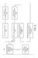
- FIG. 4 is a functional block diagram of the blade server module board in one embodiment of the invention.
- the blade server module board 1201 has a baseboard management controller BMC, a first inter-integrated circuit IIC 1 and a second IIC 2 .
- the first inter-integrated circuit IIC 1 is respectively electrically connected to the baseboard management controller BMC and the first CMC 1310
- the second inter-integrated circuit IIC 2 is respectively electrically connected to the baseboard management controller BMC and the second CMC 1320 .
- the baseboard management controller BMC receives the detection signal Vdet via the second inter-integrated circuit IIC 2 , and selects one of the first inter-integrated circuit IIC 1 and the second inter-integrated circuit IIC 2 to receive and/or send signal based on the detection signal Vdet.
- the second CMC 1320 has additional one pin electrically connected to the baseboard management controller BMC via the mid-plane 1115 . The baseboard management controller BMC selects one of the first inter-integrated circuit IIC 1 and the second inter-integrated circuit IIC 2 to receive and/or send signal based on the detection signal Vdet from this pin.
- the blade server module board 1201 is further electrically connected to the complex programmable logic device CPLD of the baseboard management controller BMC.
- the complex programmable logic device CPLD has a first serial general purpose input/output port SGPIO 1 and a second serial general purpose input/output port SGPIO 2 .
- the complex programmable logic device CPLD is electrically connected to the first CMC 1310 via the first serial general purpose input/output port SGPIO 1 and to the second CMC 1320 via the second serial general purpose input/output port SGPIO 2 .
- the baseboard management controller BMC generates a corresponding control signal Vc based on the detection signal Vdet to control the complex programmable logic device CPLD either to communicate with the first CMC 1310 via the first serial general purpose input/output port SGPIO 1 or to communicate with the second CMC 1320 via the second serial general purpose input/output port SGPIO 2 .
- the invention further provides an architecture of the blade server module board.
- FIG. 5 is an architecture of the blade server module board in one embodiment of the invention.
- the blade server module board 1201 has a first baseboard 1201 A, a second baseboard 1201 B, and a bridging board 1201 C.
- the first baseboard 1201 A has a first bridging bus BUS 1 .
- the second baseboard 1201 B is configured to be plugged in the corresponding main board slot so as to be electrically connected to the first CMC 1310 and the second CMC 1320 .
- the second baseboard 1201 B has a second bridging bus BUS 2 .
- the bridging board 1201 C has a first socket SKT 1 and a second socket SKT 2 , the first socket SKT 1 is pluggably connected to the first bridging bus BUS 1 and the second socket SKT 2 is pluggably connected to the second bridging bus BUS 2 .
- the baseboard management controller BMC, the first inter-integrated circuit IIC 1 , and the second inter-integrated circuit IIC 2 are all disposed on the first baseboard 1201 A.
- the first inter-integrated circuit IIC 1 and the second inter-integrated circuit IIC 2 are respective electrically connected to the first CMC 1310 and the second CMC 1320 via the bridging board 1201 C and the second baseboard 1201 B. Practically, there are a variety models of the blade server module board.
- the thickness of the baseboard and the pin count of one model of the blade server module board are different from those of another one model.
- the blade server module board no matter what the specification of its first baseboard is, the second baseboard with unified specification is used for being pluggably connected to the main board slot.
- this embodiment is different from the embodiment in FIG. 5 at that there is a gap G between the first baseboard 1201 A and the second baseboard 1201 B.
- the gap G is a room for a specific electronic element such as a hard disk backplane in one embodiment.
- the second CMC detects whether the first CMC functions normally so as to make the blade server module boards controlled by either the first CMC or the second CMC based on the detection result. Hence, when the first CMC malfunctions or needs to be repaired, the blade server module boards in the same blade server can be temporarily controlled by the second CMC functioning normally.
Landscapes
- Engineering & Computer Science (AREA)
- Theoretical Computer Science (AREA)
- General Engineering & Computer Science (AREA)
- Physics & Mathematics (AREA)
- Computer Hardware Design (AREA)
- General Physics & Mathematics (AREA)
- Power Engineering (AREA)
- Human Computer Interaction (AREA)
- Quality & Reliability (AREA)
- Mathematical Physics (AREA)
- Software Systems (AREA)
- Microelectronics & Electronic Packaging (AREA)
- Multi Processors (AREA)
- Supply And Installment Of Electrical Components (AREA)
Abstract
A blade server has a casing, a plurality of blade server module boards, a first chassis management controller (CMC) and a second CMC. There are a plurality of main board slots at a first side of the casing and at least a first CMC slot and a second CMC slot at a second side of the casing opposite to the first side. The plurality of main board slots are all electrically connected to both of the first CMC slot and the second CMC slot, wherein the first CMC slot and the second CMC slot are electrically connected to each other. The plurality of blade server module boards are plugged into the plurality of main board slots. The first CMC and the second CMC are redundant to each other. When one of the two CMCs malfunctions, the blade server module boards are controlled by the other one CMC functioning normally.
Description
- This non-provisional application claims priority under 35 U.S.C. § 119(a) on Patent Application No(s). 201711231769.4 filed in China, on Nov. 30, 2017, the entire contents of which are hereby incorporated by reference.
- This invention relates to a blade server, and particularly to a 4 U blade server.
- A conventional server generally has standard elements such as chassis, power, main board, storage medium, and etc. However, one chassis conventionally has only one chassis management controller. Although some servers have more than one chassis management controller in one chassis to control more than one server board, those chassis management controller cannot mutually support. One of those chassis management controllers fails, the server board controlled by that chassis management controller cannot be used by the user.
- In one embodiment of the invention, a blade server has a casing, a plurality of blade server module board, a first chassis management controller (CMC), and a second CMC. The casing has a plurality of main board slots at a first side of the casing and at least a first CMC slot and a second CMC slot at a second side of the casing opposite to the first side, wherein the plurality of main board slots are all electrically connected to the first CMC slot and the second CMC slot, and the first CMC slot is electrically connected to the second CMC slot. The plurality of blade server module boards are plugged in the plurality of main board slots. The first CMC is plugged in the first CMC slot to be electrically connected to the plurality of blade server module boards. The second CMC is plugged in the second CMC slot to be electrically connected to the first CMC and the plurality of blade server module boards, wherein the second CMC detects the first CMC to generate a detection signal based on whether the first CMC functions normally. When the first CMC functions normally, the plurality of blade server module boards is controlled by the first CMC based on the detection signal, and controlled by the second CMC based on the detection signal otherwise.
- The present disclosure will become more fully understood from the detailed description given hereinbelow and the accompanying drawings which are given by way of illustration only and thus are not limitative of the present disclosure and wherein:
-
FIGS. 1A and 1B are top views of a blade server in one embodiment of the invention; -
FIG. 1C is a front view of the blade server inFIG. 1A ; -
FIG. 1D is a back view of the blade server inFIG. 1A ; -
FIG. 2 is a block diagram of the blade server in one embodiment of the invention; -
FIG. 3 is a functional block diagram of the blade server in another embodiment of the invention; -
FIG. 4 is a functional block diagram of the blade server module board in one embodiment of the invention; -
FIG. 5 is an architecture of the blade server module board in one embodiment of the invention; and -
FIG. 6 is an architecture of the blade server module board in another embodiment of the invention. - In the following detailed description, for purposes of explanation, numerous specific details are set forth in order to provide a thorough understanding of the disclosed embodiments. It will be apparent, however, that one or more embodiments may be practiced without these specific details. In other instances, well-known structures and devices are schematically shown in order to simplify the drawings.
- Please refer to
FIG. 1A throughFIG. 1D , whereinFIGS. 1A and 1B are top views of a blade server in one embodiment of the invention,FIG. 1C is a front view of the blade server inFIG. 1A , andFIG. 1D is a back view of the blade server inFIG. 1A . As shown inFIG. 1A ˜FIG. 1D , ablade server 1000 in one embodiment of the invention has acasing 1100, a plurality of bladeserver module boards 1201˜1210, a first chassis management controller (CMC) 1310 and asecond CMC 1320. InFIG. 1A throughFIG. 1D , please refer to the auxiliary coordinates system X-Y-Z. In the following embodiment, the direction of negative X-axis is defined as the left side of the blade server, the direction of positive X-axis is defined as the right side of the blade server, the direction of negative Y-axis is defined as the first side of the blade server, the direction of positive Y-axis is defined as the second side of the blade server, the direction of negative Z-axis is defined as the bottom of the blade server, and the direction of positive Z-axis is defined as the upper side of the blade server. - There are a plurality of
main board slots 1101˜1110 at the first side of thecasing 1100 and at least afirst CMC slot 1111 and asecond CMC slot 1113 at the second side of thecasing 1100. The plurality ofmain board slots 1101˜1110 are all electrically connected to both of thefirst CMC slot 1111 and thesecond CMC slot 1113. Thefirst CMC slot 1111 and thesecond CMC slot 1113 are electrically connected to each other. - In one embodiment, the electrical connection between each of the
main board slots 1101˜1110 and both of thefirst CMC slot 1111 and thesecond CMC slot 1113 is implemented by the mid-plane 1115. When theblade server 1000 is assembled, themid plane 1115 is inserted into thecasing 1100 from upper side to bottom, so the mid-plane 1115 is respectively electrically connected to themain board slots 1101˜1110, thefirst CMC slot 1111 and thesecond CMC slot 1113. Hence, themain board slot 1101˜1110 is electrically connected to thefirst CMC slot 1111 and thesecond CMC slot 1113 via the mid-plane 1115. - The plurality of blade
server module boards 1201˜1210 are plugged into the plurality ofmain board slots 1101˜1110. - The
first CMC 1310 is plugged into thefirst CMC slot 1111 so as to be electrically connected to the plurality of bladeserver module boards 1201˜1210. Thesecond CMC 1320 is plugged into thesecond CMC slot 1113 so as to be electrically connected to thefirst CMC 1310 and the plurality of bladeserver module board 1201˜1210. - Please refer to
FIG. 2 , which is a block diagram of the blade server in one embodiment of the invention. As shown inFIG. 2 , thefirst CMC 1310 and thesecond CMC 1320 of theblade server 1000 are both electrically connected to the bladeserver module boards 1201˜1210 via the mid-plane 1115. In the embodiment inFIG. 2 , thesecond CMC 1320 is the redundant of thefirst CMC 1310. Explicitly, thesecond CMC 1320 detects the operation status of thefirst CMC 1310 and generates a corresponding detection signal Vdet based on whether thefirst CMC 1310 functions normally. - How the
second CMC 1320 detects the operation status of thefirst CMC 1310 is explained in the following. In one embodiment, thesecond CMC 1320 periodically or randomly sends a request signal req to thefirst CMC 1310. The request signal req, for example, request for certain data. If thesecond CMC 1320 does not receive the response packet resp from thefirst CMC 1310 in a period after the request signal is sent, thesecond CMC 1320 determines thefirst CMC 1310 malfunctioning. If thesecond CMC 1320 receives the response packet resp from thefirst CMC 1310 in time, thesecond CMC 1320 determines thefirst CMC 1320 functioning normally. In another embodiment, thesecond CMC 1320 further verifies whether the response packet resp from thefirst CMC 1310 is correct or not so as to determine whether thefirst CMC 1310 functions normally. In addition, one having ordinary skill in the art is capable designing how thesecond CMC 1320 detects whether thefirst CMC 1310 functions normally, and the invention does not limit thereto. - In one embodiment, when the
first CMC 1310 functions normally, the detection signal Vdet generated by thesecond CMC 1320 is, for example, at high voltage. When thefirst CMC 1310 malfunctions, the detection signal Vdet is, for example, at low voltage. When the detection signal Vdet is at high voltage, the bladeserver module boards 1201˜1210 is controlled by thefirst CMC 1310. When the detection signal Vdet is at low voltage, the bladeserver module boards 1201˜1210 is controlled by thesecond CMC 1320. - In another embodiment, the blade
server module boards 1201˜1205 are, for example, primarily controlled by thefirst CMC 1310, and the bladeserver module boards 1206˜1210 are, for example, primarily controlled by thesecond CMC 1320. Thefirst CMC 1310 also detects whether thesecond CMC 1320 functions normally. Explicitly, in the aforementioned embodiment, thesecond CMC 1320 sends a request signal req to thefirst CMC 1310, and waits for the response packet resp from thefirst CMC 1310. In this embodiment, the response packet resp sent from thefirst CMC 1310 is, for example, a request signal from thefirst CMC 1310 to thesecond CMC 1320, and the request signal req sent from thesecond CMC 1320 is identified by thefirst CMC 1310 as the response packet from thesecond CMC 1320 to thefirst CMC 1310. When thesecond CMC 1320 detects thefirst CMC 1310 malfunctioning, thesecond CMC 1320 controls the bladeserver module boards 1201˜1205 to be controlled by thesecond CMC 1320. On the contrary, when thefirst CMC 1310 detects thesecond CMC 1320 malfunctioning, thefirst CMC 1310 controls the bladeserver module boards 1206˜1210 to be controlled by thefirst CMC 1310. - In one embodiment, please go back to
FIG. 1A ˜FIG. 1D . There are furtherly a first switch slot and a second switch slot electrically connected to themain board slots 1101˜1110 at the second side of thecasing 1100. There is afirst switch 1410 plugged in the first switch slot, and thefirst switch 1410 is electrically connected to the bladeserver module boards 1201˜1210 plugged in themain board slots 1101˜1110 via the first switch slot and the mid-plane 1115. There is asecond switch 1420 plugged in the second switch slot, and thesecond switch 1420 is electrically connected to the bladeserver module boards 1201˜1210 plugged in themain board slots 1101˜1110 via the second switch slot and the mid-plane 1115. Please refer toFIG. 2 . As shown inFIG. 2 , thefirst switch 1410 and thesecond switch 1420 are both electrically connected to the bladeserver module boards 1201˜1210 via the mid-plane 111. Explicitly, thefirst switch 1410 and thesecond switch 1420 are, for example, configured to serve each of the bladeserver module boards 1201˜1210 with the network communication ability or other communication ability. Further, one of thefirst switch 1410 and thesecond switch 1420 fails, the bladeserver module boards 1201˜1210 use the other one thereof to send signal so that it is prevented that the blade server module boards lose the communication ability while one switch fails. - In another embodiment, please refer to
FIG. 3 , which is a functional block diagram of the blade server in another embodiment of the invention. As shown inFIG. 3 , theblade server 1000′, compared with the embodiment inFIG. 2 , further has athird switch 1430 and afourth switch 1440. Thethird switch 1430 is electrically connected to thefirst CMC 1310 and the bladeserver module boards 1201˜1210. Thethird switch 1430 is configured to perform the signal transmission between thefirst CMC 1310 and one of the bladeserver module boards 1201˜1210. Thefourth switch 1440 is electrically connected to thesecond CMC 1320 and the bladeserver module boards 1201˜1210, and configured to perform the signal transmission between thesecond CMC 1320 and one of the bladeserver module boards 1201˜1210. - Please then refer to
FIG. 4 , which is a functional block diagram of the blade server module board in one embodiment of the invention. As shown inFIG. 4 , taking the bladeserver module board 1201 for example, the bladeserver module board 1201 has a baseboard management controller BMC, a first inter-integrated circuit IIC1 and a second IIC2. The first inter-integrated circuit IIC1 is respectively electrically connected to the baseboard management controller BMC and thefirst CMC 1310, and the second inter-integrated circuit IIC2 is respectively electrically connected to the baseboard management controller BMC and thesecond CMC 1320. In one embodiment, the baseboard management controller BMC receives the detection signal Vdet via the second inter-integrated circuit IIC2, and selects one of the first inter-integrated circuit IIC1 and the second inter-integrated circuit IIC2 to receive and/or send signal based on the detection signal Vdet. In another embodiment, thesecond CMC 1320 has additional one pin electrically connected to the baseboard management controller BMC via themid-plane 1115. The baseboard management controller BMC selects one of the first inter-integrated circuit IIC1 and the second inter-integrated circuit IIC2 to receive and/or send signal based on the detection signal Vdet from this pin. - In one embodiment, the blade
server module board 1201 is further electrically connected to the complex programmable logic device CPLD of the baseboard management controller BMC. The complex programmable logic device CPLD has a first serial general purpose input/output port SGPIO1 and a second serial general purpose input/output port SGPIO2. The complex programmable logic device CPLD is electrically connected to thefirst CMC 1310 via the first serial general purpose input/output port SGPIO1 and to thesecond CMC 1320 via the second serial general purpose input/output port SGPIO2. The baseboard management controller BMC generates a corresponding control signal Vc based on the detection signal Vdet to control the complex programmable logic device CPLD either to communicate with thefirst CMC 1310 via the first serial general purpose input/output port SGPIO1 or to communicate with thesecond CMC 1320 via the second serial general purpose input/output port SGPIO2. - In one embodiment, the invention further provides an architecture of the blade server module board. Please refer to
FIG. 5 , which is an architecture of the blade server module board in one embodiment of the invention. As shown inFIG. 5 , taking the bladeserver module board 1201 for example, the bladeserver module board 1201 has afirst baseboard 1201A, asecond baseboard 1201B, and a bridgingboard 1201C. Thefirst baseboard 1201A has a first bridging bus BUS1. Thesecond baseboard 1201B is configured to be plugged in the corresponding main board slot so as to be electrically connected to thefirst CMC 1310 and thesecond CMC 1320. Thesecond baseboard 1201B has a second bridging bus BUS2. The bridgingboard 1201C has a first socket SKT1 and a second socket SKT2, the first socket SKT1 is pluggably connected to the first bridging bus BUS1 and the second socket SKT2 is pluggably connected to the second bridging bus BUS2. The baseboard management controller BMC, the first inter-integrated circuit IIC1, and the second inter-integrated circuit IIC2 are all disposed on thefirst baseboard 1201A. The first inter-integrated circuit IIC1 and the second inter-integrated circuit IIC2 are respective electrically connected to thefirst CMC 1310 and thesecond CMC 1320 via the bridgingboard 1201C and thesecond baseboard 1201B. Practically, there are a variety models of the blade server module board. The thickness of the baseboard and the pin count of one model of the blade server module board are different from those of another one model. In this embodiment, the blade server module board, no matter what the specification of its first baseboard is, the second baseboard with unified specification is used for being pluggably connected to the main board slot. - In one embodiment, as shown in
FIG. 6 , this embodiment is different from the embodiment inFIG. 5 at that there is a gap G between thefirst baseboard 1201A and thesecond baseboard 1201B. The gap G is a room for a specific electronic element such as a hard disk backplane in one embodiment. - As above, in one embodiment of the invention, the second CMC detects whether the first CMC functions normally so as to make the blade server module boards controlled by either the first CMC or the second CMC based on the detection result. Hence, when the first CMC malfunctions or needs to be repaired, the blade server module boards in the same blade server can be temporarily controlled by the second CMC functioning normally.
Claims (9)
1. A blade server, comprising:
a casing having a plurality of main board slots at a first side of the casing and at least a first chassis management controller (CMC) slot and a second CMC slot at a second side of the casing opposite to the first side, wherein the plurality of main board slots are all electrically connected to the first CMC slot and the second CMC slot, and the first CMC slot is electrically connected to the second CMC slot;
a plurality of blade server module board plugged in the plurality of main board slots;
a first CMC plugged in the first CMC slot to be electrically connected to the plurality of blade server module boards;
a second CMC plugged in the second CMC slot to be electrically connected to the first CMC and the plurality of blade server module boards, wherein the second CMC detects the first CMC to generate a detection signal based on whether the first CMC functions normally;
a third switch electrically connected to the first CMC and the plurality of blade server module boards, and configured to perform a signal transmission between one among the plurality of blade server module boards and the first CMC; and
a fourth switch electrically connected to the second CMC and the plurality of blade server module boards, and configure to perform a signal transmission between one among the plurality of blade server module boards and the second CMC,
wherein when the first CMC functions normally, the plurality of blade server module boards is controlled by the first CMC based on the detection signal, and controlled by the second CMC based on the detection signal otherwise.
2. The blade server in claim 1 , further comprising:
a first switch slot at the second side of the casing and electrically connected to the plurality of main board slots;
a second switch slot at the second side of the casing and electrically connected to the plurality of main board slots;
a first switch plugged into the first switch slot to be electrically connected to the plurality of blade server module boards; and
a second switch plugged into the second switch slot to be electrically connected to the plurality of blade server module boards;
wherein when one of the first switch and the second switch fails, the plurality of blade server module boards send signal via the other one of the first switch and the second switch.
3. (canceled)
4. The blade server in claim 1 , wherein each of the blade server module boards comprises:
a baseboard management controller (BMC);
a first inter-integrated circuit (I2C) respectively electrically connected to the BMC and the first CMC; and
a second I2C respectively electrically connected to the BMC and the second CMC;
wherein the BMC selects one of the first I2C and the second I2C to receive or send signal based on the detection signal.
5. The blade server in claim 4 , wherein each of the blade server module boards further comprises:
a complex programmable logic device (CPLD) electrically connected to the baseboard management controller, wherein the CPLD comprises:
a first serial general purpose input/output (SGPIO) port electrically connected to the first CMC; and
a second SGPIO port electrically connected to the second CMC;
wherein the BMC controls the CPLD to receive or send signal via either the first SGPIO port or the second SGPIO port based on the detection signal.
6. The blade server in claim 4 , wherein each of the blade server module boards further comprises:
a first baseboard has a first bridging bus;
a second baseboard configured to pluggably connected to the corresponding main board slot to be electrically connected to the first CMC and the second CMC, wherein the second baseboard has a second bridging bus; and
a bridging board having a first socket pluggably connected to the first bridging bus and a second socket pluggably connected to the second bridging bus;
wherein the BMC, the first I2C and the second I2C are all on the first baseboard, and the first I2C and the second I2C are electrically connected to the first CMC and the second CMC via the bridging board and the second baseboard.
7. The blade server in claim 6 , wherein a gap between the first baseboard and the second baseboard forms a room for an electronic element.
8. The blade server in claim 7 , wherein the electronic element is a hard disk backplane.
9. The blade server in claim 1 , further comprising a mid-plane in the casing and respectively electrically connected to the plurality of main board slots, the first CMC slot and the second CMC slot, wherein the plurality of main board slots are electrically connected to the first CMC slot and the second CMC slot via the mid-plane.
Applications Claiming Priority (3)
| Application Number | Priority Date | Filing Date | Title |
|---|---|---|---|
| CN201711231769.4 | 2017-11-30 | ||
| CN201711231769.4A CN108628412A (en) | 2017-11-30 | 2017-11-30 | Cutter point server |
| CN201711231769 | 2017-11-30 |
Publications (2)
| Publication Number | Publication Date |
|---|---|
| US10303224B1 US10303224B1 (en) | 2019-05-28 |
| US20190163243A1 true US20190163243A1 (en) | 2019-05-30 |
Family
ID=63705912
Family Applications (1)
| Application Number | Title | Priority Date | Filing Date |
|---|---|---|---|
| US15/870,505 Active US10303224B1 (en) | 2017-11-30 | 2018-01-12 | Blade server |
Country Status (2)
| Country | Link |
|---|---|
| US (1) | US10303224B1 (en) |
| CN (1) | CN108628412A (en) |
Families Citing this family (1)
| Publication number | Priority date | Publication date | Assignee | Title |
|---|---|---|---|---|
| CN110347555B (en) * | 2019-07-09 | 2021-10-01 | 英业达科技有限公司 | Hard disk operation state determination method |
Family Cites Families (17)
| Publication number | Priority date | Publication date | Assignee | Title |
|---|---|---|---|---|
| CN1257464C (en) * | 2002-12-18 | 2006-05-24 | 广达电脑股份有限公司 | Blade Server Management System with Hardware Standby Structure |
| US7191347B2 (en) * | 2002-12-31 | 2007-03-13 | International Business Machines Corporation | Non-disruptive power management indication method, system and apparatus for server |
| US7193847B2 (en) * | 2005-03-31 | 2007-03-20 | Quanta Computer Inc. | Blade server system |
| US7676666B2 (en) * | 2006-02-02 | 2010-03-09 | Dell Products L.P. | Virtual BIOS firmware hub |
| US7850260B2 (en) * | 2007-06-22 | 2010-12-14 | Oracle America, Inc. | Injection/ejection mechanism |
| CN101894055A (en) * | 2010-07-21 | 2010-11-24 | 浪潮电子信息产业股份有限公司 | A Realization Method of Blade Motherboard Interface with Redundant Function |
| CN102346514B (en) * | 2010-07-30 | 2013-06-12 | 英业达股份有限公司 | server blade module |
| CN102098196B (en) * | 2010-12-10 | 2016-04-13 | 曙光信息产业(北京)有限公司 | The data transmission method of blade server |
| CN102253872A (en) * | 2011-07-07 | 2011-11-23 | 浪潮电子信息产业股份有限公司 | Method for implementing redundant management module in compact peripheral component interconnect (CPCI) blade server |
| CN103135682B (en) * | 2011-11-30 | 2016-03-02 | 英业达科技有限公司 | Blade server |
| CN203133686U (en) * | 2013-03-21 | 2013-08-14 | 浪潮电子信息产业股份有限公司 | Blade server capable of configuring PCIE (peripheral component interface express) card or hard disc flexibly |
| CN103428033B (en) * | 2013-08-20 | 2018-05-18 | 浪潮电子信息产业股份有限公司 | A kind of active detection method for blade server management network |
| CN103473152B (en) * | 2013-09-25 | 2017-03-01 | 郑州云海信息技术有限公司 | A kind of active and standby management module backup of blade server and update method |
| CN103885860A (en) * | 2014-03-21 | 2014-06-25 | 浪潮集团有限公司 | Method for achieving BMC double-management hot redundancy by applying IPMI command |
| CN104125312A (en) * | 2014-07-10 | 2014-10-29 | 浪潮集团有限公司 | Method for achieving effect that redundancy management modules share one IP (Internet Protocol) address in blade server |
| CN105425918A (en) * | 2015-12-16 | 2016-03-23 | 英业达科技有限公司 | Miniature server system |
| US10067548B2 (en) * | 2016-05-19 | 2018-09-04 | Dell Products L.P. | Efficient power-on sequence for a modular information handling system |
-
2017
- 2017-11-30 CN CN201711231769.4A patent/CN108628412A/en active Pending
-
2018
- 2018-01-12 US US15/870,505 patent/US10303224B1/en active Active
Also Published As
| Publication number | Publication date |
|---|---|
| CN108628412A (en) | 2018-10-09 |
| US10303224B1 (en) | 2019-05-28 |
Similar Documents
| Publication | Publication Date | Title |
|---|---|---|
| US9619243B2 (en) | Synchronous BMC configuration and operation within cluster of BMC | |
| JP2024513663A (en) | High-density peripheral card chassis | |
| US20050033890A1 (en) | Hot-pluggable peripheral input device coupling system | |
| US20120047302A1 (en) | Storage system | |
| CN105718785B (en) | Computer implementation and system for authentication-free configuration | |
| GB2492620A (en) | Midplane for blade server management | |
| CN104281511A (en) | Intelligent platform management interface system, substrate management controller and implementation method | |
| US8694987B2 (en) | Server rack system | |
| TWI831190B (en) | Datacenter-ready secure control module and control method | |
| CN105549696A (en) | Rack-mounted server system with case management function | |
| US20170336856A1 (en) | Systems and methods for autonomously adapting powering budgeting in a multi-information handling system passive chassis environment | |
| CN106940676B (en) | Monitoring system of cabinet | |
| CN103793003A (en) | Exchange plate and blade server | |
| US10303224B1 (en) | Blade server | |
| CN106249838B (en) | Method for server power supply, backplane and server | |
| CN101453337A (en) | Micro telecommunication and computer general hardware platform architecture system and electric power control method | |
| TW201729097A (en) | Rack | |
| CN107179818B (en) | Control circuit and control method of double mainboards | |
| CN205827319U (en) | The redundant apparatus of a kind of computer bottom plate and computer | |
| CN115551272A (en) | Server management method and device and cabinet | |
| US10474602B2 (en) | System and method for distributed console server architecture | |
| CN102193850A (en) | A time updating system for multi-main board server | |
| CN114153777A (en) | Server and hot plug method and system thereof | |
| TW201926067A (en) | Blade server | |
| CN114356060A (en) | Master-slave interchange type power supply device, power supply method and host |
Legal Events
| Date | Code | Title | Description |
|---|---|---|---|
| FEPP | Fee payment procedure |
Free format text: ENTITY STATUS SET TO UNDISCOUNTED (ORIGINAL EVENT CODE: BIG.); ENTITY STATUS OF PATENT OWNER: LARGE ENTITY |
|
| STCF | Information on status: patent grant |
Free format text: PATENTED CASE |
|
| MAFP | Maintenance fee payment |
Free format text: PAYMENT OF MAINTENANCE FEE, 4TH YEAR, LARGE ENTITY (ORIGINAL EVENT CODE: M1551); ENTITY STATUS OF PATENT OWNER: LARGE ENTITY Year of fee payment: 4 |