US20190162615A1 - Pressure sensor and pressure sensor module - Google Patents
Pressure sensor and pressure sensor module Download PDFInfo
- Publication number
- US20190162615A1 US20190162615A1 US16/260,659 US201916260659A US2019162615A1 US 20190162615 A1 US20190162615 A1 US 20190162615A1 US 201916260659 A US201916260659 A US 201916260659A US 2019162615 A1 US2019162615 A1 US 2019162615A1
- Authority
- US
- United States
- Prior art keywords
- pressure
- detection unit
- region
- medium
- pressure sensor
- Prior art date
- Legal status (The legal status is an assumption and is not a legal conclusion. Google has not performed a legal analysis and makes no representation as to the accuracy of the status listed.)
- Abandoned
Links
- 238000001514 detection method Methods 0.000 claims abstract description 119
- 239000000758 substrate Substances 0.000 claims description 39
- 238000005192 partition Methods 0.000 claims description 23
- 239000007788 liquid Substances 0.000 claims description 8
- 230000035882 stress Effects 0.000 description 11
- 238000004519 manufacturing process Methods 0.000 description 5
- 239000000463 material Substances 0.000 description 4
- 239000012530 fluid Substances 0.000 description 3
- 239000003822 epoxy resin Substances 0.000 description 2
- 238000012986 modification Methods 0.000 description 2
- 230000004048 modification Effects 0.000 description 2
- 239000003921 oil Substances 0.000 description 2
- 229920000647 polyepoxide Polymers 0.000 description 2
- 229920002050 silicone resin Polymers 0.000 description 2
- 230000003068 static effect Effects 0.000 description 2
- XLYOFNOQVPJJNP-UHFFFAOYSA-N water Substances O XLYOFNOQVPJJNP-UHFFFAOYSA-N 0.000 description 2
- 238000006073 displacement reaction Methods 0.000 description 1
- 230000000694 effects Effects 0.000 description 1
- 230000006355 external stress Effects 0.000 description 1
- 238000009499 grossing Methods 0.000 description 1
- 238000000034 method Methods 0.000 description 1
- 238000000926 separation method Methods 0.000 description 1
- 229910052710 silicon Inorganic materials 0.000 description 1
- 239000010703 silicon Substances 0.000 description 1
Images


Classifications
-
- G—PHYSICS
- G01—MEASURING; TESTING
- G01L—MEASURING FORCE, STRESS, TORQUE, WORK, MECHANICAL POWER, MECHANICAL EFFICIENCY, OR FLUID PRESSURE
- G01L13/00—Devices or apparatus for measuring differences of two or more fluid pressure values
- G01L13/02—Devices or apparatus for measuring differences of two or more fluid pressure values using elastically-deformable members or pistons as sensing elements
- G01L13/025—Devices or apparatus for measuring differences of two or more fluid pressure values using elastically-deformable members or pistons as sensing elements using diaphragms
-
- G—PHYSICS
- G01—MEASURING; TESTING
- G01L—MEASURING FORCE, STRESS, TORQUE, WORK, MECHANICAL POWER, MECHANICAL EFFICIENCY, OR FLUID PRESSURE
- G01L13/00—Devices or apparatus for measuring differences of two or more fluid pressure values
-
- G—PHYSICS
- G01—MEASURING; TESTING
- G01L—MEASURING FORCE, STRESS, TORQUE, WORK, MECHANICAL POWER, MECHANICAL EFFICIENCY, OR FLUID PRESSURE
- G01L19/00—Details of, or accessories for, apparatus for measuring steady or quasi-steady pressure of a fluent medium insofar as such details or accessories are not special to particular types of pressure gauges
- G01L19/0007—Fluidic connecting means
- G01L19/0038—Fluidic connecting means being part of the housing
-
- G—PHYSICS
- G01—MEASURING; TESTING
- G01L—MEASURING FORCE, STRESS, TORQUE, WORK, MECHANICAL POWER, MECHANICAL EFFICIENCY, OR FLUID PRESSURE
- G01L19/00—Details of, or accessories for, apparatus for measuring steady or quasi-steady pressure of a fluent medium insofar as such details or accessories are not special to particular types of pressure gauges
- G01L19/06—Means for preventing overload or deleterious influence of the measured medium on the measuring device or vice versa
- G01L19/0627—Protection against aggressive medium in general
- G01L19/0654—Protection against aggressive medium in general against moisture or humidity
-
- G—PHYSICS
- G01—MEASURING; TESTING
- G01L—MEASURING FORCE, STRESS, TORQUE, WORK, MECHANICAL POWER, MECHANICAL EFFICIENCY, OR FLUID PRESSURE
- G01L19/00—Details of, or accessories for, apparatus for measuring steady or quasi-steady pressure of a fluent medium insofar as such details or accessories are not special to particular types of pressure gauges
- G01L19/14—Housings
-
- G—PHYSICS
- G01—MEASURING; TESTING
- G01L—MEASURING FORCE, STRESS, TORQUE, WORK, MECHANICAL POWER, MECHANICAL EFFICIENCY, OR FLUID PRESSURE
- G01L19/00—Details of, or accessories for, apparatus for measuring steady or quasi-steady pressure of a fluent medium insofar as such details or accessories are not special to particular types of pressure gauges
- G01L19/14—Housings
- G01L19/142—Multiple part housings
Definitions
- the present invention relates to pressure sensors and pressure sensor modules, and more particularly, to a pressure sensor and a pressure sensor module that have two detection units that detect pressure of respective media that differ from each other.
- Japanese Unexamined Patent Application Publication No. 2007-003383 discloses a configuration of a pressure sensor that determines an absolute pressure of a pressure medium with respect to a vacuum pressure by using the difference between a pressure detected by a first sensing unit and a pressure detected by a second sensing unit and the difference between the pressure detected by the first sensing unit and a pressure detected by a third sensing unit.
- Each of the first sensing unit and the second sensing unit in this pressure sensor has a protecting member to protect a pressure-receiving surface from the pressure medium.
- Japanese Unexamined Patent Application Publication No. 2008-304245 discloses a pressure sensor which includes a casing in which a first pressure cavity and a second pressure cavity into which respective pressure media are introduced are desposed, a first sensor chip and a second sensor chip that have the same characteristics, protecting members for protecting the respective sensor chips, and vibration-constraint members for constraining the respective protecting members from moving.
- This pressure sensor reduces an effect of external stress, such as vibration, to which the plurality of sensor chips, which have the protecting members on the pressure-receiving surfaces, are subjected.
- Japanese Unexamined Patent Application Publication No. 2012-189349 discloses a flow rate sensor which includes a casing exposed to a fluid, a first container space and a second container space that are disposed in the casing, a dynamic pressure introduction port disposed at the leading edge of the casing, a static pressure introduction port disposed on a side of the casing, a first pressure-receiving sensor contained in the first container space, and a second pressure-receiving sensor contained in the second container space.
- the dynamic pressure introduction port of this flow rate sensor is directed in a fluid flow direction
- the static pressure introduction port of this flow rate sensor is directed in the direction substantially perpendicular to the fluid flow direction.
- one of the plurality of pressure-receiving sensors does not affect a pressure change detected by the other of the plurality of pressure-receiving sensors.
- a diaphragm which undergoes displacement due to a pressure applied by a medium, is disposed in a detecting element that detects the pressure of the medium.
- a detecting element of a relative type detects the difference between a pressure of a medium on one side of a diaphragm and a pressure of a medium on the other side of the diaphragm.
- a single detecting element can detect a relative pressure of a medium with respect to a pressure of another medium.
- the present invention provides a pressure sensor and a pressure sensor module that have simple structures and are highly resistant to pressure.
- a pressure sensor includes a first detection unit that is disposed in a first region and that detects an absolute value of a pressure of a first medium, a second detection unit that is disposed in a second region separated from the first region and that detects an absolute value of a pressure of a second medium that differs from the first medium, and a calculation unit that performs a calculation to obtain a difference between a first pressure detected by the first detection unit and a second pressure detected by the second detection unit.
- Such a configuration in which the first detection unit and the second detection unit detect absolute values of respective pressures, can increase the pressure resistance of a diaphragm compared with a detection unit that detects a relative pressure.
- the first region in which the first detection unit is disposed and the second region in which the second detection unit is disposed are separated from each other, and thus the mixing of the first medium and the second medium can be suppressed even when the pressure resistance of the detection units is exceeded.
- the pressure sensor according to the present invention may further include a substrate and a package that covers at least a portion of the substrate and exteriors of the first detection unit, the second detection unit, and the calculation unit, and the package may include a partition that separates the first region from the second region. In this way, separation between the first region and the second region is ensured by using the partition of the package.
- the first detection unit, the second detection unit, and the calculation unit may be disposed on a first surface side, the first surface side being a surface of the substrate.
- the first detection unit, the second detection unit, and the calculation unit are disposed on the same surface side of the substrate (first surface side), and thus the structure and component mounting can be simplified.
- the package may have a through hole that connects the second region to a space outside the package.
- a medium outside the package is introduced as the second medium into the second region through the through hole, and the second detection unit can detect the pressure outside the package.
- the package may have an introduction hole that is disposed on the first surface side of the substrate and that enables a pressure of the first medium to be introduced to the first region.
- the first medium is introduced into the first region from the first surface side of the substrate through the introduction hole, and the first detection unit can detect the pressure of the first medium.
- each of the first detection unit and the second detection unit may include a diaphragm that deforms into a concave shape and that detects a pressure.
- a diaphragm that deforms into a concave shape and that detects a pressure.
- the first medium may be a liquid
- the second medium may be a gas
- a pressure sensor module includes a substrate, a package that covers at least a portion of the substrate, that forms a first region and a second region on a first surface side, the first surface side being a surface of the substrate, and that includes a partition that separates the first region from the second region, a first detection unit that is disposed in the first region and that detects an absolute value of a pressure of a first medium, a second detection unit that is disposed in the second region and that detects an absolute value of a pressure of a second medium that differs from the first medium, and a calculation unit that is disposed on the first surface side and that performs a calculation to obtain via a wiring pattern a difference between a first pressure detected by the first detection unit and a second pressure detected by the second detection unit.
- the package has a through hole that connects the second region to a space outside the package and an introduction hole that is disposed on the first surface side of the substrate and that enables a pressure of the first medium to be introduced to the first
- Such a configuration enables the package to contain the first detection unit, the second detection unit, and the calculation unit, and thus a pressure sensor can be configured by using a single component.
- this configuration in which the first detection unit and the second detection unit detect absolute values of respective pressures, can increase the pressure resistance of a diaphragm compared with a detection unit that detects a relative pressure.
- the first region and the second region are separated from each other in the package, and the first detection unit and the second detection unit are disposed in the first region and in the second region, respectively.
- the mixing of the first medium and the second medium can be suppressed even when the pressure resistance of the detection units is exceeded.
- FIG. 1 is a schematic cross-sectional view illustrating a pressure sensor according to an embodiment
- FIGS. 2A to 2D are schematic illustrations describing the pressure resistance of detection units
- FIGS. 3A and 3B are perspective views of a specific example of a pressure sensor module.
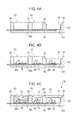
- FIGS. 4A to 4C are schematic cross-sectional views illustrating a method of manufacturing the pressure sensor module.
- FIG. 1 is a schematic cross-sectional view illustrating a pressure sensor according to the present embodiment.
- a pressure sensor 1 includes a first detection unit 10 that detects a pressure of a first medium, a second detection unit 20 that detects a pressure of a second medium, and a calculation unit 30 that performs a calculation.
- the first detection unit 10 is an absolute pressure sensor that detects an absolute value of the pressure of the first medium.
- the first detection unit 10 is disposed in a first region R 1 in the pressure sensor 1 .
- the second detection unit 20 is an absolute pressure sensor that detects an absolute value of the pressure of the second medium.
- the second detection unit 20 is disposed in a second region R 2 in the pressure sensor 1 .
- the first region R 1 and the second region R 2 are separated from each other.
- An absolute pressure sensor which constitutes each of the first detection unit 10 and the second detection unit 20 , includes a sensor chip having, for example, a diaphragm and a piezoresistive element.
- An absolute pressure sensor receives the pressure of a medium by using a diaphragm. Stress generated by deformation of the diaphragm is converted into an electric signal by using the piezoresistive element, and the pressure is detected.
- a diaphragm is disposed on a support member in a deformable fashion. When the diaphragm receives a pressure for detection, the diaphragm deforms toward the support member and forms a concave shape.
- the calculation unit 30 performs a calculation to obtain the difference between a first pressure P 1 detected by the first detection unit 10 and a second pressure P 2 detected by the second detection unit 20 .
- the pressure sensor 1 according to the present embodiment is able to obtain the difference between the first pressure P 1 , which is the absolute pressure of the first medium detected by the first detection unit 10 and the second pressure P 2 , which is the absolute pressure of the second medium detected by the second detection unit 20 .
- the first medium and the second medium, whose pressures are detected by the pressure sensor 1 according to the present embodiment, are different from each other.
- the first medium is a liquid
- the second medium is a gas.
- the first medium, which is a liquid include water and oil.
- the second medium, which is a gas include air (atmospheric air).
- the pressure sensor 1 depicted in FIG. 1 further includes a package 60 and a substrate 50 that has a first surface 50 a .
- a lead frame is used as the substrate 50 .
- the first detection unit 10 , the second detection unit 20 , and the calculation unit 30 are mounted on the first surface 50 a of the substrate 50 , which is a lead frame. In other words, the first detection unit 10 , the second detection unit 20 , and the calculation unit 30 are disposed on the same surface of the substrate 50 (the first surface 50 a ).
- the package 60 covers at least a portion of the substrate 50 and includes a partition 61 for forming the first region R 1 and the second region R 2 on the first surface 50 a side.
- the partition 61 is a wall separating the first region R 1 from the second region R 2 .
- the package 60 also includes a partition 62 for forming a third region R 3 .
- the partition 62 is a wall separating the first region R 1 from the third region R 3 .
- the package 60 is also disposed on the other side of the substrate 50 from the first surface 50 a.
- An outer frame 65 of the package 60 is disposed on the first surface 50 a side.
- the outer frame 65 and the partition 61 form the second region R 2 therebetween
- the outer frame 65 and the partition 62 form the third region R 3 therebetween
- the partition 61 and the partition 62 form the first region R 1 therebetween.
- the first region R 1 , the second region R 2 , and the third region R 3 which are formed by the package 60 , may be arranged in an order that differs from the order in the above example.
- the first detection unit 10 is disposed in the first region R 1
- the second detection unit 20 is disposed in the second region R 2
- the calculation unit 30 is disposed in the third region R 3 .
- Each of the first detection unit 10 , the second detection unit 20 , and the calculation unit 30 is electrically connected to a lead frame, which is the substrate 50 , via, for example, bonding wires BW.
- the first detection unit 10 which is disposed in the first region R 1 , may be covered by a protecting member 51 that fills the first region R 1 .
- the calculation unit 30 which is disposed in the third region R 3 , may be covered by a protecting member 52 that fills the third region R 3 .
- Disposing the protecting member 51 prevents the first medium (for example, water or oil) from directly coming into contact with the first detection unit 10 .
- the protecting member 51 is preferably a material softer than the protecting member 52 . This is because the pressure of the first medium is to be transferred to the first detection unit 10 via the protecting member 51 .
- a specific example material that forms the protecting member 51 is a silicone resin
- a specific example material that forms the protecting member 52 is an epoxy resin.
- a lid 66 is disposed on the second region R 2 .
- the lid 66 is attached to the upper portions of the partition 61 and the outer frame 65 .
- the lid 66 enables the second region R 2 to become a space closed to the first medium.
- the package 60 includes a through hole 601 that connects the second region R 2 to a space outside the package 60 .
- a medium outside the package 60 (second medium, such as air) is introduced into the second region R 2 through the through hole 601 , and the second detection unit 20 detects the second pressure P 2 of the second medium.
- the through hole 601 is preferably disposed in the package 60 toward the other side of the substrate 50 from the first surface 50 a . In this way, when the second medium is introduced into the second region R 2 through the through hole 601 , the second medium hits the lid 66 and is deflected to the second detection unit 20 , smoothing an abrupt application of the pressure to the second detection unit 20 .
- the package 60 also includes an introduction hole 602 that enables the pressure of the first medium to be introduced into the first region R 1 . In this way, the pressure of the first medium is introduced into the first region R 1 through the introduction hole 602 , and the first detection unit 10 detects the first pressure P 1 of the first medium.
- the first detection unit 10 and the second detection unit 20 are absolute pressure sensors, which detect an absolute value of a pressure, and thus the pressure resistance of diaphragms can be increased compared with a detection unit that detects a relative pressure.
- the first region R 1 in which the first detection unit 10 is disposed
- the second region R 2 in which the second detection unit 20 is disposed
- the mixing of the first medium and the second medium can be suppressed even when the pressure resistance of either the first detection unit 10 or the second detection unit 20 is exceeded.
- the first detection unit 10 is subjected to an abrupt pressure application from the first medium and the diaphragm of the first detection unit 10 is damaged, the first medium does not flow into the second region R 2 because the first region R 1 and the second region R 2 are separated by the partition 61 .
- FIGS. 2A to 2D are schematic illustrations describing the pressure resistance of detection units.
- FIGS. 2A and 2B illustrate an example of a relative pressure sensor RS
- FIGS. 2C and 2D illustrate an example of an absolute pressure sensor AS.
- the relative pressure sensor RS includes a support member 80 and a diaphragm 81 .
- the support member 80 has an introduction hole 80 h
- the diaphragm 81 is disposed on the support member 80 so as to cover the introduction hole 80 h .
- the pressure Pa of a medium is transferred to the diaphragm 81 through the introduction hole 80 h .
- the diaphragm 81 deforms into a convex shape.
- the pressure Pb is atmospheric pressure and the pressure Pa is a positive pressure
- the diaphragm 81 deforms into a convex shape.
- the stress based on the amount of deformation of the diaphragm 81 is detected by using a piezoresistive element or the like (not shown).
- the diaphragm 81 When the diaphragm 81 is deformed into a convex shape in this way, tensile stress is concentrated on a surface on the support member 80 side of the diaphragm 81 . If a fragile material, such as silicon, is used for the diaphragm 81 , the concentration of tensile stress is likely to damage the diaphragm 81 especially around a portion connected to the support member 80 .
- the absolute pressure sensor AS includes a support member 80 and a diaphragm 81 .
- the support member 80 has a recess 80 c
- the diaphragm 81 is disposed on the support member 80 so as to cover the recess 80 c .
- FIG. 2D when the pressure Pa of a medium is transferred to the diaphragm 81 , the diaphragm 81 deforms toward the recess 80 c . That is, if the pressure Pa is a positive pressure, the diaphragm 81 deforms into a concave shape.
- the pressure sensor 1 uses the absolute pressure sensor AS described in FIGS. 2C and 2D as the first detection unit 10 and as the second detection unit 20 . Then, the two absolute pressure sensors AS detect pressures of respective media that differ from each other, and the calculation unit 30 calculates the difference to obtain the relative pressure of the first medium with respect to the second medium.
- the pressure sensor 1 in which an absolute pressure sensor AS is used as the first detection unit 10 and as the second detection unit 20 , can increase the pressure resistance of the entire pressure sensor 1 compared with a case of using a relative pressure sensor RS.
- FIGS. 3A and 3B are perspective views of a specific example of a pressure sensor module.
- FIG. 3A illustrates an external view of a pressure sensor module 100
- FIG. 3B illustrates a partially broken view of an interior of the pressure sensor module 100 .
- the pressure sensor module 100 includes the pressure sensor 1 according to the present embodiment described above.
- the first detection unit 10 , the second detection unit 20 , and the calculation unit 30 are contained in the single package 60 .
- Leads of a lead frame, which is the substrate 50 extend from the edge of the package 60 .
- a single component can constitute the pressure sensor 1 including the first detection unit 10 and the second detection unit 20 .
- the pressure sensor module 100 has the introduction hole 602 on one side of the package 60 (on the first surface 50 a side of the substrate 50 ). Introducing the first medium through the introduction hole 602 enables the pressure of the first medium to be transferred from the introduction hole 602 to the first detection unit 10 .
- the through hole 601 is disposed on the other side of the package 60 (the other side of the substrate 50 from the first surface 50 a side).
- the through hole 601 penetrates from the other side of the package 60 through the package 60 to the second region R 2 .
- the one side (the side on which the introduction hole 602 is disposed) of the pressure sensor modules 100 in this configuration is attached to an object that contains the first medium, the relative pressure inside the object (first medium) with respect to the pressure outside the object (second medium) can be obtained.
- the first detection unit 10 and the second detection unit 20 are contained in regions separated from each other (the first region R 1 and the second region R 2 ).
- the mixing of the first medium and the second medium can be suppressed even when either the first detection unit 10 or the second detection unit 20 is damaged.
- the liquid stays in the first region R 1 and does not flow out of the package 60 .
- FIGS. 4A to 4C are schematic cross-sectional views illustrating a method of manufacturing the pressure sensor module 100 .
- the package 60 is formed around the substrate 50 , such as a lead frame.
- the package 60 is formed by, for example, a transfer mold method.
- the outer frame 65 and the partitions 61 and 62 are formed on the first surface 50 a side of the substrate 50 .
- the partition 61 , the partition 62 , and the outer frame 65 are formed on the substrate 50 .
- the space between the partition 61 and the partition 62 constitutes the first region R 1
- the space between the outer frame 65 and the partition 61 constitutes the second region R 2
- the space between the outer frame 65 and the partition 62 constitutes the third region R 3 .
- the package 60 has the through hole 601 connected to the second region R 2 .
- the first detection unit 10 , the second detection unit 20 , and the calculation unit 30 are mounted on the first surface 50 a of the substrate 50 , and bonding wires BW for each of the components are connected to corresponding conduction pads of a lead frame or the like.
- the first detection unit 10 is mounted in the first region R 1 on the substrate 50
- the second detection unit 20 is mounted in the second region R 2 on the substrate 50 .
- the calculation unit 30 is mounted in the third region R 3 on the substrate 50 .
- Each of the bonding wires BW is connected in a corresponding region among the first region R 1 , the second region R 2 , and the third region R 3 .
- the protecting member (made of, for example, a silicone resin) is filled in the first region R 1
- the protecting member 52 (made of, for example, an epoxy resin) is filled in the third region R 3 .
- the lid 66 is attached to the upper portions of the partition 61 and the outer frame 65 , both of which constitute the second region R 2 .
- the pressure sensor module 100 is completed.
- the first detection unit 10 , the second detection unit 20 , and the calculation unit 30 are disposed on the same surface of the substrate 50 (the first surface 50 a ) and wired via bonding wires BW on the same surface. Consequently, although the pressure sensor module 100 is constituted by a plurality of components, the component mounting and wiring can easily be performed.
- the package 60 is formed around the substrate 50 , and thereafter the first detection unit 10 , the second detection unit 20 , and the calculation unit 30 are mounted and connected via the bonding wires BW.
- the first detection unit 10 , the second detection unit 20 , and the calculation unit 30 may be mounted on the substrate 50 and connected via the bonding wires BW, and thereafter the package 60 may be formed.
- the pressure sensor 1 and the pressure sensor module 100 that have simple structures and are highly resistant to pressure.
- the present embodiment has been described above, but the present invention is not limited to these examples.
- the example in which the first detection unit 10 , the second detection unit 20 , and the calculation unit 30 are disposed on the same surface (the first surface 50 a ) has been described. But these components need not be disposed on the same surface and may be disposed on a surface having one or more steps. Modifications performed by those skilled in the art by appropriately adding an element to, removing an element from, or changing an element design of the embodiment described above or by appropriately combining features of the configuration examples of the embodiment are also within the scope of the present invention as long as the modifications do not depart from the spirit of the present invention.
Landscapes
- Physics & Mathematics (AREA)
- General Physics & Mathematics (AREA)
- Measuring Fluid Pressure (AREA)
Abstract
A pressure sensor according to the present invention includes a first detection unit that is disposed in a first region and that detects an absolute value of a pressure of a first medium, a second detection unit that is disposed in a second region separated from the first region and that detects an absolute value of a pressure of a second medium that differs from the first medium, and a calculation unit that performs a calculation to obtain a difference between a first pressure detected by the first detection unit and a second pressure detected by the second detection unit.
Description
- This application is a Continuation of International Application No. PCT/JP2017/007888 filed on Feb. 28, 2017, which claims benefit of Japanese Patent Application No. 2016-151596 filed on Aug. 1, 2016. The entire contents of each application noted above are hereby incorporated by reference.
- The present invention relates to pressure sensors and pressure sensor modules, and more particularly, to a pressure sensor and a pressure sensor module that have two detection units that detect pressure of respective media that differ from each other.
- Japanese Unexamined Patent Application Publication No. 2007-003383 discloses a configuration of a pressure sensor that determines an absolute pressure of a pressure medium with respect to a vacuum pressure by using the difference between a pressure detected by a first sensing unit and a pressure detected by a second sensing unit and the difference between the pressure detected by the first sensing unit and a pressure detected by a third sensing unit. Each of the first sensing unit and the second sensing unit in this pressure sensor has a protecting member to protect a pressure-receiving surface from the pressure medium.
- Japanese Unexamined Patent Application Publication No. 2008-304245 discloses a pressure sensor which includes a casing in which a first pressure cavity and a second pressure cavity into which respective pressure media are introduced are desposed, a first sensor chip and a second sensor chip that have the same characteristics, protecting members for protecting the respective sensor chips, and vibration-constraint members for constraining the respective protecting members from moving. This pressure sensor reduces an effect of external stress, such as vibration, to which the plurality of sensor chips, which have the protecting members on the pressure-receiving surfaces, are subjected.
- Japanese Unexamined Patent Application Publication No. 2012-189349 discloses a flow rate sensor which includes a casing exposed to a fluid, a first container space and a second container space that are disposed in the casing, a dynamic pressure introduction port disposed at the leading edge of the casing, a static pressure introduction port disposed on a side of the casing, a first pressure-receiving sensor contained in the first container space, and a second pressure-receiving sensor contained in the second container space. The dynamic pressure introduction port of this flow rate sensor is directed in a fluid flow direction, and the static pressure introduction port of this flow rate sensor is directed in the direction substantially perpendicular to the fluid flow direction. Thus, one of the plurality of pressure-receiving sensors does not affect a pressure change detected by the other of the plurality of pressure-receiving sensors.
- In a pressure sensor, a diaphragm, which undergoes displacement due to a pressure applied by a medium, is disposed in a detecting element that detects the pressure of the medium. A detecting element of a relative type detects the difference between a pressure of a medium on one side of a diaphragm and a pressure of a medium on the other side of the diaphragm. In a pressure sensor using such a detecting element, a single detecting element can detect a relative pressure of a medium with respect to a pressure of another medium.
- However, when a diaphragm is deformed into a convex shape, tensile stress is likely to be concentrated at a portion connecting the diaphragm and a support member. Consequently, ensuring that a diaphragm has sufficient strength is required for a pressure sensor for detecting a pressure of a medium in which an abrupt pressure change, such as an impact pressure, can occur.
- The present invention provides a pressure sensor and a pressure sensor module that have simple structures and are highly resistant to pressure.
- In view of the foregoing issues, a pressure sensor according to the present invention includes a first detection unit that is disposed in a first region and that detects an absolute value of a pressure of a first medium, a second detection unit that is disposed in a second region separated from the first region and that detects an absolute value of a pressure of a second medium that differs from the first medium, and a calculation unit that performs a calculation to obtain a difference between a first pressure detected by the first detection unit and a second pressure detected by the second detection unit.
- Such a configuration, in which the first detection unit and the second detection unit detect absolute values of respective pressures, can increase the pressure resistance of a diaphragm compared with a detection unit that detects a relative pressure. In addition, the first region in which the first detection unit is disposed and the second region in which the second detection unit is disposed are separated from each other, and thus the mixing of the first medium and the second medium can be suppressed even when the pressure resistance of the detection units is exceeded.
- The pressure sensor according to the present invention may further include a substrate and a package that covers at least a portion of the substrate and exteriors of the first detection unit, the second detection unit, and the calculation unit, and the package may include a partition that separates the first region from the second region. In this way, separation between the first region and the second region is ensured by using the partition of the package.
- In the pressure sensor according to the present invention, the first detection unit, the second detection unit, and the calculation unit may be disposed on a first surface side, the first surface side being a surface of the substrate. In this way, the first detection unit, the second detection unit, and the calculation unit are disposed on the same surface side of the substrate (first surface side), and thus the structure and component mounting can be simplified.
- In the pressure sensor according to the present invention, the package may have a through hole that connects the second region to a space outside the package. In this way, a medium outside the package is introduced as the second medium into the second region through the through hole, and the second detection unit can detect the pressure outside the package.
- In the pressure sensor according to the present invention, the package may have an introduction hole that is disposed on the first surface side of the substrate and that enables a pressure of the first medium to be introduced to the first region. In this way, the first medium is introduced into the first region from the first surface side of the substrate through the introduction hole, and the first detection unit can detect the pressure of the first medium.
- In the pressure sensor according to the present invention, each of the first detection unit and the second detection unit may include a diaphragm that deforms into a concave shape and that detects a pressure. In this way, when the diaphragm is deformed due to a pressure, compressive stress is applied to the diaphragm in the vicinity of a support member. Consequently, the pressure resistance of the diaphragm is improved compared with a case where tensile stress is applied to the diaphragm in the vicinity of the support member.
- For the pressure sensor according to the present invention, the first medium may be a liquid, and the second medium may be a gas. In this way, the pressure difference between the liquid and the gas can be detected.
- A pressure sensor module according to the present invention includes a substrate, a package that covers at least a portion of the substrate, that forms a first region and a second region on a first surface side, the first surface side being a surface of the substrate, and that includes a partition that separates the first region from the second region, a first detection unit that is disposed in the first region and that detects an absolute value of a pressure of a first medium, a second detection unit that is disposed in the second region and that detects an absolute value of a pressure of a second medium that differs from the first medium, and a calculation unit that is disposed on the first surface side and that performs a calculation to obtain via a wiring pattern a difference between a first pressure detected by the first detection unit and a second pressure detected by the second detection unit. In this pressure sensor module, the package has a through hole that connects the second region to a space outside the package and an introduction hole that is disposed on the first surface side of the substrate and that enables a pressure of the first medium to be introduced to the first region.
- Such a configuration enables the package to contain the first detection unit, the second detection unit, and the calculation unit, and thus a pressure sensor can be configured by using a single component. In addition, this configuration, in which the first detection unit and the second detection unit detect absolute values of respective pressures, can increase the pressure resistance of a diaphragm compared with a detection unit that detects a relative pressure. Further, the first region and the second region are separated from each other in the package, and the first detection unit and the second detection unit are disposed in the first region and in the second region, respectively. Thus, the mixing of the first medium and the second medium can be suppressed even when the pressure resistance of the detection units is exceeded.
- According to the present invention, it is possible to provide a pressure sensor and a pressure sensor module that have simple structures and are highly resistant to pressure.
-
FIG. 1 is a schematic cross-sectional view illustrating a pressure sensor according to an embodiment; -
FIGS. 2A to 2D are schematic illustrations describing the pressure resistance of detection units; -
FIGS. 3A and 3B are perspective views of a specific example of a pressure sensor module; and -
FIGS. 4A to 4C are schematic cross-sectional views illustrating a method of manufacturing the pressure sensor module. - Hereinafter, an embodiment of the present invention will be described with reference to the drawings. In the following description, the same or similar components are denoted by the same reference numerals, and a description of a component that has been described once will be omitted where appropriate.
-
FIG. 1 is a schematic cross-sectional view illustrating a pressure sensor according to the present embodiment. - As depicted in
FIG. 1 , apressure sensor 1 according to the present embodiment includes afirst detection unit 10 that detects a pressure of a first medium, asecond detection unit 20 that detects a pressure of a second medium, and acalculation unit 30 that performs a calculation. - The
first detection unit 10 is an absolute pressure sensor that detects an absolute value of the pressure of the first medium. Thefirst detection unit 10 is disposed in a first region R1 in thepressure sensor 1. Further, thesecond detection unit 20 is an absolute pressure sensor that detects an absolute value of the pressure of the second medium. Thesecond detection unit 20 is disposed in a second region R2 in thepressure sensor 1. The first region R1 and the second region R2 are separated from each other. - An absolute pressure sensor, which constitutes each of the
first detection unit 10 and thesecond detection unit 20, includes a sensor chip having, for example, a diaphragm and a piezoresistive element. An absolute pressure sensor receives the pressure of a medium by using a diaphragm. Stress generated by deformation of the diaphragm is converted into an electric signal by using the piezoresistive element, and the pressure is detected. In an absolute pressure sensor, a diaphragm is disposed on a support member in a deformable fashion. When the diaphragm receives a pressure for detection, the diaphragm deforms toward the support member and forms a concave shape. - The
calculation unit 30 performs a calculation to obtain the difference between a first pressure P1 detected by thefirst detection unit 10 and a second pressure P2 detected by thesecond detection unit 20. Thepressure sensor 1 according to the present embodiment is able to obtain the difference between the first pressure P1, which is the absolute pressure of the first medium detected by thefirst detection unit 10 and the second pressure P2, which is the absolute pressure of the second medium detected by thesecond detection unit 20. - The first medium and the second medium, whose pressures are detected by the
pressure sensor 1 according to the present embodiment, are different from each other. For example, the first medium is a liquid, and the second medium is a gas. Examples of the first medium, which is a liquid, include water and oil. Examples of the second medium, which is a gas, include air (atmospheric air). - The
pressure sensor 1 depicted inFIG. 1 further includes apackage 60 and asubstrate 50 that has afirst surface 50 a. For example, a lead frame is used as thesubstrate 50. Thefirst detection unit 10, thesecond detection unit 20, and thecalculation unit 30 are mounted on thefirst surface 50 a of thesubstrate 50, which is a lead frame. In other words, thefirst detection unit 10, thesecond detection unit 20, and thecalculation unit 30 are disposed on the same surface of the substrate 50 (thefirst surface 50 a). - The
package 60 covers at least a portion of thesubstrate 50 and includes apartition 61 for forming the first region R1 and the second region R2 on thefirst surface 50 a side. Thepartition 61 is a wall separating the first region R1 from the second region R2. Thepackage 60 also includes apartition 62 for forming a third region R3. Thepartition 62 is a wall separating the first region R1 from the third region R3. Thepackage 60 is also disposed on the other side of thesubstrate 50 from thefirst surface 50 a. - An
outer frame 65 of thepackage 60 is disposed on thefirst surface 50 a side. Theouter frame 65 and thepartition 61 form the second region R2 therebetween, theouter frame 65 and thepartition 62 form the third region R3 therebetween, and thepartition 61 and thepartition 62 form the first region R1 therebetween. The first region R1, the second region R2, and the third region R3, which are formed by thepackage 60, may be arranged in an order that differs from the order in the above example. - Regarding the first region R1, the second region R2, and the third region R3, which are separated from each other, the
first detection unit 10 is disposed in the first region R1, thesecond detection unit 20 is disposed in the second region R2, and thecalculation unit 30 is disposed in the third region R3. Each of thefirst detection unit 10, thesecond detection unit 20, and thecalculation unit 30 is electrically connected to a lead frame, which is thesubstrate 50, via, for example, bonding wires BW. - The
first detection unit 10, which is disposed in the first region R1, may be covered by a protectingmember 51 that fills the first region R1. Thecalculation unit 30, which is disposed in the third region R3, may be covered by a protectingmember 52 that fills the third region R3. Disposing the protectingmember 51 prevents the first medium (for example, water or oil) from directly coming into contact with thefirst detection unit 10. The protectingmember 51 is preferably a material softer than the protectingmember 52. This is because the pressure of the first medium is to be transferred to thefirst detection unit 10 via the protectingmember 51. A specific example material that forms the protectingmember 51 is a silicone resin, and a specific example material that forms the protectingmember 52 is an epoxy resin. - A
lid 66 is disposed on the second region R2. Thelid 66 is attached to the upper portions of thepartition 61 and theouter frame 65. Thelid 66 enables the second region R2 to become a space closed to the first medium. Thepackage 60 includes a throughhole 601 that connects the second region R2 to a space outside thepackage 60. In this way, a medium outside the package 60 (second medium, such as air) is introduced into the second region R2 through the throughhole 601, and thesecond detection unit 20 detects the second pressure P2 of the second medium. - The through
hole 601 is preferably disposed in thepackage 60 toward the other side of thesubstrate 50 from thefirst surface 50 a. In this way, when the second medium is introduced into the second region R2 through the throughhole 601, the second medium hits thelid 66 and is deflected to thesecond detection unit 20, smoothing an abrupt application of the pressure to thesecond detection unit 20. - The
package 60 also includes anintroduction hole 602 that enables the pressure of the first medium to be introduced into the first region R1. In this way, the pressure of the first medium is introduced into the first region R1 through theintroduction hole 602, and thefirst detection unit 10 detects the first pressure P1 of the first medium. - In the
pressure sensor 1 of this type, thefirst detection unit 10 and thesecond detection unit 20 are absolute pressure sensors, which detect an absolute value of a pressure, and thus the pressure resistance of diaphragms can be increased compared with a detection unit that detects a relative pressure. - In the
pressure sensor 1 according to the present embodiment, the first region R1, in which thefirst detection unit 10 is disposed, and the second region R2, in which thesecond detection unit 20 is disposed, are separated from each other. Thus, the mixing of the first medium and the second medium can be suppressed even when the pressure resistance of either thefirst detection unit 10 or thesecond detection unit 20 is exceeded. - For example, if the
first detection unit 10 is subjected to an abrupt pressure application from the first medium and the diaphragm of thefirst detection unit 10 is damaged, the first medium does not flow into the second region R2 because the first region R1 and the second region R2 are separated by thepartition 61. - In a case of the second region R2 being exposed to atmospheric air, if the first medium flows into the second region R2, the first medium flows out of the through
hole 601. In a case of the first region R1 and the second region R2 being separated from each other as in the present embodiment, the first medium does not flow into the second region R2. Thus, if thefirst detection unit 10 is damaged, the first medium can be prevented from flowing into an outside space. Regarding Pressure Resistance - Here, the pressure resistance of a detection unit will be described.
-
FIGS. 2A to 2D are schematic illustrations describing the pressure resistance of detection units. -
FIGS. 2A and 2B illustrate an example of a relative pressure sensor RS, andFIGS. 2C and 2D illustrate an example of an absolute pressure sensor AS. - As illustrated in
FIG. 2A , the relative pressure sensor RS includes asupport member 80 and adiaphragm 81. Thesupport member 80 has anintroduction hole 80 h, and thediaphragm 81 is disposed on thesupport member 80 so as to cover theintroduction hole 80 h. As illustrated inFIG. 2B , the pressure Pa of a medium is transferred to thediaphragm 81 through theintroduction hole 80 h. If the pressure Pa, which is the pressure on theintroduction hole 80 h side of thediaphragm 81, is higher than the pressure Pb, which is the pressure of a medium on the other side of thediaphragm 81 from theintroduction hole 80 h side, thediaphragm 81 deforms into a convex shape. For example, if the pressure Pb is atmospheric pressure and the pressure Pa is a positive pressure, thediaphragm 81 deforms into a convex shape. The stress based on the amount of deformation of thediaphragm 81 is detected by using a piezoresistive element or the like (not shown). - When the
diaphragm 81 is deformed into a convex shape in this way, tensile stress is concentrated on a surface on thesupport member 80 side of thediaphragm 81. If a fragile material, such as silicon, is used for thediaphragm 81, the concentration of tensile stress is likely to damage thediaphragm 81 especially around a portion connected to thesupport member 80. - As illustrated in
FIG. 2C , the absolute pressure sensor AS includes asupport member 80 and adiaphragm 81. Thesupport member 80 has arecess 80 c, and thediaphragm 81 is disposed on thesupport member 80 so as to cover therecess 80 c. As illustrated inFIG. 2D , when the pressure Pa of a medium is transferred to thediaphragm 81, thediaphragm 81 deforms toward therecess 80 c. That is, if the pressure Pa is a positive pressure, thediaphragm 81 deforms into a concave shape. When thediaphragm 81 is deformed into a concave shape, compressive stress is concentrated on a surface on thesupport member 80 side of thediaphragm 81. When compressive stress is applied to thediaphragm 81, fracture stress is higher than when tensile stress is applied to thediaphragm 81. - Because of the fact described above, the
pressure sensor 1 according to the present embodiment uses the absolute pressure sensor AS described inFIGS. 2C and 2D as thefirst detection unit 10 and as thesecond detection unit 20. Then, the two absolute pressure sensors AS detect pressures of respective media that differ from each other, and thecalculation unit 30 calculates the difference to obtain the relative pressure of the first medium with respect to the second medium. - Thus, the
pressure sensor 1 according to the present embodiment, in which an absolute pressure sensor AS is used as thefirst detection unit 10 and as thesecond detection unit 20, can increase the pressure resistance of theentire pressure sensor 1 compared with a case of using a relative pressure sensor RS. -
FIGS. 3A and 3B are perspective views of a specific example of a pressure sensor module. -
FIG. 3A illustrates an external view of apressure sensor module 100, andFIG. 3B illustrates a partially broken view of an interior of thepressure sensor module 100. - The
pressure sensor module 100 includes thepressure sensor 1 according to the present embodiment described above. Thefirst detection unit 10, thesecond detection unit 20, and thecalculation unit 30 are contained in thesingle package 60. Leads of a lead frame, which is thesubstrate 50, extend from the edge of thepackage 60. In thepressure sensor module 100, a single component can constitute thepressure sensor 1 including thefirst detection unit 10 and thesecond detection unit 20. - The
pressure sensor module 100 has theintroduction hole 602 on one side of the package 60 (on thefirst surface 50 a side of the substrate 50). Introducing the first medium through theintroduction hole 602 enables the pressure of the first medium to be transferred from theintroduction hole 602 to thefirst detection unit 10. - In addition, the through
hole 601 is disposed on the other side of the package 60 (the other side of thesubstrate 50 from thefirst surface 50 a side). The throughhole 601 penetrates from the other side of thepackage 60 through thepackage 60 to the second region R2. - If the one side (the side on which the
introduction hole 602 is disposed) of thepressure sensor modules 100 in this configuration is attached to an object that contains the first medium, the relative pressure inside the object (first medium) with respect to the pressure outside the object (second medium) can be obtained. - In the
pressure sensor module 100 of this type, thefirst detection unit 10 and thesecond detection unit 20 are contained in regions separated from each other (the first region R1 and the second region R2). Thus, the mixing of the first medium and the second medium can be suppressed even when either thefirst detection unit 10 or thesecond detection unit 20 is damaged. For example, when a pressure of a liquid, which is the first medium, is detected by using thefirst detection unit 10 and an abrupt pressure application from the liquid damages thefirst detection unit 10, the liquid stays in the first region R1 and does not flow out of thepackage 60. - Next, a method of manufacturing the
pressure sensor module 100 will be described. -
FIGS. 4A to 4C are schematic cross-sectional views illustrating a method of manufacturing thepressure sensor module 100. - First, as illustrated in
FIG. 4A , thepackage 60 is formed around thesubstrate 50, such as a lead frame. Thepackage 60 is formed by, for example, a transfer mold method. In this way, theouter frame 65 and thepartitions first surface 50 a side of thesubstrate 50. In the example illustrated inFIG. 4A , thepartition 61, thepartition 62, and theouter frame 65 are formed on thesubstrate 50. The space between thepartition 61 and thepartition 62 constitutes the first region R1, the space between theouter frame 65 and thepartition 61 constitutes the second region R2, and the space between theouter frame 65 and thepartition 62 constitutes the third region R3. Thepackage 60 has the throughhole 601 connected to the second region R2. - Next, as illustrated in
FIG. 4B , thefirst detection unit 10, thesecond detection unit 20, and thecalculation unit 30 are mounted on thefirst surface 50 a of thesubstrate 50, and bonding wires BW for each of the components are connected to corresponding conduction pads of a lead frame or the like. Thefirst detection unit 10 is mounted in the first region R1 on thesubstrate 50, and thesecond detection unit 20 is mounted in the second region R2 on thesubstrate 50. Thecalculation unit 30 is mounted in the third region R3 on thesubstrate 50. Each of the bonding wires BW is connected in a corresponding region among the first region R1, the second region R2, and the third region R3. - Then, as illustrated in
FIG. 4C , the protecting member (made of, for example, a silicone resin) is filled in the first region R1, and the protecting member 52 (made of, for example, an epoxy resin) is filled in the third region R3. Thelid 66 is attached to the upper portions of thepartition 61 and theouter frame 65, both of which constitute the second region R2. Thus, thepressure sensor module 100 is completed. - In the
pressure sensor module 100 according to the present embodiment, thefirst detection unit 10, thesecond detection unit 20, and thecalculation unit 30 are disposed on the same surface of the substrate 50 (thefirst surface 50 a) and wired via bonding wires BW on the same surface. Consequently, although thepressure sensor module 100 is constituted by a plurality of components, the component mounting and wiring can easily be performed. - In the manufacturing method illustrated in
FIGS. 4A to 4C , thepackage 60 is formed around thesubstrate 50, and thereafter thefirst detection unit 10, thesecond detection unit 20, and thecalculation unit 30 are mounted and connected via the bonding wires BW. However, thefirst detection unit 10, thesecond detection unit 20, and thecalculation unit 30 may be mounted on thesubstrate 50 and connected via the bonding wires BW, and thereafter thepackage 60 may be formed. - As described above, according to the present embodiment, it is possible to provide the
pressure sensor 1 and thepressure sensor module 100 that have simple structures and are highly resistant to pressure. - The present embodiment has been described above, but the present invention is not limited to these examples. For example, the example in which the
first detection unit 10, thesecond detection unit 20, and thecalculation unit 30 are disposed on the same surface (thefirst surface 50 a) has been described. But these components need not be disposed on the same surface and may be disposed on a surface having one or more steps. Modifications performed by those skilled in the art by appropriately adding an element to, removing an element from, or changing an element design of the embodiment described above or by appropriately combining features of the configuration examples of the embodiment are also within the scope of the present invention as long as the modifications do not depart from the spirit of the present invention.
Claims (8)
1. A pressure sensor comprising:
a first detection unit that is disposed in a first region and that detects an absolute value of a pressure of a first medium;
a second detection unit that is disposed in a second region separate from the first region and that detects an absolute value of a pressure of a second medium that differs from the first medium; and
a calculation unit that performs a calculation to obtain a difference between a first pressure detected by the first detection unit and a second pressure detected by the second detection unit.
2. The pressure sensor according to claim 1 , further comprising:
a substrate; and
a package that covers at least a portion of the substrate and exteriors of the first detection unit, the second detection unit, and the calculation unit,
wherein the package includes a partition that separates the first region from the second region.
3. The pressure sensor according to claim 2 ,
wherein the first detection unit, the second detection unit, and the calculation unit are disposed on a first surface side, the first surface side being a surface of the substrate.
4. The pressure sensor according to claim 3 ,
wherein the package has a through hole that connects the second region to a space outside the package.
5. The pressure sensor according to claim 4 ,
wherein the package has an introduction hole that is disposed on the first surface side of the substrate and that enables a pressure of the first medium to be introduced to the first region.
6. The pressure sensor according to claim 1 ,
wherein each of the first detection unit and the second detection unit includes a respective diaphragm that deforms into a concave shape and that detects a pressure.
7. The pressure sensor according to claim 1 ,
wherein the first medium is a liquid, and the second medium is a gas.
8. A pressure sensor module comprising:
a substrate;
a package that covers at least a portion of the substrate, that forms a first region and a second region on a first surface side, the first surface side being a surface of the substrate, and that includes a partition that separates the first region from the second region;
a first detection unit that is disposed in the first region and that detects an absolute value of a pressure of a first medium;
a second detection unit that is disposed in the second region and that detects an absolute value of a pressure of a second medium that differs from the first medium; and
a calculation unit that is disposed on the first surface side and that performs a calculation to obtain via a wiring pattern a difference between a first pressure detected by the first detection unit and a second pressure detected by the second detection unit,
wherein the package has a through hole that connects the second region to a space outside the package and an introduction hole that is disposed on the first surface side of the substrate and that enables a pressure of the first medium to be introduced to the first region.
Applications Claiming Priority (3)
| Application Number | Priority Date | Filing Date | Title |
|---|---|---|---|
| JP2016-151596 | 2016-08-01 | ||
| JP2016151596 | 2016-08-01 | ||
| PCT/JP2017/007888 WO2018025434A1 (en) | 2016-08-01 | 2017-02-28 | Pressure sensor and pressure sensor module |
Related Parent Applications (1)
| Application Number | Title | Priority Date | Filing Date |
|---|---|---|---|
| PCT/JP2017/007888 Continuation WO2018025434A1 (en) | 2016-08-01 | 2017-02-28 | Pressure sensor and pressure sensor module |
Publications (1)
| Publication Number | Publication Date |
|---|---|
| US20190162615A1 true US20190162615A1 (en) | 2019-05-30 |
Family
ID=61072794
Family Applications (1)
| Application Number | Title | Priority Date | Filing Date |
|---|---|---|---|
| US16/260,659 Abandoned US20190162615A1 (en) | 2016-08-01 | 2019-01-29 | Pressure sensor and pressure sensor module |
Country Status (4)
| Country | Link |
|---|---|
| US (1) | US20190162615A1 (en) |
| EP (1) | EP3492895A1 (en) |
| JP (1) | JPWO2018025434A1 (en) |
| WO (1) | WO2018025434A1 (en) |
Cited By (1)
| Publication number | Priority date | Publication date | Assignee | Title |
|---|---|---|---|---|
| US10935444B2 (en) * | 2017-04-21 | 2021-03-02 | Stmicroelectronics S.R.L. | Stress sensor for monitoring the health state of fabricated structures such as constructions, buildings, infrastructures and the like |
Families Citing this family (1)
| Publication number | Priority date | Publication date | Assignee | Title |
|---|---|---|---|---|
| CN113053861A (en) * | 2021-03-09 | 2021-06-29 | 歌尔微电子股份有限公司 | Packaging module, packaging process and electronic equipment |
Family Cites Families (2)
| Publication number | Priority date | Publication date | Assignee | Title |
|---|---|---|---|---|
| JP4940786B2 (en) * | 2006-06-29 | 2012-05-30 | 株式会社デンソー | Pressure sensor |
| JP2008216114A (en) * | 2007-03-06 | 2008-09-18 | Denso Corp | Pressure sensor |
-
2017
- 2017-02-28 WO PCT/JP2017/007888 patent/WO2018025434A1/en not_active Ceased
- 2017-02-28 EP EP17836541.7A patent/EP3492895A1/en not_active Withdrawn
- 2017-02-28 JP JP2018531735A patent/JPWO2018025434A1/en not_active Withdrawn
-
2019
- 2019-01-29 US US16/260,659 patent/US20190162615A1/en not_active Abandoned
Cited By (1)
| Publication number | Priority date | Publication date | Assignee | Title |
|---|---|---|---|---|
| US10935444B2 (en) * | 2017-04-21 | 2021-03-02 | Stmicroelectronics S.R.L. | Stress sensor for monitoring the health state of fabricated structures such as constructions, buildings, infrastructures and the like |
Also Published As
| Publication number | Publication date |
|---|---|
| EP3492895A1 (en) | 2019-06-05 |
| WO2018025434A1 (en) | 2018-02-08 |
| JPWO2018025434A1 (en) | 2019-04-18 |
Similar Documents
| Publication | Publication Date | Title |
|---|---|---|
| US9663350B2 (en) | Stress isolated differential pressure sensor | |
| US9846095B2 (en) | 3D stacked piezoresistive pressure sensor | |
| US8230743B2 (en) | Pressure sensor | |
| US8466523B2 (en) | Differential pressure sensor device | |
| US8384168B2 (en) | Sensor device with sealing structure | |
| US5837935A (en) | Hermetic seal for an electronic component having a secondary chamber | |
| US9321628B2 (en) | MEMS device incorporating a fluidic path, and manufacturing process thereof | |
| CN102331325A (en) | The pressure sensor package system and method | |
| IT201600121210A1 (en) | MULTI-DEVICE TRANSDUCTION MODULE, ELECTRONIC EQUIPMENT INCLUDING THE TRANSDUCTION FORM AND METHOD OF MANUFACTURING THE TRANSDUCTION MODULE | |
| US20140374847A1 (en) | Packaging method for mems devices | |
| CN101680812A (en) | Differential pressure sensor arrangement and corresponding production method | |
| US10800651B2 (en) | Low stress integrated device packages | |
| US20100301435A1 (en) | Sensor geometry for improved package stress isolation | |
| US7421904B2 (en) | Assembly of an integrated device enabling a facilitated fluidic connection to regions of the device | |
| JP6236117B2 (en) | Micro mechanical measuring element | |
| CN102435226A (en) | Device for use as dual-sided sensor package | |
| US20170160154A1 (en) | Pressure sensor | |
| EP3492895A1 (en) | Pressure sensor and pressure sensor module | |
| CN103487198B (en) | The manufacture method of pressure transducer and pressure transducer | |
| JP6480969B2 (en) | Pressure sensor | |
| US20150353345A1 (en) | Vertical Hybrid Integrated MEMS ASIC Component Having A Stress Decoupling Structure | |
| JP5720419B2 (en) | Differential pressure / pressure measuring device | |
| CN104655351A (en) | Area-efficient pressure sensing device | |
| JP2009265012A (en) | Semiconductor sensor | |
| JP6580079B2 (en) | Pressure sensor and method of manufacturing pressure sensor |
Legal Events
| Date | Code | Title | Description |
|---|---|---|---|
| AS | Assignment |
Owner name: ALPS ALPINE CO., LTD, JAPAN Free format text: ASSIGNMENT OF ASSIGNORS INTEREST;ASSIGNORS:OKAWA, HISANOBU;KERA, CHIAKI;GOCHO, HIDEKI;AND OTHERS;REEL/FRAME:048166/0830 Effective date: 20190129 |
|
| STPP | Information on status: patent application and granting procedure in general |
Free format text: APPLICATION DISPATCHED FROM PREEXAM, NOT YET DOCKETED |
|
| STPP | Information on status: patent application and granting procedure in general |
Free format text: DOCKETED NEW CASE - READY FOR EXAMINATION |
|
| STPP | Information on status: patent application and granting procedure in general |
Free format text: NON FINAL ACTION MAILED |
|
| STCB | Information on status: application discontinuation |
Free format text: ABANDONED -- FAILURE TO RESPOND TO AN OFFICE ACTION |