US2018432A - Flat wrapping machine - Google Patents
Flat wrapping machine Download PDFInfo
- Publication number
- US2018432A US2018432A US622935A US62293532A US2018432A US 2018432 A US2018432 A US 2018432A US 622935 A US622935 A US 622935A US 62293532 A US62293532 A US 62293532A US 2018432 A US2018432 A US 2018432A
- Authority
- US
- United States
- Prior art keywords
- hopper
- wrappers
- articles
- machine
- wrapper
- Prior art date
- Legal status (The legal status is an assumption and is not a legal conclusion. Google has not performed a legal analysis and makes no representation as to the accuracy of the status listed.)
- Expired - Lifetime
Links
Images


Classifications
-
- B—PERFORMING OPERATIONS; TRANSPORTING
- B65—CONVEYING; PACKING; STORING; HANDLING THIN OR FILAMENTARY MATERIAL
- B65B—MACHINES, APPARATUS OR DEVICES FOR, OR METHODS OF, PACKAGING ARTICLES OR MATERIALS; UNPACKING
- B65B25/00—Packaging other articles presenting special problems
- B65B25/14—Packaging paper or like sheets, envelopes, or newspapers, in flat, folded, or rolled form
Definitions
- My invention relates more particularly to machines for wrapping articles, and [particularly books, in flat condition and my, primary object, generally stated, is. to provide improvements in machines of this general character whereby they will be caused to function to better advantage.
- Certain of my more specific objects are to provide improvements to the end that the books supplied to a hop-per will be positively fed therefrom and without ruffiing of the pages thereof; to pro-,
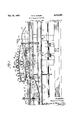
- Figure 1 is a view in side elevation of one end, the entering end, of a wrapping machine embodying my invention.
- Figure 2 is a similar view of the middle portion of the machine.
- Figure 3 is a similar view of the other end, of the machine.
- Figure 4 is a plan view of the portion of the machine shown in Fig. 1.
- Figure 5 is a plan view of the portion of the machine shown in Fig. 2.
- Figure 6 is a plan view of the portion of the machine shown in Fig. 3.
- Figure '7 is an enlarged fragmentary section taken at the line 1-1 on Fig. 6 and viewed in the direction of the arrows.
- Figure 8 is a similar view taken at the line 88 on Fig. 6 and viewed in the direction of the arrows.
- Figure 9 is a similar view taken at the line 99 on Fig. 6 and viewed in the direction of the arrows.
- Figure 10 is an enlarged broken longitudinal sectional view of the portion of the machine shown in Figs. 1 and 4, the section being taken at the irregular line Ill-40 on Fig. 4
- Figure 11 is a similar view, the section being taken at the line I I on Fig. 4 and viewed in the diand viewed in the rection of the arrow. 5
- Figure 12 is an enlarged sectional view of the machine, the section being taken at the line l2--l2 on Fig. 5 and viewed in the direction of the arrows.
- Figure 13 is a section taken at the line 13-18 on Fig. 5 and viewed in the direction of the arrows.
- Figure 14 is a section taken at the line i l-l4 on Fig. 6 and viewed in the direction of the arrows.
- Figure 15 is a section taken at the line Iii-l5 on' Fig. 6 and viewed in the direction of the arrows. 15
- Figure 16 is a section taken at the line l6l6 on Fig. 6 and viewed in the direction of the arrows.
- Figure 17 is an enlarged section taken at the line l.
- Figure 18 is a view in side elevation, but of reduced size, of the mechanism shown in Fig. 16.
- Figure 19 is a perspective view of the wrapped book.
- Figure 20 is a plan view of a portion of the machine of the preceding figures showing it as equipped. with members over which the wrappers are folded, the machine being shown as stripped of all of the parts thereof other than those which directly cooperate with the members referred to; 80 and Figure 21, a view like Fig. 15 showing the members referred to in Fig. 20, in place.
- the machine comprises, generally stated, an endless conveyor which extends lengthwise of the machine substantially throughout the length of the latter; wrapper-feeding mechanism 3
- means 31 for applying an adhesive, such as glue, to the underside of the part of the wrapper which extends below the book; means 38 forfolding the freeedge of the portion which extends over the top of the book around the underside of the book; means 39 for pressing the wrapped book at the portion thereof to which the adhesive is applied to insure proper adherence; means 40 for holding the book and wrapper from becoming disarranged while the means 31, 38 and 39'are operating; and means 4
- an adhesive such as glue
- sprocket chain 42 mounted at its opposite ends on sprockets 42 and 42 journaled on the stationary frame 43 of the machine, the chain being provided at intervals therealong with pairs of outwardly extending fingers 44, the fingers of each pair being spaced apart crosswise of the chain as shown in Fig. 17.
- the frame of the machine presents an upper bed portion formed at the entering end thereof of parallel bars 45' spaced apart and extending lengthwise of the machine and beyond these bars, in part, of plates, this bed being slotted lengthwise of the machine throughout the length of the conveyors 30 and 32 to permit the fingers 44 on the upper straight reach of the chain 42 and studs, hereinafter referred to, on the conveyor 32, to extend upwardly above the plane of the bed.
- the conveyor 30' is driven by the main drive shaft 46 journaled on the frame of the machine and shown as driven by .a motor 41 havingv sprocket-chain connection 48 with a'shaft 49 connected with the drive shaft 46 by speed-reducing mechanism indicated at 50.
- the drive from the drive shaft 46 to the conveyor 30 is through a helical gear 5
- the sheet conveyor 32 comprises a pair of sprocket chains 51 located at opposite sides of the conveyor 30 and each provided with a series of studs 58 hereinbefore referred to and extending outwardly therefrom and spaced apart the same distances as the fingers 44.
- the chains 51 are mounted at their ends on sprockets 59 and 60 carried by shafts BI and 62, respectively, journaled on the frame of the machine in such position that i the upper reaches of the chains 51 extend in sub- 'stantially the same horizontal plane as the upper reach of the chain 42, the chains 51 being driven in the same direction and at the same speed as the chain 42.
- the chains 51 are driven by the drive shaft 46 through a bevel gear 46 on the drive shaft 46 meshing with a bevel gear 63 on a jack-shaft 64 journaled on the machine frame and carrying a sprocket 65 connected by" a sprocket-chain '65 tion and therefore a general description thereof will suflice.
- This mechanism comprises a hopper rising from, the frame of the machine. shafts 99 are rotatably mounted in heads IOI,
- This feeder mechanism also comprises means operating to press the wrapper against the rolls 10 to insure the feeding of the Wrapper to the conveyor 32, these means comprising a roller 11 mounted on a lever 18 fulcrumed between its ends 19 on an arm extending from a rocli member 8 ⁇ actuated from the shaft 1! (by means not shown), a spring 82 yieldingly forcing the rollers 11 toward the rolls 10.
- the wrapper-feeding mechanism described operates to feed the wrappers one at a time to the bed of the machine and between stationary guides 85 thereon, into a position to be engaged at their rear edges by the studs 58 as the latter move up to the upper reach of the chains 51.
- the hopper 33 for the books represented at 86 comprises a bottom plate 81 slotted longitudinally of the machine as represented at 88 to receive the fingers 44, side-plates' ,89 secured to the bottom 81, a front plate 90'reaching short of the bottom of the hopper, rods 91 extending along the sides of'the plates 89' and connected therewith by clampbrackets 92 on rods 93 projecting outwardly from those plates, a rod 94' extending along the face of the front plate 90-and secured thereto by brackets 95 on which the plate 90 is vertically adjustable, in accordance with common practice, and to the ends ofthe rods 9
- the hopper structure described is supported for' vertical adjustment on the lower ends of threaded shafts 99 having screw-threaded engagement with the extensions 98, which latter slide on vertical posts I00 rigidly secured to, and The secured to the upper ends of the posts I00 and are provided with worm wheels I02 which mesh with worms I03 secured to a shaft I04 journaled in the heads 99 and extending crosswise of the 5;
- a handle I05 on the shaft I04 the latter may be rotated to bodily raise or lower the hopper, as desired, relative to the conveyor 30, depending on the direction in which this shaft is rotated.
- Hinged as represented at I06, to the edge of the hopper bottom 81 at the delivery side of the hopper are bars I01, shown as three in number, located side by side and spaced apart with the spaces therebetween in longitudinal alinement with the slots in the hopper 33, the bars I01, which form an extension of the hopper bottom 81, sloping toward the conveyors 30 and 32.
- the free ends of the two outer ones of the bars I01 are held in spaced relation to the conveyor 39 and the wrappers thereon as by means of rods I019 shown as extending through the guides I06 and secured at their upper ends to a cross bar I01".
- rotatable in clamp brackets I01 vertically adjustable on posts I01 rising from the frame of the machine at points laterally beyond the wrappers.
- the free end of the central one of the bars I01 is shown as provided with a roller I01 at which it rests on the conveyor 30 beneath it, the wrappers traveling under this roller.
- the bars I01 thus form a slideway along which the books, as they are conveyed from the hopper 33, travel in a downwardly inclined path to superposed position on the wrappers, the bars I01, by
- the fingers 44 in the operation of the conveyor 30 engage the rear edge of the lowermost book in the hopper 33 forcing it out/of the latter and onto the hopper-'bottom-extension I01- and between guide rails I06 carried by the two outside ones of the bars I01, the conveyor 30 in its continuing movement pushing the book from the hopper-bottom-extension I01 whereupon the book comes lightly to rest on the wrapper beneath it.
- the stud 58 by which the wrapper just referred to has been moved along the machine moves, in the movementof the chains 51 around the sprockets 60, out of engagement with the wrapper, whereupon the wrapper and the book thereon are advancedsolely by the conveyor 30.
- the book-hopper is located to one side of the center line of the machine so that the books are fed to such a position on the wrappers that the wrappers at one edge of the books extend therebeyond a short distance and at the other edge a relatively great distance, these extending portions of the wrapper-being represented at I09 and H0, respectively.
- the means 34 for folding the narrow extending portions I09 of the wrappers about the books comprise a flare device formed of a stationary plate III which extends at one end, II2, below the plane of the wrapper portion I09 and gradually curves upwardly and inwardly, in accordance with common practice, into substantially horizontal position directly above the book. as shown in Fig. 13.
- the folding means 35 for the wide extension portion IIO of the wrapper comprises a wire II3 supported on a' post II4 rising from the machine frame, one end II5 of the wire II3 extending beneath the wrapper portion 0. From this end the wire curves upwardly and inwardly as represented at II6 alongside of the holding means 36 and beyond these means inwardly and downwardly as shown at II1. Adjacent to, and below,
- the portion II 6 of the wire II 3 is a flare device H8 in the form of a plate one end II9 of which extends below thewrapper portion I I0 and gradually curves upwardly and inwardly to a position in which its other end I20 extends directly over the book.
- the holding means 36 for the books and wrappers comprises an endless chain I2I trained over sprockets I22 and, I23 rotatably mounted in a frame I24 supported, to be vertically adjustable in any desirable way, on a standard I25 rising from the frame of the machine, the chain I2I being provided at intervals along its length with outwardly extending pairs of lugs I26 spaced apart and equipped with rubber rolls I21 through which pins I28 loosely extend. Beyond each roll I21 is a cross pin I29 on the lugs I26 and extending laterally beyond the chain I 2I and adapted to ride on a ledge I30 secured to the frame I24.
- the chain, I2I is driven at the same surface speed as the conveyors 30 and 32 as by a sprocket chain I3I trained over a sprocket I32 rigidly connected with the sprocket I22, and a sprocket I33 connected with a shaft I34 driven as through a pair of'helical gears (not shown) by a shaft (not shown) having sprocket chain connection I35 with the drive shaft 46. 4
- the frame I24 would be adjusted vertically to a position, depending on the thickness of the books to be wrapped, in which, as the books pas beneath the lower reach of the chain I2I the rolls I21 will be forced upwardly against the pins I29 and therefore have no tendency to roll.
- the rolls I21 thus form a series of book-contacting surfaces a'plurality of which simultaneously press against'the book effecting a much more secure holding of the'book and wrapper against displacement than in the case of aconstruction having a continuous line bearing on the book as in the case of a chain directly engaging the book.
- the gluing mechanism 31 which is engaged by the wrapper after the latter has been folded about the book by the folding means 34 and 35 and as shown in Fig. 14,.
- a glue wheel I36 mounted-on a shaft I31 to engage the portion of the wrapper which extends beneath the book adiacent the edge of the latter over which the wrapper portion I09 is folded and apply a line of glue thereto, the wheel I36 extending into a body of glue in a pot thereof represented at I38.
- the drive for the shaft I 31 comprises a bevel gear I39 on the shaft I31 and meshing with a bevel gear I40 on a jack shaft MI, and a sprocket chain connection. I42 between .the shaft MI and the drive shaft 46.
- the folding means 38 comprise a plate I43 one endof which and represented at I44 extends horizontally over the part of the wide wrapper portion plate curving downwardly and inwardly as represented in Figs. 8, 9 and 15 intoa position in-which it extends substantially horizontally directly below the book thereby folding the wrapper into the final position shown in Fig. 16 this freeedge bf the wrapper becoming adhered to the strip of glue represented at I45 applied, to the underside of the wrapper which extends across the bottom of the book, by the gluing mechanism as above explained.
- presser mechanism 39 which is provided to insure the adhering of the free edge of the wrapper to the glue, it comprises the following described mechanism:
- a stationary bracket I46 Journaled on a stationary bracket I46,is a shaft I41 provided at one end with a gear I48 and at its opposite end with a sprocket I49, this sprocket extending upwardly into a position to be driven at its teeth by the pins which connect together the links of the feed conveyor 30.
- the gear I48 meshes with a pinion I50 journaled on the bracket I46 and meshing with a pinion I 5
- Pivoted at- I59 on the bracket I45 is an arm I54 carrying a roiler I 55 positioned directly above the roller I 52 and adapted to bear against the upper surface of the wrapped book, the roller I55 being connected with a pinion I55.
- the roller I55 is driven from the gear I5I through-the medium of meshing gears I51 and I59 which, respectively, mesh with the gears I5l and I55.
- the gears I51 and I59 arerotatably mounted on a bar I59 pivotally'connected at its upper and lower ends with the arm I54 and the bracket I45, respectively. through the medium of links I59 and I5I.
- a coil spring I62 connected at its opposite ends with studs I53 and I64 on the bracket I45 and the arm 1 I54, respectively, operates to force the roller III with yielding pressure toward the roller I52 to exert the desired rolling clamplng'pressure upon the glued edge of the wrapped book.
- the arm I54 is shown as provided with a screw device I55 having threaded engagement with the arm I54 for lengthwise adjustment and adapted-to bear at its lower end against the bracket I45, thereby permitting the operator to vary thedegree of clamping pressure exerted by the rollers.
- the mechanism 49 forpressing down on the book to hold it and the wrapper against accldental displacement while themechanisms 91, 38 and 99 are operating, is of the same construction as the mechanism above described, its frame portion represented at I55 and which is supported speeds of the chains I 99 and I11, for the purposes.
- the drive of the chain I59 is through-a sprocket chain I" trained overa sprocket I12 operatively connected with the sprocket I59 to rotate therewith and a-sprocket I13 secured to a shaft I14 driven, as through the medium of a pair of helical Sears (not shown) byv a sprocket I15 connected by a sprock t chain I19 witha sprocket on the drive shaft 4
- the feature of providing the book hopper as a structure vertically adjustable relative to the conveyor is of advantage not only because it permits 01' the machine being used for the wrapping of-books of greatly varying thicknesses, but also because it permits of the engagement of the fingers 44 with the edges of the books, for feeding them, throughout substantially the entire height of such edges regardless of the thicknesses of the books. .
- the books are of such character or size that they would become distorted out of flat condltion'in the folding of the wrappers about them, it is desirable that means he provided at the folding devices and over which the wrappers are folded to prevent the occurrence of such distortion.
- a wrapping machine the combination of g a hopper for the articles to be wrapped and having a slotted bottom, means for feeding the articls from said hopper to a wrapper beneath it, said hopper and means being relatively vertically adjustable for the purpose set forth, and means 55 of endless belts I92 supported at their opposite formingfia slideway for the articlesdischarging from the hopper inclining downwardly; therefrom ends on pulleys, the pulleys at one end being represented at I99 and secured to a shaft I94- driven by a sprocket chain I95 from a shaft I95 connected with the drive shaft 45 through the medium of meshing gears I91 and I89 on the shafts I 95 and 45, respectively.
- the chain I11 is driven through the medium of the shaft I14 to which the sprocket I19 is connected.
- the sprocket I13 being smaller than and flexibly connected at its upper end-with-said hopper.
- a wrapping machinathe combination 01 6 a hopper forthe articles to be wrapped and having a slotted bottom, means for feeding the artiis thus positioned to "resist 40 forming a slideway for the articles discharging oles from said hopper to a wrapper beneath it,
- said hopper and means being relatively vertically adjustable for the purpose set forth, a slideway for the' articles discharging from the hopper hinged to the hopper and inclining downwardly therefrom toward said first-named means, and means supporting the lower end of said slideway in spaced relation to said first-named means.
- a hopper for the articles to be wrapped having a slotted bottom
- means for feeding the articles from'said hopper to a wrapper beneath it said hopper and means being relatively vertically adjustable for the purpose set forth
- a slotted slideway for the articles discharging from the hopper hinged to the hopper and inclining downwardly therefrom toward said first-named means and means supporting the lower end of said slideway in spaced relation to said first-named means.
- a wrapping machine the combination of a hopper for the articles to be wrapped and having a slotted bottom, means for feeding the articles from said hopper to a wrapper beneath it, said hopper and means being'relatively vertically adjustable for the purpose set forth, a slideway for the articles discharging from the hopperhinged to the edge of the bottom of the hopper and inclining downwardly toward said first-named means, and means supporting the lower end of said slideway in spaced relation to said firstnamed means.
- a wrapping machine the combination of a hopper for the articles to be wrapped and having a slotted bottom, means for feeding the articles from said hopper to a wrapper beneath it, said hopper and means being relatively vertically adjustable for the purpose set forth, a slotted slideway for the articles discharging from the hopper hinged to the edge of the bottom of the hopper and inclining downwardly toward said first-named means, and means supporting the lower end of said slideway in spaced rlation to said first-named means.
- a wrappingmachine the combination of means for carrying the wrapper and the articles to be wrapped along the machine comprising a conveyor chain having projections thereon at in: tervals, means for "feeding wrappers in front ofsaid projections, means for feeding an article to each on the wrappers comprising a hopper located above said conveyor and having a slotted bottom' permitting passage of said projections, said hopper being vertically adjustable relative to said con-.
- a slideway for the articles discharging from the hopper hinged to the bottom of the hopperbottom and inclining downwardly toward said conveyor means spacing said slideway from said conveyor, meansloc'ated along the path of said conveyor for folding the wrappers about the articles and means for applying an adhesive to hold the wrappers in position on the articles.
- a conveyor comprising an endless element supported to travel around a circuit having an upper straight portion and having projections which, while traveling along said straight portion, are
- a conveyor comprising a chain driven around a circuit having an upper straight portion and comprising a sprocket at the end of said straight porof said conveyor at its terminal end, and means for driving said second conveyor faster than said first conveyor, said second conveyor having downwardly extending projections adapted to engage the rear margins of the wrapped articles carried by the projections on said first conveyor and move said wrapped articles ahead of said last-referredto projections before the latter move around said sprocket.
- a hopper for the articles to be wrapped and having a slotted-bottom, means for feeding the articles from said hopper to a wrapper beneath it, said hopper and means being relatively vertically adjustable for the purpose set forth, and slidewayforming means for the articles discharging from the hopper adapted to cause the articles to travel 55.
- said hop'per and means being relatively vertically adjustable for the purpose set forth, ,downward-' ly-inclined slidewaysforming means for the articles discharging from the hopper adapted to cause the articles to travel thereon downwardly thereon to the wrappers beneath them in the different relative adjustments of said hopper and first-named means, and means, permitting passage of the wrappersfor supporting the lower end of said slideway-forming means at substan- I5 tially the same elevation in the diiferent adjust wrappers, for supporting the lower end-of said slideway.
- a wrapping machine In a wrapping machine, the combination of ahopper for the articles to be wrapped and having a slotted bottom, means for feeding the arsis ' hopper, a-conveyor for said articles and wrappers,
- said hopper and means being relatively vertically adjustable for the purpose set f prth, means'forming a slideway for the articles discharging from the hopper hinged to said hopper and inclining downwardly therefrom and adjustable with said and roller means bearing on said conveyor for supporting the lower end of said slideway.
- the means for feeding work comprising wrappers and articles thereon to be wrapped, and. an endless element mounted to travel in an endless path and located above the workand having a plurality of widely spaced contacting elements adapted to directly engage with,- and produce substantially cup-like indentations in, the work at localized points thereon, for-the prrp'ose set forth.
- the combination of means for feeding work comprising wrappers and articles thereon to be wrapped, and an endless element mounted to travel in an endless path and located above the work. and having a plurality of widely spaced elastic contacting elements adapted to directly engage with, and produce substantially cup-like indentations in, the work at localized points thereon, for the purpose set forth.
- a wrapping machine the combination of means for feeding the work comprising wrappers and articles thereon to be wrapped, an endless element mounted to travel in an endless path and located above the work and having a plurality of widely spaced contacting elements adapted to directly engage with, and produce substantially cup-like indentations in, the work at localized points thereon, and means for driving said element in the direction of travel of said means and at substantially the same speed as said means.
- means for feeding the work comprising wrappers and articles thereon to be wrapped
- an endless element mounted to travel in an endless path and located above the work and having a plurality of widely spaced contacting elements adapted to directly engage with, and produce substantially cup-like indentations in, the work at localized points thereon, and means for driving said element in the direction of travel of said means and at substantially the same speed as said means.
- a wrapping machine the combination of means for carrying work comprising wrappers and articles thereon to be wrapped, along the machine and comprising a conveyor element having lugs at intervals thereon, means for feeding wrappers in front of said lugs, means for feeding the articles to said wrappers, wrapper-folding means located along the path of said conveyor element and having a plurality of widely spaced so contacting elements adapted to directly engage with, and produce substantially cup-like indentations in, the work at localized, points thereon for gripping the work between said conveyor element and said travelling element during the operation of said folding means, and means for applying an adhesive to the wrappers to hold them in position when folded about the articles.
- the combination of means for feeding work comprising wrappers and articles thereon to be wrapped, and, an endless element' separate from the work feeding means mounted to travel'in an endless path and located above the work and having a plurality of widely spaced contacting elements adapted to 70 directly engage with, and produce substantially cup-like indentations in, the work at localized RAYMOND E. acxmv; 5
Landscapes
- Engineering & Computer Science (AREA)
- Mechanical Engineering (AREA)
- Basic Packing Technique (AREA)
Description
R. E. ACKLEY FLAT WRAPPING MACHINE ll Sheets-Sheet 1 Filed July 16, 1932 Ocfi. 22, 1935. R ACKLEY 2,018,432
FLAT WRAPPING MACHINE Qct. 22, 1935. l R, E. ACKLEY I 2,013,432 FLAT WRAPPING momma; Filed Ju1y l6, 1932 ll Sheets-Sheet 3 Oct. 22, 1935. ACKLEY 2,018,432
' FLAT WRAPPING MACHINE Filed 'July 16, 1952 ll Sheets-Sheet 4 Fay/norm Herr-c2351:
Oct. 22, 1935. R. E. ACKLEY 2,013,432
FLAT WRAPPING "MACHINE Filed July 16-, 1932 11 Sheets-Sheet 5 w un Oct. 22, 1935. R. E. ACKLEY 2,018,432
FLAT WRAPPING MACHINE Filed July 16, 1932 1 1 sheets-sheet 6 E. ACKLE"! FLAT W HAPPING MACHINE Til Sheets$heet 7 Oct, 22, 1935.
v "R. E. ACKLEY FLAT WRAPPING MACHINE Filed July 16, 1932 11 She ets-Sheet 8 @645. 22 1935. E ACKLEY 2,018,432
FLAT WRAPPING MACHINE Filed July 16, 1952 ll Sheets-Sheet 9 IIIIIIIII,
iaw si-in w, y a. ACKLEY ,9
FLAT WRAPPING MACHINE Filed July 16, 1932 11 Sheets-Sheet l0 Oct. '22, 1935. R. E. ACKLEY 2,018,432
FLAT WRAPPING MACHINE Filed July 16, '1932 l1 Sheets-Sheet l1 Patented Oct. 22, 1935 FLAT WRAPPING MACHINE Raymond E. Ackley, Chicago, Ill., assignor to R. R. Donnelley & Sons 00., Chicago, 11]., a cor-- poration of Illinois Application July 16, 1932, Serial No. 622,935
24 Claims.
My invention relates more particularly to machines for wrapping articles, and [particularly books, in flat condition and my, primary object, generally stated, is. to provide improvements in machines of this general character whereby they will be caused to function to better advantage.
Certain of my more specific objects are to provide improvements to the end that the books supplied to a hop-per will be positively fed therefrom and without ruffiing of the pages thereof; to pro-,
vide simple and effective means whereby themachine will be adapted for the feeding, from the hopper, of articles of widely varying thicknesses; to provide for the depositing of the articles on the wrappers in such a way as to insure the proper positioning of the articles relative thereto and without displacement of I the wrappers; to provide improvements in the means for holding the articles and wrappers against displacement in the feeding operation and while being operated on as for example by the folding devices; to provide improved means for insuring the proper adhesion of the wrappers, folded about the articles, at the glued joints thereof; to provide in a'machine involving an endless conveyor having projections which advance the articles and wrappers and means which move the wrapped articles beyond the projections, improvements in the means last referred to for insuring against damage to the wrapped articles by the projections in the movement thereof out of the feeding plane; and to provide for the novel folding of the wrappers about the articles and the location of the lines of adhesion of the free edges ,of the wrappers to the portions thereof which these free edges overlie.
Referring to the accompanying drawings:
Figure 1 is a view in side elevation of one end, the entering end, of a wrapping machine embodying my invention.
Figure 2 is a similar view of the middle portion of the machine.
Figure 3 is a similar view of the other end, of the machine.
Figure 4 is a plan view of the portion of the machine shown in Fig. 1.
Figure 5 is a plan view of the portion of the machine shown in Fig. 2.
Figure 6 is a plan view of the portion of the machine shown in Fig. 3.
Figure '7 is an enlarged fragmentary section taken at the line 1-1 on Fig. 6 and viewed in the direction of the arrows.
Figure 8 is a similar view taken at the line 88 on Fig. 6 and viewed in the direction of the arrows.
Figure 9 is a similar view taken at the line 99 on Fig. 6 and viewed in the direction of the arrows.
Figure 10 is an enlarged broken longitudinal sectional view of the portion of the machine shown in Figs. 1 and 4, the section being taken at the irregular line Ill-40 on Fig. 4
direction of the arrows.
Figure 11 is a similar view, the section being taken at the line I I on Fig. 4 and viewed in the diand viewed in the rection of the arrow. 5
Figure 12 is an enlarged sectional view of the machine, the section being taken at the line l2--l2 on Fig. 5 and viewed in the direction of the arrows.
Figure 13 is a section taken at the line 13-18 on Fig. 5 and viewed in the direction of the arrows.
Figure 14 is a section taken at the line i l-l4 on Fig. 6 and viewed in the direction of the arrows.
Figure 15 is a section taken at the line Iii-l5 on' Fig. 6 and viewed in the direction of the arrows. 15
Figure 16 is a section taken at the line l6l6 on Fig. 6 and viewed in the direction of the arrows.
Figure 17 is an enlarged section taken at the line l.|l'| on Fig. 1 and viewed in the direction of the arrows.
Figure 18 is a view in side elevation, but of reduced size, of the mechanism shown in Fig. 16.
Figure 19 is a perspective view of the wrapped book.
Figure 20 is a plan view of a portion of the machine of the preceding figures showing it as equipped. with members over which the wrappers are folded, the machine being shown as stripped of all of the parts thereof other than those which directly cooperate with the members referred to; 80 and Figure 21, a view like Fig. 15 showing the members referred to in Fig. 20, in place.
As a preface to the following description of the illustrated machine it may be stated it'is of the 35 type involving the feeding of wrappers'and books, the latter to superposed position on the wrappers, and the moving of the assembled wrappers and books into position for the folding of the wrappers about the books and the securing of the wrappers 40 in position.
Referring to the details of the illustrated machine as shown in Figs. 1-18, inclusive, the machine comprises, generally stated, an endless conveyor which extends lengthwise of the machine substantially throughout the length of the latter; wrapper-feeding mechanism 3| at the entering end of the machine; an endless wrapperconveyor 32 paralleling the conveyor 30 and conveying the wrappers to a position in which the conveyor 30 engages them; a hopper 33 for the books and from which the latter are fed by the conveyor 30 to superposed position on the wrappers, the conveyor 30 thereafter advancing the assembled books and wrappers; means 34 for folding the narrow edge portion of the wrapper about the book; means 35 for folding the wide edge portion of the wrapper across the top of the book; means 33 for holding the book and wrapper, while moving and operated on by the means 34 and 35,
from being disarranged; means 31 for applying an adhesive, such as glue, to the underside of the part of the wrapper which extends below the book; means 38 forfolding the freeedge of the portion which extends over the top of the book around the underside of the book; means 39 for pressing the wrapped book at the portion thereof to which the adhesive is applied to insure proper adherence; means 40 for holding the book and wrapper from becoming disarranged while the means 31, 38 and 39'are operating; and means 4| for advancing the wrapped book relative to the conveyor 30 to insure proper disengagement from the wrapped book of the portions of the conveyor 30 by which the wrapped book is fed.
Referring to the conveyor 33 it is shown as in the form of a sprocket chain 42 mounted at its opposite ends on sprockets 42 and 42 journaled on the stationary frame 43 of the machine, the chain being provided at intervals therealong with pairs of outwardly extending fingers 44, the fingers of each pair being spaced apart crosswise of the chain as shown in Fig. 17.
The frame of the machine presents an upper bed portion formed at the entering end thereof of parallel bars 45' spaced apart and extending lengthwise of the machine and beyond these bars, in part, of plates, this bed being slotted lengthwise of the machine throughout the length of the conveyors 30 and 32 to permit the fingers 44 on the upper straight reach of the chain 42 and studs, hereinafter referred to, on the conveyor 32, to extend upwardly above the plane of the bed.
The conveyor 30' is driven by the main drive shaft 46 journaled on the frame of the machine and shown as driven by .a motor 41 havingv sprocket-chain connection 48 with a'shaft 49 connected with the drive shaft 46 by speed-reducing mechanism indicated at 50. The drive from the drive shaft 46 to the conveyor 30 is through a helical gear 5| on the shaft 46 meshing with a helical gear 52 on a vertical shaft 53 rotatably mounted on' the machine-frame, the shaft 53 being provided at its upper end with a helical gear 54 meshing with a second helical gear 55 rigid with a shaft 56 journaled on the machine-frame andto which the sprocket 42 is secured.
The sheet conveyor 32 comprises a pair of sprocket chains 51 located at opposite sides of the conveyor 30 and each provided with a series of studs 58 hereinbefore referred to and extending outwardly therefrom and spaced apart the same distances as the fingers 44. The chains 51 are mounted at their ends on sprockets 59 and 60 carried by shafts BI and 62, respectively, journaled on the frame of the machine in such position that i the upper reaches of the chains 51 extend in sub- 'stantially the same horizontal plane as the upper reach of the chain 42, the chains 51 being driven in the same direction and at the same speed as the chain 42.
- The chains 51 are driven by the drive shaft 46 through a bevel gear 46 on the drive shaft 46 meshing with a bevel gear 63 on a jack-shaft 64 journaled on the machine frame and carrying a sprocket 65 connected by" a sprocket-chain '65 tion and therefore a general description thereof will suflice. This mechanism comprises a hopper rising from, the frame of the machine. shafts 99 are rotatably mounted in heads IOI,
59, to receive the pile of wrappers, located at the entering end of the machine and above feed rolls 10 mounted on a shaft 1I driven by a sprocket chain 12 connected with sprockets 13 and 14 on the shafts 1| and 64, respectively. Located adjacent the bottom of the hopper 69 which is open at its discharge end are suction devices one of which is shown at 15. mounted to be raised into engagement'with the lowermost wrapper and lowered to draw the edge of the wrapper into engagement with the rolls 10, by mechanism driven by a cam 16 on the shaft 1 I.
This feeder mechanism also comprises means operating to press the wrapper against the rolls 10 to insure the feeding of the Wrapper to the conveyor 32, these means comprising a roller 11 mounted on a lever 18 fulcrumed between its ends 19 on an arm extending from a rocli member 8} actuated from the shaft 1! (by means not shown), a spring 82 yieldingly forcing the rollers 11 toward the rolls 10. A separating and time by the suction meansreferred to and exerts Y a lifting force on the wrappers above it to facilitate the feeding of the lower wrapper.
The wrapper-feeding mechanism described operates to feed the wrappers one at a time to the bed of the machine and between stationary guides 85 thereon, into a position to be engaged at their rear edges by the studs 58 as the latter move up to the upper reach of the chains 51.
- The hopper 33 for the books represented at 86, (Figs. 1, 4, 11 and 17) comprises a bottom plate 81 slotted longitudinally of the machine as represented at 88 to receive the fingers 44, side-plates' ,89 secured to the bottom 81, a front plate 90'reaching short of the bottom of the hopper, rods 91 extending along the sides of'the plates 89' and connected therewith by clampbrackets 92 on rods 93 projecting outwardly from those plates, a rod 94' extending along the face of the front plate 90-and secured thereto by brackets 95 on which the plate 90 is vertically adjustable, in accordance with common practice, and to the ends ofthe rods 9| by clamp brackets 96, and a bar 91 having extensions 98 at its ends to which the rods 9| are connected.
The hopper structure described is supported for' vertical adjustment on the lower ends of threaded shafts 99 having screw-threaded engagement with the extensions 98, which latter slide on vertical posts I00 rigidly secured to, and The secured to the upper ends of the posts I00 and are provided with worm wheels I02 which mesh with worms I03 secured to a shaft I04 journaled in the heads 99 and extending crosswise of the 5;
machine. By means of a handle I05 on the shaft I04 the latter may be rotated to bodily raise or lower the hopper, as desired, relative to the conveyor 30, depending on the direction in which this shaft is rotated.
Hinged as represented at I06, to the edge of the hopper bottom 81 at the delivery side of the hopper are bars I01, shown as three in number, located side by side and spaced apart with the spaces therebetween in longitudinal alinement with the slots in the hopper 33, the bars I01, which form an extension of the hopper bottom 81, sloping toward the conveyors 30 and 32. The free ends of the two outer ones of the bars I01 are held in spaced relation to the conveyor 39 and the wrappers thereon as by means of rods I019 shown as extending through the guides I06 and secured at their upper ends to a cross bar I01". rotatable in clamp brackets I01 vertically adjustable on posts I01 rising from the frame of the machine at points laterally beyond the wrappers. The free end of the central one of the bars I01 is shown as provided with a roller I01 at which it rests on the conveyor 30 beneath it, the wrappers traveling under this roller. The bars I01 thus form a slideway along which the books, as they are conveyed from the hopper 33, travel in a downwardly inclined path to superposed position on the wrappers, the bars I01, by
being hinged to the hopper, automatically adjusting themselves in the adjusting of the hopper 33 vertically.
The fingers 44 in the operation of the conveyor 30 engage the rear edge of the lowermost book in the hopper 33 forcing it out/of the latter and onto the hopper-'bottom-extension I01- and between guide rails I06 carried by the two outside ones of the bars I01, the conveyor 30 in its continuing movement pushing the book from the hopper-bottom-extension I01 whereupon the book comes lightly to rest on the wrapper beneath it. Following the operation just described the stud 58 by which the wrapper just referred to has been moved along the machine, moves, in the movementof the chains 51 around the sprockets 60, out of engagement with the wrapper, whereupon the wrapper and the book thereon are advancedsolely by the conveyor 30.
-As shown the book-hopper is located to one side of the center line of the machine so that the books are fed to such a position on the wrappers that the wrappers at one edge of the books extend therebeyond a short distance and at the other edge a relatively great distance, these extending portions of the wrapper-being represented at I09 and H0, respectively.
The means 34 for folding the narrow extending portions I09 of the wrappers about the books comprise a flare device formed of a stationary plate III which extends at one end, II2, below the plane of the wrapper portion I09 and gradually curves upwardly and inwardly, in accordance with common practice, into substantially horizontal position directly above the book. as shown in Fig. 13.
The folding means 35 for the wide extension portion IIO of the wrapper comprises a wire II3 supported on a' post II4 rising from the machine frame, one end II5 of the wire II3 extending beneath the wrapper portion 0. From this end the wire curves upwardly and inwardly as represented at II6 alongside of the holding means 36 and beyond these means inwardly and downwardly as shown at II1. Adjacent to, and below,
the portion II 6 of the wire II 3 is a flare device H8 in the form of a plate one end II9 of which extends below thewrapper portion I I0 and gradually curves upwardly and inwardly to a position in which its other end I20 extends directly over the book.
It will be manifest from the foregoing that as the wrapper moves over the guide wire II3 its wide portion IIO will be folded upwardly and inwardly around the adjacent edge of the book,
the flare device II8 operating close to the edge The holding means 36 for the books and wrappers comprises an endless chain I2I trained over sprockets I22 and, I23 rotatably mounted in a frame I24 supported, to be vertically adjustable in any desirable way, on a standard I25 rising from the frame of the machine, the chain I2I being provided at intervals along its length with outwardly extending pairs of lugs I26 spaced apart and equipped with rubber rolls I21 through which pins I28 loosely extend. Beyond each roll I21 is a cross pin I29 on the lugs I26 and extending laterally beyond the chain I 2I and adapted to ride on a ledge I30 secured to the frame I24.
The chain, I2I is driven at the same surface speed as the conveyors 30 and 32 as by a sprocket chain I3I trained over a sprocket I32 rigidly connected with the sprocket I22, and a sprocket I33 connected with a shaft I34 driven as through a pair of'helical gears (not shown) by a shaft (not shown) having sprocket chain connection I35 with the drive shaft 46. 4
In practice the frame I24 would be adjusted vertically to a position, depending on the thickness of the books to be wrapped, in which, as the books pas beneath the lower reach of the chain I2I the rolls I21 will be forced upwardly against the pins I29 and therefore have no tendency to roll. The rolls I21 thus form a series of book-contacting surfaces a'plurality of which simultaneously press against'the book effecting a much more secure holding of the'book and wrapper against displacement than in the case of aconstruction having a continuous line bearing on the book as in the case of a chain directly engaging the book. The gluing mechanism 31 which is engaged by the wrapper after the latter has been folded about the book by the folding means 34 and 35 and as shown in Fig. 14,. comprises a glue wheel I36 mounted-on a shaft I31 to engage the portion of the wrapper which extends beneath the book adiacent the edge of the latter over which the wrapper portion I09 is folded and apply a line of glue thereto, the wheel I36 extending into a body of glue in a pot thereof represented at I38.
The drive for the shaft I 31 comprises a bevel gear I39 on the shaft I31 and meshing with a bevel gear I40 on a jack shaft MI, and a sprocket chain connection. I42 between .the shaft MI and the drive shaft 46. The folding means 38 comprise a plate I43 one endof which and represented at I44 extends horizontally over the part of the wide wrapper portion plate curving downwardly and inwardly as represented in Figs. 8, 9 and 15 intoa position in-which it extends substantially horizontally directly below the book thereby folding the wrapper into the final position shown in Fig. 16 this freeedge bf the wrapper becoming adhered to the strip of glue represented at I45 applied, to the underside of the wrapper which extends across the bottom of the book, by the gluing mechanism as above explained.
Referring now to the presser mechanism 39 which is provided to insure the adhering of the free edge of the wrapper to the glue, it comprises the following described mechanism:
Journaled on a stationary bracket I46,is a shaft I41 provided at one end with a gear I48 and at its opposite end with a sprocket I49, this sprocket extending upwardly into a position to be driven at its teeth by the pins which connect together the links of the feed conveyor 30. The gear I48 meshes with a pinion I50 journaled on the bracket I46 and meshing with a pinion I 5| also journaled on the bracket us and connected-witharollerI52" the sprocket m whereby the desired surface located below the wrapped book at its'glued edge (Fig. 16).
Pivoted at- I59 on the bracket I45 is an arm I54 carrying a roiler I 55 positioned directly above the roller I 52 and adapted to bear against the upper surface of the wrapped book, the roller I55 being connected with a pinion I55. The roller I55 is driven from the gear I5I through-the medium of meshing gears I51 and I59 which, respectively, mesh with the gears I5l and I55. The gears I51 and I59 arerotatably mounted on a bar I59 pivotally'connected at its upper and lower ends with the arm I54 and the bracket I45, respectively. through the medium of links I59 and I5I. A coil spring I62, connected at its opposite ends with studs I53 and I64 on the bracket I45 and the arm 1 I54, respectively, operates to force the roller III with yielding pressure toward the roller I52 to exert the desired rolling clamplng'pressure upon the glued edge of the wrapped book. The arm I54 is shown as provided with a screw device I55 having threaded engagement with the arm I54 for lengthwise adjustment and adapted-to bear at its lower end against the bracket I45, thereby permitting the operator to vary thedegree of clamping pressure exerted by the rollers.
The mechanism 49 forpressing down on the book to hold it and the wrapper against accldental displacement while themechanisms 91, 38 and 99 are operating, is of the same construction as the mechanism above described, its frame portion represented at I55 and which is supported speeds of the chains I 99 and I11, for the purposes.
' above stated, are effected.
on the frame of the machine to be vertically 'adjustable, being provided with sprockets I51 and I68 over which the endless sprocket chain I59 provided with spaced apart book-contacting members I19 as explained of the mechanism 95, is trained. The drive of the chain I59 is through-a sprocket chain I" trained overa sprocket I12 operatively connected with the sprocket I59 to rotate therewith and a-sprocket I13 secured to a shaft I14 driven, as through the medium of a pair of helical Sears (not shown) byv a sprocket I15 connected by a sprock t chain I19 witha sprocket on the drive shaft 4 The mechanism H for engaging the wrapped books to advance them away from the fingers 44 by which they are conveyed as abovedescribed,
comprises an endless chain I11 trained over sprocketsJn and I19 rot atablymounted'in a .frame 199 supported at a side thereof on the frame .of the machine. 1 The chain I11 which extends in longitudinal allnement with the conextending I9I whichare adapted in the operation of the machine topass between the fingers therebyinsuring a clearance between the fingers "veyor 99. isiiii'ovided at'intervals with outwardly The feature of providing the book hopper as a structure vertically adjustable relative to the conveyor is of advantage not only because it permits 01' the machine being used for the wrapping of-books of greatly varying thicknesses, but also because it permits of the engagement of the fingers 44 with the edges of the books, for feeding them, throughout substantially the entire height of such edges regardless of the thicknesses of the books. .Where the books are of such character or size that they would become distorted out of flat condltion'in the folding of the wrappers about them, it is desirable that means he provided at the folding devices and over which the wrappers are folded to prevent the occurrence of such distortion. In Figs. 20 and 21 a modification of the machine of the preceding figures and incorporating means for the purpose just referred to, is illustrated, this modified machine being identical I with the machine of the preceding figures except for the addition of means as above referred to 5 7 shown as comprising two stripllke metal members I99 and I99 which extend lengthwise of the machine and overlie the.longitudinal edges of the books as they pass between them, these members being each supported at one end only as by brackets I9I and I92, respectively, which rise from the machine frame at points beyond the opposite longitudinal edges of the wrappers, the other ends of the members I99 and I99 being unsupported. The members I99 and I99 are flexible at their free ends in a vertical direction, viz., in a direction parallel to the folds, but relatively rigid in a horizontal direction, viz., in a direction normal to the folds.
The member 199 lateral pressure which would be applied against the book in the wrapping of the wrapper portion of the book and the member I99 serving to .resist 44and the rear edge of the book in the movechain I11 delivering the wrappedbooks, as to an 05 endless belt conveyor shown-as comprising a'series lateral force which would be directed against the book in the folding of the wrapper portion III] about the other edge of thebook by the folding means". v 50 While I have illustrated and described certain particular embodiments of my invention, I do, not wish to be understood as intending to limit it thereto asthe invention may be embodied in other forms of structure and the constructions shown variously modified and altered without departing from the spirit of my invention. What I claim as new, and desire to secure by Letters Patent, is: 1
1. In a wrapping machine, the combination of g a hopper for the articles to be wrapped and having a slotted bottom, means for feeding the articls from said hopper to a wrapper beneath it, said hopper and means being relatively vertically adjustable for the purpose set forth, and means 55 of endless belts I92 supported at their opposite formingfia slideway for the articlesdischarging from the hopper inclining downwardly; therefrom ends on pulleys, the pulleys at one end being represented at I99 and secured to a shaft I94- driven by a sprocket chain I95 from a shaft I95 connected with the drive shaft 45 through the medium of meshing gears I91 and I89 on the shafts I 95 and 45, respectively.
The chain I11 is driven through the medium of the shaft I14 to which the sprocket I19 is connected. the sprocket I13 being smaller than and flexibly connected at its upper end-with-said hopper. r
2. In a wrapping machinathe combination 01 6 a hopper forthe articles to be wrapped and having a slotted bottom, means for feeding the artiis thus positioned to "resist 40 forming a slideway for the articles discharging oles from said hopper to a wrapper beneath it,
said hopper and means being relatively vertically adjustable for the purpose set forth, a slideway for the' articles discharging from the hopper hinged to the hopper and inclining downwardly therefrom toward said first-named means, and means supporting the lower end of said slideway in spaced relation to said first-named means.
4. In a wrapping machine, the combination of a hopper for the articles to be wrapped and having a slotted bottom, means for feeding the articles from'said hopper to a wrapper beneath it, said hopper and means being relatively vertically adjustable for the purpose set forth, a slotted slideway for the articles discharging from the hopper hinged to the hopper and inclining downwardly therefrom toward said first-named means, and means supporting the lower end of said slideway in spaced relation to said first-named means.
5. In a wrapping machine, the combination of a hopper for the articles to be wrapped and having a slotted bottom, means for feeding the articles from said hopper to a wrapper beneath it, said hopper and means being'relatively vertically adjustable for the purpose set forth, a slideway for the articles discharging from the hopperhinged to the edge of the bottom of the hopper and inclining downwardly toward said first-named means, and means supporting the lower end of said slideway in spaced relation to said firstnamed means.
- 6. In a wrapping machine, the combination of a hopper for the articles to be wrapped and having a slotted bottom, means for feeding the articles from said hopper to a wrapper beneath it, said hopper and means being relatively vertically adjustable for the purpose set forth, a slotted slideway for the articles discharging from the hopper hinged to the edge of the bottom of the hopper and inclining downwardly toward said first-named means, and means supporting the lower end of said slideway in spaced rlation to said first-named means.
7. In a wrappingmachine the combination of means for carrying the wrapper and the articles to be wrapped along the machine comprising a conveyor chain having projections thereon at in: tervals, means for "feeding wrappers in front ofsaid projections, means for feeding an article to each on the wrappers comprising a hopper located above said conveyor and having a slotted bottom' permitting passage of said projections, said hopper being vertically adjustable relative to said con-.
veyor, a slideway for the articles discharging from the hopper hinged to the bottom of the hopperbottom and inclining downwardly toward said conveyor, means spacing said slideway from said conveyor, meansloc'ated along the path of said conveyor for folding the wrappers about the articles and means for applying an adhesive to hold the wrappers in position on the articles. n
8 In a wrapping machine, the combination of a conveyor comprising an endless element supported to travel around a circuit having an upper straight portion and having projections which, while traveling along said straight portion, are
adapted to push wrappers and articles thereon tending at substantially the same elevation in the different adjustments of said hopper.
' portion for wrapping the wrappers around the articles, a second conveyor beyond said means and overlying said straight portion and having projections adapted to engage the rear edges of 'wrapped articles carried by the projections on 5 said first-named conveyor, and means for driving said second conveyor faster than said first-named conveyor for moving the articles ahead of the projections on said first-named conveyor before the last-referred-to projections move substan- 1 tially away from said straight portion.
9. In a wrapping machine, the combination of a conveyor comprising a chain driven around a circuit having an upper straight portion and comprising a sprocket at the end of said straight porof said conveyor at its terminal end, and means for driving said second conveyor faster than said first conveyor, said second conveyor having downwardly extending projections adapted to engage the rear margins of the wrapped articles carried by the projections on said first conveyor and move said wrapped articles ahead of said last-referredto projections before the latter move around said sprocket.
10. In a wrapping machine, the combination of means for feeding wrappers and articles there- 85 on to be wrapped, means for folding one. edge of the wrappers about one edge of the articles and across the upper faces thereof to extend beyond the opposite edge of the articles, means for applying adhesive near the edges of the wrappers 4,0,
which underlie the articles and adjacent the edges of the articles about which the final folds of the wrappers are to be made, and means for folding said extending edges of the wrappers around said last-referred-to edges of the articles and upwardly against the adhesive applied by said third-named means.
11. In a wrapping machine, the combination of a hopper for the articles to be wrapped and having a slotted-bottom, means for feeding the articles from said hopper to a wrapper beneath it, said hopper and means being relatively vertically adjustable for the purpose set forth, and slidewayforming means for the articles discharging from the hopper adapted to cause the articles to travel 55.
thereon downwardly to the wrappers beneath -them-in the different relative adjustments of the hopper and said first-named means, the end of said last-named means adjacent the wrapper ex- 12. In awrapplng machine, the combination of a hopper for the articles to be wrapped and hav-, ing aslotted bottom, means for feeding the articles from said hopper to wrappers beneath it,
I said hop'per and means being relatively vertically adjustable for the purpose set forth, ,downward-' ly-inclined slidewaysforming means for the articles discharging from the hopper adapted to cause the articles to travel thereon downwardly thereon to the wrappers beneath them in the different relative adjustments of said hopper and first-named means, and means, permitting passage of the wrappersfor supporting the lower end of said slideway-forming means at substan- I5 tially the same elevation in the diiferent adjust wrappers, for supporting the lower end-of said slideway.
'14. In a wrapping machine, the combination of ahopper for the articles to be wrapped and having a slotted bottom, means for feeding the arsis ' hopper, a-conveyor for said articles and wrappers,
ticles from said hopper to wrappers beneath it, said hopper and means being relatively vertically adjustable for the purpose set f prth, means'forming a slideway for the articles discharging from the hopper hinged to said hopper and inclining downwardly therefrom and adjustable with said and roller means bearing on said conveyor for supporting the lower end of said slideway.
15. In a machine. of the character set forth,
" the combination of means for feeding a wrapper with the article thereon to be wrapped, means for folding one end of the wrapper about the article to initiate the wrap, means narrower than said article for conveying said article with initial "wrap, means operating upon the margins of said article and wrapper which extend beyond said conveying means one for applying adhesive for holding the wrapper in position on said article and the other for completing the folding of said wrapper about said article, and rollers between which said extended margins of article and wrapper pass operating to roll down the joint-at the adhesive for securing better adhesion. 16. In a machine of the character set forth, the combination of means for feeding a wrapper with the article thereon to be wrapped, means for folding one end of the wrapper about the article to, initiate the wrap, means narrower than said article for conveying said article with initial wrap, means operating upon-the margins of said article and wrapper which extend beyond said conveying means one for applying adhesive for holding the wrapper in position on said article and the other for completing the folding of said wrapper about said article, and positively driven rollers between which said extended margins of article and wrapper pass operating to-rolldown the joint at the adhesive for securing better adhesion.
17. In a wrapping machine, the means for feeding work comprising wrappers and articles thereon to be wrapped, and. an endless element mounted to travel in an endless path and located above the workand having a plurality of widely spaced contacting elements adapted to directly engage with,- and produce substantially cup-like indentations in, the work at localized points thereon, for-the prrp'ose set forth.
18. In a wrapping machine, the combination of means for feeding work comprising wrappers and articles thereon to be wrapped, and an endless element mounted to travel in an endless path and located above the work. and having a plurality of widely spaced elastic contacting elements adapted to directly engage with, and produce substantially cup-like indentations in, the work at localized points thereon, for the purpose set forth.
combination of I points thereon, for the purpose set forth.
19. In a wrapping machine, the combination of means for feeding work comprising wrappers and articles thereon to be wrapped, and an endless element mounted to travel in an endless path and located above the work and having-a plurality of elastic rolls adapted to directly engage with, and produce substantially cup-like indentations in, the work at localized points thereon, for the purpose set forth.
20. In a wrapping machine, the combination of means for feeding the work comprising wrappers and articles thereon to be wrapped, an endless element mounted to travel in an endless path and located above the work and having a plurality of widely spaced contacting elements adapted to directly engage with, and produce substantially cup-like indentations in, the work at localized points thereon, and means for driving said element in the direction of travel of said means and at substantially the same speed as said means. W
21. In a wrapping machine, the combination of means for carrying work comprising wrappers and articles thereon to be wrapped, along the machine and comprising a conveyor element having lugs at intervals thereon, means for feeding wrappers in front of said lugs, means for feeding the articles to said wrappers, wrapper-folding means located along the path of said conveyor element and having a plurality of widely spaced so contacting elements adapted to directly engage with, and produce substantially cup-like indentations in, the work at localized, points thereon for gripping the work between said conveyor element and said travelling element during the operation of said folding means, and means for applying an adhesive to the wrappers to hold them in position when folded about the articles.
22. Ina wrapping machine, the combination of means for feeding work comprising wrappers and articlesthereon to be wrapped, and an endless element mounted to travel in an endless path and located above the work andhaving a plurality of widely spaced contacting elements adapted to directly engage with, and produce substantially cup-like indentations in, the work at localized points thereon, for the purpose of preventing slippage of the work relative to said feeding means while they are being operated on by other mechanisms.
23. In a wrapping machine, the combination of wrapping means; a conveyor carrying impelling means for moving a wrapper and an obiect to be wrapped in overlying relation one to the other past said wrapping means; means d1- the assembly.
' 24. In a wrapping machine, the combination of means for feeding work comprising wrappers and articles thereon to be wrapped, and, an endless element' separate from the work feeding means mounted to travel'in an endless path and located above the work and having a plurality of widely spaced contacting elements adapted to 70 directly engage with, and produce substantially cup-like indentations in, the work at localized RAYMOND E. acxmv; 5
rectly contacting one side of said assembled wrap-'
Priority Applications (1)
| Application Number | Priority Date | Filing Date | Title |
|---|---|---|---|
| US622935A US2018432A (en) | 1932-07-16 | 1932-07-16 | Flat wrapping machine |
Applications Claiming Priority (1)
| Application Number | Priority Date | Filing Date | Title |
|---|---|---|---|
| US622935A US2018432A (en) | 1932-07-16 | 1932-07-16 | Flat wrapping machine |
Publications (1)
| Publication Number | Publication Date |
|---|---|
| US2018432A true US2018432A (en) | 1935-10-22 |
Family
ID=24496108
Family Applications (1)
| Application Number | Title | Priority Date | Filing Date |
|---|---|---|---|
| US622935A Expired - Lifetime US2018432A (en) | 1932-07-16 | 1932-07-16 | Flat wrapping machine |
Country Status (1)
| Country | Link |
|---|---|
| US (1) | US2018432A (en) |
Cited By (11)
| Publication number | Priority date | Publication date | Assignee | Title |
|---|---|---|---|---|
| US2590351A (en) * | 1948-01-07 | 1952-03-25 | Clarence J Russell | Magazine wrapping machine |
| US2643498A (en) * | 1951-02-27 | 1953-06-30 | Eastern Res Lab Inc | Label affixing machine |
| US2651899A (en) * | 1950-04-20 | 1953-09-15 | Hall Printing Co W F | Book and wrapper feed mechanism for wrapping machines |
| US2719392A (en) * | 1952-07-19 | 1955-10-04 | Colonial Press Inc | Apparatus for packaging books in cartons |
| US2737002A (en) * | 1950-12-01 | 1956-03-06 | Internat Packaging Corp | Packaging machine |
| US2820230A (en) * | 1956-01-27 | 1958-01-21 | Thomas G Maloney | Machine for casing-in books |
| US2860461A (en) * | 1955-01-21 | 1958-11-18 | Fed Paper Board Co Inc | Can packaging apparatus |
| US2898720A (en) * | 1955-06-08 | 1959-08-11 | Masonite Corp | Wrapping machine |
| US2903830A (en) * | 1954-11-24 | 1959-09-15 | Hickok W O Mfg Co | Banding machine |
| US3019577A (en) * | 1958-09-09 | 1962-02-06 | United States Steel Corp | Packaging line |
| US5197260A (en) * | 1988-10-31 | 1993-03-30 | L Emballage Carton Sa (Societe Anonyme) | Method for packing articles, and machine for performing the method |
-
1932
- 1932-07-16 US US622935A patent/US2018432A/en not_active Expired - Lifetime
Cited By (11)
| Publication number | Priority date | Publication date | Assignee | Title |
|---|---|---|---|---|
| US2590351A (en) * | 1948-01-07 | 1952-03-25 | Clarence J Russell | Magazine wrapping machine |
| US2651899A (en) * | 1950-04-20 | 1953-09-15 | Hall Printing Co W F | Book and wrapper feed mechanism for wrapping machines |
| US2737002A (en) * | 1950-12-01 | 1956-03-06 | Internat Packaging Corp | Packaging machine |
| US2643498A (en) * | 1951-02-27 | 1953-06-30 | Eastern Res Lab Inc | Label affixing machine |
| US2719392A (en) * | 1952-07-19 | 1955-10-04 | Colonial Press Inc | Apparatus for packaging books in cartons |
| US2903830A (en) * | 1954-11-24 | 1959-09-15 | Hickok W O Mfg Co | Banding machine |
| US2860461A (en) * | 1955-01-21 | 1958-11-18 | Fed Paper Board Co Inc | Can packaging apparatus |
| US2898720A (en) * | 1955-06-08 | 1959-08-11 | Masonite Corp | Wrapping machine |
| US2820230A (en) * | 1956-01-27 | 1958-01-21 | Thomas G Maloney | Machine for casing-in books |
| US3019577A (en) * | 1958-09-09 | 1962-02-06 | United States Steel Corp | Packaging line |
| US5197260A (en) * | 1988-10-31 | 1993-03-30 | L Emballage Carton Sa (Societe Anonyme) | Method for packing articles, and machine for performing the method |
Similar Documents
| Publication | Publication Date | Title |
|---|---|---|
| US2963177A (en) | Blank stacking, straightening and delivery device | |
| US2018432A (en) | Flat wrapping machine | |
| US3030867A (en) | Machine for squaring-up carton flats or boots | |
| US2391170A (en) | Stacker accumulator | |
| US2133727A (en) | Delivery mechanism for paper box machines | |
| US2589944A (en) | Machine for prebreaking, gluing, folding, delivering, and stacking creased carton blanks | |
| US2644282A (en) | Machine for wrapping rolls of paper and the like | |
| GB770001A (en) | Improvements in or relating to apparatus for shaping or flattening filled sacks or bags | |
| US3459420A (en) | Sheet unstacking and fanning machine | |
| US2531619A (en) | Machine for decurling labels | |
| US2640207A (en) | Apparatus for applying jackets to books | |
| US2517395A (en) | Glue applicator for labeling machines | |
| US1841539A (en) | Sheet edge pasting machine | |
| US3656417A (en) | Apparatus for producing cartons | |
| US1986023A (en) | Delivery mechanism for paper box machines | |
| US1094451A (en) | Carton-sealing machine. | |
| US2015507A (en) | Envelope sealing machine | |
| US2712141A (en) | Machine for gluing books | |
| GB959991A (en) | Bookbinding machine | |
| US2061886A (en) | Packaging machine | |
| US1346799A (en) | Book or pamphlet covering machine | |
| US2300713A (en) | Paper box machine | |
| US1388422A (en) | Apparatus for sealing containers | |
| US1085888A (en) | Pamphlet-coverer. | |
| US1543378A (en) | Bookbinding machine |