US20180128362A1 - Axle Assembly and Differential Assembly with Spider Shaft Retention - Google Patents
Axle Assembly and Differential Assembly with Spider Shaft Retention Download PDFInfo
- Publication number
- US20180128362A1 US20180128362A1 US15/347,277 US201615347277A US2018128362A1 US 20180128362 A1 US20180128362 A1 US 20180128362A1 US 201615347277 A US201615347277 A US 201615347277A US 2018128362 A1 US2018128362 A1 US 2018128362A1
- Authority
- US
- United States
- Prior art keywords
- retainer pin
- mounting ring
- case portion
- spider shaft
- spider
- Prior art date
- Legal status (The legal status is an assumption and is not a legal conclusion. Google has not performed a legal analysis and makes no representation as to the accuracy of the status listed.)
- Granted
Links
Images


Classifications
-
- F—MECHANICAL ENGINEERING; LIGHTING; HEATING; WEAPONS; BLASTING
- F16—ENGINEERING ELEMENTS AND UNITS; GENERAL MEASURES FOR PRODUCING AND MAINTAINING EFFECTIVE FUNCTIONING OF MACHINES OR INSTALLATIONS; THERMAL INSULATION IN GENERAL
- F16H—GEARING
- F16H48/00—Differential gearings
- F16H48/38—Constructional details
- F16H48/40—Constructional details characterised by features of the rotating cases
-
- F—MECHANICAL ENGINEERING; LIGHTING; HEATING; WEAPONS; BLASTING
- F16—ENGINEERING ELEMENTS AND UNITS; GENERAL MEASURES FOR PRODUCING AND MAINTAINING EFFECTIVE FUNCTIONING OF MACHINES OR INSTALLATIONS; THERMAL INSULATION IN GENERAL
- F16H—GEARING
- F16H48/00—Differential gearings
- F16H48/06—Differential gearings with gears having orbital motion
- F16H48/08—Differential gearings with gears having orbital motion comprising bevel gears
- F16H2048/085—Differential gearings with gears having orbital motion comprising bevel gears characterised by shafts or gear carriers for orbital gears
-
- F—MECHANICAL ENGINEERING; LIGHTING; HEATING; WEAPONS; BLASTING
- F16—ENGINEERING ELEMENTS AND UNITS; GENERAL MEASURES FOR PRODUCING AND MAINTAINING EFFECTIVE FUNCTIONING OF MACHINES OR INSTALLATIONS; THERMAL INSULATION IN GENERAL
- F16H—GEARING
- F16H48/00—Differential gearings
- F16H48/38—Constructional details
- F16H2048/385—Constructional details of the ring or crown gear
Definitions
- This disclosure relates to an axle assembly that may include a differential assembly having a case that is configured to retain shafts of the spider.
- a differential assembly having a case that is configured to retain shafts of a spider is disclosed in U.S. patent application Ser. No. 14/996,663.
- a differential assembly may include a case, a spider, and a retainer pin.
- the case may be rotatable about an axis and may include a first case portion and a second case portion.
- the first case portion may have a spider receiving portion, an inner mounting ring, and a retainer pin hole.
- the spider receiving portion may have a spider shaft hole.
- the inner mounting ring may be disposed at an end of the first case portion.
- the retainer pin hole may extend through the inner mounting ring to the spider shaft hole.
- the second case portion may be disposed on the spider receiving portion.
- the second case portion may have an outer mounting ring that may extend around the inner mounting ring.
- the spider may have a secondary spider shaft that may be received in the spider shaft hole.
- the retainer pin may be disposed in the retainer pin hole and may couple the secondary spider shaft to the first case portion.
- the outer mounting ring may partially overlap the retainer pin hole to inhibit removal of the retainer pin from the retainer pin hole.
- a differential assembly may include a case, a spider, a retainer pin, and a weld.
- the case may have a first case portion and a second case portion.
- the first case portion may have a retainer pin hole and a first weld groove.
- the retainer pin hole may extend from a spider shaft hole to an inner mounting ring that may be disposed at an end of the first case portion.
- the first weld groove may extend around at least a portion of the retainer pin hole.
- the second case portion may have an outer mounting ring and a second weld groove.
- the outer mounting ring may extend around the inner mounting ring.
- the second weld groove may extend around at least a portion of the retainer pin hole.
- the spider may have a primary spider shaft and a secondary spider shaft.
- the primary spider shaft may be mounted to the first case portion.
- the secondary spider shaft may be received in the spider shaft hole and may extend from the spider shaft hole to the primary spider shaft.
- the retainer pin may be disposed in the retainer pin hole.
- the retainer pin may couple the secondary spider shaft to the first case portion.
- the outer mounting ring may inhibit removal of the retainer pin from the retainer pin hole.
- the weld may be provided in the first weld groove and the second weld groove to join the first case portion to the second case portion.
- an axle assembly may include a differential assembly that has a case, a spider, and a retainer pin.
- the case may be rotatable about an axis and may include a first case portion and a second case portion.
- the first case portion may have a first cavity, an exterior surface, a spider shaft hole, an inner mounting ring, and a retainer pin hole.
- the exterior surface may extend around the first cavity.
- the spider shaft hole may extend from the exterior surface to the first cavity.
- the retainer pin hole may extend from the inner mounting ring to the spider shaft hole.
- the second case portion may be mounted to the first case portion and may include an outer mounting ring.
- the outer mounting ring may extend around the inner mounting ring and may be partially received in the retainer pin hole.
- the spider may include a primary spider shaft and a secondary spider shaft.
- the primary spider shaft may be mounted to the first case portion.
- the secondary spider shaft may be received in the spider shaft hole and may extend between the spider shaft hole and the primary spider shaft.
- the primary and secondary spider shafts may not engage the second case portion.
- the retainer pin may couple the secondary spider shaft to the first case portion.
- the outer mounting ring may inhibit axial movement of the retainer pin.
- FIG. 1 is a perspective view of an axle assembly having a differential carrier that supports a differential assembly.
- FIG. 2 is a section view of a portion of the differential carrier along section line 2 - 2 .
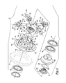
- FIGS. 3 and 4 are exploded views of the differential assembly.
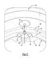
- FIG. 5 is a magnified view of a first case portion of the differential assembly.
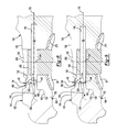
- FIGS. 6-9 are magnified section views of a region of the differential assembly adjacent to a retainer pin.
- the axle assembly 10 may be provided with a motor vehicle like a truck, bus, farm equipment, mining equipment, military transport or weaponry vehicle, or cargo loading equipment for land, air, or marine vessels.
- the motor vehicle may include a trailer for transporting cargo in one or more embodiments.
- the axle assembly 10 may be part of a vehicle drivetrain that may provide torque to one or more traction wheel assemblies that may include a tire mounted on a wheel.
- One or more axle assemblies 10 may be provided with the vehicle.
- the axle assembly 10 may be a single drive axle assembly or may be configured as part of a tandem axle configuration or multi-axle configuration that may include a plurality of axle assemblies that may be connected in series.
- the axle assembly 10 may include a housing assembly 20 , a differential assembly 22 , and at least one axle shaft 24 .
- the housing assembly 20 may receive various components of the axle assembly 10 .
- the housing assembly 20 may facilitate mounting of the axle assembly 10 to the vehicle.
- the housing assembly 20 may include an axle housing 30 and a differential carrier 32 .
- the axle housing 30 may receive and support the axle shafts 24 .
- the axle housing 30 may include a center portion 40 and at least one arm portion 42 .
- the center portion 40 may be disposed proximate the center of the axle housing 30 .
- the center portion 40 may define a cavity that may receive the differential assembly 22 .
- a lower region of the center portion 40 may at least partially define a sump portion that may contain lubricant. Splashed lubricant may flow down the sides of the center portion 40 and may flow over internal components of the axle assembly 10 and gather in the sump portion.
- the center portion 40 may include a carrier mounting surface.
- the carrier mounting surface may face toward and may engage the differential carrier 32 .
- the carrier mounting surface may facilitate mounting of the differential carrier 32 to the axle housing 30 .
- the carrier mounting surface may have a set of holes that may be aligned with corresponding holes on the differential carrier 32 . Each hole may receive a fastener, such as a bolt, that may couple the differential carrier 32 to the axle housing 30 .
- One or more arm portions 42 may extend from the center portion 40 .
- two arm portions 42 may extend in opposite directions from the center portion 40 and away from the differential assembly 22 .
- the arm portions 42 may have substantially similar configurations.
- the arm portions 42 may each have a hollow configuration or tubular configuration that may extend around the corresponding axle shaft 24 and may help separate or isolate the axle shaft 24 from the surrounding environment.
- An arm portion 42 or a portion thereof may be integrally formed with the center portion 40 .
- an arm portion 42 may be separate from the center portion 40 .
- each arm portion 42 may be attached to the center portion 40 in any suitable manner, such as by welding or with one or more fasteners.
- Each arm portion 42 may define an arm cavity that may receive a corresponding axle shaft 24 .
- the differential carrier 32 which may also be called a carrier housing, may be mounted to the center portion 40 of the axle housing 30 .
- the differential carrier 32 may support components of the differential assembly 22 .
- the differential carrier 32 may have a flange portion 50 and one or more bearing supports 52 .
- the flange portion 50 may facilitate mounting of the differential carrier 32 to the axle housing 30 .
- the flange portion 50 may be disposed on the carrier mounting surface of the axle housing 30 and may have a set of holes that may receive fasteners as previously discussed.
- the bearing support 52 may receive a roller bearing assembly 60 that may rotatably support the differential assembly 22 .
- two bearing supports 52 are shown that are configured to be received in the center portion 40 proximate opposite sides of the differential assembly 22 .
- the bearing support 52 may be provided in various configurations.
- a bearing support 52 may include a pair of legs that extend from the differential carrier 32 , such as is shown on the left side of FIG. 2 .
- a bearing cap may be mounted to the legs and may arch over a roller bearing assembly 60 . In such a configuration, the bearing support 52 and bearing cap may cooperate to extend around, receive, and secure the roller bearing assembly 60 .
- the bearing support 52 may be received in a roller bearing assembly 60 which in turn may support the differential assembly 22 .
- the differential assembly 22 may be disposed in the center portion 40 of the housing assembly 20 .
- the differential assembly 22 may transmit torque to the vehicle traction wheel assemblies and permit the traction wheel assemblies to rotate at different velocities.
- An input yoke 70 is shown in FIG. 1 to facilitate an abbreviated discussion of the operation of the axle assembly 10 and the differential assembly 22 .
- the input yoke 70 may be coupled to a vehicle drivetrain component, such as a drive shaft, that may be coupled to an output of a vehicle transmission or transfer case, which in turn may receive torque from a vehicle power source, such as an engine or motor. Alternatively, the input yoke 70 may be operatively connected to an output of another axle assembly.
- the input yoke 70 may be connected to or integrally formed with an input shaft that may be rotatably supported by one or more roller bearings that may be disposed on the differential carrier 32 .
- the input shaft may be operatively connected to a drive pinion 72 , the drive pinion 72 being best shown in FIG. 2 , or may be integrally formed with the drive pinion 72 .
- the drive pinion 72 may provide torque to a ring gear 74 that may be provided with the differential assembly 22 .
- the ring gear 74 may rotate about an axis 76 and may splash lubricant that accumulates in the sump portion as it rotates.
- the ring gear 74 may be operatively connected to the axle shafts 24 .
- the differential assembly 22 may receive torque via the ring gear 74 and provide torque to the axle shafts 24 .
- the differential assembly 22 may include a case 80 , a weld 82 , a first gear 84 , a second gear 86 , a spider 88 , at least one pinion gear 90 , and one or more retainer pins 92 .
- the case 80 may be configured to receive components of the differential assembly 22 .
- the case 80 may be rotatable about the axis 76 .
- the case 80 may include a first case portion 100 and a second case portion 102 that may cooperate to at least partially define a cavity.
- the cavity may at least partially receive the first gear 84 , second gear 86 , spider 88 , and pinion gear(s) 90 .
- the first case portion 100 may include a first bearing portion 110 , a mounting flange 112 , a spider receiving portion 114 , and a first cavity 116 .
- the first bearing portion 110 may extend around the axis 76 and may extend around and may at least partially define a first hole 120 . As is best shown in FIG. 2 , the first bearing portion 110 may be disposed proximate and may engage a roller bearing assembly 60 that may rotatably support the first case portion 100 .
- the mounting flange 112 may be disposed between the first bearing portion 110 and the spider receiving portion 114 .
- the mounting flange 112 may extend from the first bearing portion 110 to the spider receiving portion 114 .
- the mounting flange 112 may extend away from the axis 76 and may extend further away from the axis 76 than the first bearing portion 110 and the spider receiving portion 114 .
- the ring gear 74 may be disposed on the mounting flange 112 and may be oriented such that the teeth of the ring gear 74 extend away from the second case portion 102 .
- the ring gear 74 may be attached to the mounting flange 112 in any suitable manner.
- the ring gear 74 may be welded to the mounting flange 112 or may be attached to the mounting flange 112 with one or more fasteners, such as bolts.
- the spider receiving portion 114 may extend from the mounting flange 112 toward the second case portion 102 . As is best shown in FIG. 3 , the spider receiving portion 114 may extend around and may at least partially define the first cavity 116 . In at least one embodiment, the spider receiving portion 114 may have a first exterior surface 130 , a first weld groove 132 , an intermediate end surface 134 , an inner mounting ring 136 , at least one spider shaft hole 138 , and at least one retainer pin hole 140 .
- the first exterior surface 130 may be an exterior circumferential surface of the spider receiving portion 114 . As such, the first exterior surface 130 may face away from the first cavity 116 . The first exterior surface 130 may extend around the axis 76 and around at least a portion of the first cavity 116 .
- the first weld groove 132 may extend from the first exterior surface 130 .
- the first weld groove 132 may extend from the first exterior surface 130 in a direction that extends toward the second case portion 102 .
- the first weld groove 132 may extend toward the axis 76 and may be disposed closer to the axis 76 than the first exterior surface 130 .
- the first weld groove 132 may extend around at least a portion of the retainer pin hole 140 .
- the first weld groove 132 may be axially positioned or positioned in a direction that extends along the axis 76 between the spider shaft hole 138 and the second case portion 102 .
- the intermediate end surface 134 may extend from an end of the first weld groove 132 toward the axis 76 . In addition, the intermediate end surface 134 may extend to the inner mounting ring 136 . The intermediate end surface 134 may be disposed substantially perpendicular to the axis 76 and one or more embodiments. As is best shown in FIG. 5 , the intermediate end surface 134 may extend to and may intersect one or more of the retainer pin holes 140 .
- the inner mounting ring 136 may be disposed at an end of the first case portion 100 . As is best shown in FIG. 2 , the inner mounting ring 136 may be disposed inside the second case portion 102 . In at least one embodiment, such as is shown in FIGS. 4 and 5 , the inner mounting ring 136 may have an outer surface 150 , an inner mounting ring end surface 152 , and one or more recesses 154 .
- the outer surface 150 may face away from the axis 76 and may face toward an outer mounting ring of the second case portion 102 .
- the outer surface 150 may be a circumferential surface that may extend around the axis 76 and around at least a portion of the first cavity 116 . As such, at least a portion of the outer surface 150 may extend substantially parallel to the axis 76 .
- the outer surface 150 may extend between the intermediate end surface 134 and the inner mounting ring end surface 152 .
- the outer surface 150 may intersect one or more retainer pin holes 140 .
- the inner mounting ring end surface 152 may be disposed at an end of the first case portion 100 that may be disposed opposite the first bearing portion 110 .
- the inner mounting ring end surface 152 may be disposed at an end of the inner mounting ring 136 and may face toward the second case portion 102 .
- the inner mounting ring end surface 152 may be disposed inside the second case portion 102 and may be spaced apart from and may not engage the second case portion 102 .
- the inner mounting ring end surface 152 may extend around the axis 76 and may extend from the first cavity 116 to the outer surface 150 .
- the inner mounting ring end surface 152 may be disposed substantially perpendicular to the axis 76 and may extend from the outer surface 150 toward the axis 76 .
- one or more recesses 154 may be provided with the inner mounting ring 136 .
- two recesses 154 are shown; however, it is contemplated that a greater or lesser number of recesses 154 may be provided.
- Each recess 154 may be disposed adjacent to a corresponding retainer pin hole 140 and may extend at least partially around the retainer pin hole 140 .
- Each recess 154 may be at least partially defined by recess bottom surface 160 and a recess step surface 162 .
- the recess bottom surface 160 may intersect at an end of a corresponding retainer pin hole 140 .
- the recess bottom surface 160 may be axially positioned between the intermediate end surface 134 and the inner mounting ring end surface 152 .
- the recess bottom surface 160 may extend from the outer surface 150 and from the retainer pin hole 140 toward the axis 76 and to the recess step surface 162 .
- the recess step surface 162 may be spaced apart from the retainer pin hole 140 .
- the recess step surface 162 may extend axially from the inner mounting ring end surface 152 to the recess bottom surface 160 .
- opposite ends of the recess step surface 162 may intersect the outer surface 150 and the recess step surface 162 may extend along an arc or curve.
- the recess step surface 162 may extend along an arc or curve that may extend away from the outer surface 150 and toward the axis 76 .
- the recess step surface 162 may be spaced apart from and may not engage the second case portion 102 .
- spider shaft holes 138 may be provided in the spider receiving portion 114 .
- a spider shaft hole 138 may receive a shaft of the spider 88 as will be discussed in more detail below.
- four spider shaft holes 138 are shown; however, it is contemplated that a greater or lesser number of spider shaft holes 138 may be provided.
- the spider shaft holes 138 may be spaced apart from each other and may be arranged around the axis 76 .
- spider shaft holes 138 may be disposed along axes that may be disposed substantially perpendicular to the axis 76 .
- the spider shaft holes 138 may be through holes that may be completely defined in the first case portion 100 .
- spider shaft holes 138 may extend from the first cavity 116 to the first exterior surface 130 .
- the spider shaft holes 138 may be axially positioned between the mounting flange 112 and the first weld groove 132 .
- One or more retainer pin holes 140 may be provided with the first case portion 100 .
- a retainer pin hole 140 may receive a retainer pin 92 that may couple or secure the spider 88 to the first case portion 100 as will be discussed in more detail below.
- FIG. 4 two retainer pin holes 140 are shown that are disposed directly opposite each other; however, it is contemplated that a greater or lesser number of retainer pin holes 140 may be provided and that each retainer pin hole 140 need not be disposed directly opposite another retainer pin hole 140 .
- a retainer pin hole 140 may extend through the inner mounting ring 136 to a spider shaft hole 138 . More specifically, a retainer pin hole 140 may extend from the recess bottom surface 160 to at least the spider shaft hole 138 as is best shown in FIG. 6 .
- a portion of the retainer pin hole 140 may extend in an axial direction from the spider shaft hole 138 toward the first bearing portion 110 and the mounting flange 112 , thereby permitting the retainer pin 92 to be inserted completely through a shaft of the spider 88 as will be discussed in more detail below.
- each retainer pin hole 140 may extend along a corresponding retainer pin hole axis 170 .
- the retainer pin hole axis 170 may be disposed substantially parallel to the axis 76 and may intersect the second case portion 102 .
- the retainer pin hole axis 170 may be disposed closer to the axis 76 than the outer surface 150 or where the outer surface 150 intersects the retainer pin hole 140 .
- the second case portion 102 may be mounted on the first case portion 100 .
- the second case portion 102 may be fixedly disposed on the spider receiving portion 114 of the first case portion 100 such that the second case portion 102 does not rotate with respect to the first case portion 100 .
- the second case portion 102 may be assembled to the first case portion 100 with the weld 82 , which is best shown in FIG. 6 , or alternatively with one or more fasteners that may extend through holes in the second case portion 102 .
- the second case portion 102 may include a second bearing portion 180 , a second mounting portion 182 , and a second cavity 184 .
- the second bearing portion 180 may extend around the axis 76 and may extend around the second cavity 184 .
- a roller bearing assembly 60 that rotatably supports the second case portion 102 may be disposed on the second bearing portion 180 .
- the second mounting portion 182 may extend from the second bearing portion 180 toward the first case portion 100 .
- the second mounting portion 182 may also extend outwardly from the second bearing portion 180 and away from the axis 76 .
- the second case portion 102 and the second mounting portion 182 may extend away from the axis 76 by a sufficient distance to cover the retainer pin holes 140 .
- the second mounting portion 182 may extend around and may at least partially define the second cavity 184 .
- the second mounting portion 182 may include a second exterior surface 190 , a second weld groove 192 , and an outer mounting ring 194 .
- the second exterior surface 190 may be an exterior circumferential surface of the second mounting portion 182 . As such, the second exterior surface 190 may face away from the second cavity 184 . The second exterior surface 190 may extend around the axis 76 and around at least a portion of the second cavity 184 .
- the second weld groove 192 may extend from the second exterior surface 190 .
- the second weld groove 192 may extend from the second exterior surface 190 in a direction that extends toward the first case portion 100 and to the first weld groove 132 .
- the second weld groove 192 may extend toward the axis 76 and may be disposed closer to the axis 76 than the second exterior surface 190 .
- the second weld groove 192 may extend around at least a portion of the retainer pin hole 140 .
- the second weld groove 192 may be provided on or may at least partially define the outer mounting ring 194 .
- the first weld groove 132 and the second weld groove 192 may be axially positioned between the spider shaft hole 138 and the inner mounting ring end surface 152 .
- the outer mounting ring 194 may extend around the inner mounting ring 136 .
- the outer mounting ring 194 may extend around and may engage the outer surface 150 of the inner mounting ring 136 .
- the outer mounting ring 194 may have an outer mounting ring end surface 200 .
- the outer mounting ring end surface 200 may be disposed at an end of the second case portion 102 that may be disposed opposite the second bearing portion 180 .
- the outer mounting ring end surface 200 may be disposed at an end of the outer mounting ring 194 and may face toward and may engage the intermediate end surface 134 of the first case portion 100 .
- the outer mounting ring end surface 200 may extend around the axis 76 .
- the outer mounting ring end surface 200 may be disposed substantially perpendicular to the axis 76 in one or more embodiments.
- the outer mounting ring end surface 200 may extend from the second cavity 184 to the second weld groove 192 . As is best shown in FIG.
- the outer mounting ring end surface 200 may partially overlap a retainer pin hole 140 or may be partially received in a retainer pin hole 140 to inhibit removal of the retainer pin 92 from the retainer pin hole 140 . As such, the outer mounting ring end surface 200 may engage an end of a retainer pin 92 to limit or inhibit axial movement of the retainer pin 92 .
- the second cavity 184 may be disposed inside the second case portion 102 .
- the second cavity 184 may at least partially receive the second gear 86 and an axle shaft 24 .
- the second cavity 184 may extend from an end of the second mounting portion 182 through the second case portion 102 .
- the weld 82 may join the first case portion 100 to the second case portion 102 .
- the weld 82 may be provided in the first weld groove 132 and the second weld groove 192 and may extend continuously around the axis 76 .
- the weld 82 may extend to the retainer pin hole 140 but may not extend to the retainer pin 92 .
- the retainer pin hole 140 may have a length that is greater than the length of a retainer pin 92 to allow the retainer pin 92 to be inserted to a sufficient depth that is clear of or spaced apart from the weld 82 . As shown in FIG.
- the weld 82 may alternatively extend to the retainer pin 92 and may join the retainer pin 92 to the case 80 , thereby inhibiting movement of the retainer pin 92 .
- the retainer pin hole 140 is shown with a shorter axial length than in FIGS. 6-8 , which may help position the retainer pin 92 closer to the outer mounting ring end surface 200 and the weld 82 .
- the first gear 84 may be disposed in the first case portion 100 .
- the first gear 84 may be at least partially disposed in the first hole 120 and may be configured to rotate about the axis 76 .
- the first gear 84 may include a first gear hole 210 and a gear portion 212 .
- the first gear hole 210 may be disposed along the axis 76 .
- the first gear hole 210 may be configured to receive the first axle shaft 24 .
- the first gear 84 may rotate with the first axle shaft 24 .
- the first gear hole 210 may have a spline that may mate with a corresponding spline on the first axle shaft 24 such that the first gear 84 may not rotate with respect to the first axle shaft 24 .
- the gear portion 212 may face toward and may be spaced apart from the spider 88 .
- the gear portion 212 may have a set of teeth that may be arranged around the axis 76 and that may mate with teeth on one or more pinion gears 90 .
- a thrust washer 220 or bearing may be disposed between the gear portion 212 and the first case portion 100 .
- the second gear 86 may be disposed in the first case portion 100 and the second case portion 102 .
- the second gear 86 may be at least partially disposed in the second cavity 184 and the second cavity 184 and may be configured to rotate about the axis 76 .
- the second gear 86 may be spaced apart from the first gear 84 and may have a similar or identical configuration as the first gear 84 .
- the second gear 86 may include a second gear hole 230 and a gear portion 232 .
- the second gear hole 230 may be disposed along the axis 76 .
- the second gear hole 230 may be configured to receive the second axle shaft 24 .
- the second gear 86 may rotate with the second axle shaft 24 .
- the second gear hole 230 may have a spline that may mate with a corresponding spline on the second axle shaft 24 such that the second gear 86 may not rotate with respect to the second axle shaft 24 .
- the gear portion 232 may face toward and may be spaced apart from the spider 88 .
- the gear portion 232 may have a set of teeth that may be arranged around the axis 76 and that may mate with teeth on one or more pinion gears 90 .
- a thrust washer 220 or bearing may be disposed between the gear portion 232 and the second case portion 102 .
- the spider 88 may rotate about the axis 76 with the case 80 .
- the spider 88 may include a primary spider shaft 240 and at least one secondary spider shaft 242 .
- the primary spider shaft 240 may be mounted to the first case portion 100 .
- the primary spider shaft 240 may have opposing ends that may be received in corresponding spider shaft holes 138 of the first case portion 100 .
- the primary spider shaft 240 may extend across the first cavity 116 and may extend through the axis 76 .
- the primary spider shaft 240 may be spaced apart from and may not engage the second case portion 102 .
- the primary spider shaft 240 may be disposed along a primary spider shaft axis 250 .
- the primary spider shaft axis 250 may intersect and may be disposed substantially perpendicular to the axis 76 .
- the primary spider shaft 240 may have a generally cylindrical configuration and may include one or more notches 252 .
- One or more notches 252 may be disposed proximate the center of the primary spider shaft 240 . In the configuration shown, two notches 252 are provided that are disposed opposite each other and extend inwardly toward the axis 76 . A notch 252 may receive and facilitate positioning of a secondary spider shaft 242 with respect to the primary spider shaft 240 .
- one or more secondary spider shafts 242 may be mounted to the first case portion 100 .
- the secondary spider shaft 242 may extend from a spider shaft hole 138 to the primary spider shaft 240 .
- the secondary spider shaft 242 may have a first end that may be received in the notch 252 of the primary spider shaft 240 and a second end that may be disposed opposite the first end and may be received in a corresponding spider shaft hole 138 .
- the secondary spider shaft 242 may be spaced apart from and may not engage the second case portion 102 .
- the secondary spider shaft 242 may be disposed along a secondary spider shaft axis 260 .
- the secondary spider shaft axis 260 may intersect and may be disposed substantially perpendicular to the axis 76 and the primary spider shaft axis 250 .
- the primary spider shaft axis 250 and secondary spider shaft axis 260 may be substantially coplanar or disposed in a common plane.
- two secondary spider shafts 242 are provided that are disposed on opposite sides of the primary spider shaft 240 and are coaxially disposed along the secondary spider shaft axis 260 .
- the secondary spider shafts 242 may have common or substantially identical configurations that may include a tapered end 262 and a retainer pin receiving hole 264 .
- the tapered end 262 may be disposed proximate the primary spider shaft 240 .
- the tapered end 262 may be received in a notch 252 of the primary spider shaft 240 .
- the secondary spider shaft 242 and its tapered end 262 may not be fixedly attached to the primary spider shaft 240 in one or more embodiments.
- the secondary spider shaft 242 may have a retainer pin receiving hole 264 that may receive the retainer pin 92 .
- the retainer pin receiving hole 264 may be disposed near the second end of the secondary spider shaft 242 and may be aligned with a corresponding retainer pin hole 140 in the first case portion 100 . It is also contemplated that one or more retainer pin receiving holes 264 may be provided with the primary spider shaft 240 in one or more embodiments.
- a pinion gear 90 may be rotatably disposed on the primary spider shaft 240 and the secondary spider shafts 242 .
- two pinion gears 90 may be disposed on the primary spider shaft 240 while a single pinion gear 90 may be disposed on each secondary spider shaft 242 .
- Each pinion gear 90 may be disposed in the cavity of the case 80 and may be rotatably supported or retained on a corresponding spider shaft with one or more fasteners 270 , such as a washer and/or a thrust bearing.
- the fastener 270 may engage an inner wall of the first case portion 100 .
- the pinion gears 90 on the primary spider shaft 240 may rotate about the primary spider shaft axis 250 .
- the pinion gear 90 on the secondary spider shaft 242 may rotate about the secondary spider shaft axis 260 .
- Each pinion gear 90 may include a set of teeth that mate with teeth on the first gear 84 and teeth on the second gear 86 .
- one or more retainer pins 92 may be provided to secure or couple the primary spider shaft 240 and/or the secondary spider shaft 242 to the first case portion 100 .
- a retainer pin 92 may be received in a retainer pin hole 140 and may extend through a corresponding retainer pin receiving hole 264 in a spider shaft, such as a secondary spider shaft 242 .
- the retainer pin 92 may couple a spider shaft to the first case portion 100 to inhibit radial movement of a spider shaft or movement of the spider shaft toward or away from the axis 76 .
- the retainer pin 92 may provide a double shear joint by inserting the retainer pin 92 completely through the retainer pin hole 140 such that the retainer pin 92 extends into portions of the retainer pin hole 140 that are located on opposite sides of the spider shaft.
- the retainer pin 92 may have any suitable configuration.
- the retainer pin 92 may be configured as a hollow or solid cylindrical rod or as a roll pin or spiral pin.
- the retainer pin 92 may be received in the retainer pin hole 140 and the retainer pin receiving hole 264 in various ways.
- the retainer pin 92 is received in the retainer pin hole 140 and the retainer pin receiving hole 264 with a clearance fit. As such, the retainer pin 92 may be free to move axially or along the retainer pin hole axis 170 . In FIG. 6 , the retainer pin 92 is fully inserted in the retainer pin hole 140 and is spaced apart from the second case portion 102 and the outer mounting ring end surface 200 of the outer mounting ring 194 .
- the retainer pin 92 is moved to the left as compared to FIG. 6 .
- an end of the retainer pin 92 engages the outer mounting ring end surface 200 of the second case portion 102 , which is shown overlapping or extending into the retainer pin hole 140 .
- the outer mounting ring 194 inhibits or limits axial movement of the retainer pin 92 and prevents the retainer pin 92 from exiting the retainer pin hole 140 , which in turn helps retain a corresponding spider shaft to the case 80 .
- the retainer pin 92 is received in the retainer pin hole 140 and the retainer pin receiving hole 264 with an interference fit.
- An interference fit may further aid in inhibiting axial movement of the retainer pin 92 . It is contemplated that an interference fit may be provided between the retainer pin 92 and the retainer pin hole 140 or a portion thereof, between the retainer pin 92 and the retainer pin receiving hole 264 , or combinations thereof.
- the configuration shown in FIG. 9 with a shorter retainer pin hole 140 may be provided with an interference fit or a clearance fit.
- the axle shafts 24 may transmit torque from the differential assembly 22 to corresponding traction wheel assemblies.
- two axle shafts 24 are provided such that each axle shaft 24 extends through a different arm portion 42 of axle housing 30 .
- the axle shafts 24 may extend along and may be rotated about the axis 76 by the differential assembly 22 .
- Each axle shaft 24 may have a first end and a second end. The first end may be coupled to the differential assembly 22 . The second end may be disposed opposite the first end and may be operatively connected to a wheel end assembly that may have a wheel hub that may support a wheel.
- an axle flange 280 may be disposed proximate the second end of the axle shaft 24 and may facilitate coupling of the axle shaft 24 to the wheel hub.
Landscapes
- Engineering & Computer Science (AREA)
- General Engineering & Computer Science (AREA)
- Mechanical Engineering (AREA)
- Retarders (AREA)
Abstract
Description
- This disclosure relates to an axle assembly that may include a differential assembly having a case that is configured to retain shafts of the spider.
- A differential assembly having a case that is configured to retain shafts of a spider is disclosed in U.S. patent application Ser. No. 14/996,663.
- In at least one embodiment, a differential assembly is provided. The differential assembly may include a case, a spider, and a retainer pin. The case may be rotatable about an axis and may include a first case portion and a second case portion. The first case portion may have a spider receiving portion, an inner mounting ring, and a retainer pin hole. The spider receiving portion may have a spider shaft hole. The inner mounting ring may be disposed at an end of the first case portion. The retainer pin hole may extend through the inner mounting ring to the spider shaft hole. The second case portion may be disposed on the spider receiving portion. The second case portion may have an outer mounting ring that may extend around the inner mounting ring. The spider may have a secondary spider shaft that may be received in the spider shaft hole. The retainer pin may be disposed in the retainer pin hole and may couple the secondary spider shaft to the first case portion. The outer mounting ring may partially overlap the retainer pin hole to inhibit removal of the retainer pin from the retainer pin hole.
- In at least one embodiment, a differential assembly is provided. The differential assembly may include a case, a spider, a retainer pin, and a weld. The case may have a first case portion and a second case portion. The first case portion may have a retainer pin hole and a first weld groove. The retainer pin hole may extend from a spider shaft hole to an inner mounting ring that may be disposed at an end of the first case portion. The first weld groove may extend around at least a portion of the retainer pin hole. The second case portion may have an outer mounting ring and a second weld groove. The outer mounting ring may extend around the inner mounting ring. The second weld groove may extend around at least a portion of the retainer pin hole. The spider may have a primary spider shaft and a secondary spider shaft. The primary spider shaft may be mounted to the first case portion. The secondary spider shaft may be received in the spider shaft hole and may extend from the spider shaft hole to the primary spider shaft. The retainer pin may be disposed in the retainer pin hole. The retainer pin may couple the secondary spider shaft to the first case portion. The outer mounting ring may inhibit removal of the retainer pin from the retainer pin hole. The weld may be provided in the first weld groove and the second weld groove to join the first case portion to the second case portion.
- In at least one embodiment, an axle assembly is provided. The axle assembly may include a differential assembly that has a case, a spider, and a retainer pin. The case may be rotatable about an axis and may include a first case portion and a second case portion. The first case portion may have a first cavity, an exterior surface, a spider shaft hole, an inner mounting ring, and a retainer pin hole. The exterior surface may extend around the first cavity. The spider shaft hole may extend from the exterior surface to the first cavity. The retainer pin hole may extend from the inner mounting ring to the spider shaft hole. The second case portion may be mounted to the first case portion and may include an outer mounting ring. The outer mounting ring may extend around the inner mounting ring and may be partially received in the retainer pin hole. The spider may include a primary spider shaft and a secondary spider shaft. The primary spider shaft may be mounted to the first case portion. The secondary spider shaft may be received in the spider shaft hole and may extend between the spider shaft hole and the primary spider shaft. The primary and secondary spider shafts may not engage the second case portion. The retainer pin may couple the secondary spider shaft to the first case portion. The outer mounting ring may inhibit axial movement of the retainer pin.
-
FIG. 1 is a perspective view of an axle assembly having a differential carrier that supports a differential assembly. -
FIG. 2 is a section view of a portion of the differential carrier along section line 2-2. -
FIGS. 3 and 4 are exploded views of the differential assembly. -
FIG. 5 is a magnified view of a first case portion of the differential assembly. -
FIGS. 6-9 are magnified section views of a region of the differential assembly adjacent to a retainer pin. - As required, detailed embodiments of the present invention are disclosed herein; however, it is to be understood that the disclosed embodiments are merely exemplary of the invention that may be embodied in various and alternative forms. The figures are not necessarily to scale; some features may be exaggerated or minimized to show details of particular components. Therefore, specific structural and functional details disclosed herein are not to be interpreted as limiting, but merely as a representative basis for teaching one skilled in the art to variously employ the present invention.
- Referring to
FIG. 1 , an example of anaxle assembly 10 is shown. Theaxle assembly 10 may be provided with a motor vehicle like a truck, bus, farm equipment, mining equipment, military transport or weaponry vehicle, or cargo loading equipment for land, air, or marine vessels. The motor vehicle may include a trailer for transporting cargo in one or more embodiments. - The
axle assembly 10 may be part of a vehicle drivetrain that may provide torque to one or more traction wheel assemblies that may include a tire mounted on a wheel. One ormore axle assemblies 10 may be provided with the vehicle. For example, theaxle assembly 10 may be a single drive axle assembly or may be configured as part of a tandem axle configuration or multi-axle configuration that may include a plurality of axle assemblies that may be connected in series. As is best shown with reference toFIGS. 1 and 2 , theaxle assembly 10 may include ahousing assembly 20, adifferential assembly 22, and at least oneaxle shaft 24. - Referring to
FIG. 1 , thehousing assembly 20 may receive various components of theaxle assembly 10. In addition, thehousing assembly 20 may facilitate mounting of theaxle assembly 10 to the vehicle. Thehousing assembly 20 may include anaxle housing 30 and adifferential carrier 32. - The
axle housing 30 may receive and support theaxle shafts 24. In at least one embodiment, theaxle housing 30 may include acenter portion 40 and at least onearm portion 42. - The
center portion 40 may be disposed proximate the center of theaxle housing 30. Thecenter portion 40 may define a cavity that may receive thedifferential assembly 22. A lower region of thecenter portion 40 may at least partially define a sump portion that may contain lubricant. Splashed lubricant may flow down the sides of thecenter portion 40 and may flow over internal components of theaxle assembly 10 and gather in the sump portion. - The
center portion 40 may include a carrier mounting surface. The carrier mounting surface may face toward and may engage thedifferential carrier 32. The carrier mounting surface may facilitate mounting of thedifferential carrier 32 to theaxle housing 30. For example, the carrier mounting surface may have a set of holes that may be aligned with corresponding holes on thedifferential carrier 32. Each hole may receive a fastener, such as a bolt, that may couple thedifferential carrier 32 to theaxle housing 30. - One or
more arm portions 42 may extend from thecenter portion 40. For example, twoarm portions 42 may extend in opposite directions from thecenter portion 40 and away from thedifferential assembly 22. Thearm portions 42 may have substantially similar configurations. For example, thearm portions 42 may each have a hollow configuration or tubular configuration that may extend around the correspondingaxle shaft 24 and may help separate or isolate theaxle shaft 24 from the surrounding environment. Anarm portion 42 or a portion thereof may be integrally formed with thecenter portion 40. Alternatively, anarm portion 42 may be separate from thecenter portion 40. In such a configuration, eacharm portion 42 may be attached to thecenter portion 40 in any suitable manner, such as by welding or with one or more fasteners. Eacharm portion 42 may define an arm cavity that may receive acorresponding axle shaft 24. - Referring to
FIGS. 1 and 2 , thedifferential carrier 32, which may also be called a carrier housing, may be mounted to thecenter portion 40 of theaxle housing 30. Thedifferential carrier 32 may support components of thedifferential assembly 22. As is best shown inFIG. 2 , thedifferential carrier 32 may have aflange portion 50 and one or more bearing supports 52. - Referring to
FIGS. 1 and 2 , theflange portion 50 may facilitate mounting of thedifferential carrier 32 to theaxle housing 30. For example, theflange portion 50 may be disposed on the carrier mounting surface of theaxle housing 30 and may have a set of holes that may receive fasteners as previously discussed. - Referring to
FIG. 2 , the bearingsupport 52 may receive aroller bearing assembly 60 that may rotatably support thedifferential assembly 22. InFIG. 2 , two bearing supports 52 are shown that are configured to be received in thecenter portion 40 proximate opposite sides of thedifferential assembly 22. The bearingsupport 52 may be provided in various configurations. For example, a bearingsupport 52 may include a pair of legs that extend from thedifferential carrier 32, such as is shown on the left side ofFIG. 2 . A bearing cap may be mounted to the legs and may arch over aroller bearing assembly 60. In such a configuration, the bearingsupport 52 and bearing cap may cooperate to extend around, receive, and secure theroller bearing assembly 60. As another example such as is shown on the right side ofFIG. 2 , the bearingsupport 52 may be received in aroller bearing assembly 60 which in turn may support thedifferential assembly 22. - Referring to
FIG. 2 , thedifferential assembly 22 may be disposed in thecenter portion 40 of thehousing assembly 20. Thedifferential assembly 22 may transmit torque to the vehicle traction wheel assemblies and permit the traction wheel assemblies to rotate at different velocities. Aninput yoke 70 is shown inFIG. 1 to facilitate an abbreviated discussion of the operation of theaxle assembly 10 and thedifferential assembly 22. - The
input yoke 70 may be coupled to a vehicle drivetrain component, such as a drive shaft, that may be coupled to an output of a vehicle transmission or transfer case, which in turn may receive torque from a vehicle power source, such as an engine or motor. Alternatively, theinput yoke 70 may be operatively connected to an output of another axle assembly. Theinput yoke 70 may be connected to or integrally formed with an input shaft that may be rotatably supported by one or more roller bearings that may be disposed on thedifferential carrier 32. The input shaft may be operatively connected to adrive pinion 72, thedrive pinion 72 being best shown inFIG. 2 , or may be integrally formed with thedrive pinion 72. Thedrive pinion 72 may provide torque to aring gear 74 that may be provided with thedifferential assembly 22. Thering gear 74 may rotate about anaxis 76 and may splash lubricant that accumulates in the sump portion as it rotates. Thering gear 74 may be operatively connected to theaxle shafts 24. As such, thedifferential assembly 22 may receive torque via thering gear 74 and provide torque to theaxle shafts 24. - Referring to
FIGS. 2-4 , an example of adifferential assembly 22 is shown in more detail. In addition to thering gear 74, thedifferential assembly 22 may include acase 80, aweld 82, afirst gear 84, asecond gear 86, aspider 88, at least onepinion gear 90, and one or more retainer pins 92. - The
case 80 may be configured to receive components of thedifferential assembly 22. In addition, thecase 80 may be rotatable about theaxis 76. In at least one embodiment, thecase 80 may include afirst case portion 100 and asecond case portion 102 that may cooperate to at least partially define a cavity. The cavity may at least partially receive thefirst gear 84,second gear 86,spider 88, and pinion gear(s) 90. - Referring to
FIGS. 2-5 , an example of afirst case portion 100 is shown. As is best shown beginning withFIGS. 2-4 , thefirst case portion 100 may include afirst bearing portion 110, a mountingflange 112, aspider receiving portion 114, and afirst cavity 116. - Referring to
FIGS. 2 and 3 , thefirst bearing portion 110 may extend around theaxis 76 and may extend around and may at least partially define afirst hole 120. As is best shown inFIG. 2 , thefirst bearing portion 110 may be disposed proximate and may engage aroller bearing assembly 60 that may rotatably support thefirst case portion 100. - Referring to
FIGS. 2 and 4 , the mountingflange 112 may be disposed between thefirst bearing portion 110 and thespider receiving portion 114. For example, the mountingflange 112 may extend from thefirst bearing portion 110 to thespider receiving portion 114. The mountingflange 112 may extend away from theaxis 76 and may extend further away from theaxis 76 than thefirst bearing portion 110 and thespider receiving portion 114. Thering gear 74 may be disposed on the mountingflange 112 and may be oriented such that the teeth of thering gear 74 extend away from thesecond case portion 102. Thering gear 74 may be attached to the mountingflange 112 in any suitable manner. For instance, thering gear 74 may be welded to the mountingflange 112 or may be attached to the mountingflange 112 with one or more fasteners, such as bolts. - Referring to
FIGS. 2 and 3 , thespider receiving portion 114 may extend from the mountingflange 112 toward thesecond case portion 102. As is best shown inFIG. 3 , thespider receiving portion 114 may extend around and may at least partially define thefirst cavity 116. In at least one embodiment, thespider receiving portion 114 may have a firstexterior surface 130, afirst weld groove 132, anintermediate end surface 134, aninner mounting ring 136, at least onespider shaft hole 138, and at least oneretainer pin hole 140. - Referring to
FIGS. 4 and 5 , the firstexterior surface 130 may be an exterior circumferential surface of thespider receiving portion 114. As such, the firstexterior surface 130 may face away from thefirst cavity 116. The firstexterior surface 130 may extend around theaxis 76 and around at least a portion of thefirst cavity 116. - The
first weld groove 132 may extend from the firstexterior surface 130. For example, thefirst weld groove 132 may extend from the firstexterior surface 130 in a direction that extends toward thesecond case portion 102. In addition, thefirst weld groove 132 may extend toward theaxis 76 and may be disposed closer to theaxis 76 than the firstexterior surface 130. As is best shown inFIG. 6 , thefirst weld groove 132 may extend around at least a portion of theretainer pin hole 140. Thefirst weld groove 132 may be axially positioned or positioned in a direction that extends along theaxis 76 between thespider shaft hole 138 and thesecond case portion 102. - The
intermediate end surface 134 may extend from an end of thefirst weld groove 132 toward theaxis 76. In addition, theintermediate end surface 134 may extend to theinner mounting ring 136. Theintermediate end surface 134 may be disposed substantially perpendicular to theaxis 76 and one or more embodiments. As is best shown inFIG. 5 , theintermediate end surface 134 may extend to and may intersect one or more of the retainer pin holes 140. - Referring to
FIGS. 4 and 5 , theinner mounting ring 136 may be disposed at an end of thefirst case portion 100. As is best shown inFIG. 2 , theinner mounting ring 136 may be disposed inside thesecond case portion 102. In at least one embodiment, such as is shown inFIGS. 4 and 5 , theinner mounting ring 136 may have anouter surface 150, an inner mountingring end surface 152, and one or more recesses 154. - The
outer surface 150 may face away from theaxis 76 and may face toward an outer mounting ring of thesecond case portion 102. Theouter surface 150 may be a circumferential surface that may extend around theaxis 76 and around at least a portion of thefirst cavity 116. As such, at least a portion of theouter surface 150 may extend substantially parallel to theaxis 76. Theouter surface 150 may extend between theintermediate end surface 134 and the inner mountingring end surface 152. In addition, theouter surface 150 may intersect one or more retainer pin holes 140. - Referring to
FIGS. 2 and 5 , the inner mountingring end surface 152 may be disposed at an end of thefirst case portion 100 that may be disposed opposite thefirst bearing portion 110. For example, the inner mountingring end surface 152 may be disposed at an end of theinner mounting ring 136 and may face toward thesecond case portion 102. As is best shown inFIG. 6 , the inner mountingring end surface 152 may be disposed inside thesecond case portion 102 and may be spaced apart from and may not engage thesecond case portion 102. The inner mountingring end surface 152 may extend around theaxis 76 and may extend from thefirst cavity 116 to theouter surface 150. As such, the inner mountingring end surface 152 may be disposed substantially perpendicular to theaxis 76 and may extend from theouter surface 150 toward theaxis 76. - Referring to
FIGS. 4 and 5 , one ormore recesses 154 may be provided with theinner mounting ring 136. InFIG. 4 , tworecesses 154 are shown; however, it is contemplated that a greater or lesser number ofrecesses 154 may be provided. Eachrecess 154 may be disposed adjacent to a correspondingretainer pin hole 140 and may extend at least partially around theretainer pin hole 140. Eachrecess 154 may be at least partially defined byrecess bottom surface 160 and arecess step surface 162. - The
recess bottom surface 160 may intersect at an end of a correspondingretainer pin hole 140. Therecess bottom surface 160 may be axially positioned between theintermediate end surface 134 and the inner mountingring end surface 152. In addition, therecess bottom surface 160 may extend from theouter surface 150 and from theretainer pin hole 140 toward theaxis 76 and to therecess step surface 162. - The
recess step surface 162 may be spaced apart from theretainer pin hole 140. Therecess step surface 162 may extend axially from the inner mountingring end surface 152 to therecess bottom surface 160. As is best shown inFIG. 5 , opposite ends of therecess step surface 162 may intersect theouter surface 150 and therecess step surface 162 may extend along an arc or curve. For example, therecess step surface 162 may extend along an arc or curve that may extend away from theouter surface 150 and toward theaxis 76. As such, therecess step surface 162 may be spaced apart from and may not engage thesecond case portion 102. - Referring to
FIG. 4 , one or more spider shaft holes 138 may be provided in thespider receiving portion 114. Aspider shaft hole 138 may receive a shaft of thespider 88 as will be discussed in more detail below. InFIG. 4 , four spider shaft holes 138 are shown; however, it is contemplated that a greater or lesser number of spider shaft holes 138 may be provided. The spider shaft holes 138 may be spaced apart from each other and may be arranged around theaxis 76. For example, spider shaft holes 138 may be disposed along axes that may be disposed substantially perpendicular to theaxis 76. The spider shaft holes 138 may be through holes that may be completely defined in thefirst case portion 100. For example, spider shaft holes 138 may extend from thefirst cavity 116 to the firstexterior surface 130. In addition, the spider shaft holes 138 may be axially positioned between the mountingflange 112 and thefirst weld groove 132. - One or more retainer pin holes 140 may be provided with the
first case portion 100. Aretainer pin hole 140 may receive aretainer pin 92 that may couple or secure thespider 88 to thefirst case portion 100 as will be discussed in more detail below. InFIG. 4 , two retainer pin holes 140 are shown that are disposed directly opposite each other; however, it is contemplated that a greater or lesser number of retainer pin holes 140 may be provided and that eachretainer pin hole 140 need not be disposed directly opposite anotherretainer pin hole 140. Aretainer pin hole 140 may extend through theinner mounting ring 136 to aspider shaft hole 138. More specifically, aretainer pin hole 140 may extend from therecess bottom surface 160 to at least thespider shaft hole 138 as is best shown inFIG. 6 . In addition, a portion of theretainer pin hole 140 may extend in an axial direction from thespider shaft hole 138 toward thefirst bearing portion 110 and the mountingflange 112, thereby permitting theretainer pin 92 to be inserted completely through a shaft of thespider 88 as will be discussed in more detail below. - Referring to
FIG. 6 , eachretainer pin hole 140 may extend along a corresponding retainerpin hole axis 170. The retainerpin hole axis 170 may be disposed substantially parallel to theaxis 76 and may intersect thesecond case portion 102. In addition, the retainerpin hole axis 170 may be disposed closer to theaxis 76 than theouter surface 150 or where theouter surface 150 intersects theretainer pin hole 140. - Referring to
FIGS. 2-4 , thesecond case portion 102 may be mounted on thefirst case portion 100. Thesecond case portion 102 may be fixedly disposed on thespider receiving portion 114 of thefirst case portion 100 such that thesecond case portion 102 does not rotate with respect to thefirst case portion 100. For instance, thesecond case portion 102 may be assembled to thefirst case portion 100 with theweld 82, which is best shown inFIG. 6 , or alternatively with one or more fasteners that may extend through holes in thesecond case portion 102. In at least one embodiment, thesecond case portion 102 may include asecond bearing portion 180, a second mountingportion 182, and asecond cavity 184. - Referring to
FIG. 3 , thesecond bearing portion 180 may extend around theaxis 76 and may extend around thesecond cavity 184. As is best shown inFIG. 2 , aroller bearing assembly 60 that rotatably supports thesecond case portion 102 may be disposed on thesecond bearing portion 180. - The
second mounting portion 182 may extend from thesecond bearing portion 180 toward thefirst case portion 100. Thesecond mounting portion 182 may also extend outwardly from thesecond bearing portion 180 and away from theaxis 76. Moreover, thesecond case portion 102 and the second mountingportion 182 may extend away from theaxis 76 by a sufficient distance to cover the retainer pin holes 140. As is best shown inFIG. 3 , the second mountingportion 182 may extend around and may at least partially define thesecond cavity 184. Thesecond mounting portion 182 may include a secondexterior surface 190, asecond weld groove 192, and anouter mounting ring 194. - Referring to
FIGS. 3 and 6 , the secondexterior surface 190 may be an exterior circumferential surface of the second mountingportion 182. As such, the secondexterior surface 190 may face away from thesecond cavity 184. The secondexterior surface 190 may extend around theaxis 76 and around at least a portion of thesecond cavity 184. - The
second weld groove 192 may extend from the secondexterior surface 190. For example, thesecond weld groove 192 may extend from the secondexterior surface 190 in a direction that extends toward thefirst case portion 100 and to thefirst weld groove 132. In addition, thesecond weld groove 192 may extend toward theaxis 76 and may be disposed closer to theaxis 76 than the secondexterior surface 190. As is best shown inFIG. 6 , thesecond weld groove 192 may extend around at least a portion of theretainer pin hole 140. Thesecond weld groove 192 may be provided on or may at least partially define theouter mounting ring 194. Moreover, thefirst weld groove 132 and thesecond weld groove 192 may be axially positioned between thespider shaft hole 138 and the inner mountingring end surface 152. - The
outer mounting ring 194 may extend around theinner mounting ring 136. For example, theouter mounting ring 194 may extend around and may engage theouter surface 150 of theinner mounting ring 136. In at least one embodiment, theouter mounting ring 194 may have an outer mountingring end surface 200. - Referring to
FIGS. 3 and 6 , the outer mountingring end surface 200 may be disposed at an end of thesecond case portion 102 that may be disposed opposite thesecond bearing portion 180. For example, the outer mountingring end surface 200 may be disposed at an end of theouter mounting ring 194 and may face toward and may engage theintermediate end surface 134 of thefirst case portion 100. The outer mountingring end surface 200 may extend around theaxis 76. For example, the outer mountingring end surface 200 may be disposed substantially perpendicular to theaxis 76 in one or more embodiments. The outer mountingring end surface 200 may extend from thesecond cavity 184 to thesecond weld groove 192. As is best shown inFIG. 6 , the outer mountingring end surface 200 may partially overlap aretainer pin hole 140 or may be partially received in aretainer pin hole 140 to inhibit removal of theretainer pin 92 from theretainer pin hole 140. As such, the outer mountingring end surface 200 may engage an end of aretainer pin 92 to limit or inhibit axial movement of theretainer pin 92. - Referring to
FIG. 2 , thesecond cavity 184 may be disposed inside thesecond case portion 102. Thesecond cavity 184 may at least partially receive thesecond gear 86 and anaxle shaft 24. Thesecond cavity 184 may extend from an end of the second mountingportion 182 through thesecond case portion 102. - Referring to
FIGS. 2 and 6 , theweld 82 may join thefirst case portion 100 to thesecond case portion 102. Theweld 82 may be provided in thefirst weld groove 132 and thesecond weld groove 192 and may extend continuously around theaxis 76. As is best shown inFIGS. 6-8 , theweld 82 may extend to theretainer pin hole 140 but may not extend to theretainer pin 92. In these figures, theretainer pin hole 140 may have a length that is greater than the length of aretainer pin 92 to allow theretainer pin 92 to be inserted to a sufficient depth that is clear of or spaced apart from theweld 82. As shown inFIG. 9 , theweld 82 may alternatively extend to theretainer pin 92 and may join theretainer pin 92 to thecase 80, thereby inhibiting movement of theretainer pin 92. InFIG. 9 , theretainer pin hole 140 is shown with a shorter axial length than inFIGS. 6-8 , which may help position theretainer pin 92 closer to the outer mountingring end surface 200 and theweld 82. - Referring to
FIGS. 2 and 3 , thefirst gear 84 may be disposed in thefirst case portion 100. For example, thefirst gear 84 may be at least partially disposed in thefirst hole 120 and may be configured to rotate about theaxis 76. As is best shown inFIG. 4 , thefirst gear 84 may include afirst gear hole 210 and agear portion 212. - The
first gear hole 210 may be disposed along theaxis 76. Thefirst gear hole 210 may be configured to receive thefirst axle shaft 24. In addition, thefirst gear 84 may rotate with thefirst axle shaft 24. For example, thefirst gear hole 210 may have a spline that may mate with a corresponding spline on thefirst axle shaft 24 such that thefirst gear 84 may not rotate with respect to thefirst axle shaft 24. - The
gear portion 212 may face toward and may be spaced apart from thespider 88. Thegear portion 212 may have a set of teeth that may be arranged around theaxis 76 and that may mate with teeth on one or more pinion gears 90. Athrust washer 220 or bearing may be disposed between thegear portion 212 and thefirst case portion 100. - Referring to
FIG. 3 , thesecond gear 86 may be disposed in thefirst case portion 100 and thesecond case portion 102. For example, thesecond gear 86 may be at least partially disposed in thesecond cavity 184 and thesecond cavity 184 and may be configured to rotate about theaxis 76. Thesecond gear 86 may be spaced apart from thefirst gear 84 and may have a similar or identical configuration as thefirst gear 84. In at least one embodiment, thesecond gear 86 may include asecond gear hole 230 and agear portion 232. - The
second gear hole 230 may be disposed along theaxis 76. Thesecond gear hole 230 may be configured to receive thesecond axle shaft 24. In at least one embodiment, thesecond gear 86 may rotate with thesecond axle shaft 24. For example, thesecond gear hole 230 may have a spline that may mate with a corresponding spline on thesecond axle shaft 24 such that thesecond gear 86 may not rotate with respect to thesecond axle shaft 24. - The
gear portion 232 may face toward and may be spaced apart from thespider 88. Thegear portion 232 may have a set of teeth that may be arranged around theaxis 76 and that may mate with teeth on one or more pinion gears 90. Athrust washer 220 or bearing may be disposed between thegear portion 232 and thesecond case portion 102. - Referring to
FIGS. 2-4 , thespider 88 may rotate about theaxis 76 with thecase 80. In at least one embodiment, thespider 88 may include aprimary spider shaft 240 and at least onesecondary spider shaft 242. - The
primary spider shaft 240 may be mounted to thefirst case portion 100. For example, theprimary spider shaft 240 may have opposing ends that may be received in corresponding spider shaft holes 138 of thefirst case portion 100. As such, theprimary spider shaft 240 may extend across thefirst cavity 116 and may extend through theaxis 76. In addition, theprimary spider shaft 240 may be spaced apart from and may not engage thesecond case portion 102. Theprimary spider shaft 240 may be disposed along a primaryspider shaft axis 250. The primaryspider shaft axis 250 may intersect and may be disposed substantially perpendicular to theaxis 76. As is best shown inFIGS. 3 and 4 , theprimary spider shaft 240 may have a generally cylindrical configuration and may include one ormore notches 252. - One or
more notches 252 may be disposed proximate the center of theprimary spider shaft 240. In the configuration shown, twonotches 252 are provided that are disposed opposite each other and extend inwardly toward theaxis 76. Anotch 252 may receive and facilitate positioning of asecondary spider shaft 242 with respect to theprimary spider shaft 240. - Referring to
FIGS. 2-4 , one or moresecondary spider shafts 242 may be mounted to thefirst case portion 100. Thesecondary spider shaft 242 may extend from aspider shaft hole 138 to theprimary spider shaft 240. For example, thesecondary spider shaft 242 may have a first end that may be received in thenotch 252 of theprimary spider shaft 240 and a second end that may be disposed opposite the first end and may be received in a correspondingspider shaft hole 138. In addition, thesecondary spider shaft 242 may be spaced apart from and may not engage thesecond case portion 102. - The
secondary spider shaft 242 may be disposed along a secondaryspider shaft axis 260. The secondaryspider shaft axis 260 may intersect and may be disposed substantially perpendicular to theaxis 76 and the primaryspider shaft axis 250. In addition, the primaryspider shaft axis 250 and secondaryspider shaft axis 260 may be substantially coplanar or disposed in a common plane. In the configuration shown, twosecondary spider shafts 242 are provided that are disposed on opposite sides of theprimary spider shaft 240 and are coaxially disposed along the secondaryspider shaft axis 260. Thesecondary spider shafts 242 may have common or substantially identical configurations that may include atapered end 262 and a retainerpin receiving hole 264. - The
tapered end 262 may be disposed proximate theprimary spider shaft 240. For example thetapered end 262 may be received in anotch 252 of theprimary spider shaft 240. Thesecondary spider shaft 242 and itstapered end 262 may not be fixedly attached to theprimary spider shaft 240 in one or more embodiments. - Referring to
FIGS. 3, 4 and 6 , thesecondary spider shaft 242 may have a retainerpin receiving hole 264 that may receive theretainer pin 92. The retainerpin receiving hole 264 may be disposed near the second end of thesecondary spider shaft 242 and may be aligned with a correspondingretainer pin hole 140 in thefirst case portion 100. It is also contemplated that one or more retainerpin receiving holes 264 may be provided with theprimary spider shaft 240 in one or more embodiments. - Referring to
FIGS. 3, 4 and 6 , apinion gear 90 may be rotatably disposed on theprimary spider shaft 240 and thesecondary spider shafts 242. For instance, two pinion gears 90 may be disposed on theprimary spider shaft 240 while asingle pinion gear 90 may be disposed on eachsecondary spider shaft 242. Eachpinion gear 90 may be disposed in the cavity of thecase 80 and may be rotatably supported or retained on a corresponding spider shaft with one ormore fasteners 270, such as a washer and/or a thrust bearing. Thefastener 270 may engage an inner wall of thefirst case portion 100. The pinion gears 90 on theprimary spider shaft 240 may rotate about the primaryspider shaft axis 250. Thepinion gear 90 on thesecondary spider shaft 242 may rotate about the secondaryspider shaft axis 260. Eachpinion gear 90 may include a set of teeth that mate with teeth on thefirst gear 84 and teeth on thesecond gear 86. - Referring to
FIGS. 2 and 4 , one or more retainer pins 92 may be provided to secure or couple theprimary spider shaft 240 and/or thesecondary spider shaft 242 to thefirst case portion 100. Aretainer pin 92 may be received in aretainer pin hole 140 and may extend through a corresponding retainerpin receiving hole 264 in a spider shaft, such as asecondary spider shaft 242. Theretainer pin 92 may couple a spider shaft to thefirst case portion 100 to inhibit radial movement of a spider shaft or movement of the spider shaft toward or away from theaxis 76. Moreover, theretainer pin 92 may provide a double shear joint by inserting theretainer pin 92 completely through theretainer pin hole 140 such that theretainer pin 92 extends into portions of theretainer pin hole 140 that are located on opposite sides of the spider shaft. Theretainer pin 92 may have any suitable configuration. For example, theretainer pin 92 may be configured as a hollow or solid cylindrical rod or as a roll pin or spiral pin. - Referring to
FIGS. 6-8 , theretainer pin 92 may be received in theretainer pin hole 140 and the retainerpin receiving hole 264 in various ways. - In
FIGS. 6 and 7 , theretainer pin 92 is received in theretainer pin hole 140 and the retainerpin receiving hole 264 with a clearance fit. As such, theretainer pin 92 may be free to move axially or along the retainerpin hole axis 170. InFIG. 6 , theretainer pin 92 is fully inserted in theretainer pin hole 140 and is spaced apart from thesecond case portion 102 and the outer mountingring end surface 200 of theouter mounting ring 194. - In
FIG. 7 , theretainer pin 92 is moved to the left as compared toFIG. 6 . InFIG. 7 , an end of theretainer pin 92 engages the outer mountingring end surface 200 of thesecond case portion 102, which is shown overlapping or extending into theretainer pin hole 140. As such, theouter mounting ring 194 inhibits or limits axial movement of theretainer pin 92 and prevents theretainer pin 92 from exiting theretainer pin hole 140, which in turn helps retain a corresponding spider shaft to thecase 80. - In
FIG. 8 , theretainer pin 92 is received in theretainer pin hole 140 and the retainerpin receiving hole 264 with an interference fit. An interference fit may further aid in inhibiting axial movement of theretainer pin 92. It is contemplated that an interference fit may be provided between theretainer pin 92 and theretainer pin hole 140 or a portion thereof, between theretainer pin 92 and the retainerpin receiving hole 264, or combinations thereof. The configuration shown inFIG. 9 with a shorterretainer pin hole 140 may be provided with an interference fit or a clearance fit. - Referring to
FIGS. 1 and 2 , theaxle shafts 24 may transmit torque from thedifferential assembly 22 to corresponding traction wheel assemblies. InFIG. 2 , twoaxle shafts 24 are provided such that eachaxle shaft 24 extends through adifferent arm portion 42 ofaxle housing 30. Theaxle shafts 24 may extend along and may be rotated about theaxis 76 by thedifferential assembly 22. Eachaxle shaft 24 may have a first end and a second end. The first end may be coupled to thedifferential assembly 22. The second end may be disposed opposite the first end and may be operatively connected to a wheel end assembly that may have a wheel hub that may support a wheel. As shown inFIG. 1 , anaxle flange 280 may be disposed proximate the second end of theaxle shaft 24 and may facilitate coupling of theaxle shaft 24 to the wheel hub. - While exemplary embodiments are described above, it is not intended that these embodiments describe all possible forms of the invention. Rather, the words used in the specification are words of description rather than limitation, and it is understood that various changes may be made without departing from the spirit and scope of the invention. Additionally, the features of various implementing embodiments may be combined to form further embodiments of the invention.
Claims (20)
Priority Applications (1)
| Application Number | Priority Date | Filing Date | Title |
|---|---|---|---|
| US15/347,277 US11231099B2 (en) | 2016-11-09 | 2016-11-09 | Axle assembly and differential assembly with spider shaft retention |
Applications Claiming Priority (1)
| Application Number | Priority Date | Filing Date | Title |
|---|---|---|---|
| US15/347,277 US11231099B2 (en) | 2016-11-09 | 2016-11-09 | Axle assembly and differential assembly with spider shaft retention |
Publications (2)
| Publication Number | Publication Date |
|---|---|
| US20180128362A1 true US20180128362A1 (en) | 2018-05-10 |
| US11231099B2 US11231099B2 (en) | 2022-01-25 |
Family
ID=62064451
Family Applications (1)
| Application Number | Title | Priority Date | Filing Date |
|---|---|---|---|
| US15/347,277 Active 2039-02-03 US11231099B2 (en) | 2016-11-09 | 2016-11-09 | Axle assembly and differential assembly with spider shaft retention |
Country Status (1)
| Country | Link |
|---|---|
| US (1) | US11231099B2 (en) |
Cited By (2)
| Publication number | Priority date | Publication date | Assignee | Title |
|---|---|---|---|---|
| US20190257399A1 (en) * | 2016-11-07 | 2019-08-22 | Zf Friedrichshafen Ag | Differential Device and Vehicle Having Said Differential Device |
| DE102018221474A1 (en) * | 2018-12-12 | 2020-06-18 | Zf Friedrichshafen Ag | Differential gear |
Families Citing this family (1)
| Publication number | Priority date | Publication date | Assignee | Title |
|---|---|---|---|---|
| US11815174B1 (en) | 2022-08-23 | 2023-11-14 | Arvinmeritor Technology, Llc | Differential carrier assembly |
Citations (17)
| Publication number | Priority date | Publication date | Assignee | Title |
|---|---|---|---|---|
| US2971404A (en) * | 1958-08-26 | 1961-02-14 | Ray F Thornton | Locking differential |
| US3049942A (en) * | 1961-01-03 | 1962-08-21 | Kohler Conrad Dings | Differential with automatic slip control |
| US3089349A (en) * | 1960-03-28 | 1963-05-14 | Ray F Thornton | Locking differential |
| US3533488A (en) * | 1968-05-10 | 1970-10-13 | Borg Warner | Lubricant differential mechanism |
| US4125026A (en) * | 1974-12-02 | 1978-11-14 | Toyota Jidosha Kogyo Kabushiki Kaisha | Differential device for vehicles |
| US4577530A (en) * | 1984-02-24 | 1986-03-25 | Dana Corporation | Differential cross shaft retaining means |
| US5273498A (en) * | 1992-12-07 | 1993-12-28 | New Venture Gear, Inc. | Differential mechanism |
| US5890989A (en) * | 1996-04-19 | 1999-04-06 | Tochigi Fuji Sangyo Kabushiki Kaisha | Differential apparatus for reducing friction and noise |
| US20020155913A1 (en) * | 2001-04-12 | 2002-10-24 | Tochigi Fuji Sangyo Kabushiki Kaisha | Differential gear mechanism |
| US7195577B2 (en) * | 2004-03-30 | 2007-03-27 | Jatco Ltd | Differential of four-wheel drive vehicle |
| US20070225106A1 (en) * | 2006-03-22 | 2007-09-27 | Veldman Robert F | Pin retention and assembly system for locking differential |
| US20070249458A1 (en) * | 2006-04-03 | 2007-10-25 | Robert Veldman | Pinion shaft and differential housing assembly |
| US20150141194A1 (en) * | 2012-05-22 | 2015-05-21 | Eaton Corporation | Differential having light weight bevel gearing |
| US20150184735A1 (en) * | 2013-12-27 | 2015-07-02 | Musashi Seimitsu Industry Co., Ltd. | Differential device and method of manufacturing the same |
| US20170089440A1 (en) * | 2015-09-25 | 2017-03-30 | Fuji Jukogyo Kabushiki Kaisha | Weld structure |
| US9651132B2 (en) * | 2015-09-09 | 2017-05-16 | Gm Global Technology Operations, Llc | Aluminum differential housing with cast iron inserts |
| US20170204956A1 (en) * | 2016-01-15 | 2017-07-20 | Arvinmeritor Technology, Llc | Differential Assembly with Spider Shaft Retention |
Family Cites Families (11)
| Publication number | Priority date | Publication date | Assignee | Title |
|---|---|---|---|---|
| US6045479A (en) | 1998-08-10 | 2000-04-04 | Ford Global Technologies, Inc. | Differential mechanism for an automotive vehicle having a cold formed housing assembly |
| US7291083B2 (en) | 2004-08-04 | 2007-11-06 | Arvinmeritor Technology, Llc | Inter-axle differential assembly |
| US7695392B2 (en) | 2007-07-10 | 2010-04-13 | Ford Global Technologies, Llc | Differential mechanism assembly |
| US20090013533A1 (en) | 2007-07-10 | 2009-01-15 | Isken Ii Dennis W | Differential mechanism assembly |
| DE102011077562B4 (en) | 2011-06-15 | 2017-10-12 | Zf Friedrichshafen Ag | Method for welding two parts, as well as from the two parts formed assembly |
| US8651994B2 (en) | 2011-09-30 | 2014-02-18 | Arvinmeritor Technology, Llc | Drive axle assembly and disengagement system |
| US8535191B1 (en) | 2012-07-17 | 2013-09-17 | Gkn Driveline North America, Inc. | Aluminum flange with anti-rotation slots |
| US9109635B2 (en) | 2013-02-07 | 2015-08-18 | Arvinmeritor Technology, Llc | Axle assembly having a moveable clutch collar |
| US9279490B2 (en) | 2013-08-28 | 2016-03-08 | Arvinmeritor Technology, Llc | Method of making a bevel gear system |
| US9410605B2 (en) | 2014-05-14 | 2016-08-09 | Arvinmeritor Technology, Llc | Differential assembly having a link shaft |
| EP2947350A3 (en) | 2014-05-23 | 2016-10-26 | Meritor Commercial Vehicle Systems India Private Limited | Differential assembly |
-
2016
- 2016-11-09 US US15/347,277 patent/US11231099B2/en active Active
Patent Citations (17)
| Publication number | Priority date | Publication date | Assignee | Title |
|---|---|---|---|---|
| US2971404A (en) * | 1958-08-26 | 1961-02-14 | Ray F Thornton | Locking differential |
| US3089349A (en) * | 1960-03-28 | 1963-05-14 | Ray F Thornton | Locking differential |
| US3049942A (en) * | 1961-01-03 | 1962-08-21 | Kohler Conrad Dings | Differential with automatic slip control |
| US3533488A (en) * | 1968-05-10 | 1970-10-13 | Borg Warner | Lubricant differential mechanism |
| US4125026A (en) * | 1974-12-02 | 1978-11-14 | Toyota Jidosha Kogyo Kabushiki Kaisha | Differential device for vehicles |
| US4577530A (en) * | 1984-02-24 | 1986-03-25 | Dana Corporation | Differential cross shaft retaining means |
| US5273498A (en) * | 1992-12-07 | 1993-12-28 | New Venture Gear, Inc. | Differential mechanism |
| US5890989A (en) * | 1996-04-19 | 1999-04-06 | Tochigi Fuji Sangyo Kabushiki Kaisha | Differential apparatus for reducing friction and noise |
| US20020155913A1 (en) * | 2001-04-12 | 2002-10-24 | Tochigi Fuji Sangyo Kabushiki Kaisha | Differential gear mechanism |
| US7195577B2 (en) * | 2004-03-30 | 2007-03-27 | Jatco Ltd | Differential of four-wheel drive vehicle |
| US20070225106A1 (en) * | 2006-03-22 | 2007-09-27 | Veldman Robert F | Pin retention and assembly system for locking differential |
| US20070249458A1 (en) * | 2006-04-03 | 2007-10-25 | Robert Veldman | Pinion shaft and differential housing assembly |
| US20150141194A1 (en) * | 2012-05-22 | 2015-05-21 | Eaton Corporation | Differential having light weight bevel gearing |
| US20150184735A1 (en) * | 2013-12-27 | 2015-07-02 | Musashi Seimitsu Industry Co., Ltd. | Differential device and method of manufacturing the same |
| US9651132B2 (en) * | 2015-09-09 | 2017-05-16 | Gm Global Technology Operations, Llc | Aluminum differential housing with cast iron inserts |
| US20170089440A1 (en) * | 2015-09-25 | 2017-03-30 | Fuji Jukogyo Kabushiki Kaisha | Weld structure |
| US20170204956A1 (en) * | 2016-01-15 | 2017-07-20 | Arvinmeritor Technology, Llc | Differential Assembly with Spider Shaft Retention |
Cited By (3)
| Publication number | Priority date | Publication date | Assignee | Title |
|---|---|---|---|---|
| US20190257399A1 (en) * | 2016-11-07 | 2019-08-22 | Zf Friedrichshafen Ag | Differential Device and Vehicle Having Said Differential Device |
| US11092222B2 (en) * | 2016-11-07 | 2021-08-17 | Zf Friedrichshafen Ag | Differential device and vehicle having said differential device |
| DE102018221474A1 (en) * | 2018-12-12 | 2020-06-18 | Zf Friedrichshafen Ag | Differential gear |
Also Published As
| Publication number | Publication date |
|---|---|
| US11231099B2 (en) | 2022-01-25 |
Similar Documents
| Publication | Publication Date | Title |
|---|---|---|
| US10208846B2 (en) | Axle assembly having a drive pinion support bearing and a method of assembly | |
| EP3453555B1 (en) | Axle assembly having a drive pinion assembly | |
| EP3193044B1 (en) | Differential assembly with spider shaft retention | |
| US10001201B2 (en) | Axle assembly with interaxle differential support | |
| CN109664751B (en) | Axle assembly with gear reduction unit and inter-axle differential unit | |
| US10591037B2 (en) | Drive axle system having a planetary interaxle differential unit | |
| US10975942B1 (en) | Axle assembly having a differential assembly | |
| US20160075179A1 (en) | Axle Assembly With Inboard Axle Shaft Bearings That Support A Differential Mechanism | |
| US11708884B2 (en) | Axle assembly having an interaxle differential unit | |
| US9506549B2 (en) | Differential assembly | |
| US11602989B2 (en) | Axle assembly having an interaxle differential unit | |
| US11231099B2 (en) | Axle assembly and differential assembly with spider shaft retention | |
| US9457654B2 (en) | Drive axle system | |
| US11698123B1 (en) | Axle assembly having an interaxle differential unit | |
| US10941846B2 (en) | Differential assembly having an overhanging ring gear | |
| US20190376566A1 (en) | Drive force distribution apparatus | |
| CN115214266B (en) | Planetary gear set | |
| US11156283B2 (en) | Vehicle drivetrain differential assembly | |
| US10281022B2 (en) | Differential assembly and method of manufacture |
Legal Events
| Date | Code | Title | Description |
|---|---|---|---|
| AS | Assignment |
Owner name: ARVINMERITOR TECHNOLOGY, LLC, MICHIGAN Free format text: ASSIGNMENT OF ASSIGNORS INTEREST;ASSIGNORS:MARTIN, ROBERT J.;HAYES, BRIAN D.;REEL/FRAME:040581/0612 Effective date: 20161107 |
|
| AS | Assignment |
Owner name: JPMORGAN CHASE BANK, N.A., AS ADMINISTRATIVE AGENT, ILLINOIS Free format text: SECURITY INTEREST;ASSIGNOR:ARVINMERITOR TECHNOLOGY, LLC;REEL/FRAME:042144/0058 Effective date: 20170331 Owner name: JPMORGAN CHASE BANK, N.A., AS ADMINISTRATIVE AGENT Free format text: SECURITY INTEREST;ASSIGNOR:ARVINMERITOR TECHNOLOGY, LLC;REEL/FRAME:042144/0058 Effective date: 20170331 |
|
| STPP | Information on status: patent application and granting procedure in general |
Free format text: NON FINAL ACTION MAILED |
|
| STCV | Information on status: appeal procedure |
Free format text: NOTICE OF APPEAL FILED |
|
| STCV | Information on status: appeal procedure |
Free format text: APPEAL BRIEF (OR SUPPLEMENTAL BRIEF) ENTERED AND FORWARDED TO EXAMINER |
|
| STPP | Information on status: patent application and granting procedure in general |
Free format text: NON FINAL ACTION MAILED |
|
| STCV | Information on status: appeal procedure |
Free format text: APPEAL BRIEF (OR SUPPLEMENTAL BRIEF) ENTERED AND FORWARDED TO EXAMINER |
|
| STCV | Information on status: appeal procedure |
Free format text: ON APPEAL -- AWAITING DECISION BY THE BOARD OF APPEALS |
|
| STCV | Information on status: appeal procedure |
Free format text: BOARD OF APPEALS DECISION RENDERED |
|
| STPP | Information on status: patent application and granting procedure in general |
Free format text: NOTICE OF ALLOWANCE MAILED -- APPLICATION RECEIVED IN OFFICE OF PUBLICATIONS |
|
| STPP | Information on status: patent application and granting procedure in general |
Free format text: PUBLICATIONS -- ISSUE FEE PAYMENT VERIFIED |
|
| STCF | Information on status: patent grant |
Free format text: PATENTED CASE |
|
| AS | Assignment |
Owner name: AXLETECH INTERNATIONAL IP HOLDINGS, LLC, MICHIGAN Free format text: RELEASE BY SECURED PARTY;ASSIGNOR:JPMORGAN CHASE BANK, N.A., AS ADMINISTRATIVE AGENT;REEL/FRAME:061521/0550 Effective date: 20220803 Owner name: MERITOR TECHNOLOGY, LLC, MICHIGAN Free format text: RELEASE BY SECURED PARTY;ASSIGNOR:JPMORGAN CHASE BANK, N.A., AS ADMINISTRATIVE AGENT;REEL/FRAME:061521/0550 Effective date: 20220803 Owner name: MOTOR HEAVY VEHICLE SYSTEMS, LLC, MICHIGAN Free format text: RELEASE BY SECURED PARTY;ASSIGNOR:JPMORGAN CHASE BANK, N.A., AS ADMINISTRATIVE AGENT;REEL/FRAME:061521/0550 Effective date: 20220803 Owner name: ARVINMERITOR OE, LLC, MICHIGAN Free format text: RELEASE BY SECURED PARTY;ASSIGNOR:JPMORGAN CHASE BANK, N.A., AS ADMINISTRATIVE AGENT;REEL/FRAME:061521/0550 Effective date: 20220803 Owner name: MERITOR HEAVY VEHICLE SYSTEMS, LLC, MICHIGAN Free format text: RELEASE BY SECURED PARTY;ASSIGNOR:JPMORGAN CHASE BANK, N.A., AS ADMINISTRATIVE AGENT;REEL/FRAME:061521/0550 Effective date: 20220803 Owner name: ARVINMERITOR TECHNOLOGY, LLC, MICHIGAN Free format text: RELEASE BY SECURED PARTY;ASSIGNOR:JPMORGAN CHASE BANK, N.A., AS ADMINISTRATIVE AGENT;REEL/FRAME:061521/0550 Effective date: 20220803 Owner name: MAREMOUNT CORPORATION, MICHIGAN Free format text: RELEASE BY SECURED PARTY;ASSIGNOR:JPMORGAN CHASE BANK, N.A., AS ADMINISTRATIVE AGENT;REEL/FRAME:061521/0550 Effective date: 20220803 Owner name: EUCLID INDUSTRIES, LLC, MICHIGAN Free format text: RELEASE BY SECURED PARTY;ASSIGNOR:JPMORGAN CHASE BANK, N.A., AS ADMINISTRATIVE AGENT;REEL/FRAME:061521/0550 Effective date: 20220803 Owner name: GABRIEL RIDE CONTROL PRODUCTS, INC., MICHIGAN Free format text: RELEASE BY SECURED PARTY;ASSIGNOR:JPMORGAN CHASE BANK, N.A., AS ADMINISTRATIVE AGENT;REEL/FRAME:061521/0550 Effective date: 20220803 Owner name: ARVIN TECHNOLOGIES, INC., MICHIGAN Free format text: RELEASE BY SECURED PARTY;ASSIGNOR:JPMORGAN CHASE BANK, N.A., AS ADMINISTRATIVE AGENT;REEL/FRAME:061521/0550 Effective date: 20220803 Owner name: MERITOR TRANSMISSION CORPORATION, MICHIGAN Free format text: RELEASE BY SECURED PARTY;ASSIGNOR:JPMORGAN CHASE BANK, N.A., AS ADMINISTRATIVE AGENT;REEL/FRAME:061521/0550 Effective date: 20220803 Owner name: ARVINMERITOR, INC., MICHIGAN Free format text: RELEASE BY SECURED PARTY;ASSIGNOR:JPMORGAN CHASE BANK, N.A., AS ADMINISTRATIVE AGENT;REEL/FRAME:061521/0550 Effective date: 20220803 |
|
| MAFP | Maintenance fee payment |
Free format text: PAYMENT OF MAINTENANCE FEE, 4TH YEAR, LARGE ENTITY (ORIGINAL EVENT CODE: M1551); ENTITY STATUS OF PATENT OWNER: LARGE ENTITY Year of fee payment: 4 |