US20180117543A1 - Continuous micro mixer - Google Patents
Continuous micro mixer Download PDFInfo
- Publication number
- US20180117543A1 US20180117543A1 US15/566,020 US201615566020A US2018117543A1 US 20180117543 A1 US20180117543 A1 US 20180117543A1 US 201615566020 A US201615566020 A US 201615566020A US 2018117543 A1 US2018117543 A1 US 2018117543A1
- Authority
- US
- United States
- Prior art keywords
- channels
- micromixer
- mixing
- multimodal
- obstacles
- Prior art date
- Legal status (The legal status is an assumption and is not a legal conclusion. Google has not performed a legal analysis and makes no representation as to the accuracy of the status listed.)
- Granted
Links
- 238000006243 chemical reaction Methods 0.000 claims abstract description 18
- 230000000737 periodic effect Effects 0.000 claims description 5
- WYTGDNHDOZPMIW-RCBQFDQVSA-N alstonine Natural products C1=CC2=C3C=CC=CC3=NC2=C2N1C[C@H]1[C@H](C)OC=C(C(=O)OC)[C@H]1C2 WYTGDNHDOZPMIW-RCBQFDQVSA-N 0.000 claims description 2
- 239000012530 fluid Substances 0.000 description 14
- QTBSBXVTEAMEQO-UHFFFAOYSA-N Acetic acid Chemical compound CC(O)=O QTBSBXVTEAMEQO-UHFFFAOYSA-N 0.000 description 12
- QARVLSVVCXYDNA-UHFFFAOYSA-N bromobenzene Chemical compound BrC1=CC=CC=C1 QARVLSVVCXYDNA-UHFFFAOYSA-N 0.000 description 8
- 241000446313 Lamella Species 0.000 description 7
- 238000002347 injection Methods 0.000 description 7
- 239000007924 injection Substances 0.000 description 7
- 239000007788 liquid Substances 0.000 description 7
- 239000006185 dispersion Substances 0.000 description 5
- 238000012545 processing Methods 0.000 description 5
- 238000013461 design Methods 0.000 description 4
- 238000009826 distribution Methods 0.000 description 4
- 230000000694 effects Effects 0.000 description 4
- 239000000700 radioactive tracer Substances 0.000 description 4
- 230000015572 biosynthetic process Effects 0.000 description 3
- 238000000034 method Methods 0.000 description 3
- 238000003786 synthesis reaction Methods 0.000 description 3
- KWOLFJPFCHCOCG-UHFFFAOYSA-N Acetophenone Chemical compound CC(=O)C1=CC=CC=C1 KWOLFJPFCHCOCG-UHFFFAOYSA-N 0.000 description 2
- LFQSCWFLJHTTHZ-UHFFFAOYSA-N Ethanol Chemical compound CCO LFQSCWFLJHTTHZ-UHFFFAOYSA-N 0.000 description 2
- GRYLNZFGIOXLOG-UHFFFAOYSA-N Nitric acid Chemical compound O[N+]([O-])=O GRYLNZFGIOXLOG-UHFFFAOYSA-N 0.000 description 2
- CTQNGGLPUBDAKN-UHFFFAOYSA-N O-Xylene Chemical group CC1=CC=CC=C1C CTQNGGLPUBDAKN-UHFFFAOYSA-N 0.000 description 2
- QAOWNCQODCNURD-UHFFFAOYSA-N Sulfuric acid Chemical compound OS(O)(=O)=O QAOWNCQODCNURD-UHFFFAOYSA-N 0.000 description 2
- 239000003086 colorant Substances 0.000 description 2
- 238000010924 continuous production Methods 0.000 description 2
- 239000000203 mixture Substances 0.000 description 2
- 238000012986 modification Methods 0.000 description 2
- 230000004048 modification Effects 0.000 description 2
- 230000000802 nitrating effect Effects 0.000 description 2
- 229910017604 nitric acid Inorganic materials 0.000 description 2
- 230000005514 two-phase flow Effects 0.000 description 2
- 238000006458 Meerwein arylation reaction Methods 0.000 description 1
- 238000004458 analytical method Methods 0.000 description 1
- 150000008365 aromatic ketones Chemical class 0.000 description 1
- 238000006172 aromatic nitration reaction Methods 0.000 description 1
- 238000001311 chemical methods and process Methods 0.000 description 1
- 239000012954 diazonium Substances 0.000 description 1
- 150000001989 diazonium salts Chemical class 0.000 description 1
- 238000009792 diffusion process Methods 0.000 description 1
- 230000002708 enhancing effect Effects 0.000 description 1
- 238000003754 machining Methods 0.000 description 1
- 238000004519 manufacturing process Methods 0.000 description 1
- 229940078552 o-xylene Drugs 0.000 description 1
- 125000002924 primary amino group Chemical group [H]N([H])* 0.000 description 1
- KRIOVPPHQSLHCZ-UHFFFAOYSA-N propiophenone Chemical compound CCC(=O)C1=CC=CC=C1 KRIOVPPHQSLHCZ-UHFFFAOYSA-N 0.000 description 1
- 238000011002 quantification Methods 0.000 description 1
- 238000012546 transfer Methods 0.000 description 1
- XLYOFNOQVPJJNP-UHFFFAOYSA-N water Substances O XLYOFNOQVPJJNP-UHFFFAOYSA-N 0.000 description 1
Images


Classifications
-
- B01F5/0647—
-
- B01F13/0059—
-
- B—PERFORMING OPERATIONS; TRANSPORTING
- B01—PHYSICAL OR CHEMICAL PROCESSES OR APPARATUS IN GENERAL
- B01F—MIXING, e.g. DISSOLVING, EMULSIFYING OR DISPERSING
- B01F25/00—Flow mixers; Mixers for falling materials, e.g. solid particles
- B01F25/40—Static mixers
- B01F25/42—Static mixers in which the mixing is affected by moving the components jointly in changing directions, e.g. in tubes provided with baffles or obstructions
- B01F25/43—Mixing tubes, e.g. wherein the material is moved in a radial or partly reversed direction
- B01F25/431—Straight mixing tubes with baffles or obstructions that do not cause substantial pressure drop; Baffles therefor
- B01F25/4317—Profiled elements, e.g. profiled blades, bars, pillars, columns or chevrons
- B01F25/43172—Profiles, pillars, chevrons, i.e. long elements having a polygonal cross-section
-
- B—PERFORMING OPERATIONS; TRANSPORTING
- B01—PHYSICAL OR CHEMICAL PROCESSES OR APPARATUS IN GENERAL
- B01F—MIXING, e.g. DISSOLVING, EMULSIFYING OR DISPERSING
- B01F25/00—Flow mixers; Mixers for falling materials, e.g. solid particles
- B01F25/40—Static mixers
- B01F25/42—Static mixers in which the mixing is affected by moving the components jointly in changing directions, e.g. in tubes provided with baffles or obstructions
- B01F25/43—Mixing tubes, e.g. wherein the material is moved in a radial or partly reversed direction
- B01F25/433—Mixing tubes wherein the shape of the tube influences the mixing, e.g. mixing tubes with varying cross-section or provided with inwardly extending profiles
- B01F25/4331—Mixers with bended, curved, coiled, wounded mixing tubes or comprising elements for bending the flow
-
- B—PERFORMING OPERATIONS; TRANSPORTING
- B01—PHYSICAL OR CHEMICAL PROCESSES OR APPARATUS IN GENERAL
- B01F—MIXING, e.g. DISSOLVING, EMULSIFYING OR DISPERSING
- B01F25/00—Flow mixers; Mixers for falling materials, e.g. solid particles
- B01F25/40—Static mixers
- B01F25/42—Static mixers in which the mixing is affected by moving the components jointly in changing directions, e.g. in tubes provided with baffles or obstructions
- B01F25/43—Mixing tubes, e.g. wherein the material is moved in a radial or partly reversed direction
- B01F25/433—Mixing tubes wherein the shape of the tube influences the mixing, e.g. mixing tubes with varying cross-section or provided with inwardly extending profiles
- B01F25/4338—Mixers with a succession of converging-diverging cross-sections, i.e. undulating cross-section
-
- B—PERFORMING OPERATIONS; TRANSPORTING
- B01—PHYSICAL OR CHEMICAL PROCESSES OR APPARATUS IN GENERAL
- B01F—MIXING, e.g. DISSOLVING, EMULSIFYING OR DISPERSING
- B01F33/00—Other mixers; Mixing plants; Combinations of mixers
- B01F33/30—Micromixers
-
- B01F5/061—
-
- B01F5/0655—
-
- B01F2005/0623—
-
- B—PERFORMING OPERATIONS; TRANSPORTING
- B01—PHYSICAL OR CHEMICAL PROCESSES OR APPARATUS IN GENERAL
- B01F—MIXING, e.g. DISSOLVING, EMULSIFYING OR DISPERSING
- B01F2215/00—Auxiliary or complementary information in relation with mixing
- B01F2215/04—Technical information in relation with mixing
- B01F2215/0413—Numerical information
- B01F2215/0418—Geometrical information
- B01F2215/0431—Numerical size values, e.g. diameter of a hole or conduit, area, volume, length, width, or ratios thereof
Definitions
- the present invention relates to a flow micromixer composed of plurality of fluidic components which helps retain consistency and re-configurability of the continuous chemical processes with improved processing ability. More specifically, the invention relates to a multimodal micromixer composed of varied permutations and combinations of a plurality of modular elements for intensification of mixing and performing the reaction in a continuous manner.
- a continuous flow passive micromixer usually helps to achieve rapid mixing based on the geometry of the flow domain. It offers much faster mixing than the batch reactors for processing the same volume. This gives an advantage of better mixing, reduced mixing time, and consistency in the quality of mixed fluid thereby helping to achieve identical inlet conditions for reactions in a continuous reactor.
- Converging diverging type mixers are one type of continuous mixer, which have not been widely explored to overcome this issue as it is typically perceived to be a ventury only. Prior exploration have been limited to only the converging section as mixer and residence time distribution for a tracer pulse has been used as a parameter to study the mixing performance.
- U.S. Pat. No. 7,753,580 discloses mixer apparatus which comprises at least one injection zone in a continuous flow path where plurality of fluids make initial contact.
- the injection zone has co-axial injection passage.
- the mixer elements comprise of a channel segment in the flow path.
- the channels lie on a first layer and a second layer.
- the channels in the first layer and the second layer are in perpendicular with each other.
- the mixer elements is further characterized by a chamber disposed at an end of said channel segment wherein each chamber further contains at least one obstacle.
- the obstacle may preferably have a cylindrical shape. However, the obstacle may also take any geometrical shape and may be in series or parallel along the flow path to provide the desired flow-rate, mixing and pressure-drop.
- U.S. Pat. No. 5,904,424 discloses a device for mixing liquids, The said device has at least two microchannels issuing from at least one inlet channel. Both of the microchannels are lying in the same branching plane.
- the device includes a confluence element connected by a connection to said microchannels. The said connection effects a 90° rotation of the inflow of the liquid relative to the branching plane as the liquid flows from the microchannels to the confluence element.
- the channel segments in US '424 are the sections that connect the subsequent segments in a perpendicular manner and not in the same plane.
- the inventors of the present invention have attempted to improve the mixing efficiency further without affecting its agility.
- the present invention provides novel modular reactor/micro mixer design that helps retain consistency and re-configurability of the continuous processes with better processing ability via intensification of mixing and reaction.
- the present invention discloses a multimodal micromixer comprising plurality of inlets, an outlet and a plurality of channels wherein end channel comprises plurality of converging sections having width to depth ratio ranging 1:1 to 20:1, and intermediate channels having plurality of obstacles for intensification of mixing and performing the reaction in a continuous manner.
- the obstacles may be non-circular, such as triangular, rectangular or any other non-circular shape.
- the obstacles may have a non-cylindrical shape. The obstacles are placed in the intermediate channels only in order to enhance the mixing efficiency.
- the micromixer may be metallic or non-metallic. It has a machined lamellar structure.
- the obstacles may have same or lower height than the depth of machined converging section.
- the micromixer may have multi feed inlets.
- the inlet/injection ports are placed such that the axes of injection port are co-planar and perpendicular to the channel.
- the obstacles may be arranged in periodic or aperiodic sequence.
- the channels have serpentine nature.
- the periodic or aperiodic sequence may be of different shaped obstacles.
- the sequence may include combination of triangular, rectangular and any other non-circular shaped obstacles.
- the individual fluidic structures can have identical or different axis of symmetry.
- FIG. 1 Illustrates the assembled micromixer device.
- FIG. 2 illustrates side views of micromixer in FIG. 1 .
- FIG. 3 Illustrates side view of the details of the machined bottom plate of micromixer in FIG. 1 .
- FIG. 4 Illustrates front view of the details of the machined bottom plate of micromixer in FIG. 1 .
- FIG. 5 Illustrates front view of the details of the mixing zone of the micromixer in FIG. 3 .
- FIG. 6 Illustrates the lamellar structure [ 701 ] and its variants.
- FIG. 7 Illustrates the split lamellar structure [ 701 ].
- FIG. 8 Illustrates the various options of sharp edged converging section in the mixing zone of the micromixer in FIG. 3 .
- FIG. 9 Illustrates the front view of the bottom plate [ 102 ] and the top plate [ 103 ]
- FIG. 10 RTD for the instant device and the sequence of middle converging section of the micro mixer alone
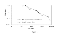
- FIG. 11 Effect of Re on the mixing time for single phase and two phase flow in lamellar channels in a geometry with fixed turn-around angle.
- FIG. 12 The extent of mixing was analyzed by mixing blue and red colours.
- the images of the micro mixer at different flow rates 0.5 ml/min, 1 ml/min, 2 ml/min, 5 ml/min, 10 ml/min, 20 ml/min)
- the present invention provides a continuous flow metallic or non-metallic micromixer assembly which comprises of mixing units having different planar features.
- the continuous flow micromixer of the present invention retains agility and re-configurability of the continuous processes and also facilitates in achieving desired mixing time and enhancing mixing and reaction.
- the present invention discloses a multimodal micromixer comprising plurality of inlets, an outlet and a plurality of channels wherein end channels comprise plurality of converging sections having width to depth ratio ranging 1:1 to 20:1, and intermediate channels having plurality of obstacles for intensification of mixing and performing the reaction in a continuous manner.
- the obstruction may be non-circular, such as triangular, rectangular or any other non-circular shape.
- the obstructions may have a non-cylindrical shape.
- the micromixer may be metallic or non-metallic. It has a machined lamellar structure.
- the obstruction may have same or lower height than the depth of machined converging section.
- the micromixer may have multi feed inlets.
- the inlet/injection ports are placed such that the axes of injection port are co-planar and perpendicular to the channel.
- the obstacles may be arranged in periodic or aperiodic sequence.
- the periodic or aperiodic sequence may be of different shaped obstacles.
- the sequence may include combination of triangular, rectangular and any other non-circular shaped obstacles.
- Each of the fluidic structures can be machined in metallic and non-metallic flat plates having respective inlet and outlet ports;
- micromixer having said plurality of machined fluidic structures achieves the desired residence time, extent of mixing, pressure drop and chemical reaction in a single phase or multiphase (gas-liquid, liquid-liquid, gas-liquid-liquid and such like) system is disclosed herein.
- the individual fluidic structures can have identical or different axis of symmetry.
- the micromixer of the present invention comprises a plurality of channels, intermediate channels, plurality of inlets [ 202 - 204 ] being co-planar and perpendicular to the channels; and an outlet [ 205 ].
- the end channels of said plurality of channels comprise of plurality of converging sections [ 702 ] having width to depth ratio ranging 1:1 to 20:1.
- the converging sections [ 702 ] are incomplete ellipse [ 701 A-C], prolate [ 701 D] or oblate [ 701 E] shaped having angle of curvature in the range of 90 to 270°.
- the ratio of radii of curvature of incomplete ellipse, prolate or oblate shaped is in the range of 0.1:10.
- the intermediate channels have at least one obstacle [ 703 ] for intensification of mixing and performing the reaction in a continuous manner.
- the obstacle/s [ 703 ] in the intermediate channel have non-circular shape selected from triangular, rectangular or any such shape,
- the converging sections [ 702 ], the obstacles [ 703 ], the inlets [ 202 - 204 ] and the outlet [ 205 ] are co-planar.
- the micro mixer [ 100 ] is a combination of two flat plates [ 102 ] and [ 103 ] joined face to face using screws or threaded nut-bolts through several end to end grooves [ 101 ].
- the flat large surface of the bottom plate [ 102 ] facing the top plate is machined partly [ 201 ] and the system is made leak proof using an o-ring or gasket that can be held in the groove [ 206 ] machined on the same flat surface [ 102 ] and the machined section has four through holes [ 202 - 205 ] that open on the other side of the bottom plate [ 102 A].
- the holes [ 202 - 204 ] act as inlets while [ 205 ] acts as outlet.
- the machined surface [ 201 ] of the bottom plate [ 102 ] includes a mixing zone [ 207 ] that occupies a substantial section of the machined area.
- the bottom plate [ 102 ] and the holes [ 202 - 205 ] are either threaded or are smooth for connecting to metallic or non-metallic straight or flexible tubes with or without the help of external connectors.
- the mixing zone [ 207 ] may be selected from one or a plurality of units selected from lamellar flow structures [ 701 ], or a sequence of sharp converging units [ 702 ] or such like arranged in varied permutations and combinations.
- the lamellar flow structures [ 701 ] comprises a cross section of geometries selected from circular, elliptical, square or rectangular or a combination of segments of an incomplete circle [ 701 A- 701 C], specifically any geometry from quarter of a circle to 3 ⁇ 4 th of complete circle in the same plane.
- the individual lamella can have the shape of an incomplete ellipse, prolate [ 701 D] or oblate [ 701 E].
- the ratio of radii of curvature of the two sides of any lamella (R1—major axis, R2—minor axis) can vary in the range of 0.1 to 10.
- the angle of curvature can vary in the range of 90° to 270°.
- the lamella having varied properties (radii, angle of curvature and diameter or cross-section shapes) can be arranged in varied permutations and combinations to achieve the desired length.
- the mixing zone may comprise of one or more rows of such combination of segments connected to each other.
- lamellar flow structures [ 701 ] can have circular or elliptical or square or rectangular cross-section and can have a combination of segments of an incomplete circle [ 701 A- 701 C], specifically any geometry from quarter of a circle to 3 ⁇ 4 th of complete circle in the same plane such that every alternate lamella is machined in two different plates [ 701 F] i.e. top plate [ 103 ] and the bottom plate [ 102 ] with slight overlap to facilitate fluid transfer from one segment to other.
- the individual lamella can have the shape of an incomplete ellipse, prolate [ 701 D] or oblate [ 701 E].
- the ratio of radii of curvature of the two sides of any lamella can vary in the range of 0.1 to 10.
- the angle of curvature can vary in the range of 90° to 270°.
- the lamella having varied properties can be arranged in varied permutations and combinations to achieve the desired length.
- the mixing zone can comprise of one or more rows of such combination of segments connected to each other.
- each of the elements of the sharp converging sections [ 702 ] may have non-cylindrical or non-circular obstacles [ 703 ] arranged in varied permutations and combinations.
- the flow obstacles [ 703 ] comprise a triangular or rectangular shape.
- the major axis of the rectangular shaped flow obstacles [ 703 ] is parallel or perpendicular to the flow direction.
- the lamellar structure [ 701 ] is a sequence of 270° turns.
- the micro mixer of the invention is useful used for carrying out the reactions selected from, but not limited to aromatic nitration (o-xylene, acetophenone, propiophenone, substituted aromatic ketones and such like), reactions involving diazonium salts and for Meerwein arylation reaction, reactions involving Bu-Li, flow synthesis of amino crotonates, sulfoxidation, and such others.
- aromatic nitration o-xylene, acetophenone, propiophenone, substituted aromatic ketones and such like
- reactions involving diazonium salts and for Meerwein arylation reaction reactions involving Bu-Li
- flow synthesis of amino crotonates sulfoxidation, and such others.
- Residence time distribution for a tracer pulse was used as a method for exploring the nature of mixing in converging section of mixer.
- a sequence of diverging sections was also used as different mixer geometry.
- the ratio of the length scale facing the fluid inlet is between 2 to 20, more specifically it was between 5 to 7.
- the RTD curves for the different sections of the micromixer are shown in FIG. 9 .
- the extent of dispersion only from the middle section comprising of converging two dimensional units ( FIG. 9A ) is quite wide as compared to the lamellar section ( FIG. 9B ) indicates that it is necessary to have the lamellar sections sandwiching the middle section to reduce the dispersion and also enhance mixing.
- the overall tracer outlet was close to Guassian indicating that the extent of dispersion was close to a plug flow reactor, which is desired.
- FIGS. 10A, 10B and 10C illustrate the effect of power consumption per unit volume on the mixing time for single phase and two phase flow in lamellar channels in a geometry with fixed turn-around angle. Mixing time was seen to decrease with increasing flow rate or the power consumption in the micromixer. The trends were identical for single phase as well as two-phase systems. This is standard for a good micromixer and indicates that constant extent of mixing can be achieved with higher power or flow rates in shorter time.
- FIG. 12 shows the pictorial view of the mixing quantification. It can be seen that in the first lamellar section mixing takes place only to some extent and it enhances rapidly when the type of mixing changes from lamellar mixing to split and recombine type of mixing. Later the second lamellar section ensures that complete mixing is achieved. From top to bottom the pictures correspond to different flow rates.
- Residence time distribution for a tracer pulse was used as a method for exploring the nature of mixing in converging section of mixer.
- a sequence of diverging sections was also used as different mixer geometry.
- the ratio of the length scale facing the fluid inlet is between 2 to 20, more specifically it was between 5 to 7.
- RTD residence time distribution
Landscapes
- Chemical & Material Sciences (AREA)
- Chemical Kinetics & Catalysis (AREA)
- Dispersion Chemistry (AREA)
- Physical Or Chemical Processes And Apparatus (AREA)
Abstract
Description
- The present invention relates to a flow micromixer composed of plurality of fluidic components which helps retain consistency and re-configurability of the continuous chemical processes with improved processing ability. More specifically, the invention relates to a multimodal micromixer composed of varied permutations and combinations of a plurality of modular elements for intensification of mixing and performing the reaction in a continuous manner.
- A continuous flow passive micromixer usually helps to achieve rapid mixing based on the geometry of the flow domain. It offers much faster mixing than the batch reactors for processing the same volume. This gives an advantage of better mixing, reduced mixing time, and consistency in the quality of mixed fluid thereby helping to achieve identical inlet conditions for reactions in a continuous reactor.
- However, Continuous reactors usually are inflexible, less agile and not very prone to process modifications. Therefore, many multi-product manufacturing modules or plants prefer batch processing.
- Converging diverging type mixers are one type of continuous mixer, which have not been widely explored to overcome this issue as it is typically perceived to be a ventury only. Prior exploration have been limited to only the converging section as mixer and residence time distribution for a tracer pulse has been used as a parameter to study the mixing performance.
- But this option does not overcome the issues of moving from batch to continuous processing.
- There have been attempts to improve micromixer designs. U.S. Pat. No. 7,753,580 discloses mixer apparatus which comprises at least one injection zone in a continuous flow path where plurality of fluids make initial contact. The injection zone has co-axial injection passage. The mixer elements comprise of a channel segment in the flow path. The channels lie on a first layer and a second layer. The channels in the first layer and the second layer are in perpendicular with each other. The mixer elements is further characterized by a chamber disposed at an end of said channel segment wherein each chamber further contains at least one obstacle. Further, the obstacle may preferably have a cylindrical shape. However, the obstacle may also take any geometrical shape and may be in series or parallel along the flow path to provide the desired flow-rate, mixing and pressure-drop.
- U.S. Pat. No. 5,904,424 discloses a device for mixing liquids, The said device has at least two microchannels issuing from at least one inlet channel. Both of the microchannels are lying in the same branching plane. The device includes a confluence element connected by a connection to said microchannels. The said connection effects a 90° rotation of the inflow of the liquid relative to the branching plane as the liquid flows from the microchannels to the confluence element. However, the channel segments in US '424 are the sections that connect the subsequent segments in a perpendicular manner and not in the same plane.
- Further, an article titled “Mixing performance of a planar micromixer with circular obstructions in a curved microchannel” by Afroz Alam et. al. numerically investigates the mixing and fluid flow in a new design of passive micromixer employing several cylindrical obstructions within a curved microchannel. Mixing in the channels is analyzed using Navier-Stokes equations and the diffusion equation between two working fluids (water and ethanol) for Reynolds numbers from 0.1 to 60. The proposed micromixer of the said paper is claimed to be shown far better mixing performance than a T-micromixer with circular obstructions and a simple curved micromixer. The effects of cross-sectional shape, height, and placement of the obstructions on mixing performance and the pressure drop of the proposed micromixer have also been evaluated. However, these obstacles are placed in straight channels.
- Another article titled “Design and Analysis of Y Shaped Micro-Mixer with Different Configuration of Obstacles” by Anil Shinde published in Sverian Scientific Vol. 1 April 2015 studies the mixing of two liquids in “Y” channel using Cosmol multyphysics, a commercial CFD tool. Obstacles located on the channel wall are used to enhance mixing in the channel, so as to reduce the mixing length. Micro channels with different geometric layout and with different shapes and sizes of obstacles such as rectangular, triangular and semicircular, are analyzed for their mixing length. The triangular obstacles within the “Y” channel gave minimum mixing length for the same distance between the obstacles.
- The inventors of the present invention have attempted to improve the mixing efficiency further without affecting its agility.
- It is an object of the invention to provide a multimodal micro mixer that provides consistent mixing without affecting its agility.
- In accordance with the object, the present invention provides novel modular reactor/micro mixer design that helps retain consistency and re-configurability of the continuous processes with better processing ability via intensification of mixing and reaction.
- In an aspect, the present invention discloses a multimodal micromixer comprising plurality of inlets, an outlet and a plurality of channels wherein end channel comprises plurality of converging sections having width to depth ratio ranging 1:1 to 20:1, and intermediate channels having plurality of obstacles for intensification of mixing and performing the reaction in a continuous manner.
- In a preferred embodiment, the obstacles may be non-circular, such as triangular, rectangular or any other non-circular shape. In another embodiment, the obstacles may have a non-cylindrical shape. The obstacles are placed in the intermediate channels only in order to enhance the mixing efficiency.
- The micromixer may be metallic or non-metallic. It has a machined lamellar structure. The obstacles may have same or lower height than the depth of machined converging section.
- In a preferred embodiment, the micromixer may have multi feed inlets. The inlet/injection ports are placed such that the axes of injection port are co-planar and perpendicular to the channel. The obstacles may be arranged in periodic or aperiodic sequence. The channels have serpentine nature.
- In another embodiment, the periodic or aperiodic sequence may be of different shaped obstacles. For example, the sequence may include combination of triangular, rectangular and any other non-circular shaped obstacles.
- In another aspect, the individual fluidic structures can have identical or different axis of symmetry.
-
FIG. 1 : Illustrates the assembled micromixer device. -
FIG. 2 : illustrates side views of micromixer inFIG. 1 . -
FIG. 3 : Illustrates side view of the details of the machined bottom plate of micromixer inFIG. 1 . -
FIG. 4 : Illustrates front view of the details of the machined bottom plate of micromixer inFIG. 1 . -
FIG. 5 : Illustrates front view of the details of the mixing zone of the micromixer inFIG. 3 . -
FIG. 6 : Illustrates the lamellar structure [701] and its variants. -
FIG. 7 : Illustrates the split lamellar structure [701]. -
FIG. 8 : Illustrates the various options of sharp edged converging section in the mixing zone of the micromixer inFIG. 3 . -
FIG. 9 : Illustrates the front view of the bottom plate [102] and the top plate [103] -
FIG. 10 : RTD for the instant device and the sequence of middle converging section of the micro mixer alone -
FIG. 11 : Effect of Re on the mixing time for single phase and two phase flow in lamellar channels in a geometry with fixed turn-around angle. -
FIG. 12 : The extent of mixing was analyzed by mixing blue and red colours. The images of the micro mixer at different flow rates (0.5 ml/min, 1 ml/min, 2 ml/min, 5 ml/min, 10 ml/min, 20 ml/min) - The present invention provides a continuous flow metallic or non-metallic micromixer assembly which comprises of mixing units having different planar features.
- The continuous flow micromixer of the present invention retains agility and re-configurability of the continuous processes and also facilitates in achieving desired mixing time and enhancing mixing and reaction.
- Accordingly, the present invention discloses a multimodal micromixer comprising plurality of inlets, an outlet and a plurality of channels wherein end channels comprise plurality of converging sections having width to depth ratio ranging 1:1 to 20:1, and intermediate channels having plurality of obstacles for intensification of mixing and performing the reaction in a continuous manner.
- In a preferred embodiment, the obstruction may be non-circular, such as triangular, rectangular or any other non-circular shape. In another embodiment, the obstructions may have a non-cylindrical shape.
- The micromixer may be metallic or non-metallic. It has a machined lamellar structure. The obstruction may have same or lower height than the depth of machined converging section.
- In a preferred embodiment, the micromixer may have multi feed inlets. The inlet/injection ports are placed such that the axes of injection port are co-planar and perpendicular to the channel. The obstacles may be arranged in periodic or aperiodic sequence.
- In another embodiment, the periodic or aperiodic sequence may be of different shaped obstacles. For example, the sequence may include combination of triangular, rectangular and any other non-circular shaped obstacles.
- Each of the fluidic structures can be machined in metallic and non-metallic flat plates having respective inlet and outlet ports;
- The selection of right combination of lamellar structures (radii of curvature, shape of cross-section, flow area, plane of machining and number of elements) and the converging unit (number of units, dimensions, type of obstruction, etc,) is decided upon the physicochemical properties of fluids to be mixed and the available pressure drop;
- The micromixer having said plurality of machined fluidic structures achieves the desired residence time, extent of mixing, pressure drop and chemical reaction in a single phase or multiphase (gas-liquid, liquid-liquid, gas-liquid-liquid and such like) system is disclosed herein.
- The individual fluidic structures can have identical or different axis of symmetry.
- The invention will now be described in detail in connection with certain preferred and optional embodiments by way of figures, so that various aspects thereof may be more fully understood and appreciated. However, the figures are for the purpose of understanding the embodiments of the invention and should not be construed as limiting the scope of the invention. Any modifications in the embodiments may be considered as obvious to person skilled in the art.
- With reference to
FIGS. 1-9 , the micromixer of the present invention comprises a plurality of channels, intermediate channels, plurality of inlets [202-204] being co-planar and perpendicular to the channels; and an outlet [205]. The end channels of said plurality of channels comprise of plurality of converging sections [702] having width to depth ratio ranging 1:1 to 20:1. The converging sections [702] are incomplete ellipse [701A-C], prolate [701D] or oblate [701E] shaped having angle of curvature in the range of 90 to 270°. The ratio of radii of curvature of incomplete ellipse, prolate or oblate shaped is in the range of 0.1:10. The intermediate channels have at least one obstacle [703] for intensification of mixing and performing the reaction in a continuous manner. The obstacle/s [703] in the intermediate channel have non-circular shape selected from triangular, rectangular or any such shape, The converging sections [702], the obstacles [703], the inlets [202-204] and the outlet [205] are co-planar. - The micro mixer [100] is a combination of two flat plates [102] and [103] joined face to face using screws or threaded nut-bolts through several end to end grooves [101].
- The flat large surface of the bottom plate [102] facing the top plate is machined partly [201] and the system is made leak proof using an o-ring or gasket that can be held in the groove [206] machined on the same flat surface [102] and the machined section has four through holes [202-205] that open on the other side of the bottom plate [102A]. The holes [202-204] act as inlets while [205] acts as outlet.
- The machined surface [201] of the bottom plate [102] includes a mixing zone [207] that occupies a substantial section of the machined area.
- The bottom plate [102] and the holes [202-205] are either threaded or are smooth for connecting to metallic or non-metallic straight or flexible tubes with or without the help of external connectors.
- The mixing zone [207] may be selected from one or a plurality of units selected from lamellar flow structures [701], or a sequence of sharp converging units [702] or such like arranged in varied permutations and combinations.
- In another embodiment, the lamellar flow structures [701] comprises a cross section of geometries selected from circular, elliptical, square or rectangular or a combination of segments of an incomplete circle [701A-701C], specifically any geometry from quarter of a circle to ¾th of complete circle in the same plane. The individual lamella can have the shape of an incomplete ellipse, prolate [701D] or oblate [701E]. The ratio of radii of curvature of the two sides of any lamella (R1—major axis, R2—minor axis) can vary in the range of 0.1 to 10. The angle of curvature can vary in the range of 90° to 270°. The lamella having varied properties (radii, angle of curvature and diameter or cross-section shapes) can be arranged in varied permutations and combinations to achieve the desired length. The mixing zone may comprise of one or more rows of such combination of segments connected to each other.
- In another embodiment of the lamellar flow structures [701], can have circular or elliptical or square or rectangular cross-section and can have a combination of segments of an incomplete circle [701A-701C], specifically any geometry from quarter of a circle to ¾th of complete circle in the same plane such that every alternate lamella is machined in two different plates [701F] i.e. top plate [103] and the bottom plate [102] with slight overlap to facilitate fluid transfer from one segment to other. The individual lamella can have the shape of an incomplete ellipse, prolate [701D] or oblate [701E]. The ratio of radii of curvature of the two sides of any lamella (R1—major axis, R2—minor axis) can vary in the range of 0.1 to 10. The angle of curvature can vary in the range of 90° to 270°. The lamella having varied properties (radii, angle of curvature and diameter or cross-section shapes) can be arranged in varied permutations and combinations to achieve the desired length. The mixing zone can comprise of one or more rows of such combination of segments connected to each other.
- In a preferred embodiment, each of the elements of the sharp converging sections [702] may have non-cylindrical or non-circular obstacles [703] arranged in varied permutations and combinations. In one embodiment, the flow obstacles [703] comprise a triangular or rectangular shape. In another embodiment, the major axis of the rectangular shaped flow obstacles [703] is parallel or perpendicular to the flow direction.
- In a preferred embodiment, the lamellar structure [701] is a sequence of 270° turns.
- The micro mixer of the invention is useful used for carrying out the reactions selected from, but not limited to aromatic nitration (o-xylene, acetophenone, propiophenone, substituted aromatic ketones and such like), reactions involving diazonium salts and for Meerwein arylation reaction, reactions involving Bu-Li, flow synthesis of amino crotonates, sulfoxidation, and such others.
- Residence time distribution for a tracer pulse was used as a method for exploring the nature of mixing in converging section of mixer. In addition to the converging sections, a sequence of diverging sections was also used as different mixer geometry. For the converging section the ratio of the length scale facing the fluid inlet is between 2 to 20, more specifically it was between 5 to 7.
- The RTD curves for the different sections of the micromixer are shown in
FIG. 9 . The extent of dispersion only from the middle section comprising of converging two dimensional units (FIG. 9A ) is quite wide as compared to the lamellar section (FIG. 9B ) indicates that it is necessary to have the lamellar sections sandwiching the middle section to reduce the dispersion and also enhance mixing. The overall tracer outlet was close to Guassian indicating that the extent of dispersion was close to a plug flow reactor, which is desired. -
FIGS. 10A, 10B and 10C illustrate the effect of power consumption per unit volume on the mixing time for single phase and two phase flow in lamellar channels in a geometry with fixed turn-around angle. Mixing time was seen to decrease with increasing flow rate or the power consumption in the micromixer. The trends were identical for single phase as well as two-phase systems. This is standard for a good micromixer and indicates that constant extent of mixing can be achieved with higher power or flow rates in shorter time. - Following examples are given by way of illustration and therefore should not be construed to limit the scope of the invention.
- The extent of mixing was analyzed by mixing blue and red colours. The images of the micromixer at different flow rates (0.5 ml/min, 1 ml/min, 2 ml/min, 5 ml/min, 10 ml/min, 20 ml/min) are given in
FIG. 12 which shows the pictorial view of the mixing quantification. It can be seen that in the first lamellar section mixing takes place only to some extent and it enhances rapidly when the type of mixing changes from lamellar mixing to split and recombine type of mixing. Later the second lamellar section ensures that complete mixing is achieved. From top to bottom the pictures correspond to different flow rates. - Residence time distribution for a tracer pulse was used as a method for exploring the nature of mixing in converging section of mixer. In addition to the converging sections, a sequence of diverging sections was also used as different mixer geometry. For the converging section the ratio of the length scale facing the fluid inlet is between 2 to 20, more specifically it was between 5 to 7. When fluids flow through curvilinear channels, they experience inertial forces acting to direct axial motion and centrifugal forces acting along the radius of curvature. When the fluid flows through the lamellar channels, a mismatch of velocity between the fluid in the centre and the fluid near the wall region causes secondary flows. Fluid elements at the channel centreline tend to flow outward around the curve and since the channel is enclosed, the fluid near the walls re circulates inward creating two symmetric vortices. The residence time distribution (RTD) which actually indicates the extent of dispersion in the system were measured for the complete device and also the sequence of middle converging section of the micro mixer alone. The RTD curves are illustrated in
FIGS. 11 and 12 . - Reaction of bromobenzene in acetic acid (bromobenzene to acetic acid volume ratio was kept at 1:15.) with nitrating mixture (60:40 v/v, 68% HNO3 & H2SO4 respectively) was carried out with the micromixer followed by residence time tube. Complete conversion was achieved at 30° C. and residence time of 60 minutes. Para to ortho isomer ratio was 2.82.
- Reaction of bromobenzene in acetic acid (bromobenzene to acetic acid volume ratio was kept at 1:15.) with nitrating mixture (60:40 v/v, 68% HNO3 & H2SO4 respectively) was carried out with the micromixer followed by residence time tube. Complete conversion was achieved at 80° C. and residence time of 15 minutes. Para to ortho isomer ratio was 2.82.
Claims (10)
Applications Claiming Priority (3)
| Application Number | Priority Date | Filing Date | Title |
|---|---|---|---|
| IN1022/DEL/2015 | 2015-04-13 | ||
| IN1022DE2015 | 2015-04-13 | ||
| PCT/IN2016/050108 WO2016166771A1 (en) | 2015-04-13 | 2016-04-13 | Continuous micro mixer |
Publications (2)
| Publication Number | Publication Date |
|---|---|
| US20180117543A1 true US20180117543A1 (en) | 2018-05-03 |
| US10857508B2 US10857508B2 (en) | 2020-12-08 |
Family
ID=56203452
Family Applications (1)
| Application Number | Title | Priority Date | Filing Date |
|---|---|---|---|
| US15/566,020 Active 2037-07-26 US10857508B2 (en) | 2015-04-13 | 2016-04-13 | Continuous micro mixer |
Country Status (2)
| Country | Link |
|---|---|
| US (1) | US10857508B2 (en) |
| WO (1) | WO2016166771A1 (en) |
Cited By (2)
| Publication number | Priority date | Publication date | Assignee | Title |
|---|---|---|---|---|
| CN110947329A (en) * | 2019-11-29 | 2020-04-03 | 南昌航空大学 | A sawtooth passive micro-mixer |
| CN112705133A (en) * | 2021-03-09 | 2021-04-27 | 宁夏宁东泰和新材有限公司 | Preparation system of polyurethane elastic fiber |
Citations (6)
| Publication number | Priority date | Publication date | Assignee | Title |
|---|---|---|---|---|
| US6176911B1 (en) * | 1999-04-28 | 2001-01-23 | Xerox Corporation | Ink compositions |
| US20050276160A1 (en) * | 2004-06-11 | 2005-12-15 | Pierre Woehl | Microstructure designs for optimizing mixing and pressure drop |
| US20060087918A1 (en) * | 2003-06-11 | 2006-04-27 | Agency For Science, Technology And Research | Micromixer apparatus and methods of using same |
| US20170239655A1 (en) * | 2014-08-26 | 2017-08-24 | Narwhal Analytical Corporation (Ontario Corporation Number 002408580) | Mini-fluidics cassette for colorimetric nutrient analysis and a method of using same |
| US9908117B2 (en) * | 2014-09-22 | 2018-03-06 | Industry-Academic Cooperation Foundation Yonsei University | Microfluidic separation device, separation method using the same and kit for separating circulating rare cells from blood using the same |
| US10233482B2 (en) * | 2014-09-10 | 2019-03-19 | The United States Of America, As Represented By The Secretary Of Agriculture | Micro-fluidic mixer and method of determining pathogen inactivation via antimicrobial solutions |
Family Cites Families (6)
| Publication number | Priority date | Publication date | Assignee | Title |
|---|---|---|---|---|
| DE19511603A1 (en) | 1995-03-30 | 1996-10-02 | Norbert Dr Ing Schwesinger | Device for mixing small amounts of liquid |
| US7485454B1 (en) | 2000-03-10 | 2009-02-03 | Bioprocessors Corp. | Microreactor |
| EP2017000B1 (en) * | 2007-07-11 | 2012-09-05 | Corning Incorporated | Process intensified microfluidic devices |
| US20110150703A1 (en) * | 2008-07-18 | 2011-06-23 | Castro Gustavo H | Tortuous path static mixers and fluid systems including the same |
| CA2853316C (en) | 2011-10-25 | 2018-11-27 | The University Of British Columbia | Limit size lipid nanoparticles and related methods |
| US20140146636A1 (en) * | 2012-11-28 | 2014-05-29 | Photronics, Inc. | Mixer chip |
-
2016
- 2016-04-13 US US15/566,020 patent/US10857508B2/en active Active
- 2016-04-13 WO PCT/IN2016/050108 patent/WO2016166771A1/en not_active Ceased
Patent Citations (6)
| Publication number | Priority date | Publication date | Assignee | Title |
|---|---|---|---|---|
| US6176911B1 (en) * | 1999-04-28 | 2001-01-23 | Xerox Corporation | Ink compositions |
| US20060087918A1 (en) * | 2003-06-11 | 2006-04-27 | Agency For Science, Technology And Research | Micromixer apparatus and methods of using same |
| US20050276160A1 (en) * | 2004-06-11 | 2005-12-15 | Pierre Woehl | Microstructure designs for optimizing mixing and pressure drop |
| US20170239655A1 (en) * | 2014-08-26 | 2017-08-24 | Narwhal Analytical Corporation (Ontario Corporation Number 002408580) | Mini-fluidics cassette for colorimetric nutrient analysis and a method of using same |
| US10233482B2 (en) * | 2014-09-10 | 2019-03-19 | The United States Of America, As Represented By The Secretary Of Agriculture | Micro-fluidic mixer and method of determining pathogen inactivation via antimicrobial solutions |
| US9908117B2 (en) * | 2014-09-22 | 2018-03-06 | Industry-Academic Cooperation Foundation Yonsei University | Microfluidic separation device, separation method using the same and kit for separating circulating rare cells from blood using the same |
Cited By (2)
| Publication number | Priority date | Publication date | Assignee | Title |
|---|---|---|---|---|
| CN110947329A (en) * | 2019-11-29 | 2020-04-03 | 南昌航空大学 | A sawtooth passive micro-mixer |
| CN112705133A (en) * | 2021-03-09 | 2021-04-27 | 宁夏宁东泰和新材有限公司 | Preparation system of polyurethane elastic fiber |
Also Published As
| Publication number | Publication date |
|---|---|
| WO2016166771A4 (en) | 2017-01-12 |
| WO2016166771A1 (en) | 2016-10-20 |
| US10857508B2 (en) | 2020-12-08 |
Similar Documents
| Publication | Publication Date | Title |
|---|---|---|
| JP5604038B2 (en) | Reaction apparatus and reaction plant | |
| JP6674933B2 (en) | Process-enhanced microfluidic device | |
| US12194428B2 (en) | Multi-layered micro-channel mixer and method for mixing fluids | |
| CN103638853B (en) | A kind of S type passive type micro-mixer | |
| CN102355942B (en) | Coaxial compact static mixer and use thereof | |
| CN102395425B (en) | Flow module | |
| US20120035392A1 (en) | Tubular flow type reactor | |
| US12163118B2 (en) | Continuous flow reactor for viral inactivation | |
| EP2608877A1 (en) | Micro-fluidic device | |
| US20170056846A1 (en) | Static mixer | |
| EP2113558B1 (en) | Microreactor | |
| US20130022507A1 (en) | Tubular flow reactor | |
| US10857508B2 (en) | Continuous micro mixer | |
| TW202023679A (en) | Microchannel reaction appratus | |
| CN112403413B (en) | Integrated countercurrent strengthening microreactor | |
| CN106999875B (en) | Fluid mixing structure, continuous reaction unit, continuous reaction reactor and methods of using the same | |
| CN111001348A (en) | Multi-unit mixer | |
| EP3574276A1 (en) | Compact coiled flow inverters as in-line mixers | |
| GB2572589A (en) | Modular fluid flow reactor | |
| CN115845685B (en) | Countercurrent jet annular gap micromixer | |
| US20250283490A1 (en) | Manifold design for uniform flow | |
| EP4593998A1 (en) | Apparatus for passive mixing of multiphase flow | |
| HK1235342A1 (en) | Fluid mixing structure, continuous reaction unit, continuous reaction reactor and method of using the same | |
| JP2010012363A (en) | Micromixer | |
| PL235456B1 (en) | Static flow mixer |
Legal Events
| Date | Code | Title | Description |
|---|---|---|---|
| FEPP | Fee payment procedure |
Free format text: ENTITY STATUS SET TO UNDISCOUNTED (ORIGINAL EVENT CODE: BIG.); ENTITY STATUS OF PATENT OWNER: LARGE ENTITY |
|
| STPP | Information on status: patent application and granting procedure in general |
Free format text: DOCKETED NEW CASE - READY FOR EXAMINATION |
|
| STPP | Information on status: patent application and granting procedure in general |
Free format text: NON FINAL ACTION MAILED |
|
| STPP | Information on status: patent application and granting procedure in general |
Free format text: FINAL REJECTION MAILED |
|
| STPP | Information on status: patent application and granting procedure in general |
Free format text: NOTICE OF ALLOWANCE MAILED -- APPLICATION RECEIVED IN OFFICE OF PUBLICATIONS |
|
| AS | Assignment |
Owner name: COUNCIL OF SCIENTIFIC & INDUSTRIAL RESEARCH, INDIA Free format text: ASSIGNMENT OF ASSIGNORS INTEREST;ASSIGNORS:KULKARNI, AMOL ARVIND;RANADE, VIVEK VINAYAK;REEL/FRAME:054004/0401 Effective date: 20201001 |
|
| STPP | Information on status: patent application and granting procedure in general |
Free format text: PUBLICATIONS -- ISSUE FEE PAYMENT VERIFIED |
|
| STCF | Information on status: patent grant |
Free format text: PATENTED CASE |
|
| MAFP | Maintenance fee payment |
Free format text: PAYMENT OF MAINTENANCE FEE, 4TH YEAR, LARGE ENTITY (ORIGINAL EVENT CODE: M1551); ENTITY STATUS OF PATENT OWNER: LARGE ENTITY Year of fee payment: 4 |