US20180098786A1 - Apparatus and method for accessing an epidural space - Google Patents
Apparatus and method for accessing an epidural space Download PDFInfo
- Publication number
- US20180098786A1 US20180098786A1 US15/638,777 US201715638777A US2018098786A1 US 20180098786 A1 US20180098786 A1 US 20180098786A1 US 201715638777 A US201715638777 A US 201715638777A US 2018098786 A1 US2018098786 A1 US 2018098786A1
- Authority
- US
- United States
- Prior art keywords
- obturator
- handle
- distal end
- hollow needle
- needle
- Prior art date
- Legal status (The legal status is an assumption and is not a legal conclusion. Google has not performed a legal analysis and makes no representation as to the accuracy of the status listed.)
- Granted
Links
- 238000000034 method Methods 0.000 title claims description 12
- 239000000463 material Substances 0.000 claims description 4
- 239000003814 drug Substances 0.000 description 3
- 229940079593 drug Drugs 0.000 description 3
- 230000008901 benefit Effects 0.000 description 2
- 238000002347 injection Methods 0.000 description 2
- 239000007924 injection Substances 0.000 description 2
- -1 polyethylene Polymers 0.000 description 2
- 229920000642 polymer Polymers 0.000 description 2
- 210000003813 thumb Anatomy 0.000 description 2
- 239000012780 transparent material Substances 0.000 description 2
- 239000004698 Polyethylene Substances 0.000 description 1
- 206010040030 Sensory loss Diseases 0.000 description 1
- FAPWRFPIFSIZLT-UHFFFAOYSA-M Sodium chloride Chemical compound [Na+].[Cl-] FAPWRFPIFSIZLT-UHFFFAOYSA-M 0.000 description 1
- 230000036592 analgesia Effects 0.000 description 1
- 230000000202 analgesic effect Effects 0.000 description 1
- 230000000903 blocking effect Effects 0.000 description 1
- 239000002872 contrast media Substances 0.000 description 1
- 238000002692 epidural anesthesia Methods 0.000 description 1
- 210000003811 finger Anatomy 0.000 description 1
- 210000004247 hand Anatomy 0.000 description 1
- 239000003589 local anesthetic agent Substances 0.000 description 1
- 239000002184 metal Substances 0.000 description 1
- 238000012986 modification Methods 0.000 description 1
- 230000004048 modification Effects 0.000 description 1
- 239000004084 narcotic analgesic agent Substances 0.000 description 1
- 210000004126 nerve fiber Anatomy 0.000 description 1
- 239000004033 plastic Substances 0.000 description 1
- 229920003023 plastic Polymers 0.000 description 1
- 229920000515 polycarbonate Polymers 0.000 description 1
- 239000004417 polycarbonate Substances 0.000 description 1
- 229920000573 polyethylene Polymers 0.000 description 1
- 229920001343 polytetrafluoroethylene Polymers 0.000 description 1
- 239000004810 polytetrafluoroethylene Substances 0.000 description 1
- 230000008054 signal transmission Effects 0.000 description 1
- 239000011780 sodium chloride Substances 0.000 description 1
- 210000000701 subdural space Anatomy 0.000 description 1
- 239000000126 substance Substances 0.000 description 1
- 230000001225 therapeutic effect Effects 0.000 description 1
Images

Classifications
-
- A—HUMAN NECESSITIES
- A61—MEDICAL OR VETERINARY SCIENCE; HYGIENE
- A61B—DIAGNOSIS; SURGERY; IDENTIFICATION
- A61B17/00—Surgical instruments, devices or methods
- A61B17/34—Trocars; Puncturing needles
- A61B17/3401—Puncturing needles for the peridural or subarachnoid space or the plexus, e.g. for anaesthesia
-
- A—HUMAN NECESSITIES
- A61—MEDICAL OR VETERINARY SCIENCE; HYGIENE
- A61M—DEVICES FOR INTRODUCING MEDIA INTO, OR ONTO, THE BODY; DEVICES FOR TRANSDUCING BODY MEDIA OR FOR TAKING MEDIA FROM THE BODY; DEVICES FOR PRODUCING OR ENDING SLEEP OR STUPOR
- A61M25/00—Catheters; Hollow probes
- A61M25/01—Introducing, guiding, advancing, emplacing or holding catheters
- A61M25/06—Body-piercing guide needles or the like
- A61M25/065—Guide needles
-
- A—HUMAN NECESSITIES
- A61—MEDICAL OR VETERINARY SCIENCE; HYGIENE
- A61B—DIAGNOSIS; SURGERY; IDENTIFICATION
- A61B17/00—Surgical instruments, devices or methods
- A61B17/34—Trocars; Puncturing needles
-
- A—HUMAN NECESSITIES
- A61—MEDICAL OR VETERINARY SCIENCE; HYGIENE
- A61B—DIAGNOSIS; SURGERY; IDENTIFICATION
- A61B17/00—Surgical instruments, devices or methods
- A61B17/34—Trocars; Puncturing needles
- A61B17/3415—Trocars; Puncturing needles for introducing tubes or catheters, e.g. gastrostomy tubes, drain catheters
-
- A—HUMAN NECESSITIES
- A61—MEDICAL OR VETERINARY SCIENCE; HYGIENE
- A61M—DEVICES FOR INTRODUCING MEDIA INTO, OR ONTO, THE BODY; DEVICES FOR TRANSDUCING BODY MEDIA OR FOR TAKING MEDIA FROM THE BODY; DEVICES FOR PRODUCING OR ENDING SLEEP OR STUPOR
- A61M25/00—Catheters; Hollow probes
- A61M25/01—Introducing, guiding, advancing, emplacing or holding catheters
- A61M25/06—Body-piercing guide needles or the like
-
- A—HUMAN NECESSITIES
- A61—MEDICAL OR VETERINARY SCIENCE; HYGIENE
- A61M—DEVICES FOR INTRODUCING MEDIA INTO, OR ONTO, THE BODY; DEVICES FOR TRANSDUCING BODY MEDIA OR FOR TAKING MEDIA FROM THE BODY; DEVICES FOR PRODUCING OR ENDING SLEEP OR STUPOR
- A61M5/00—Devices for bringing media into the body in a subcutaneous, intra-vascular or intramuscular way; Accessories therefor, e.g. filling or cleaning devices, arm-rests
- A61M5/14—Infusion devices, e.g. infusing by gravity; Blood infusion; Accessories therefor
- A61M5/158—Needles for infusions; Accessories therefor, e.g. for inserting infusion needles, or for holding them on the body
-
- A—HUMAN NECESSITIES
- A61—MEDICAL OR VETERINARY SCIENCE; HYGIENE
- A61B—DIAGNOSIS; SURGERY; IDENTIFICATION
- A61B17/00—Surgical instruments, devices or methods
- A61B17/34—Trocars; Puncturing needles
- A61B17/3494—Trocars; Puncturing needles with safety means for protection against accidental cutting or pricking, e.g. limiting insertion depth, pressure sensors
- A61B17/3496—Protecting sleeves or inner probes; Retractable tips
-
- A—HUMAN NECESSITIES
- A61—MEDICAL OR VETERINARY SCIENCE; HYGIENE
- A61B—DIAGNOSIS; SURGERY; IDENTIFICATION
- A61B17/00—Surgical instruments, devices or methods
- A61B2017/0046—Surgical instruments, devices or methods with a releasable handle; with handle and operating part separable
-
- A—HUMAN NECESSITIES
- A61—MEDICAL OR VETERINARY SCIENCE; HYGIENE
- A61B—DIAGNOSIS; SURGERY; IDENTIFICATION
- A61B17/00—Surgical instruments, devices or methods
- A61B2017/0046—Surgical instruments, devices or methods with a releasable handle; with handle and operating part separable
- A61B2017/00469—Surgical instruments, devices or methods with a releasable handle; with handle and operating part separable for insertion of instruments, e.g. guide wire, optical fibre
-
- A—HUMAN NECESSITIES
- A61—MEDICAL OR VETERINARY SCIENCE; HYGIENE
- A61B—DIAGNOSIS; SURGERY; IDENTIFICATION
- A61B90/00—Instruments, implements or accessories specially adapted for surgery or diagnosis and not covered by any of the groups A61B1/00 - A61B50/00, e.g. for luxation treatment or for protecting wound edges
- A61B90/08—Accessories or related features not otherwise provided for
- A61B2090/0807—Indication means
- A61B2090/0811—Indication means for the position of a particular part of an instrument with respect to the rest of the instrument, e.g. position of the anvil of a stapling instrument
-
- A—HUMAN NECESSITIES
- A61—MEDICAL OR VETERINARY SCIENCE; HYGIENE
- A61M—DEVICES FOR INTRODUCING MEDIA INTO, OR ONTO, THE BODY; DEVICES FOR TRANSDUCING BODY MEDIA OR FOR TAKING MEDIA FROM THE BODY; DEVICES FOR PRODUCING OR ENDING SLEEP OR STUPOR
- A61M5/00—Devices for bringing media into the body in a subcutaneous, intra-vascular or intramuscular way; Accessories therefor, e.g. filling or cleaning devices, arm-rests
- A61M5/14—Infusion devices, e.g. infusing by gravity; Blood infusion; Accessories therefor
- A61M5/158—Needles for infusions; Accessories therefor, e.g. for inserting infusion needles, or for holding them on the body
- A61M2005/1585—Needle inserters
-
- A—HUMAN NECESSITIES
- A61—MEDICAL OR VETERINARY SCIENCE; HYGIENE
- A61M—DEVICES FOR INTRODUCING MEDIA INTO, OR ONTO, THE BODY; DEVICES FOR TRANSDUCING BODY MEDIA OR FOR TAKING MEDIA FROM THE BODY; DEVICES FOR PRODUCING OR ENDING SLEEP OR STUPOR
- A61M5/00—Devices for bringing media into the body in a subcutaneous, intra-vascular or intramuscular way; Accessories therefor, e.g. filling or cleaning devices, arm-rests
- A61M5/14—Infusion devices, e.g. infusing by gravity; Blood infusion; Accessories therefor
- A61M5/158—Needles for infusions; Accessories therefor, e.g. for inserting infusion needles, or for holding them on the body
- A61M2005/1586—Holding accessories for holding infusion needles on the body
-
- A—HUMAN NECESSITIES
- A61—MEDICAL OR VETERINARY SCIENCE; HYGIENE
- A61M—DEVICES FOR INTRODUCING MEDIA INTO, OR ONTO, THE BODY; DEVICES FOR TRANSDUCING BODY MEDIA OR FOR TAKING MEDIA FROM THE BODY; DEVICES FOR PRODUCING OR ENDING SLEEP OR STUPOR
- A61M25/00—Catheters; Hollow probes
- A61M2025/0007—Epidural catheters
-
- A—HUMAN NECESSITIES
- A61—MEDICAL OR VETERINARY SCIENCE; HYGIENE
- A61M—DEVICES FOR INTRODUCING MEDIA INTO, OR ONTO, THE BODY; DEVICES FOR TRANSDUCING BODY MEDIA OR FOR TAKING MEDIA FROM THE BODY; DEVICES FOR PRODUCING OR ENDING SLEEP OR STUPOR
- A61M25/00—Catheters; Hollow probes
- A61M25/01—Introducing, guiding, advancing, emplacing or holding catheters
- A61M2025/0175—Introducing, guiding, advancing, emplacing or holding catheters having telescopic features, interengaging nestable members movable in relations to one another
-
- A—HUMAN NECESSITIES
- A61—MEDICAL OR VETERINARY SCIENCE; HYGIENE
- A61M—DEVICES FOR INTRODUCING MEDIA INTO, OR ONTO, THE BODY; DEVICES FOR TRANSDUCING BODY MEDIA OR FOR TAKING MEDIA FROM THE BODY; DEVICES FOR PRODUCING OR ENDING SLEEP OR STUPOR
- A61M2210/00—Anatomical parts of the body
- A61M2210/10—Trunk
- A61M2210/1003—Spinal column
Definitions
- the present invention relates to administering epidurals and, more particularly, to an apparatus and method for accessing an epidural space.
- Epidural administration is a medical route of administration in which a drug or contrast agent is injected into the epidural space of the spinal column. Techniques such as epidural analgesia and epidural anesthesia employ this route of administration.
- the epidural route is frequently employed by certain physicians and nurse anesthetists to administer diagnostic and therapeutic chemical substances, as well as certain analgesic and local anesthetic agents.
- Epidural techniques frequently involve injection of drugs through a catheter placed into the epidural space. The injection can result in a loss of sensation by blocking the transmission of signals through nerve fibers in or near the spinal column.
- an apparatus for accessing an epidural space comprises: a handle comprising a top end and a bottom end and forming a channel therethrough; a hollow needle comprising a proximal end and a distal end, wherein the proximal end extends from the bottom end of the handle and is aligned with the channel, and the distal end comprises a pointed tip; and an obturator disposed within the hollow needle and the channel of the handle, wherein the obturator comprises a proximal end and a distal end, wherein the distal end is blunt and is extending beyond the distal end of the needle, and the proximal end is extending beyond the channel at the top end of the handle.
- a method of accessing an epidural space comprises the steps of: providing an apparatus comprising: a hollow needle comprising a proximal end and a distal end comprising a pointed tip; and an obturator disposed within the hollow needle, wherein the obturator comprises a proximal end and a distal end, wherein the distal end is blunt and is biased to extend beyond the distal end of the hollow needle, and the proximal end is extending beyond the proximal end of the hollow needle; piercing tissue with the pointed tip of the needle, wherein the distal end of obturator recedes into the needle against the bias; and reaching an epidural space with the needle, wherein the distal end is biased back to extend beyond the distal end of the needle due to a lack of tissue within the epidural space.
- FIG. 1 is a perspective view of an embodiment of the present invention
- FIG. 2 is a detail truncated perspective view of the present invention shown in an exemplary deployed position
- FIG. 3 is a detail truncated perspective view of the present invention shown in an exemplary recessed position
- FIG. 4 is a section detail view illustrating a needle of the present invention entering tissue with an obturator recessed within the needle;
- FIG. 5 is a section detail view of the present invention taken along line 4 - 4 in FIG. 3 ;
- FIG. 6 is a section detail view illustrating a needle of the present invention entering epidural space with an obturator extending from the needle;
- FIG. 7 is a section detail view of the present invention taken along line 7 - 7 in FIG. 2 ;
- FIG. 8 is a section detail view of the present invention taken along line 8 - 8 in FIG. 7 ;
- FIG. 9 is a detail perspective view of an embodiment of the present invention.
- FIG. 10 is an exploded view of an embodiment of the present invention.
- FIG. 11 is a bottom perspective view of an embodiment of the present invention.
- FIG. 12 is a perspective view of an embodiment of the present invention.
- FIG. 13 is a section detail view of the present invention taken along line 13 - 13 in FIG. 12 ;
- FIG. 14 is a section detail view of the present invention shown in a recessed configuration
- FIG. 15 is a detail perspective view of an embodiment of the present invention.
- FIG. 16 is a detail exploded view of an embodiment of the present invention.
- the present invention includes an apparatus 10 for locating and accessing an epidural space 48 within a patient.
- the apparatus 10 includes a handle 12 having a top end and a bottom end.
- a handle channel 16 is formed through the handle 12 running from the top end to the bottom end.
- a proximal end of a hollow needle 22 extends from the bottom end of the handle 12 and aligns with the handle channel 16 .
- a distal end of the hollow needle 22 is sharp and pointed.
- An obturator 36 is disposed within the hollow needle 22 and the handle channel 16 .
- a distal end of the obturator 36 is rounded and blunt and extends from the distal end of the hollow needle 22 .
- a proximal end of the obturator 36 extends beyond the handle channel 16 at the top end of the handle 12 .
- the hollow needle 22 may be made of an elongated hollow tube of a rigid material, such as metal. As mentioned above, the distal end of the hollow needle 22 is sharp and pointed to easily pierce the skin and tissue 46 of the patient. In certain embodiments, the sharp and pointed end may be beveled.
- the obturator 36 may include an elongated shaft 40 that fits within the hollow needle 22 .
- the obturator 36 may be made of a soft flexible material, such as a polymer.
- the polymer may be plastic, biocompatible polyethylene, polytetrafluoroethylene, polycarbonate and the like.
- the obturator 36 may further include a stopper 42 at the proximal end.
- the stopper 42 has larger diameter than the handle channel 16 preventing the proximal end of the obturator 36 from entering the handle channel 16 and the hollow needle 22 .
- a shaft 38 upwardly extends from the stopper 42 .
- the handle 12 of the present invention is used to manipulate the hollow needle 22 to accurately pierce a user's tissue 46 .
- the handle 12 may include a platform 14 having laterally extending arms.
- a top protrusion 20 may extend upwardly from a top surface of the platform 14 .
- a bottom protrusion may extend downwardly from the bottom surface of the platform 14 .
- the handle channel 16 runs through the top protrusion 20 , the platform 14 and the bottom protrusion.
- the present invention may further include an obturator housing 24 .
- the stopper 42 and the shaft 38 may be disposed within the obturator housing 24 .
- the obturator housing 24 may quickly connect and disconnect with the handle 12 so that the obturator 36 may be quickly removed once the epidural space 40 is located.
- the obturator housing 24 may include a top end and a bottom end. The bottom end includes a housing channel 28 aligned with the handle channel 16 .
- An internal cavity 26 is formed in between the top end and the bottom end.
- the stopper and shaft 38 are disposed within the internal cavity 26 .
- the obturator 36 runs through the housing channel 28 and into the handle channel 16 .
- the distal end of the obturator 36 is biased to extend beyond the distal end of the hollow needle 22 .
- the obturator 36 recesses into the hollow needle 22 and the hollow needle 22 pierces the tissue 46 .
- the distal end of the obturator 36 biases back to the extended position, indicating to the user that the hollow needle 22 has reached the epidural space 48 .
- the apparatus 10 includes an automatic recessed and protruding mechanism.
- a spring 44 is disposed around the shaft 38 .
- the spring 44 abuts against the stopper 42 and is disposed in between the stopper 42 and the top end of the obturator housing 24 .
- a gap 32 is formed at the top end of the obturator housing 24 in which a top end of the shaft 38 fits within.
- the spring 44 biases the distal end of the obturator 36 out of the distal end of the hollow needle 22 .
- the obturator 36 presses against the tissue 46 , the obturator 36 is pushed upwards so that the shaft 38 enters the gap 32 and the distal end recesses within the hollow needle 22 .
- a colored strip may be printed on the shaft 38 and a portion of the obturator housing 24 is made of a transparent material.
- the colored strip is positioned to disappear when the shaft 38 is disposed within the gap 32 .
- the colored strip is revealed through the transparent material when the shaft 38 biases out of the gap 32 . Therefore, the user is easily able to determine when the end of the hollow needle has entered the epidural space 48 .
- a locking slot 18 may be formed on the top of the top protrusion 20 of the handle 12 .
- Locking lets 34 may extend downwardly from the bottom end of the obturator housing 24 . The user may engage the legs 34 into the locking slot 18 to attach the obturator housing 24 to the handle 12 and disengage the locking legs 34 from the locking slot 18 to remove the obturator housing 24 from the handle 12 .
- the slot 18 may include a first and second curved slots.
- the curved slots may include an enlarged entrance and a narrow engagement area having a lip.
- the locking legs 34 may also include a lip.
- the locking legs 34 may enter the enlarged entrance and the obturator housing 24 may be rotated so that the lip of the locking legs 34 is disposed underneath the lip of the narrow engagement area of the slots 18 , thereby locking the obturator housing 24 to the handle 12 .
- a method of using the present invention may include the following steps: providing the apparatus 10 mentioned above and grasping the handle 14 ; piercing tissue 46 with the pointed tip of the hollow needle 22 , wherein distal end of obturator 36 recedes into the hollow needle 22 against the bias of the spring 44 ; reaching an epidural space 48 with the hollow needle 22 , wherein the distal end of the obturator 36 is biased back to extend beyond the distal end of the hollow needle 12 due to a lack of tissue within the epidural space 48 ; detaching the obturator housing 24 from the handle 14 ; removing the obturator 40 from the hollow needle 22 ; inserting a catheter through the hollow needle 22 and into the epidural space 48 ; and delivering a medication through the catheter and into the epidural space 48 .
- the present invention includes an apparatus 50 for locating and accessing an epidural space within a patient.
- the apparatus 50 includes a handle 52 having a top end and a bottom end.
- a handle channel 56 is formed through the handle 52 running from the top end to the bottom end.
- a proximal end of a hollow needle 60 extends from the bottom end of the handle 52 and aligns with the handle channel 56 .
- a distal end of the hollow needle 60 is sharp and pointed.
- An obturator 68 is disposed within the hollow needle 60 and the handle channel 56 .
- a distal end of the obturator 68 is rounded and blunt and extends from the distal end of the hollow needle 60 .
- a proximal end of the obturator 68 extends beyond the handle channel 56 at the top end of the handle 52 .
- the obturator 68 includes a stopper 72 at the proximal end.
- the stopper 72 has larger diameter than the handle channel 56 preventing the proximal end of the obturator 68 from entering the handle channel 56 and the hollow needle 60 .
- the handle 52 of the present invention is used to manipulate the hollow needle 60 to accurately pierce a user's tissue.
- the handle 52 may include a platform 54 having laterally extending arms.
- a top protrusion may extend upwardly from a top surface of the platform 54 .
- a bottom protrusion may extend downwardly from the bottom surface of the platform 54 .
- the handle channel 16 runs through the top protrusion, the platform 54 and the bottom protrusion.
- the apparatus 50 includes a manual recessed and protruding mechanism.
- the present invention includes an accordion sleeve 62 having a closed top end and an open bottom end leading into an internal cavity. The open bottom end is releasably attached to the top end of the handle 54 so that the stopper 72 is disposed within the internal cavity.
- the user may gently press against the closed top end of the accordion sleeve 62 and thereby gently press against the stopper 72 with their thumb or other finger.
- the user may pierce the tissue, which pushes the obturator 68 upwards into the needle 60 .
- the stopper 72 is pushed against the user's thumb and the accordion sleeve 62 extends to a stretched position.
- the user When the user reaches the epidural space, the user is easily able to push the obturator 68 back outwards beyond the distal end of the hollow needle 60 , indicating to the user that the distal end of the hollow needle 60 is within the epidural space.
- the accordion sleeve 62 is attached to the handle 54 by a quick connect and disconnect.
- a locking clots 58 are formed on a top surface of the platform 54 .
- Laterally protruding tabs 48 extend from the open bottom end of the accordion sleeve 62 . A user may simply place the open bottom end onto the top surface and rotate the protruding tabs 48 to be underneath the locking slots 58 to attach the accordion sleeve 62 to the handle 54 .
- the accordion sleeve 62 may be rotated so that the protruding tabs 48 are no longer disposed underneath the locking slots 58 and the accordion sleeve 62 may be removed from the handle 52 .
- the open bottom end of the accordion sleeve 62 may further include grips 64 extending laterally so that user's may easily attach and detach the accordion sleeve 62 to the handle 54 .
Landscapes
- Health & Medical Sciences (AREA)
- Life Sciences & Earth Sciences (AREA)
- Surgery (AREA)
- Animal Behavior & Ethology (AREA)
- Veterinary Medicine (AREA)
- Public Health (AREA)
- Engineering & Computer Science (AREA)
- Biomedical Technology (AREA)
- Heart & Thoracic Surgery (AREA)
- General Health & Medical Sciences (AREA)
- Anesthesiology (AREA)
- Molecular Biology (AREA)
- Medical Informatics (AREA)
- Nuclear Medicine, Radiotherapy & Molecular Imaging (AREA)
- Pathology (AREA)
- Hematology (AREA)
- Biophysics (AREA)
- Pulmonology (AREA)
- Gastroenterology & Hepatology (AREA)
- Vascular Medicine (AREA)
- Media Introduction/Drainage Providing Device (AREA)
- Infusion, Injection, And Reservoir Apparatuses (AREA)
Abstract
Description
- This application claims the benefit of priority of U.S. provisional application No. 62/407,069, filed Oct. 12, 2016, the contents of which are herein incorporated by reference.
- The present invention relates to administering epidurals and, more particularly, to an apparatus and method for accessing an epidural space.
- Epidural administration is a medical route of administration in which a drug or contrast agent is injected into the epidural space of the spinal column. Techniques such as epidural analgesia and epidural anesthesia employ this route of administration. The epidural route is frequently employed by certain physicians and nurse anesthetists to administer diagnostic and therapeutic chemical substances, as well as certain analgesic and local anesthetic agents. Epidural techniques frequently involve injection of drugs through a catheter placed into the epidural space. The injection can result in a loss of sensation by blocking the transmission of signals through nerve fibers in or near the spinal column.
- Current epidural needles have a higher risk of dural puncture. They are also less reliable when used for combined epidural spinal techniques. Current needles use loss of resistance or hanging drop techniques which depend on stepwise advance and can easily be inadvertently advanced into the subdural space, especially in the hands of inexperienced practitioners. The use of air or saline syringes are cumbersome and also represent additional risk. The curved epidural Huber tip needles can deflect spinal needles when used in a combined technique.
- As can be seen, there is a need for an improved apparatus and method for locating the epidural space.
- In one aspect of the present invention, an apparatus for accessing an epidural space comprises: a handle comprising a top end and a bottom end and forming a channel therethrough; a hollow needle comprising a proximal end and a distal end, wherein the proximal end extends from the bottom end of the handle and is aligned with the channel, and the distal end comprises a pointed tip; and an obturator disposed within the hollow needle and the channel of the handle, wherein the obturator comprises a proximal end and a distal end, wherein the distal end is blunt and is extending beyond the distal end of the needle, and the proximal end is extending beyond the channel at the top end of the handle.
- In another aspect of the present invention, a method of accessing an epidural space comprises the steps of: providing an apparatus comprising: a hollow needle comprising a proximal end and a distal end comprising a pointed tip; and an obturator disposed within the hollow needle, wherein the obturator comprises a proximal end and a distal end, wherein the distal end is blunt and is biased to extend beyond the distal end of the hollow needle, and the proximal end is extending beyond the proximal end of the hollow needle; piercing tissue with the pointed tip of the needle, wherein the distal end of obturator recedes into the needle against the bias; and reaching an epidural space with the needle, wherein the distal end is biased back to extend beyond the distal end of the needle due to a lack of tissue within the epidural space.
- These and other features, aspects and advantages of the present invention will become better understood with reference to the following drawings, description and claims.
-
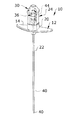
FIG. 1 is a perspective view of an embodiment of the present invention; -
FIG. 2 is a detail truncated perspective view of the present invention shown in an exemplary deployed position -
FIG. 3 is a detail truncated perspective view of the present invention shown in an exemplary recessed position; -
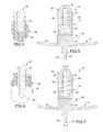
FIG. 4 is a section detail view illustrating a needle of the present invention entering tissue with an obturator recessed within the needle; -
FIG. 5 is a section detail view of the present invention taken along line 4-4 inFIG. 3 ; -
FIG. 6 is a section detail view illustrating a needle of the present invention entering epidural space with an obturator extending from the needle; -
FIG. 7 is a section detail view of the present invention taken along line 7-7 inFIG. 2 ; -
FIG. 8 is a section detail view of the present invention taken along line 8-8 inFIG. 7 ; -
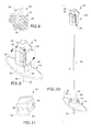
FIG. 9 is a detail perspective view of an embodiment of the present invention; -
FIG. 10 is an exploded view of an embodiment of the present invention; -
FIG. 11 is a bottom perspective view of an embodiment of the present invention; -
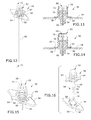
FIG. 12 is a perspective view of an embodiment of the present invention; -
FIG. 13 is a section detail view of the present invention taken along line 13-13 inFIG. 12 ; -
FIG. 14 is a section detail view of the present invention shown in a recessed configuration; -
FIG. 15 is a detail perspective view of an embodiment of the present invention; and -
FIG. 16 is a detail exploded view of an embodiment of the present invention. - The following detailed description is of the best currently contemplated modes of carrying out exemplary embodiments of the invention. The description is not to be taken in a limiting sense, but is made merely for the purpose of illustrating the general principles of the invention, since the scope of the invention is best defined by the appended claims.
- Referring to
FIGS. 1 through 11 , the present invention includes anapparatus 10 for locating and accessing anepidural space 48 within a patient. Theapparatus 10 includes ahandle 12 having a top end and a bottom end. Ahandle channel 16 is formed through thehandle 12 running from the top end to the bottom end. A proximal end of ahollow needle 22 extends from the bottom end of thehandle 12 and aligns with thehandle channel 16. A distal end of thehollow needle 22 is sharp and pointed. Anobturator 36 is disposed within thehollow needle 22 and thehandle channel 16. A distal end of theobturator 36 is rounded and blunt and extends from the distal end of thehollow needle 22. A proximal end of theobturator 36 extends beyond thehandle channel 16 at the top end of thehandle 12. - The
hollow needle 22 may be made of an elongated hollow tube of a rigid material, such as metal. As mentioned above, the distal end of thehollow needle 22 is sharp and pointed to easily pierce the skin andtissue 46 of the patient. In certain embodiments, the sharp and pointed end may be beveled. - The
obturator 36 may include anelongated shaft 40 that fits within thehollow needle 22. Theobturator 36 may be made of a soft flexible material, such as a polymer. The polymer may be plastic, biocompatible polyethylene, polytetrafluoroethylene, polycarbonate and the like. Theobturator 36 may further include astopper 42 at the proximal end. Thestopper 42 has larger diameter than thehandle channel 16 preventing the proximal end of theobturator 36 from entering thehandle channel 16 and thehollow needle 22. In certain embodiments, ashaft 38 upwardly extends from thestopper 42. - The
handle 12 of the present invention is used to manipulate thehollow needle 22 to accurately pierce a user'stissue 46. Thehandle 12 may include aplatform 14 having laterally extending arms. Atop protrusion 20 may extend upwardly from a top surface of theplatform 14. A bottom protrusion may extend downwardly from the bottom surface of theplatform 14. Thehandle channel 16 runs through thetop protrusion 20, theplatform 14 and the bottom protrusion. - The present invention may further include an
obturator housing 24. Thestopper 42 and theshaft 38 may be disposed within theobturator housing 24. Theobturator housing 24 may quickly connect and disconnect with thehandle 12 so that theobturator 36 may be quickly removed once theepidural space 40 is located. Theobturator housing 24 may include a top end and a bottom end. The bottom end includes ahousing channel 28 aligned with thehandle channel 16. Aninternal cavity 26 is formed in between the top end and the bottom end. The stopper andshaft 38 are disposed within theinternal cavity 26. Theobturator 36 runs through thehousing channel 28 and into thehandle channel 16. - The distal end of the
obturator 36 is biased to extend beyond the distal end of thehollow needle 22. When the distal end of theobturator 36 is pressed againsttissue 46, theobturator 36 recesses into thehollow needle 22 and thehollow needle 22 pierces thetissue 46. Once thehollow needle 22 reaches theepidural space 48, the distal end of theobturator 36 biases back to the extended position, indicating to the user that thehollow needle 22 has reached theepidural space 48. - The
apparatus 10 includes an automatic recessed and protruding mechanism. In such embodiments, aspring 44 is disposed around theshaft 38. Thespring 44 abuts against thestopper 42 and is disposed in between thestopper 42 and the top end of theobturator housing 24. Agap 32 is formed at the top end of theobturator housing 24 in which a top end of theshaft 38 fits within. Thespring 44 biases the distal end of theobturator 36 out of the distal end of thehollow needle 22. When the distal end of theobturator 36 presses against thetissue 46, theobturator 36 is pushed upwards so that theshaft 38 enters thegap 32 and the distal end recesses within thehollow needle 22. - In certain embodiments, a colored strip may be printed on the
shaft 38 and a portion of theobturator housing 24 is made of a transparent material. The colored strip is positioned to disappear when theshaft 38 is disposed within thegap 32. The colored strip is revealed through the transparent material when theshaft 38 biases out of thegap 32. Therefore, the user is easily able to determine when the end of the hollow needle has entered theepidural space 48. - As mentioned above, the
obturator housing 24 is attached to thehandle 12 by a quick connect and disconnect. In such embodiments, a lockingslot 18 may be formed on the top of thetop protrusion 20 of thehandle 12. Locking lets 34 may extend downwardly from the bottom end of theobturator housing 24. The user may engage thelegs 34 into the lockingslot 18 to attach theobturator housing 24 to thehandle 12 and disengage the lockinglegs 34 from the lockingslot 18 to remove theobturator housing 24 from thehandle 12. In certain embodiments, theslot 18 may include a first and second curved slots. The curved slots may include an enlarged entrance and a narrow engagement area having a lip. In such embodiments, the lockinglegs 34 may also include a lip. The lockinglegs 34 may enter the enlarged entrance and theobturator housing 24 may be rotated so that the lip of the lockinglegs 34 is disposed underneath the lip of the narrow engagement area of theslots 18, thereby locking theobturator housing 24 to thehandle 12. - A method of using the present invention may include the following steps: providing the
apparatus 10 mentioned above and grasping thehandle 14; piercingtissue 46 with the pointed tip of thehollow needle 22, wherein distal end ofobturator 36 recedes into thehollow needle 22 against the bias of thespring 44; reaching anepidural space 48 with thehollow needle 22, wherein the distal end of theobturator 36 is biased back to extend beyond the distal end of thehollow needle 12 due to a lack of tissue within theepidural space 48; detaching theobturator housing 24 from thehandle 14; removing theobturator 40 from thehollow needle 22; inserting a catheter through thehollow needle 22 and into theepidural space 48; and delivering a medication through the catheter and into theepidural space 48. - Referring to
FIGS. 12 through 16 , the present invention includes anapparatus 50 for locating and accessing an epidural space within a patient. Theapparatus 50 includes a handle 52 having a top end and a bottom end. Ahandle channel 56 is formed through the handle 52 running from the top end to the bottom end. A proximal end of ahollow needle 60 extends from the bottom end of the handle 52 and aligns with thehandle channel 56. A distal end of thehollow needle 60 is sharp and pointed. Anobturator 68 is disposed within thehollow needle 60 and thehandle channel 56. A distal end of theobturator 68 is rounded and blunt and extends from the distal end of thehollow needle 60. A proximal end of theobturator 68 extends beyond thehandle channel 56 at the top end of the handle 52. - The
obturator 68 includes astopper 72 at the proximal end. Thestopper 72 has larger diameter than thehandle channel 56 preventing the proximal end of theobturator 68 from entering thehandle channel 56 and thehollow needle 60. - The handle 52 of the present invention is used to manipulate the
hollow needle 60 to accurately pierce a user's tissue. The handle 52 may include aplatform 54 having laterally extending arms. A top protrusion may extend upwardly from a top surface of theplatform 54. A bottom protrusion may extend downwardly from the bottom surface of theplatform 54. Thehandle channel 16 runs through the top protrusion, theplatform 54 and the bottom protrusion. - The
apparatus 50 includes a manual recessed and protruding mechanism. In such embodiments, the present invention includes anaccordion sleeve 62 having a closed top end and an open bottom end leading into an internal cavity. The open bottom end is releasably attached to the top end of thehandle 54 so that thestopper 72 is disposed within the internal cavity. When in use, the user may gently press against the closed top end of theaccordion sleeve 62 and thereby gently press against thestopper 72 with their thumb or other finger. The user may pierce the tissue, which pushes theobturator 68 upwards into theneedle 60. Thestopper 72 is pushed against the user's thumb and theaccordion sleeve 62 extends to a stretched position. When the user reaches the epidural space, the user is easily able to push theobturator 68 back outwards beyond the distal end of thehollow needle 60, indicating to the user that the distal end of thehollow needle 60 is within the epidural space. - As mentioned above, the
accordion sleeve 62 is attached to thehandle 54 by a quick connect and disconnect. In such embodiments, a lockingclots 58 are formed on a top surface of theplatform 54. Laterally protrudingtabs 48 extend from the open bottom end of theaccordion sleeve 62. A user may simply place the open bottom end onto the top surface and rotate the protrudingtabs 48 to be underneath the lockingslots 58 to attach theaccordion sleeve 62 to thehandle 54. To disconnect theaccordion sleeve 62, theaccordion sleeve 62 may be rotated so that the protrudingtabs 48 are no longer disposed underneath the lockingslots 58 and theaccordion sleeve 62 may be removed from the handle 52. The open bottom end of theaccordion sleeve 62 may further includegrips 64 extending laterally so that user's may easily attach and detach theaccordion sleeve 62 to thehandle 54. - It should be understood, of course, that the foregoing relates to exemplary embodiments of the invention and that modifications may be made without departing from the spirit and scope of the invention as set forth in the following claims.
Claims (10)
Priority Applications (1)
| Application Number | Priority Date | Filing Date | Title |
|---|---|---|---|
| US15/638,777 US10322265B2 (en) | 2016-10-12 | 2017-06-30 | Apparatus and method for accessing an epidural space |
Applications Claiming Priority (2)
| Application Number | Priority Date | Filing Date | Title |
|---|---|---|---|
| US201662407069P | 2016-10-12 | 2016-10-12 | |
| US15/638,777 US10322265B2 (en) | 2016-10-12 | 2017-06-30 | Apparatus and method for accessing an epidural space |
Publications (2)
| Publication Number | Publication Date |
|---|---|
| US20180098786A1 true US20180098786A1 (en) | 2018-04-12 |
| US10322265B2 US10322265B2 (en) | 2019-06-18 |
Family
ID=61829831
Family Applications (1)
| Application Number | Title | Priority Date | Filing Date |
|---|---|---|---|
| US15/638,777 Active US10322265B2 (en) | 2016-10-12 | 2017-06-30 | Apparatus and method for accessing an epidural space |
Country Status (1)
| Country | Link |
|---|---|
| US (1) | US10322265B2 (en) |
Citations (4)
| Publication number | Priority date | Publication date | Assignee | Title |
|---|---|---|---|---|
| US4958901A (en) * | 1987-07-13 | 1990-09-25 | Neurodelivery Technology, Inc. | Method for making a multi-lumen epidural-spinal needle and tip and stock configuration for the same |
| US5163901A (en) * | 1990-05-28 | 1992-11-17 | Joseph Eldor | Device for combined spinal and epidural anesthesia |
| US5637096A (en) * | 1990-12-27 | 1997-06-10 | Yoon; Inbae | Safety needle |
| US20030114797A1 (en) * | 2001-12-17 | 2003-06-19 | Vaillancourt Vincent L. | Safety needle with collapsible sheath |
-
2017
- 2017-06-30 US US15/638,777 patent/US10322265B2/en active Active
Patent Citations (4)
| Publication number | Priority date | Publication date | Assignee | Title |
|---|---|---|---|---|
| US4958901A (en) * | 1987-07-13 | 1990-09-25 | Neurodelivery Technology, Inc. | Method for making a multi-lumen epidural-spinal needle and tip and stock configuration for the same |
| US5163901A (en) * | 1990-05-28 | 1992-11-17 | Joseph Eldor | Device for combined spinal and epidural anesthesia |
| US5637096A (en) * | 1990-12-27 | 1997-06-10 | Yoon; Inbae | Safety needle |
| US20030114797A1 (en) * | 2001-12-17 | 2003-06-19 | Vaillancourt Vincent L. | Safety needle with collapsible sheath |
Also Published As
| Publication number | Publication date |
|---|---|
| US10322265B2 (en) | 2019-06-18 |
Similar Documents
| Publication | Publication Date | Title |
|---|---|---|
| US20260091206A1 (en) | Wire introduction device | |
| JP2739840B2 (en) | Needle assembly with one-handed needle barrier | |
| US3459183A (en) | Catheter placement unit with anesthetic | |
| US5817052A (en) | Apparatus for intraosseous infusion or aspiration | |
| US8628497B2 (en) | Safety catheter | |
| EP2600923B1 (en) | Apparatus and method for safely inserting an introducer needle into epidural space | |
| US7762993B2 (en) | Catheter syringe conveyor with a needle guard housing | |
| US6391014B1 (en) | Strong diaphragm/safe needle/converting device combinations and their individual components | |
| US20030083624A1 (en) | Intravascular administration set needle safety device | |
| US20150352318A1 (en) | Ultrasound assisted catheter placement system | |
| US20150119852A1 (en) | Method and apparatus for introducing an intraveneous catheter | |
| US12042169B2 (en) | Double needle system to facilitate placing abdominal wall nerve blocks or infusion catheters | |
| JP2004000576A (en) | Non-patient needle device and blood collection set | |
| JPH0857052A (en) | Device for adjusting extension length of compound spine needle-hard hemp needle and method for adjusting the same | |
| JP2003534877A (en) | Tubing for use with medical syringes | |
| CN110124153B (en) | Syringe assembly | |
| US20210315776A1 (en) | Syringe assembly | |
| US8333734B2 (en) | Fenestrated peripheral nerve block needle and method for using the same | |
| US12251543B2 (en) | Variable length injection syringe | |
| US20080312677A1 (en) | Soft tissue tunneling device | |
| US9345833B1 (en) | Dental instrument | |
| US10322265B2 (en) | Apparatus and method for accessing an epidural space | |
| US20220110658A1 (en) | Bone-penetrating manual driver and stabilizer assembly for intraosseous access | |
| KR20230147637A (en) | Intravascular catheters and methods of their use | |
| US10569027B2 (en) | Epidural needle assembly |
Legal Events
| Date | Code | Title | Description |
|---|---|---|---|
| STPP | Information on status: patent application and granting procedure in general |
Free format text: NOTICE OF ALLOWANCE MAILED -- APPLICATION RECEIVED IN OFFICE OF PUBLICATIONS |
|
| STCF | Information on status: patent grant |
Free format text: PATENTED CASE |
|
| FEPP | Fee payment procedure |
Free format text: MAINTENANCE FEE REMINDER MAILED (ORIGINAL EVENT CODE: REM.); ENTITY STATUS OF PATENT OWNER: SMALL ENTITY |
|
| FEPP | Fee payment procedure |
Free format text: SURCHARGE FOR LATE PAYMENT, SMALL ENTITY (ORIGINAL EVENT CODE: M2554); ENTITY STATUS OF PATENT OWNER: SMALL ENTITY |
|
| MAFP | Maintenance fee payment |
Free format text: PAYMENT OF MAINTENANCE FEE, 4TH YR, SMALL ENTITY (ORIGINAL EVENT CODE: M2551); ENTITY STATUS OF PATENT OWNER: SMALL ENTITY Year of fee payment: 4 |