US20180098784A1 - Treatment method - Google Patents
Treatment method Download PDFInfo
- Publication number
- US20180098784A1 US20180098784A1 US15/291,805 US201615291805A US2018098784A1 US 20180098784 A1 US20180098784 A1 US 20180098784A1 US 201615291805 A US201615291805 A US 201615291805A US 2018098784 A1 US2018098784 A1 US 2018098784A1
- Authority
- US
- United States
- Prior art keywords
- pressing force
- amplitude
- pressing
- cartilage
- cutting
- Prior art date
- Legal status (The legal status is an assumption and is not a legal conclusion. Google has not performed a legal analysis and makes no representation as to the accuracy of the status listed.)
- Granted
Links
- 238000000034 method Methods 0.000 title claims abstract description 15
- 210000000845 cartilage Anatomy 0.000 claims abstract description 36
- 210000000988 bone and bone Anatomy 0.000 description 39
- 239000000523 sample Substances 0.000 description 26
- 230000001054 cortical effect Effects 0.000 description 23
- 210000001519 tissue Anatomy 0.000 description 21
- 238000001514 detection method Methods 0.000 description 17
- 230000008859 change Effects 0.000 description 10
- 230000007423 decrease Effects 0.000 description 8
- 238000002474 experimental method Methods 0.000 description 7
- 238000010586 diagram Methods 0.000 description 6
- 210000000629 knee joint Anatomy 0.000 description 4
- 238000012986 modification Methods 0.000 description 3
- 230000004048 modification Effects 0.000 description 3
- 238000001356 surgical procedure Methods 0.000 description 3
- 238000005516 engineering process Methods 0.000 description 2
- 230000006870 function Effects 0.000 description 2
- 230000001133 acceleration Effects 0.000 description 1
- 238000006243 chemical reaction Methods 0.000 description 1
- 238000004090 dissolution Methods 0.000 description 1
- 230000005484 gravity Effects 0.000 description 1
- 230000002401 inhibitory effect Effects 0.000 description 1
- 210000001503 joint Anatomy 0.000 description 1
- 239000004973 liquid crystal related substance Substances 0.000 description 1
- 239000007769 metal material Substances 0.000 description 1
- 238000010248 power generation Methods 0.000 description 1
- 230000009467 reduction Effects 0.000 description 1
- 230000004044 response Effects 0.000 description 1
- 210000000323 shoulder joint Anatomy 0.000 description 1
Images


Classifications
-
- A—HUMAN NECESSITIES
- A61—MEDICAL OR VETERINARY SCIENCE; HYGIENE
- A61B—DIAGNOSIS; SURGERY; IDENTIFICATION
- A61B17/00—Surgical instruments, devices or methods
- A61B17/32—Surgical cutting instruments
- A61B17/320068—Surgical cutting instruments using mechanical vibrations, e.g. ultrasonic
-
- A—HUMAN NECESSITIES
- A61—MEDICAL OR VETERINARY SCIENCE; HYGIENE
- A61B—DIAGNOSIS; SURGERY; IDENTIFICATION
- A61B17/00—Surgical instruments, devices or methods
- A61B17/32—Surgical cutting instruments
- A61B17/320016—Endoscopic cutting instruments, e.g. arthroscopes, resectoscopes
-
- A—HUMAN NECESSITIES
- A61—MEDICAL OR VETERINARY SCIENCE; HYGIENE
- A61B—DIAGNOSIS; SURGERY; IDENTIFICATION
- A61B17/00—Surgical instruments, devices or methods
- A61B2017/00017—Electrical control of surgical instruments
- A61B2017/00022—Sensing or detecting at the treatment site
- A61B2017/00026—Conductivity or impedance, e.g. of tissue
- A61B2017/0003—Conductivity or impedance, e.g. of tissue of parts of the instruments
-
- A—HUMAN NECESSITIES
- A61—MEDICAL OR VETERINARY SCIENCE; HYGIENE
- A61B—DIAGNOSIS; SURGERY; IDENTIFICATION
- A61B17/00—Surgical instruments, devices or methods
- A61B2017/00017—Electrical control of surgical instruments
- A61B2017/00137—Details of operation mode
- A61B2017/00154—Details of operation mode pulsed
- A61B2017/00181—Means for setting or varying the pulse energy
- A61B2017/00185—Means for setting or varying the pulse height
-
- A—HUMAN NECESSITIES
- A61—MEDICAL OR VETERINARY SCIENCE; HYGIENE
- A61B—DIAGNOSIS; SURGERY; IDENTIFICATION
- A61B17/00—Surgical instruments, devices or methods
- A61B2017/00973—Surgical instruments, devices or methods pedal-operated
- A61B2017/00977—Surgical instruments, devices or methods pedal-operated the depression depth determining the power rate
-
- A—HUMAN NECESSITIES
- A61—MEDICAL OR VETERINARY SCIENCE; HYGIENE
- A61B—DIAGNOSIS; SURGERY; IDENTIFICATION
- A61B90/00—Instruments, implements or accessories specially adapted for surgery or diagnosis and not covered by any of the groups A61B1/00 - A61B50/00, e.g. for luxation treatment or for protecting wound edges
- A61B90/06—Measuring instruments not otherwise provided for
- A61B2090/064—Measuring instruments not otherwise provided for for measuring force, pressure or mechanical tension
- A61B2090/065—Measuring instruments not otherwise provided for for measuring force, pressure or mechanical tension for measuring contact or contact pressure
-
- A—HUMAN NECESSITIES
- A61—MEDICAL OR VETERINARY SCIENCE; HYGIENE
- A61B—DIAGNOSIS; SURGERY; IDENTIFICATION
- A61B90/00—Instruments, implements or accessories specially adapted for surgery or diagnosis and not covered by any of the groups A61B1/00 - A61B50/00, e.g. for luxation treatment or for protecting wound edges
- A61B90/08—Accessories or related features not otherwise provided for
- A61B2090/0807—Indication means
Definitions
- the present invention relates to a treatment method.
- An ultrasonic surgical instrument is known as one of the treatment tools for treating body tissue.
- the ultrasonic surgical instrument is configured to press a probe that is ultrasonically vibrating against body tissue, which is a subject, so as to treat the body tissue.
- body tissue which is a subject
- it is important to perform pressing with an appropriate pressing force. Therefore, for example, the ultrasonic surgical instrument proposed in Jpn. Pat. Appln. KOKAI Publication No. 2003-235862 is configured to use a spring which mechanically changes in accordance with a pressing force of a probe brought into contact with body tissue and detection means for detecting the change of the spring so as to detect the pressing force, and to generate ultrasonic vibration when the detected pressing force falls within a desired range.
- a treatment method of one aspect of the present invention is a treatment method for cutting cartilage of a human body by an ultrasonic device including a cutting section that ultrasonically vibrates, the treatment method comprising: cutting the cartilage with a product of an amplitude of the cutting section and a pressing force for pressing the cutting section against the cartilage being 100 (N ⁇ m) or larger.
- FIG. 1 shows a configuration of an ultrasonic device as one example of an ultrasonic surgical instrument according to each embodiment
- FIG. 2 is a block diagram showing a main configuration of an ultrasonic device in a first embodiment
- FIG. 3 is a block diagram showing a configuration of a control circuit in the first embodiment
- FIG. 4 is a flowchart showing an operation of the ultrasonic device
- FIG. 5 is a graph showing a result of an experiment for measuring a change in the cut amount in the case where the amplitude or the pressing force against cortical bone is changed;
- FIG. 6A is a graph showing a result of an experiment for measuring changes in the cut amount in the case where the amplitude or pressing force against cartilage is changed;
- FIG. 6B is a graph in which the lateral axis indicates (pressing force)*(amplitude) and the vertical axis Indicates the cut amount based on the result of FIG. 6A ;
- FIG. 7 is a block diagram showing a configuration of a control circuit in a second embodiment.
- FIG. 8 is a flowchart showing a flow of treatment using the ultrasonic device.
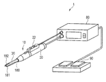
- FIG. 1 shows a configuration of an ultrasonic device 1 as one example of an ultrasonic surgical instrument according to each embodiment of the present invention.
- the ultrasonic device 1 includes: a treatment tool 10 for treating body tissue by ultrasonic waves; a power supply apparatus 80 that supplies the treatment tool 10 with drive power; and a foot switch 90 .
- the ultrasonic device 1 has a cortical bone/cancellous bone cutting mode, which is a mode suitable for cutting hard bone such as cortical bone, and a cartilage cutting mode, which is a mode suitable for cutting cartilage.
- the ultrasonic device 1 may also be used for a treatment other than cutting of bone.
- the treatment tool 10 includes: a hand piece 20 ; a probe 180 protruding from the hand piece 20 ; and a thin and long sheath 30 formed around the probe 180 .
- the probe 180 side in the treatment tool 10 is called a “distal end side” of the treatment tool 10
- the hand piece 20 side is called a “proximal end side.”
- the hand piece 20 includes therein an ultrasonic transducer.
- the ultrasonic transducer ultrasonically vibrates in accordance with the drive power from the power supply apparatus 80 .
- the hand piece 20 conveys ultrasonic vibration generated at the ultrasonic transducer to the probe 180 .
- the probe 180 is connected to the ultrasonic transducer and vibrates in accordance with the vibration of the ultrasonic transducer.
- the distal end of the sheath 30 is shaped like a half round cylinder, and a cutting section 181 provided at the distal end of the probe 180 is exposed from the portion shaped like a half round cylinder.
- a cold knife 182 is formed at the distal end of the sheath 30 .
- the cold knife 182 is made of a corrosive-resistant metallic material, and is used to facilitate cutting of body tissue.
- the cold knife 182 is not necessarily provided.
- the hand piece 20 includes an input section 22 .
- the input section 22 is a section for inputting instructions to drive the ultrasonic transducer.
- the input section 22 may include a plurality of switches for switching between the cortical bone/cancellous bone cutting mode and the cartilage cutting mode.
- the input section 22 is connected to the power supply apparatus 80 .
- the ultrasonic transducer in the hand piece 20 is connected to the power supply apparatus 80 .
- the power supply apparatus 80 detects an input to the input section 22 , and supplies the ultrasonic transducer with drive power corresponding to the input.
- the foot switch 90 has the same function as that of the input section 22 provided in the hand piece 20 . Namely, like the input section 22 , the foot switch 90 may include a plurality of switches for switching between the cortical bone/cancellous bone cutting mode and the cartilage cutting mode. Upon detection of an input to the foot switch 90 , the power supply apparatus 80 supplies the ultrasonic transducer with drive power corresponding to the input. At least one of the input section 22 and the foot switch 90 needs to be provided.
- a user When performing treatment, a user holds the hand piece 20 , and brings the cutting section 181 provided in the probe 180 that ultrasonically vibrates into contact with body tissue to be treated. At this time, the user operates the input section 22 or the foot switch 90 to vibrate the ultrasonic transducer. The vibration generated at the ultrasonic transducer is conveyed to the probe 180 . By bringing the cutting section 181 of the vibrating probe 180 into contact with body tissue, the body tissue is subjected to treatment, such as cutting.
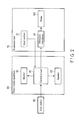
- FIG. 2 is a block diagram showing a main configuration of the ultrasonic device 1 in the first embodiment of the present invention.
- the same elements as those in FIG. 1 will be assigned the same reference numerals as those in FIG. 1 to omit their descriptions.
- the power supply apparatus 80 includes: a control circuit 81 ; a monitor 82 ; and a speaker 83 .
- the control circuit 81 is configured as an IC including, for example, an output generation circuit that generates drive power of the ultrasonic transducer 24 , and a circuit that reports to an operator whether the operator's pressing of the probe 180 is appropriate.
- the control circuit 81 controls the drive power of the ultrasonic transducer 24 in accordance with the input from the input section 22 or the foot switch 90 .
- the control circuit 81 detects an operator's pressing force of the probe 180 against body tissue, which is a subject, and reports to the operator whether the current pressing of the probe 180 is appropriate in accordance with the detected pressing force, by using, for example, a monitor 82 , a speaker 83 , or both.
- the monitor 82 is, for example, a liquid crystal display and displays various types of images based on control by the control circuit 81 .
- the speaker 83 emits various types of voices based on control by the control circuit 81 .
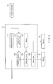
- FIG. 3 is a block diagram showing a configuration of the control circuit 81 in the first embodiment.
- the control circuit 81 includes an output generation circuit 811 , a voltage current detection circuit 812 , an impedance detection circuit 813 , a comparison circuit 814 , a memory 815 , and a report circuit 816 .
- the output generation circuit 811 includes a power generation circuit, such as a regulator. In response to an operation of the input section 22 or the foot switch 90 , the output generation circuit 811 generates drive power of the ultrasonic transducer 24 so that the ultrasonic transducer 24 vibrates with an amplitude corresponding to the designated value from the input section 22 or the foot switch 90 .
- the amplitude in the cartilage cutting mode is set higher than that in the cortical bone/cancellous bone cutting mode. This is because cutting is performed mainly by friction heat generated by ultrasonic vibration in the cartilage cutting mode.
- the quantity of heat Q[J] generated when an object having a mass m[kg] slides on a rough horizontal surface having a kinetic friction coefficient ⁇ ° by s[m] is expressed by the following equation (Equation 1), where the acceleration of gravity is g(m/s 2 ):
- the magnitude of the pressing force (N) of the probe 180 is considered to correspond to “mg” in the equation.
- “s” corresponds to the amplitude of vertical vibration of the ultrasonic probe. Therefore, if the pressing force is constant, the cut amount of cartilage increases as the amplitude of the probe 180 increases.
- the amplitude of ultrasonic vibration is set to be as large as possible to improve cutting efficiency.
- cutting is performed by an impact caused by ultrasonic vibration, rather than friction heat caused by ultrasonic vibration.
- the pressing force is the normal component of the force relative to the rough surface; however, the pressing force may be regarded as, for example, a force of the state having an angle relative to the normal.
- the voltage current detection circuit 812 detects each of the output voltage and output current of the output generation circuit 811 .
- the impedance detection circuit 813 calculates an impedance of the ultrasonic transducer 24 from the ratio between the output voltage and output current detected at the voltage current detection circuit 812 .
- the impedance of the ultrasonic transducer 24 may change depending on the pressing force of the probe 180 against body tissue. Therefore, the impedance detection circuit 813 functions as a detection circuit (sensor) that indirectly detects a pressing force of the probe 180 by detecting the impedance of the ultrasonic transducer 24 .
- the impedance of the ultrasonic transducer 24 may change depending on the type or temperature of body tissue against which the ultrasonic transducer 24 is pressed.
- the comparison circuit 814 converts the value of the impedance detected at the impedance detection circuit 813 into a value of a pressing force.
- the comparison circuit 814 compares the value of the pressing force obtained by conversion with a pressing force range stored in the memory 815 .
- the comparison circuit 814 then instructs the report circuit 816 to make a report corresponding to the comparison result of the pressing force.
- the memory 815 stores the pressing force range. If the pressing force decreases, the cut amount decreases, which results in a longer surgery time. If the pressing force increases, the cut amount increases, but heat intrusion to surrounding tissue also increases. Accordingly, the pressing force range is determined in accordance with the balance between the cut amount and heat intrusion. Different pressing force ranges are used for the cortical bone/cancellous bone cutting mode and the cartilage cutting mode. The details will be described later.
- the memory 815 stores a table for converting the value of the impedance detected at the impedance detection circuit 813 into a value of a pressing force. This table is obtained by, for example, actually measuring the change in the impedance made when variously changing the pressing force of the probe 180 while keeping the amplitude of the probe 180 at a constant value.
- the report circuit 816 makes a report to an operator by using the monitor 82 and the speaker 83 in accordance with instructions from the comparison circuit 814 .
- the report tells whether an operator's pressing of the probe 180 is appropriate, strong, or weak.
- the report may instruct a user to weaken pressing when the pressing is strong, and to strengthen pressing when the pressing is weak.
- the report may be made by displaying, for example, a gage indicating a pressing force.
- FIG. 4 is a flowchart showing an operation of the ultrasonic device 1 .
- the processing shown in FIG. 4 is started when, for example, the ultrasonic device 1 is turned on, and the input section 22 or the foot switch 90 is operated.
- step S 1 the output generation circuit 811 generates drive power for driving the ultrasonic transducer 24 .
- the output generation circuit 811 When the input section 22 or the foot switch 90 designates the cartilage cutting mode, the output generation circuit 811 generates drive power to generate ultrasonic vibration with an amplitude corresponding to a designated value set in advance for the cartilage cutting mode.
- the output generation circuit 811 when the input section 22 or the foot switch 90 designates the cortical bone/cancellous bone cutting mode, the output generation circuit 811 generates drive power to generate ultrasonic vibration with an amplitude corresponding to a designated value set in advance for the cortical bone/cancellous bone cutting mode.
- the output generation circuit 811 may be configured to perform feedback control on drive power. In this case, for example, the output current of the output generation circuit 811 detected at the voltage current detection circuit 812 is returned to the output generation circuit 811 .
- the output generation circuit 811 controls the output voltage so that the returned output current matches the designated value.
- step S 2 the impedance detection circuit 813 calculates an impedance of the ultrasonic transducer 24 from the ratio between the output voltage and output current detected by the voltage current detection circuit 812 .
- step S 3 the comparison circuit 814 converts the value of the impedance calculated at the impedance detection circuit 813 into a value of a pressing force in accordance with the table stored in advance in the memory 815 .
- step S 4 the comparison circuit 814 compares the value of the current pressing force obtained from the value of the impedance with the pressing force range stored in advance in the memory 815 . Based on the comparison result, the comparison circuit 814 determines whether the operator's pressing force of the probe 180 is appropriate. For example, if the value of the current pressing force falls within the pressing force range stored in advance in the memory 815 , the pressing force is determined as appropriate.
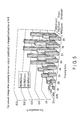
- FIG. 5 is a graph showing a result of an experiment for measuring a change in the cut amount in the case where the amplitude or pressing force against cortical bone is changed.
- the cut amount volume of the cut cortical bone
- an average value of the cut amounts at the six points is shown as the cut amount.
- the value of the amplitude is expressed by a percentage relative to the maximum amplitude (81 ⁇ m) of the jig used in the experiment.
- the pressing force range in the cortical bone/cancellous bone cutting mode is 3(N)-5(N) when the amplitude is 40% (23 ⁇ m), 2(N)-6(N) when the amplitude is 70% (57 ⁇ m), and 1(N)-7(N) when the amplitude is 100% (81 ⁇ m).
- Those values are stored in the memory 815 .
- FIG. 6A is a graph showing a result of an experiment for measuring a change in the cut amount in the case where the amplitude or pressing force against cartilage is changed.
- the value of the amplitude is expressed by a percentage relative to the maximum amplitude (81 ⁇ m) of the jig used in the experiment.
- FIG. 6A is a graph in which the lateral axis indicates (pressing force)*(amplitude) and the vertical axis indicates the cut amount based on the result of FIG. 6A .
- the pressing force range in the cartilage cutting mode are values which allow the value of (pressing force)*(amplitude) to fall within the range of 100 [N ⁇ m]-300 [N ⁇ m]. Those values are stored in the memory 815 .
- the comparison circuit 184 compares the pressing force range fixed by the relationship shown in FIG. 5 or 6B with the current pressing force. If the pressing force is determined as appropriate in step S 4 , the processing moves to step S 5 . If the pressing force is determined as inappropriate in step S 4 , the processing moves to step S 6 .
- step S 5 the comparison circuit 814 notifies the report circuit 816 that the pressing force is appropriate.
- the report circuit 816 reports to an operator that the operator's current pressing force is appropriate by using the monitor 82 and the speaker 83 .
- the processing moves to step S 9 .
- the report is made by displaying a message, such as “pressing is appropriate”, on the monitor 82 , or emitting a voice from the speaker 83 , or both.
- step S 6 the comparison circuit 814 determines whether operator's pressing force of the probe 180 is strong. For example, if the value of the current pressing force exceeds the pressing force range stored in advance in the memory 815 , the pressing force is determined as strong. In contrast, if the value of the current pressing force is below the pressing force range stored in advance in the memory 815 , the pressing force is determined as weak. If the pressing force is determined as strong in step S 6 , the processing moves to step S 7 . If the pressing force is determined as weak in step S 6 , the processing moves to step S 8 .
- step S 7 the comparison circuit 814 notifies the report circuit 816 that the pressing force is strong.
- the report circuit 816 reports to an operator that the operator's pressing should be weakened by using the monitor 82 and the speaker 83 .
- the processing moves to step S 9 .
- the report is made by displaying a message such as “press more weakly” on the monitor 82 , or emitting a voice from the speaker 83 , or both.
- step S 8 the comparison circuit 814 notifies the report circuit 816 that the pressing force is weak.
- the report circuit 816 reports to an operator that the operator's pressing should be strengthened by using the monitor 82 and the speaker 83 .
- the processing moves to step S 9 .
- the report is made by displaying a message such as “press more strongly” on the monitor 82 , or emitting a voice from the speaker 83 , or both.
- step S 9 the output generation circuit 811 determines whether to finish the processing. For example, the processing is determined to be finished when the ultrasonic device 1 is turned off, or when the operation of the input section 22 or the foot switch 90 is canceled. When the processing is determined to be finished in step S 9 , the processing in FIG. 4 ends. If the pressing force is determined not to be finished in Step S 9 , the processing returns to step S 1 .
- an operator's pressing force of the probe 180 against body tissue is compared with a predetermined pressing force range, and whether or not the operator's pressing is appropriate is reported based on the comparison result.
- the operator can thereby perform treatment with an appropriate pressing force.
- different pressing force ranges are used for the cortical bone/cancellous bone cutting mode and the cartilage cutting mode in the present embodiment. This allows the operator to perform pressing based on only the report from the ultrasonic device 1 without regard to the difference between the cortical bone/cancellous bone cutting mode and the cartilage cutting mode.
- the steps in the processing of FIG. 4 are performed by using a “circuit,” but may be performed by software.
- the current pressing force is compared with a range, and a report is made for the operator in accordance with the comparison result.
- the current pressing force is compared with a pressing force range, and feedback control is performed on the amplitude of an ultrasonic transducer 24 in accordance with the comparison result.
- FIG. 7 is a block diagram showing a configuration of a control circuit 81 in the second embodiment.
- the control circuit 81 includes an output generation circuit 811 , a voltage current detection circuit 812 , an impedance detection circuit 813 , a comparison circuit 814 , and a memory 815 .
- the control circuit 81 in the second embodiment is configured to return the output of the comparison circuit 814 to the output generation circuit 811 .
- the output generation circuit 811 in the second embodiment controls drive power so that ultrasonic vibrations of different amplitudes are generated in the cortical bone/cancellous bone cutting mode and the cartilage cutting mode.
- the output generation circuit 811 in the second embodiment performs control to increase or decrease the amplitude in accordance with the difference between the value of a current pressing force and the upper limit or lower limit of the pressing force range stored in advance.
- the output generation circuit 811 performs control to increase or decrease the amplitude so that the current pressing value takes a value satisfying the condition that (pressing force)*(amplitude) falls within the range of 100 [N ⁇ m]-300 [N ⁇ m].
- the output generation circuit 811 performs control to increase or decrease the amplitude in accordance with the value of the current pressing force. For example, when the pressing force is 3N or weaker, the output generation circuit 811 performs control to increase the amplitude to inhibit reduction of the cut amount. When the pressing force is 5N or stronger, the output generation circuit 811 performs control to decrease the amplitude as a safety measure for inhibiting generation of heat.
- feedback control of amplitude is performed in accordance with the difference between the value of the current pressing force and the upper limit or lower limit of the range of the pressing force stored in advance in the memory 815 . Therefore, an operator can perform treatment without changing the pressing strength.
- FIG. 8 is a flowchart showing a flow of treatment using the ultrasonic device 1 .
- FIG. 8 shows a flow of cutting treatment of degenerating cartilage in a knee joint.
- the flow of FIG. 8 is applicable to treatment of not only the knee joint, but also other joints, such as a shoulder joint.
- a doctor uses a trocar to form a port to allow a treatment tool and an arthroscope to be inserted to a position of body tissue to be treated (here, degenerating cartilage in a knee joint).
- step S 102 the doctor inserts an arthroscope and a treatment tool 10 of an ultrasonic device 1 through the port for the arthroscope.
- step S 103 the doctor brings the cutting section 181 of the ultrasonic device 1 into contact with the degenerating cartilage to be treated while viewing an image of the inside of the knee joint displayed on a monitor via the arthroscope.
- step S 104 the doctor operates, for example, the input section 22 to set the ultrasonic device 1 in a cartilage dissolution mode, and performs cutting while pressing the treatment tool against the degenerating cartilage and confirming how much the treatment tool is pressed.
- a message indicating strong pressing such as “pressing is too strong” is displayed on the monitor 82 , for example, and the doctor can continue treatment with weaker pressing while viewing the monitor 82 without stopping the manipulation.
- a message such as “pressing is appropriate” is displayed on the monitor 82 , and the doctor performs treatment while keeping the current pressing by viewing the monitor 82 .
- a message indicating weak pressing such as “pressing is too weak” is displayed on the monitor 82 , for example, and the doctor can continue treatment with stronger pressing while viewing the monitor 82 without stopping the manipulation.
- a message such as “pressing is appropriate” is displayed on the monitor 82 , and the doctor performs treatment while keeping the current pressing by viewing the monitor 82 .
- a doctor can intuitively know whether the cut amount is small due to too weak pressing or treatment is proceeding with heat intrusion to surrounding tissue due to too strong pressing by a voice or a display of a monitor, and thus can perform efficient and safe surgery with little heat intrusion without stopping the manipulation.
- the doctor can proceed with surgery without regard to the pressing force.
- the pressing force is detected based on the impedance of the ultrasonic transducer.
- the pressing force need not be detected based on the impedance of the ultrasonic transducer.
- the pressing force may be detected by a sensor that directly detects a force, such as a distortion gage.
- the pressing force may be detected based on a change in the resonance frequency of the probe.
- the pressing force may also be detected based on temperature.
Landscapes
- Health & Medical Sciences (AREA)
- Surgery (AREA)
- Life Sciences & Earth Sciences (AREA)
- Engineering & Computer Science (AREA)
- Heart & Thoracic Surgery (AREA)
- Nuclear Medicine, Radiotherapy & Molecular Imaging (AREA)
- Biomedical Technology (AREA)
- Medical Informatics (AREA)
- Molecular Biology (AREA)
- Animal Behavior & Ethology (AREA)
- General Health & Medical Sciences (AREA)
- Public Health (AREA)
- Veterinary Medicine (AREA)
- Mechanical Engineering (AREA)
- Dentistry (AREA)
- Surgical Instruments (AREA)
- Orthopedic Medicine & Surgery (AREA)
Abstract
Description
- The present invention relates to a treatment method.
- An ultrasonic surgical instrument is known as one of the treatment tools for treating body tissue. The ultrasonic surgical instrument is configured to press a probe that is ultrasonically vibrating against body tissue, which is a subject, so as to treat the body tissue. For efficient treatment, it is important to perform pressing with an appropriate pressing force. Therefore, for example, the ultrasonic surgical instrument proposed in Jpn. Pat. Appln. KOKAI Publication No. 2003-235862 is configured to use a spring which mechanically changes in accordance with a pressing force of a probe brought into contact with body tissue and detection means for detecting the change of the spring so as to detect the pressing force, and to generate ultrasonic vibration when the detected pressing force falls within a desired range.
- A treatment method of one aspect of the present invention is a treatment method for cutting cartilage of a human body by an ultrasonic device including a cutting section that ultrasonically vibrates, the treatment method comprising: cutting the cartilage with a product of an amplitude of the cutting section and a pressing force for pressing the cutting section against the cartilage being 100 (N·μm) or larger.
- Advantages of the invention will be set forth in the description which follows, and in part will be obvious from the description, or may be learned by practice of the invention. The advantages of the invention may be realized and obtained by means of the instrumentalities and combinations particularly pointed out hereinafter.
- The accompanying drawings, which are incorporated in and constitute a part of the specification, illustrate embodiments of the invention, and together with the general description given above and the detailed description of the embodiments given below, serve to explain the principles of the invention.
-
FIG. 1 shows a configuration of an ultrasonic device as one example of an ultrasonic surgical instrument according to each embodiment; -
FIG. 2 is a block diagram showing a main configuration of an ultrasonic device in a first embodiment; -
FIG. 3 is a block diagram showing a configuration of a control circuit in the first embodiment; -
FIG. 4 is a flowchart showing an operation of the ultrasonic device; -
FIG. 5 is a graph showing a result of an experiment for measuring a change in the cut amount in the case where the amplitude or the pressing force against cortical bone is changed; -
FIG. 6A is a graph showing a result of an experiment for measuring changes in the cut amount in the case where the amplitude or pressing force against cartilage is changed; -
FIG. 6B is a graph in which the lateral axis indicates (pressing force)*(amplitude) and the vertical axis Indicates the cut amount based on the result ofFIG. 6A ; -
FIG. 7 is a block diagram showing a configuration of a control circuit in a second embodiment; and -
FIG. 8 is a flowchart showing a flow of treatment using the ultrasonic device. - Hereinafter, embodiments of the present invention will be described with reference to the drawings.
- The first embodiment of the present invention will be described.
FIG. 1 shows a configuration of anultrasonic device 1 as one example of an ultrasonic surgical instrument according to each embodiment of the present invention. Theultrasonic device 1 includes: atreatment tool 10 for treating body tissue by ultrasonic waves; apower supply apparatus 80 that supplies thetreatment tool 10 with drive power; and afoot switch 90. Theultrasonic device 1 has a cortical bone/cancellous bone cutting mode, which is a mode suitable for cutting hard bone such as cortical bone, and a cartilage cutting mode, which is a mode suitable for cutting cartilage. However, theultrasonic device 1 may also be used for a treatment other than cutting of bone. - The
treatment tool 10 includes: ahand piece 20; aprobe 180 protruding from thehand piece 20; and a thin andlong sheath 30 formed around theprobe 180. In the following descriptions, theprobe 180 side in thetreatment tool 10 is called a “distal end side” of thetreatment tool 10, and thehand piece 20 side is called a “proximal end side.” - The
hand piece 20 includes therein an ultrasonic transducer. The ultrasonic transducer ultrasonically vibrates in accordance with the drive power from thepower supply apparatus 80. Thehand piece 20 conveys ultrasonic vibration generated at the ultrasonic transducer to theprobe 180. Theprobe 180 is connected to the ultrasonic transducer and vibrates in accordance with the vibration of the ultrasonic transducer. - The distal end of the
sheath 30 is shaped like a half round cylinder, and acutting section 181 provided at the distal end of theprobe 180 is exposed from the portion shaped like a half round cylinder. In addition, for example, acold knife 182 is formed at the distal end of thesheath 30. Thecold knife 182 is made of a corrosive-resistant metallic material, and is used to facilitate cutting of body tissue. Thecold knife 182 is not necessarily provided. - The
hand piece 20 includes aninput section 22. Theinput section 22 is a section for inputting instructions to drive the ultrasonic transducer. Theinput section 22 may include a plurality of switches for switching between the cortical bone/cancellous bone cutting mode and the cartilage cutting mode. Theinput section 22 is connected to thepower supply apparatus 80. The ultrasonic transducer in thehand piece 20 is connected to thepower supply apparatus 80. Thepower supply apparatus 80 detects an input to theinput section 22, and supplies the ultrasonic transducer with drive power corresponding to the input. - The
foot switch 90 has the same function as that of theinput section 22 provided in thehand piece 20. Namely, like theinput section 22, thefoot switch 90 may include a plurality of switches for switching between the cortical bone/cancellous bone cutting mode and the cartilage cutting mode. Upon detection of an input to thefoot switch 90, thepower supply apparatus 80 supplies the ultrasonic transducer with drive power corresponding to the input. At least one of theinput section 22 and thefoot switch 90 needs to be provided. - When performing treatment, a user holds the
hand piece 20, and brings thecutting section 181 provided in theprobe 180 that ultrasonically vibrates into contact with body tissue to be treated. At this time, the user operates theinput section 22 or thefoot switch 90 to vibrate the ultrasonic transducer. The vibration generated at the ultrasonic transducer is conveyed to theprobe 180. By bringing thecutting section 181 of the vibratingprobe 180 into contact with body tissue, the body tissue is subjected to treatment, such as cutting. -
FIG. 2 is a block diagram showing a main configuration of theultrasonic device 1 in the first embodiment of the present invention. InFIG. 2 , the same elements as those inFIG. 1 will be assigned the same reference numerals as those inFIG. 1 to omit their descriptions. - As shown in
FIG. 2 , thepower supply apparatus 80 includes: acontrol circuit 81; amonitor 82; and aspeaker 83. - The
control circuit 81 is configured as an IC including, for example, an output generation circuit that generates drive power of theultrasonic transducer 24, and a circuit that reports to an operator whether the operator's pressing of theprobe 180 is appropriate. Thecontrol circuit 81 controls the drive power of theultrasonic transducer 24 in accordance with the input from theinput section 22 or thefoot switch 90. Thecontrol circuit 81 detects an operator's pressing force of theprobe 180 against body tissue, which is a subject, and reports to the operator whether the current pressing of theprobe 180 is appropriate in accordance with the detected pressing force, by using, for example, amonitor 82, aspeaker 83, or both. - The
monitor 82 is, for example, a liquid crystal display and displays various types of images based on control by thecontrol circuit 81. Thespeaker 83 emits various types of voices based on control by thecontrol circuit 81. -
FIG. 3 is a block diagram showing a configuration of thecontrol circuit 81 in the first embodiment. Thecontrol circuit 81 includes anoutput generation circuit 811, a voltagecurrent detection circuit 812, animpedance detection circuit 813, acomparison circuit 814, amemory 815, and areport circuit 816. - The
output generation circuit 811 includes a power generation circuit, such as a regulator. In response to an operation of theinput section 22 or thefoot switch 90, theoutput generation circuit 811 generates drive power of theultrasonic transducer 24 so that theultrasonic transducer 24 vibrates with an amplitude corresponding to the designated value from theinput section 22 or thefoot switch 90. - The amplitude in the cartilage cutting mode is set higher than that in the cortical bone/cancellous bone cutting mode. This is because cutting is performed mainly by friction heat generated by ultrasonic vibration in the cartilage cutting mode. The quantity of heat Q[J] generated when an object having a mass m[kg] slides on a rough horizontal surface having a kinetic friction coefficient μ° by s[m] is expressed by the following equation (Equation 1), where the acceleration of gravity is g(m/s2):
-
Q=μ′mgs (Equation 1) - In Eq. 1, when the pressing force is the normal component of the force relative to the rough surface, the magnitude of the pressing force (N) of the
probe 180 is considered to correspond to “mg” in the equation. In addition, “s” corresponds to the amplitude of vertical vibration of the ultrasonic probe. Therefore, if the pressing force is constant, the cut amount of cartilage increases as the amplitude of theprobe 180 increases. Thus, in the cartilage cutting mode, the amplitude of ultrasonic vibration is set to be as large as possible to improve cutting efficiency. In the cortical bone/cancellous bone cutting mode, cutting is performed by an impact caused by ultrasonic vibration, rather than friction heat caused by ultrasonic vibration. In the cortical bone/cancellous bone cutting mode, friction heat caused by ultrasonic vibration does not contribute much to cutting. Here, the pressing force is the normal component of the force relative to the rough surface; however, the pressing force may be regarded as, for example, a force of the state having an angle relative to the normal. - The voltage
current detection circuit 812 detects each of the output voltage and output current of theoutput generation circuit 811. - The
impedance detection circuit 813 calculates an impedance of theultrasonic transducer 24 from the ratio between the output voltage and output current detected at the voltagecurrent detection circuit 812. The impedance of theultrasonic transducer 24 may change depending on the pressing force of theprobe 180 against body tissue. Therefore, theimpedance detection circuit 813 functions as a detection circuit (sensor) that indirectly detects a pressing force of theprobe 180 by detecting the impedance of theultrasonic transducer 24. The impedance of theultrasonic transducer 24 may change depending on the type or temperature of body tissue against which theultrasonic transducer 24 is pressed. Thus, when a pressing force is calculated based on an impedance, it is desirable to correct the value of the impedance in accordance with the type or temperature of body tissue. In addition, the influence of the change in the pressing force on the impedance is smaller than the influence of the change in the type or temperature of body tissue. Therefore, when a pressing force is calculated based on an impedance, the influence of the type or temperature of body tissue may be ignored. - The
comparison circuit 814 converts the value of the impedance detected at theimpedance detection circuit 813 into a value of a pressing force. Thecomparison circuit 814 then compares the value of the pressing force obtained by conversion with a pressing force range stored in thememory 815. Thecomparison circuit 814 then instructs thereport circuit 816 to make a report corresponding to the comparison result of the pressing force. - The
memory 815 stores the pressing force range. If the pressing force decreases, the cut amount decreases, which results in a longer surgery time. If the pressing force increases, the cut amount increases, but heat intrusion to surrounding tissue also increases. Accordingly, the pressing force range is determined in accordance with the balance between the cut amount and heat intrusion. Different pressing force ranges are used for the cortical bone/cancellous bone cutting mode and the cartilage cutting mode. The details will be described later. Thememory 815 stores a table for converting the value of the impedance detected at theimpedance detection circuit 813 into a value of a pressing force. This table is obtained by, for example, actually measuring the change in the impedance made when variously changing the pressing force of theprobe 180 while keeping the amplitude of theprobe 180 at a constant value. - The
report circuit 816 makes a report to an operator by using themonitor 82 and thespeaker 83 in accordance with instructions from thecomparison circuit 814. The report tells whether an operator's pressing of theprobe 180 is appropriate, strong, or weak. The report may instruct a user to weaken pressing when the pressing is strong, and to strengthen pressing when the pressing is weak. The report may be made by displaying, for example, a gage indicating a pressing force. - Hereinafter, an operation of the
ultrasonic device 1 according to the present embodiment will be described.FIG. 4 is a flowchart showing an operation of theultrasonic device 1. The processing shown inFIG. 4 is started when, for example, theultrasonic device 1 is turned on, and theinput section 22 or thefoot switch 90 is operated. - In step S1, the
output generation circuit 811 generates drive power for driving theultrasonic transducer 24. When theinput section 22 or thefoot switch 90 designates the cartilage cutting mode, theoutput generation circuit 811 generates drive power to generate ultrasonic vibration with an amplitude corresponding to a designated value set in advance for the cartilage cutting mode. In contrast, when theinput section 22 or thefoot switch 90 designates the cortical bone/cancellous bone cutting mode, theoutput generation circuit 811 generates drive power to generate ultrasonic vibration with an amplitude corresponding to a designated value set in advance for the cortical bone/cancellous bone cutting mode. Theoutput generation circuit 811 may be configured to perform feedback control on drive power. In this case, for example, the output current of theoutput generation circuit 811 detected at the voltagecurrent detection circuit 812 is returned to theoutput generation circuit 811. Theoutput generation circuit 811 controls the output voltage so that the returned output current matches the designated value. - In step S2, the
impedance detection circuit 813 calculates an impedance of theultrasonic transducer 24 from the ratio between the output voltage and output current detected by the voltagecurrent detection circuit 812. - In step S3, the
comparison circuit 814 converts the value of the impedance calculated at theimpedance detection circuit 813 into a value of a pressing force in accordance with the table stored in advance in thememory 815. - In step S4, the
comparison circuit 814 compares the value of the current pressing force obtained from the value of the impedance with the pressing force range stored in advance in thememory 815. Based on the comparison result, thecomparison circuit 814 determines whether the operator's pressing force of theprobe 180 is appropriate. For example, if the value of the current pressing force falls within the pressing force range stored in advance in thememory 815, the pressing force is determined as appropriate. - The pressing force range will be described below.
FIG. 5 is a graph showing a result of an experiment for measuring a change in the cut amount in the case where the amplitude or pressing force against cortical bone is changed. In the experiment, the cut amount (volume of the cut cortical bone) is measured when a vibration jig having a variable amplitude and pressing force is pressed against six points (N=6) of the cortical bone to be measured. In the graph ofFIG. 5 , an average value of the cut amounts at the six points is shown as the cut amount. The value of the amplitude is expressed by a percentage relative to the maximum amplitude (81 μm) of the jig used in the experiment. - As shown in
FIG. 5 , in the case of cortical bone, the overall trend is that a larger amplitude results in a larger cut amount under the same pressing force, and a larger pressing force results in a larger cut amount under the same amplitude. However, when the pressing force is 0.5(N) or lower, the cut amount does not increase even if the amplitude increases. The cut amount does not increase, either, when the pressing force is larger than 8(N). As described above, cortical bone is cut mainly by an impact caused by ultrasonic vibration. Therefore, if the efficiency in conveying the impact caused by ultrasonic vibration decreases due to a pressing force that is too weak or too strong, the cut amount inevitably decreases. According to the graph ofFIG. 5 , the pressing force range in the cortical bone/cancellous bone cutting mode is 3(N)-5(N) when the amplitude is 40% (23 μm), 2(N)-6(N) when the amplitude is 70% (57 μm), and 1(N)-7(N) when the amplitude is 100% (81 μm). Those values are stored in thememory 815. -
FIG. 6A is a graph showing a result of an experiment for measuring a change in the cut amount in the case where the amplitude or pressing force against cartilage is changed.FIG. 6A also shows an average value of the cut amounts (volume of the cut cortical bone) at six points (N=6) of cartilage to be measured. The value of the amplitude is expressed by a percentage relative to the maximum amplitude (81 μm) of the jig used in the experiment. - As shown in
FIG. 6A , in the case of cartilage, the overall trend is that a larger amplitude results in a larger cut amount under the same pressing force, and a larger pressing force results in a larger cut amount under the same amplitude. Unlike cortical bone, cartilage does not dissolve and cutting does not advance under 100 [N·μm] or lower. This is because cartilage is cut mainly by friction heat caused by ultrasonic vibration.FIG. 6B is a graph in which the lateral axis indicates (pressing force)*(amplitude) and the vertical axis indicates the cut amount based on the result ofFIG. 6A . When the value of (pressing force)*(amplitude) (corresponding to the quantity of heat) is too large, heat intrusion increases although the cut amount also increases. Therefore, for example, the pressing force range in the cartilage cutting mode are values which allow the value of (pressing force)*(amplitude) to fall within the range of 100 [N·μm]-300 [N·μm]. Those values are stored in thememory 815. - In this way, the comparison circuit 184 compares the pressing force range fixed by the relationship shown in
FIG. 5 or 6B with the current pressing force. If the pressing force is determined as appropriate in step S4, the processing moves to step S5. If the pressing force is determined as inappropriate in step S4, the processing moves to step S6. - In step S5, the
comparison circuit 814 notifies thereport circuit 816 that the pressing force is appropriate. Upon receipt of the notice, thereport circuit 816 reports to an operator that the operator's current pressing force is appropriate by using themonitor 82 and thespeaker 83. Then, the processing moves to step S9. The report is made by displaying a message, such as “pressing is appropriate”, on themonitor 82, or emitting a voice from thespeaker 83, or both. - In step S6, the
comparison circuit 814 determines whether operator's pressing force of theprobe 180 is strong. For example, if the value of the current pressing force exceeds the pressing force range stored in advance in thememory 815, the pressing force is determined as strong. In contrast, if the value of the current pressing force is below the pressing force range stored in advance in thememory 815, the pressing force is determined as weak. If the pressing force is determined as strong in step S6, the processing moves to step S7. If the pressing force is determined as weak in step S6, the processing moves to step S8. - In step S7, the
comparison circuit 814 notifies thereport circuit 816 that the pressing force is strong. Upon receipt of the notice, thereport circuit 816 reports to an operator that the operator's pressing should be weakened by using themonitor 82 and thespeaker 83. Then, the processing moves to step S9. The report is made by displaying a message such as “press more weakly” on themonitor 82, or emitting a voice from thespeaker 83, or both. - In step S8, the
comparison circuit 814 notifies thereport circuit 816 that the pressing force is weak. Upon receipt of the notice, thereport circuit 816 reports to an operator that the operator's pressing should be strengthened by using themonitor 82 and thespeaker 83. Then, the processing moves to step S9. The report is made by displaying a message such as “press more strongly” on themonitor 82, or emitting a voice from thespeaker 83, or both. - In step S9, the
output generation circuit 811 determines whether to finish the processing. For example, the processing is determined to be finished when theultrasonic device 1 is turned off, or when the operation of theinput section 22 or thefoot switch 90 is canceled. When the processing is determined to be finished in step S9, the processing inFIG. 4 ends. If the pressing force is determined not to be finished in Step S9, the processing returns to step S1. - As described above, according to the present embodiment, an operator's pressing force of the
probe 180 against body tissue is compared with a predetermined pressing force range, and whether or not the operator's pressing is appropriate is reported based on the comparison result. The operator can thereby perform treatment with an appropriate pressing force. - In addition, different pressing force ranges are used for the cortical bone/cancellous bone cutting mode and the cartilage cutting mode in the present embodiment. This allows the operator to perform pressing based on only the report from the
ultrasonic device 1 without regard to the difference between the cortical bone/cancellous bone cutting mode and the cartilage cutting mode. - The steps in the processing of
FIG. 4 are performed by using a “circuit,” but may be performed by software. - Hereinafter, the second embodiment of the present invention will be described. In the first embodiment, the current pressing force is compared with a range, and a report is made for the operator in accordance with the comparison result. In the second embodiment, the current pressing force is compared with a pressing force range, and feedback control is performed on the amplitude of an
ultrasonic transducer 24 in accordance with the comparison result. -
FIG. 7 is a block diagram showing a configuration of acontrol circuit 81 in the second embodiment. Thecontrol circuit 81 includes anoutput generation circuit 811, a voltagecurrent detection circuit 812, animpedance detection circuit 813, acomparison circuit 814, and amemory 815. Thecontrol circuit 81 in the second embodiment is configured to return the output of thecomparison circuit 814 to theoutput generation circuit 811. - Like the
output generation circuit 811 in the first embodiment, theoutput generation circuit 811 in the second embodiment controls drive power so that ultrasonic vibrations of different amplitudes are generated in the cortical bone/cancellous bone cutting mode and the cartilage cutting mode. In the cartilage cutting mode, theoutput generation circuit 811 in the second embodiment performs control to increase or decrease the amplitude in accordance with the difference between the value of a current pressing force and the upper limit or lower limit of the pressing force range stored in advance. For example, theoutput generation circuit 811 performs control to increase or decrease the amplitude so that the current pressing value takes a value satisfying the condition that (pressing force)*(amplitude) falls within the range of 100 [N·μm]-300 [N·μm]. In the cortical bone/cancellous bone cutting mode, theoutput generation circuit 811 performs control to increase or decrease the amplitude in accordance with the value of the current pressing force. For example, when the pressing force is 3N or weaker, theoutput generation circuit 811 performs control to increase the amplitude to inhibit reduction of the cut amount. When the pressing force is 5N or stronger, theoutput generation circuit 811 performs control to decrease the amplitude as a safety measure for inhibiting generation of heat. - According to the present embodiment, as described above, feedback control of amplitude is performed in accordance with the difference between the value of the current pressing force and the upper limit or lower limit of the range of the pressing force stored in advance in the
memory 815. Therefore, an operator can perform treatment without changing the pressing strength. - Hereinafter, the third embodiment of the present invention will be described. The third embodiment relates to a treatment method using an ultrasonic device of the present embodiment.
FIG. 8 is a flowchart showing a flow of treatment using theultrasonic device 1.FIG. 8 shows a flow of cutting treatment of degenerating cartilage in a knee joint. The flow ofFIG. 8 is applicable to treatment of not only the knee joint, but also other joints, such as a shoulder joint. - In step S101, a doctor uses a trocar to form a port to allow a treatment tool and an arthroscope to be inserted to a position of body tissue to be treated (here, degenerating cartilage in a knee joint).
- In step S102, the doctor inserts an arthroscope and a
treatment tool 10 of anultrasonic device 1 through the port for the arthroscope. - In step S103, the doctor brings the
cutting section 181 of theultrasonic device 1 into contact with the degenerating cartilage to be treated while viewing an image of the inside of the knee joint displayed on a monitor via the arthroscope. - In step S104, the doctor operates, for example, the
input section 22 to set theultrasonic device 1 in a cartilage dissolution mode, and performs cutting while pressing the treatment tool against the degenerating cartilage and confirming how much the treatment tool is pressed. When the doctor's pressing is strong, a message indicating strong pressing, such as “pressing is too strong” is displayed on themonitor 82, for example, and the doctor can continue treatment with weaker pressing while viewing themonitor 82 without stopping the manipulation. When pressing becomes appropriate as a result, a message such as “pressing is appropriate” is displayed on themonitor 82, and the doctor performs treatment while keeping the current pressing by viewing themonitor 82. When the doctor's pressing is weak, a message indicating weak pressing, such as “pressing is too weak” is displayed on themonitor 82, for example, and the doctor can continue treatment with stronger pressing while viewing themonitor 82 without stopping the manipulation. When pressing becomes appropriate as a result, a message such as “pressing is appropriate” is displayed on themonitor 82, and the doctor performs treatment while keeping the current pressing by viewing themonitor 82. - According to the present embodiment, as described above, a doctor can intuitively know whether the cut amount is small due to too weak pressing or treatment is proceeding with heat intrusion to surrounding tissue due to too strong pressing by a voice or a display of a monitor, and thus can perform efficient and safe surgery with little heat intrusion without stopping the manipulation.
- When the system described in the second embodiment is used, the doctor can proceed with surgery without regard to the pressing force.
- The present invention has been described based on embodiments: however, the present invention is not limited to the above-described embodiments. Needless to say, various modifications or applications can be made without departing from the spirit and scope of the present invention. For example, in each of the above-described embodiments, the pressing force is detected based on the impedance of the ultrasonic transducer. However, the pressing force need not be detected based on the impedance of the ultrasonic transducer. For example, the pressing force may be detected by a sensor that directly detects a force, such as a distortion gage. Alternatively, the pressing force may be detected based on a change in the resonance frequency of the probe. The pressing force may also be detected based on temperature.
- In addition, technology of identifying a state of body tissue from the impedance of an ultrasonic transducer is known. This technology may be applied to each embodiment. In this case, a range of pressing force is selected in accordance with identified body tissue.
- Additional advantages and modifications will readily occur to those skilled in the art. Therefore, the invention in its broader aspects is not limited to the specific details and representative embodiments shown and described herein. Accordingly, various modifications may be made without departing from the spirit or scope of the general inventive concept as defined by the appended claims and their equivalents.
Claims (4)
Priority Applications (1)
| Application Number | Priority Date | Filing Date | Title |
|---|---|---|---|
| US15/291,805 US10492818B2 (en) | 2016-10-12 | 2016-10-12 | Treatment method |
Applications Claiming Priority (1)
| Application Number | Priority Date | Filing Date | Title |
|---|---|---|---|
| US15/291,805 US10492818B2 (en) | 2016-10-12 | 2016-10-12 | Treatment method |
Publications (2)
| Publication Number | Publication Date |
|---|---|
| US20180098784A1 true US20180098784A1 (en) | 2018-04-12 |
| US10492818B2 US10492818B2 (en) | 2019-12-03 |
Family
ID=61829779
Family Applications (1)
| Application Number | Title | Priority Date | Filing Date |
|---|---|---|---|
| US15/291,805 Active 2037-08-04 US10492818B2 (en) | 2016-10-12 | 2016-10-12 | Treatment method |
Country Status (1)
| Country | Link |
|---|---|
| US (1) | US10492818B2 (en) |
Citations (3)
| Publication number | Priority date | Publication date | Assignee | Title |
|---|---|---|---|---|
| US20070149881A1 (en) * | 2005-12-22 | 2007-06-28 | Rabin Barry H | Ultrasonically Powered Medical Devices and Systems, and Methods and Uses Thereof |
| US20090143806A1 (en) * | 2007-11-30 | 2009-06-04 | Ethicon Endo-Surgery, Inc. | Ultrasonic surgical blades |
| US20170000554A1 (en) * | 2015-06-30 | 2017-01-05 | Ethicon Endo-Surgery, Llc | Surgical system with user adaptable techniques employing simultaneous energy modalities based on tissue parameters |
Family Cites Families (1)
| Publication number | Priority date | Publication date | Assignee | Title |
|---|---|---|---|---|
| JP2003235862A (en) | 2002-02-15 | 2003-08-26 | Olympus Optical Co Ltd | Ultrasonic treatment implement |
-
2016
- 2016-10-12 US US15/291,805 patent/US10492818B2/en active Active
Patent Citations (3)
| Publication number | Priority date | Publication date | Assignee | Title |
|---|---|---|---|---|
| US20070149881A1 (en) * | 2005-12-22 | 2007-06-28 | Rabin Barry H | Ultrasonically Powered Medical Devices and Systems, and Methods and Uses Thereof |
| US20090143806A1 (en) * | 2007-11-30 | 2009-06-04 | Ethicon Endo-Surgery, Inc. | Ultrasonic surgical blades |
| US20170000554A1 (en) * | 2015-06-30 | 2017-01-05 | Ethicon Endo-Surgery, Llc | Surgical system with user adaptable techniques employing simultaneous energy modalities based on tissue parameters |
Also Published As
| Publication number | Publication date |
|---|---|
| US10492818B2 (en) | 2019-12-03 |
Similar Documents
| Publication | Publication Date | Title |
|---|---|---|
| US20210077142A1 (en) | Ultrasonic surgical instrument and processing method for ultrasonic surgical device | |
| US11426190B2 (en) | Ultrasonic surgical system and method of operating ultrasonic surgical system | |
| US10631909B2 (en) | Ophthalmic surgical control apparatus | |
| US8095327B2 (en) | Power supply apparatus for operation | |
| EP1894532B1 (en) | Surgical instruments | |
| EP2438873B9 (en) | Ultrasound operation system for generation cavitation | |
| US5139509A (en) | Phacoemulsification system with handpiece simulator | |
| EP1495727A2 (en) | Ultrasonic surgical system and probe | |
| CN104080417B (en) | Ultrasonic surgical system | |
| US10492818B2 (en) | Treatment method | |
| JP2023528485A5 (en) | ||
| US10188418B2 (en) | Treatment method | |
| US20180317979A1 (en) | Pedicle Breach Detection Device | |
| JP2000271144A (en) | Surgery instrument | |
| EP2446823A1 (en) | Ultrasonic diagnostic apparatus | |
| US10682155B2 (en) | Ultrasonic treatment system for joint | |
| JP2001161706A (en) | Ultrasonic surgery apparatus | |
| KR100948048B1 (en) | Ultrasound diagnostic device | |
| CN101198281A (en) | Method of operation of stone crushing device and stone crushing device operated by this method | |
| JPH10253515A (en) | Hardness measuring device |
Legal Events
| Date | Code | Title | Description |
|---|---|---|---|
| AS | Assignment |
Owner name: OLYMPUS CORPORATION, JAPAN Free format text: ASSIGNMENT OF ASSIGNORS INTEREST;ASSIGNORS:ONUMA, CHIE;TANIGAMI, YASUO;REEL/FRAME:040000/0041 Effective date: 20161004 |
|
| STPP | Information on status: patent application and granting procedure in general |
Free format text: RESPONSE TO NON-FINAL OFFICE ACTION ENTERED AND FORWARDED TO EXAMINER |
|
| STPP | Information on status: patent application and granting procedure in general |
Free format text: NON FINAL ACTION MAILED |
|
| STPP | Information on status: patent application and granting procedure in general |
Free format text: NOTICE OF ALLOWANCE MAILED -- APPLICATION RECEIVED IN OFFICE OF PUBLICATIONS |
|
| STCF | Information on status: patent grant |
Free format text: PATENTED CASE |
|
| MAFP | Maintenance fee payment |
Free format text: PAYMENT OF MAINTENANCE FEE, 4TH YEAR, LARGE ENTITY (ORIGINAL EVENT CODE: M1551); ENTITY STATUS OF PATENT OWNER: LARGE ENTITY Year of fee payment: 4 |