US20180098780A1 - End effector apparatus for a surgical instrument - Google Patents
End effector apparatus for a surgical instrument Download PDFInfo
- Publication number
- US20180098780A1 US20180098780A1 US15/566,525 US201615566525A US2018098780A1 US 20180098780 A1 US20180098780 A1 US 20180098780A1 US 201615566525 A US201615566525 A US 201615566525A US 2018098780 A1 US2018098780 A1 US 2018098780A1
- Authority
- US
- United States
- Prior art keywords
- jaw
- coupler
- revolute joint
- jaws
- linkage
- Prior art date
- Legal status (The legal status is an assumption and is not a legal conclusion. Google has not performed a legal analysis and makes no representation as to the accuracy of the status listed.)
- Granted
Links
Images


Classifications
-
- A—HUMAN NECESSITIES
- A61—MEDICAL OR VETERINARY SCIENCE; HYGIENE
- A61B—DIAGNOSIS; SURGERY; IDENTIFICATION
- A61B17/00—Surgical instruments, devices or methods
- A61B17/28—Surgical forceps
- A61B17/29—Forceps for use in minimally invasive surgery
-
- A—HUMAN NECESSITIES
- A61—MEDICAL OR VETERINARY SCIENCE; HYGIENE
- A61B—DIAGNOSIS; SURGERY; IDENTIFICATION
- A61B18/00—Surgical instruments, devices or methods for transferring non-mechanical forms of energy to or from the body
- A61B18/04—Surgical instruments, devices or methods for transferring non-mechanical forms of energy to or from the body by heating
- A61B18/12—Surgical instruments, devices or methods for transferring non-mechanical forms of energy to or from the body by heating by passing a current through the tissue to be heated, e.g. high-frequency current
- A61B18/14—Probes or electrodes therefor
- A61B18/1442—Probes having pivoting end effectors, e.g. forceps
- A61B18/1445—Probes having pivoting end effectors, e.g. forceps at the distal end of a shaft, e.g. forceps or scissors at the end of a rigid rod
-
- A—HUMAN NECESSITIES
- A61—MEDICAL OR VETERINARY SCIENCE; HYGIENE
- A61B—DIAGNOSIS; SURGERY; IDENTIFICATION
- A61B34/00—Computer-aided surgery; Manipulators or robots specially adapted for use in surgery
- A61B34/30—Surgical robots
-
- A—HUMAN NECESSITIES
- A61—MEDICAL OR VETERINARY SCIENCE; HYGIENE
- A61B—DIAGNOSIS; SURGERY; IDENTIFICATION
- A61B17/00—Surgical instruments, devices or methods
- A61B17/04—Surgical instruments, devices or methods for suturing wounds; Holders or packages for needles or suture materials
- A61B17/06—Needles ; Sutures; Needle-suture combinations; Holders or packages for needles or suture materials
- A61B17/062—Needle manipulators
-
- A—HUMAN NECESSITIES
- A61—MEDICAL OR VETERINARY SCIENCE; HYGIENE
- A61B—DIAGNOSIS; SURGERY; IDENTIFICATION
- A61B17/00—Surgical instruments, devices or methods
- A61B2017/0046—Surgical instruments, devices or methods with a releasable handle; with handle and operating part separable
- A61B2017/00473—Distal part, e.g. tip or head
-
- A—HUMAN NECESSITIES
- A61—MEDICAL OR VETERINARY SCIENCE; HYGIENE
- A61B—DIAGNOSIS; SURGERY; IDENTIFICATION
- A61B17/00—Surgical instruments, devices or methods
- A61B17/28—Surgical forceps
- A61B17/29—Forceps for use in minimally invasive surgery
- A61B2017/2926—Details of heads or jaws
- A61B2017/2932—Transmission of forces to jaw members
- A61B2017/2939—Details of linkages or pivot points
Definitions
- This invention relates to apparatus used for surgical procedures and more particularly to an end effector for a robotic and/or laparoscopic surgical instrument.
- Remotely actuated surgical instruments may be used in laparoscopic and/or robotic surgery applications where there is an area of limited access for an operator.
- the surgical instrument generally includes an end effector disposed at a distal end of a shaft and an actuator portion for manipulating the end effector at a proximate end of a shaft.
- the end effector and a portion of the surgical instrument inserted through an incision into a body cavity of a patient while the actuator portion generally remains outside the body cavity.
- an end effector apparatus for a surgical instrument.
- the apparatus includes a first jaw mounted on a first revolute joint, the first jaw having a manipulating portion extending forwardly from the first revolute joint and a lever arm projecting rearwardly from the first revolute joint.
- the apparatus also includes a second jaw having a manipulating portion generally opposing the manipulating portion of the first jaw, and a coupler having an actuation end disposed overlapping the lever arm of the first jaw, the first and second jaws being laterally spaced apart to provide clearance for the actuation end of the coupler.
- the apparatus further includes a linkage extending rearwardly between the actuation end of the coupler and the lever arm of the first jaw, the linkage being operable to cause opening and closing movements of the first jaw about the first revolute joint in response to reciprocating movement of the coupler.
- the rearward movement of the actuation end of the coupler increases an angle between the linkage and the coupler causing a corresponding increase in a component of force transmitted through the linkage for closing the first jaw providing increased leverage for maintaining the first jaw in a closed position.
- the second jaw may be immovably mounted.
- the second jaw may be mounted for movement on a second revolute joint, the second jaw having a lever arm projecting rearwardly from the second revolute joint and may further include a linkage extending rearwardly between the actuation end of the coupler and the lever arm of the second jaw, the linkage being operable to cause opening and closing movements of the second jaw about the second revolute joint in response to reciprocating movement of the actuation end of the coupler.
- the actuating end of the coupler may include an opening for receiving a pivot pin for pivotally mounting to each of the linkages.
- Each of the levers associated with the first and second jaws may include an opening for receiving a pivot pin for pivotally connecting the respective linkages to the respective levers.
- the coupler may have an interface for receiving a control link, the control link being actuated by the surgical instrument for causing movement of the coupler.
- the apparatus may include a housing operable to support the first and second revolute joints.
- Each of the revolute joints may include a pivot pin supported within the housing and extending through an opening in the respective first and second jaws.
- Each pivot pin may be supported between a pair of electrically insulating bushings received in respective openings disposed on either side of the first jaw, the electrically insulated bushings being operable to electrically isolate the respective jaws from the housing.
- Each of the first and second jaws may further include an electrical connection for connecting to respective electrical conductors associated with the surgical instrument, the electrical conductors being operable to supply an electrical current through the respective jaws.
- the manipulating portion of at least one of the first and second jaws may include a cutting edge oriented toward the manipulating portion of the other of the first and second jaws for cutting tissue, a gripping surface oriented toward the manipulating portion of the other of the first and second jaws for grasping, and a retractor surface oriented away from the manipulating portion of the other of the first and second jaws for manipulating a retractable clamp.
- the apparatus may include a housing surrounding at least the first revolute joint and the first revolute joint may include a pivot pin supported within the housing and extending through an opening in the first jaw.
- the housing may include an interface for removably mounting the end effector to a distal end of the surgical instrument.
- the pivot pin may be supported between a pair of electrically insulating bushings received in respective openings disposed on either side of the first jaw, the electrically insulated bushings being operable to electrically isolate the first jaw from the housing.
- the first jaw may further include an electrical connection for connecting to an electrical conductor associated with the surgical instrument, the electrical conductor for supplying an electrical current through the first jaw.
- a method for actuating an end effector for a surgical instrument including a first jaw mounted on a first revolute joint, the first jaw having a manipulating portion extending forwardly from the first revolute joint and a lever arm projecting rearwardly from the first revolute joint, a second jaw having a manipulating portion generally opposing the manipulating portion of the first jaw.
- the method involves causing reciprocating movement of a coupler having an actuation end disposed overlapping the lever arm of the first jaw, the first and second jaws being laterally spaced apart to provide clearance for the actuation end of the coupler, and transmitting reciprocating movements of the coupler through a linkage extending rearwardly between the actuation end of the coupler and the lever arm of the first jaw, the movement of the linkage being operable to cause opening and closing movements of the first jaw about the first revolute joint.
- FIG. 1 is a perspective view of an end effector apparatus according to a first disclosed embodiment
- FIG. 2 is a perspective view of the end effector apparatus of FIG. 1 with a housing portion removed;
- FIG. 3 is a perspective view of an opposite side of the end effector apparatus shown in FIG. 2 ;
- FIG. 4 is a perspective view of the end effector shown in FIG. 2 in a closed state
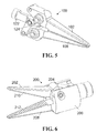
- FIG. 5 is a perspective view of an opposite side of the end effector apparatus shown in FIG. 3 ;
- FIG. 6 is a perspective view of an end effector apparatus according to an alternative disclosed embodiment
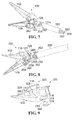
- FIG. 7 is a rear perspective view of the end effector shown in FIG. 2 mounted to a portion of a surgical instrument;
- FIG. 8 is a rear perspective view of the end effector shown in FIG. 7 ;
- FIG. 9 is an exploded view of a revolute joint and a portion of the housing of the end effector shown in FIG. 1 .
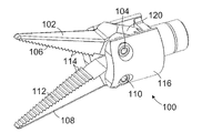
- an end effector apparatus according to a first embodiment of the invention is shown generally at 100 .
- the end-effector 100 will generally be mounted to a surgical instrument (not shown in FIG. 1 ) for performing a surgical procedure.
- a surgical instrument not shown in FIG. 1
- Several different surgical instruments and/or end effectors may be used for surgical tasks performed during a typical surgical procedure.
- the end effector 100 includes a first jaw 102 mounted on a first revolute joint 104 .
- the first jaw 102 has a manipulating portion 106 extending forwardly from the first revolute joint 104 .
- the end-effector 100 also includes a second jaw 108 , which in the embodiment shown is mounted on a second revolute joint 110 .
- the second jaw 108 also has a manipulating portion 112 generally opposing the manipulating portion 106 of the first jaw 102 .
- the manipulating portions 106 and 112 are each oriented toward each other and include a gripping surface comprising teeth 114 for grasping tissue, surgical sutures, suture needles, etc.
- one or both of the manipulating portions 106 and 112 may include a cutting edge for cutting tissue.
- the manipulating portions 106 and 112 may include one or more retractor surfaces oriented away from the manipulating portion of the other of the first and second jaws for manipulating a retractable clamp.
- Various other types of manipulators may be implemented in place of the manipulating portions 106 and 112 shown in FIG. 1 .
- the end-effector 100 includes a housing 116 and the first and second revolute joints 104 and 110 are supported within the housing.
- the first jaw 102 further includes a lever arm 120 (partially obscured by the housing 116 ) projecting rearwardly from the first revolute joint 104 .
- the end-effector 100 is shown with the housing 116 removed in FIG. 2 to reveal the lever arm 120 .
- the end-effector 100 further includes a coupler 122 having a forwardly oriented actuation end 124 and rearwardly oriented interface end 128 .
- the interface end 128 is configured for connecting to control links of a surgical instrument as will be described later herein.
- the actuation end 124 is disposed overlapping the lever arm 120 of the first jaw 102 .
- the second jaw 108 also includes a lever arm 126 projecting rearwardly from the second revolute joint 110 and the first and second jaws 102 and 108 are laterally spaced apart to provide clearance for the actuation end 124 of the coupler 122 between the jaws.
- the end-effector 100 further includes a linkage 130 extending generally rearwardly from the actuation end 124 of the coupler 122 to the lever arm 120 of the first jaw 102 .
- the linkage 130 includes an opening 132 for receiving a pivot pin 134 that extends through the actuation end 124 of the coupler 122 .
- the linkage 130 also includes an opening 136 for receiving a pivot pin 138 that extends through a corresponding opening (not shown) in the lever arm 120 .
- the pivot pins 134 and 138 facilitate movement of the linkage 130 about the pivot pins and the linkage is operable to cause opening and closing movements of the first jaw 102 about the first revolute joint 104 in response to reciprocating movement of the coupler 122 in a direction generally aligned with the arrow 140 .
- the end-effector 100 also includes a linkage associated with movement of the second jaw 108 located on the opposite side of the end effector (not visible in FIG. 2 ). An opposite side of the end-effector 100 is shown in FIG. 3 .
- the end effector 100 also includes a linkage 150 extending generally rearwardly from the actuation end 124 of the coupler 122 to the lever arm 126 of the second jaw 108 .
- the linkage 150 includes an opening 152 for receiving the pivot pin 134 extending through the actuation end 124 of the coupler 122 .
- the pivot pin 134 is common to both linkages 130 and 150 .
- the linkage 150 further includes an opening 156 for receiving a pivot pin 158 that extends through a corresponding opening (not shown) in the lever arm 126 .
- the pivot pins 134 and 158 facilitate movement of the linkage 150 about the pivot pins and the linkage is operable to cause opening and closing movements of the second jaw 108 about the second revolute joint 110 in response to the reciprocating movement of the coupler 122 in the direction 140 .
- the first and second jaws 102 and 108 are shown in an open state, caused by the actuation end 124 of the coupler 122 being disposed forwardly with respect to the jaws. Under these conditions, the first jaw 102 has been rotated to open about the first revolute joint 104 and the second jaw 108 has been rotated to open about the second revolute joint 110 . Referring to FIG. 4 and FIG. 5 , the first and second jaws 102 and 108 are shown in a closed state caused by the actuation end 124 of the coupler 122 having been moved rearwardly with respect to the jaws.
- the coupler 122 is operable to cause the opening movement of the first jaw 102 about the first revolute joint 104 in response to receiving a forwardly directed force at the interface end 128 and to cause a closing movement of the first jaw about the first revolute joint in response to receiving a rearwardly directed force at the interface end of the coupler.
- the configuration of the linkages 130 and 150 shown advantageously provides a greater force closing the jaws 102 and 108 than when opening the jaws.
- an angle ⁇ 2 between the coupler movement direction 140 and the linkage 130 is greater than the angle ⁇ 1 in the open state (shown in FIG. 2 ).
- a tension component of the actuation force in the linkage 130 when opening is significantly reduced over a compression component of the actuation force in the linkage when closing, due to the angle ⁇ 2 being larger than the angle ⁇ 1 .
- the overlapping of the actuation end 124 of the coupler 122 with the first jaw 102 and the linkage 130 extending rearwardly between the actuation end and the lever arm 120 has the advantage of shortening the overall length of the end effector 100 .
- This may be useful in some surgical systems where the end-effector is connected to a surgical instrument that has a dexterous shaft.
- the surgical instrument may be configured as an articulated tool positioner as described in detail in commonly owned patent applications PCT/CA2013/001076 entitled “ARTICULATED TOOL POSITIONER AND SYSTEM EMPLOYING SAME” and PCT/CA2015/000098 entitled “ACTUATOR AND DRIVE FOR MANIPULATING A TOOL” filed on Feb. 18, 2015.
- the articulated tool positioner disclosed in these applications permits dexterous movement of an end effector such as the end effector 100 .
- dexterous manipulation of the end effector itself is not possible, since the jaws and housing are rigid and thus a shortened end effector provides for better access and maneuverability during surgical operations.
- the end effector 200 includes a first jaw 202 mounted for movement on a revolute joint 204 supported with a housing 206 as generally described in connection with the first jaw 102 .
- the end effector 200 also includes a second jaw 208 .
- the second jaw 208 is immovably mounted within the housing 116 and the end effector thus provides for a single ended movement of the first jaw 202 with respect to the second jaw 208 .
- the second jaw is formed integrally with the housing 206 , although in other embodiments the second jaw may be fabricated separately from the housing and otherwise immovably supported.
- the jaws 202 and 208 each include gripper surfaces 210 and 212 , but in other embodiments at least one of the jaws may be configured for cutting, retracting, or other functions.
- the end effector 100 is shown in rear perspective view along with a portion of an outer sheath 250 associated with a surgical instrument (not shown) to which the end effector is connected for operating the end effector 100 .
- the interface end 128 of the coupler 122 has openings 252 , 254 , and 256 for receiving one or more controls associated with the surgical instrument.
- the controls extend though the outer sheath 250 and include a control link 258 for causing the reciprocating movement of the coupler 122 and a pair of electrical conductors 260 and 262 for providing electrical current to the jaws 102 and 108 as described later herein.
- control link 258 may be a rod or a flexible wire such as nitinol that is capable of transmitting both tension and compression forces.
- the control link 258 is received in the opening 254 and may be secured to the coupler by a welding process such as laser welding or may be soldered, crimped, or otherwise connected.
- the end-effector 100 is shown together with a portion of the housing 116 , the remainder of which has been cut away to show the underlying portions of the end effector.
- the outer sheath 250 of the surgical instrument is received in the housing 116 .
- the interface end 128 of the coupler 122 is longitudinally spaced apart from an end 264 of the outer sheath 250 to permit rearward movement of the coupler for closing the jaws.
- the coupler 122 is accommodated in a cylindrical channel 266 that is sized to provide for free reciprocating movement of the coupler for operating the jaws 102 and 108 .
- the electrical conductor 262 is insulated and extends through the opening 256 in the interface end 128 of the coupler 122 .
- the opening 256 is sized to permit free reciprocating movement of the coupler 122 without being impeded by the electrical conductor 262 .
- the second jaw 108 further includes an opening 268 for receiving an end 270 of the electrical conductor 262 from which the insulation has been removed.
- the end 270 of the electrical conductor 262 makes an electrical connection to the second jaw 108 via the opening 268 and may be crimped or soldered, for example.
- the electrical conductor 260 is also insulated and extends through the opening 254 which is also sized to permit free reciprocating movement of the coupler 122 without being impeded by the electrical conductor 260 .
- the first jaw 102 also includes an opening for receiving an end of the electrical conductor 260 from which the insulation has been removed (not visible in FIG. 8 ). The electrical conductor 260 thus also makes electrical connection to the first jaw 102 as shown for the second jaw 108 .
- FIG. 9 an exploded view of the first revolute joint 104 and a portion of the housing 116 is shown generally at 300 .
- the housing 116 and first jaw 102 are both fabricated from an electrically conductive material such as stainless steel.
- the first revolute joint 104 includes a first electrically insulated bushing 302 and a second electrically insulated bushing 304 .
- the housing 116 includes an opening 306 for receiving the first bushing 302 .
- a portion of the housing 116 not shown in FIG. 9 includes an opening for receiving the second bushing 304 .
- the first jaw 102 includes an opening 316 extending through the jaw, and the first revolute joint 104 further includes a pivot pin 318 .
- Each of the bushings 302 and 304 includes a respective opening 308 and 310 for receiving the pivot pin 318 .
- the bushings 302 and 304 also include respective flanges 312 and 314 , disposed facing respective sides of the first jaw 102 . When assembled, the bushings 302 and 304 insulate between the housing 116 and the first jaw 102 .
- the flanges 312 and 314 act as insulating washers that space the first jaw 102 away from the housing 116 on both sides so that portions of the jaw do not contact the housing during operation.
- the pivot pin 318 may also be conductive, but is electrically insulted from the housing 116 by the bushings 302 and 304 .
- the second revolute joint 110 of the second jaw 108 is similarly configured such that each of the jaws is electrically isolated from the housing 116 .
- the first jaw 102 and second jaw 108 are also electrically isolated from each other when open.
- An electrical current received from the surgical instrument through the electrical conductor 260 flows through the first jaw 102 , through any tissue being grasped between the jaws, and through the second jaw 108 and electrical conductor 262 to complete the electrical circuit.
- the current may be selectively controlled by a surgeon operating the surgical instrument for electro-cauterization of tissue during a surgical procedure.
- the configuration of the coupler 122 and the linkages 130 and 150 provides for both increased leverage when closing the jaws 102 and 108 and shortens the overall length of the end effector.
Landscapes
- Health & Medical Sciences (AREA)
- Surgery (AREA)
- Life Sciences & Earth Sciences (AREA)
- Engineering & Computer Science (AREA)
- Biomedical Technology (AREA)
- Public Health (AREA)
- Nuclear Medicine, Radiotherapy & Molecular Imaging (AREA)
- Veterinary Medicine (AREA)
- General Health & Medical Sciences (AREA)
- Heart & Thoracic Surgery (AREA)
- Medical Informatics (AREA)
- Molecular Biology (AREA)
- Animal Behavior & Ethology (AREA)
- Physics & Mathematics (AREA)
- Otolaryngology (AREA)
- Plasma & Fusion (AREA)
- Ophthalmology & Optometry (AREA)
- Robotics (AREA)
- Surgical Instruments (AREA)
Abstract
Description
- This invention relates to apparatus used for surgical procedures and more particularly to an end effector for a robotic and/or laparoscopic surgical instrument.
- Remotely actuated surgical instruments may be used in laparoscopic and/or robotic surgery applications where there is an area of limited access for an operator. The surgical instrument generally includes an end effector disposed at a distal end of a shaft and an actuator portion for manipulating the end effector at a proximate end of a shaft. The end effector and a portion of the surgical instrument inserted through an incision into a body cavity of a patient while the actuator portion generally remains outside the body cavity.
- In accordance with one disclosed aspect there is provided an end effector apparatus for a surgical instrument. The apparatus includes a first jaw mounted on a first revolute joint, the first jaw having a manipulating portion extending forwardly from the first revolute joint and a lever arm projecting rearwardly from the first revolute joint. The apparatus also includes a second jaw having a manipulating portion generally opposing the manipulating portion of the first jaw, and a coupler having an actuation end disposed overlapping the lever arm of the first jaw, the first and second jaws being laterally spaced apart to provide clearance for the actuation end of the coupler. The apparatus further includes a linkage extending rearwardly between the actuation end of the coupler and the lever arm of the first jaw, the linkage being operable to cause opening and closing movements of the first jaw about the first revolute joint in response to reciprocating movement of the coupler.
- The coupler may be operably configured to cause an opening movement of the first jaw about the first revolute joint in response to forward movement of the actuation end of the coupler and to cause a closing movement of the first jaw about the first revolute joint in response to rearward movement of the actuation end of the coupler.
- The rearward movement of the actuation end of the coupler increases an angle between the linkage and the coupler causing a corresponding increase in a component of force transmitted through the linkage for closing the first jaw providing increased leverage for maintaining the first jaw in a closed position.
- The second jaw may be immovably mounted.
- The second jaw may be mounted for movement on a second revolute joint, the second jaw having a lever arm projecting rearwardly from the second revolute joint and may further include a linkage extending rearwardly between the actuation end of the coupler and the lever arm of the second jaw, the linkage being operable to cause opening and closing movements of the second jaw about the second revolute joint in response to reciprocating movement of the actuation end of the coupler.
- The actuating end of the coupler may include an opening for receiving a pivot pin for pivotally mounting to each of the linkages.
- Each of the levers associated with the first and second jaws may include an opening for receiving a pivot pin for pivotally connecting the respective linkages to the respective levers.
- The coupler may have an interface for receiving a control link, the control link being actuated by the surgical instrument for causing movement of the coupler.
- The apparatus may include a housing operable to support the first and second revolute joints.
- Each of the revolute joints may include a pivot pin supported within the housing and extending through an opening in the respective first and second jaws.
- The housing may include an interface for removably mounting the end effector to a distal end of the surgical instrument.
- Each pivot pin may be supported between a pair of electrically insulating bushings received in respective openings disposed on either side of the first jaw, the electrically insulated bushings being operable to electrically isolate the respective jaws from the housing.
- Each of the first and second jaws may further include an electrical connection for connecting to respective electrical conductors associated with the surgical instrument, the electrical conductors being operable to supply an electrical current through the respective jaws.
- The manipulating portion of at least one of the first and second jaws may include a cutting edge oriented toward the manipulating portion of the other of the first and second jaws for cutting tissue, a gripping surface oriented toward the manipulating portion of the other of the first and second jaws for grasping, and a retractor surface oriented away from the manipulating portion of the other of the first and second jaws for manipulating a retractable clamp.
- The apparatus may include a housing surrounding at least the first revolute joint and the first revolute joint may include a pivot pin supported within the housing and extending through an opening in the first jaw.
- The housing may include an interface for removably mounting the end effector to a distal end of the surgical instrument.
- The pivot pin may be supported between a pair of electrically insulating bushings received in respective openings disposed on either side of the first jaw, the electrically insulated bushings being operable to electrically isolate the first jaw from the housing.
- The first jaw may further include an electrical connection for connecting to an electrical conductor associated with the surgical instrument, the electrical conductor for supplying an electrical current through the first jaw.
- In accordance with another disclosed aspect there is provided a method for actuating an end effector for a surgical instrument, the end effector including a first jaw mounted on a first revolute joint, the first jaw having a manipulating portion extending forwardly from the first revolute joint and a lever arm projecting rearwardly from the first revolute joint, a second jaw having a manipulating portion generally opposing the manipulating portion of the first jaw. The method involves causing reciprocating movement of a coupler having an actuation end disposed overlapping the lever arm of the first jaw, the first and second jaws being laterally spaced apart to provide clearance for the actuation end of the coupler, and transmitting reciprocating movements of the coupler through a linkage extending rearwardly between the actuation end of the coupler and the lever arm of the first jaw, the movement of the linkage being operable to cause opening and closing movements of the first jaw about the first revolute joint.
- Other aspects and features of the present invention will become apparent to those ordinarily skilled in the art upon review of the following description of specific embodiments of the invention in conjunction with the accompanying figures.
- In drawings which illustrate embodiments of the invention,
-
FIG. 1 is a perspective view of an end effector apparatus according to a first disclosed embodiment; -
FIG. 2 is a perspective view of the end effector apparatus ofFIG. 1 with a housing portion removed; -
FIG. 3 is a perspective view of an opposite side of the end effector apparatus shown inFIG. 2 ; -
FIG. 4 is a perspective view of the end effector shown inFIG. 2 in a closed state; -
FIG. 5 is a perspective view of an opposite side of the end effector apparatus shown inFIG. 3 ; -
FIG. 6 is a perspective view of an end effector apparatus according to an alternative disclosed embodiment; -
FIG. 7 is a rear perspective view of the end effector shown inFIG. 2 mounted to a portion of a surgical instrument; -
FIG. 8 is a rear perspective view of the end effector shown inFIG. 7 ; and -
FIG. 9 is an exploded view of a revolute joint and a portion of the housing of the end effector shown inFIG. 1 . - Referring to
FIG. 1 , an end effector apparatus according to a first embodiment of the invention is shown generally at 100. The end-effector 100 will generally be mounted to a surgical instrument (not shown inFIG. 1 ) for performing a surgical procedure. Several different surgical instruments and/or end effectors may be used for surgical tasks performed during a typical surgical procedure. - The
end effector 100 includes afirst jaw 102 mounted on a firstrevolute joint 104. Thefirst jaw 102 has a manipulatingportion 106 extending forwardly from the firstrevolute joint 104. The end-effector 100 also includes asecond jaw 108, which in the embodiment shown is mounted on a secondrevolute joint 110. Thesecond jaw 108 also has a manipulatingportion 112 generally opposing the manipulatingportion 106 of thefirst jaw 102. In the embodiment shown the manipulatingportions surface comprising teeth 114 for grasping tissue, surgical sutures, suture needles, etc. In other embodiments one or both of the manipulatingportions portions portions FIG. 1 . - In the embodiment shown in
FIG. 1 , the end-effector 100 includes ahousing 116 and the first andsecond revolute joints first jaw 102 further includes a lever arm 120 (partially obscured by the housing 116) projecting rearwardly from the firstrevolute joint 104. Referring toFIG. 2 , the end-effector 100 is shown with thehousing 116 removed inFIG. 2 to reveal thelever arm 120. The end-effector 100 further includes acoupler 122 having a forwardly orientedactuation end 124 and rearwardly orientedinterface end 128. Theinterface end 128 is configured for connecting to control links of a surgical instrument as will be described later herein. Theactuation end 124 is disposed overlapping thelever arm 120 of thefirst jaw 102. Thesecond jaw 108 also includes alever arm 126 projecting rearwardly from the secondrevolute joint 110 and the first andsecond jaws actuation end 124 of thecoupler 122 between the jaws. - The end-
effector 100 further includes alinkage 130 extending generally rearwardly from theactuation end 124 of thecoupler 122 to thelever arm 120 of thefirst jaw 102. In this embodiment thelinkage 130 includes an opening 132 for receiving apivot pin 134 that extends through theactuation end 124 of thecoupler 122. Thelinkage 130 also includes anopening 136 for receiving apivot pin 138 that extends through a corresponding opening (not shown) in thelever arm 120. The pivot pins 134 and 138 facilitate movement of thelinkage 130 about the pivot pins and the linkage is operable to cause opening and closing movements of thefirst jaw 102 about the first revolute joint 104 in response to reciprocating movement of thecoupler 122 in a direction generally aligned with thearrow 140. - The end-
effector 100 also includes a linkage associated with movement of thesecond jaw 108 located on the opposite side of the end effector (not visible inFIG. 2 ). An opposite side of the end-effector 100 is shown inFIG. 3 . Referring toFIG. 3 , theend effector 100 also includes alinkage 150 extending generally rearwardly from theactuation end 124 of thecoupler 122 to thelever arm 126 of thesecond jaw 108. Thelinkage 150 includes anopening 152 for receiving thepivot pin 134 extending through theactuation end 124 of thecoupler 122. In this embodiment thepivot pin 134 is common to bothlinkages linkage 150 further includes anopening 156 for receiving apivot pin 158 that extends through a corresponding opening (not shown) in thelever arm 126. The pivot pins 134 and 158 facilitate movement of thelinkage 150 about the pivot pins and the linkage is operable to cause opening and closing movements of thesecond jaw 108 about the second revolute joint 110 in response to the reciprocating movement of thecoupler 122 in thedirection 140. - Referring back to
FIG. 2 , the first andsecond jaws actuation end 124 of thecoupler 122 being disposed forwardly with respect to the jaws. Under these conditions, thefirst jaw 102 has been rotated to open about the first revolute joint 104 and thesecond jaw 108 has been rotated to open about the second revolute joint 110. Referring toFIG. 4 andFIG. 5 , the first andsecond jaws actuation end 124 of thecoupler 122 having been moved rearwardly with respect to the jaws. Under these conditions, thefirst jaw 102 has been rotated to close about the first revolute joint 104 and thesecond jaw 108 has been rotated to close about the second revolute joint 110. Thecoupler 122 is operable to cause the opening movement of thefirst jaw 102 about the first revolute joint 104 in response to receiving a forwardly directed force at theinterface end 128 and to cause a closing movement of the first jaw about the first revolute joint in response to receiving a rearwardly directed force at the interface end of the coupler. - The configuration of the
linkages jaws jaws FIG. 4 , an angle α2 between thecoupler movement direction 140 and thelinkage 130 is greater than the angle α1 in the open state (shown inFIG. 2 ). For a similar actuation force exerted on the forwardly orientedactuation end 124 and rearwardly orientedinterface end 128 of thecoupler 122, a tension component of the actuation force in thelinkage 130 when opening is significantly reduced over a compression component of the actuation force in the linkage when closing, due to the angle α2 being larger than the angle α1. Thus, rearward movement of theactuation end 124 of thecoupler 122 increases the angle α between thelinkage 130 and the coupler causing a corresponding increase in the component of force transmitted through the linkage for closing the first jaw. The same effect also occurs in connection with thelinkage 150 associated with thesecond jaw 108, thus providing increased leverage for grasping and maintaining the jaws in a closed position. - The overlapping of the
actuation end 124 of thecoupler 122 with thefirst jaw 102 and thelinkage 130 extending rearwardly between the actuation end and thelever arm 120 has the advantage of shortening the overall length of theend effector 100. This may be useful in some surgical systems where the end-effector is connected to a surgical instrument that has a dexterous shaft. For example, the surgical instrument may be configured as an articulated tool positioner as described in detail in commonly owned patent applications PCT/CA2013/001076 entitled “ARTICULATED TOOL POSITIONER AND SYSTEM EMPLOYING SAME” and PCT/CA2015/000098 entitled “ACTUATOR AND DRIVE FOR MANIPULATING A TOOL” filed on Feb. 18, 2015. The articulated tool positioner disclosed in these applications permits dexterous movement of an end effector such as theend effector 100. However dexterous manipulation of the end effector itself is not possible, since the jaws and housing are rigid and thus a shortened end effector provides for better access and maneuverability during surgical operations. - Referring to
FIG. 6 , an alternative embodiment of the end effector shown generally at 200. In this embodiment theend effector 200 includes afirst jaw 202 mounted for movement on a revolute joint 204 supported with ahousing 206 as generally described in connection with thefirst jaw 102. Theend effector 200 also includes asecond jaw 208. However in thus embodiment thesecond jaw 208 is immovably mounted within thehousing 116 and the end effector thus provides for a single ended movement of thefirst jaw 202 with respect to thesecond jaw 208. In this embodiment the second jaw is formed integrally with thehousing 206, although in other embodiments the second jaw may be fabricated separately from the housing and otherwise immovably supported. As in the case of the embodiments shown inFIG. 1-5 thejaws - Referring to
FIG. 7 , theend effector 100 is shown in rear perspective view along with a portion of anouter sheath 250 associated with a surgical instrument (not shown) to which the end effector is connected for operating theend effector 100. Theinterface end 128 of thecoupler 122 hasopenings outer sheath 250 and include acontrol link 258 for causing the reciprocating movement of thecoupler 122 and a pair ofelectrical conductors jaws control link 258 may be a rod or a flexible wire such as nitinol that is capable of transmitting both tension and compression forces. The control link 258 is received in theopening 254 and may be secured to the coupler by a welding process such as laser welding or may be soldered, crimped, or otherwise connected. - Referring to
FIG. 8 , the end-effector 100 is shown together with a portion of thehousing 116, the remainder of which has been cut away to show the underlying portions of the end effector. Theouter sheath 250 of the surgical instrument is received in thehousing 116. In the state shown where thecoupler 122 is disposed in a forward position for opening thejaws interface end 128 of thecoupler 122 is longitudinally spaced apart from anend 264 of theouter sheath 250 to permit rearward movement of the coupler for closing the jaws. Thecoupler 122 is accommodated in acylindrical channel 266 that is sized to provide for free reciprocating movement of the coupler for operating thejaws - Still referring to
FIG. 8 , theelectrical conductor 262 is insulated and extends through theopening 256 in theinterface end 128 of thecoupler 122. Theopening 256 is sized to permit free reciprocating movement of thecoupler 122 without being impeded by theelectrical conductor 262. Thesecond jaw 108 further includes anopening 268 for receiving an end 270 of theelectrical conductor 262 from which the insulation has been removed. The end 270 of theelectrical conductor 262 makes an electrical connection to thesecond jaw 108 via theopening 268 and may be crimped or soldered, for example. Similarly theelectrical conductor 260 is also insulated and extends through theopening 254 which is also sized to permit free reciprocating movement of thecoupler 122 without being impeded by theelectrical conductor 260. Thefirst jaw 102 also includes an opening for receiving an end of theelectrical conductor 260 from which the insulation has been removed (not visible inFIG. 8 ). Theelectrical conductor 260 thus also makes electrical connection to thefirst jaw 102 as shown for thesecond jaw 108. - Referring to
FIG. 9 , an exploded view of the first revolute joint 104 and a portion of thehousing 116 is shown generally at 300. In the embodiment shown thehousing 116 andfirst jaw 102 are both fabricated from an electrically conductive material such as stainless steel. The first revolute joint 104 includes a first electrically insulatedbushing 302 and a second electrically insulatedbushing 304. Thehousing 116 includes anopening 306 for receiving thefirst bushing 302. Similarly, a portion of thehousing 116 not shown inFIG. 9 includes an opening for receiving thesecond bushing 304. Thefirst jaw 102 includes anopening 316 extending through the jaw, and the first revolute joint 104 further includes apivot pin 318. Each of thebushings respective opening pivot pin 318. Thebushings respective flanges first jaw 102. When assembled, thebushings housing 116 and thefirst jaw 102. Theflanges first jaw 102 away from thehousing 116 on both sides so that portions of the jaw do not contact the housing during operation. Thepivot pin 318 may also be conductive, but is electrically insulted from thehousing 116 by thebushings second jaw 108 is similarly configured such that each of the jaws is electrically isolated from thehousing 116. Thefirst jaw 102 andsecond jaw 108 are also electrically isolated from each other when open. An electrical current received from the surgical instrument through theelectrical conductor 260 flows through thefirst jaw 102, through any tissue being grasped between the jaws, and through thesecond jaw 108 andelectrical conductor 262 to complete the electrical circuit. The current may be selectively controlled by a surgeon operating the surgical instrument for electro-cauterization of tissue during a surgical procedure. - In the disclosed embodiments the configuration of the
coupler 122 and thelinkages jaws - While specific embodiments of the invention have been described and illustrated, such embodiments should be considered illustrative of the invention only and not as limiting the invention as construed in accordance with the accompanying claims.
Claims (19)
Priority Applications (1)
| Application Number | Priority Date | Filing Date | Title |
|---|---|---|---|
| US15/566,525 US10945748B2 (en) | 2015-04-14 | 2016-02-29 | End effector apparatus for a surgical instrument |
Applications Claiming Priority (3)
| Application Number | Priority Date | Filing Date | Title |
|---|---|---|---|
| US201562147302P | 2015-04-14 | 2015-04-14 | |
| PCT/CA2016/000059 WO2016165004A1 (en) | 2015-04-14 | 2016-02-29 | End effector apparatus for a surgical instrument |
| US15/566,525 US10945748B2 (en) | 2015-04-14 | 2016-02-29 | End effector apparatus for a surgical instrument |
Publications (2)
| Publication Number | Publication Date |
|---|---|
| US20180098780A1 true US20180098780A1 (en) | 2018-04-12 |
| US10945748B2 US10945748B2 (en) | 2021-03-16 |
Family
ID=57125633
Family Applications (1)
| Application Number | Title | Priority Date | Filing Date |
|---|---|---|---|
| US15/566,525 Active 2036-04-21 US10945748B2 (en) | 2015-04-14 | 2016-02-29 | End effector apparatus for a surgical instrument |
Country Status (3)
| Country | Link |
|---|---|
| US (1) | US10945748B2 (en) |
| CA (1) | CA2982615C (en) |
| WO (1) | WO2016165004A1 (en) |
Cited By (8)
| Publication number | Priority date | Publication date | Assignee | Title |
|---|---|---|---|---|
| CN109009414A (en) * | 2018-08-23 | 2018-12-18 | 微创(上海)医疗机器人有限公司 | Surgical instrument and its end effector |
| CN110772333A (en) * | 2019-04-25 | 2020-02-11 | 深圳市精锋医疗科技有限公司 | Tip instrument and surgical instrument |
| US11273932B2 (en) | 2017-09-10 | 2022-03-15 | Space Arena, Inc. | Enclosures for facilitating activities in space, and associated systems and methods |
| US11358739B2 (en) | 2017-09-10 | 2022-06-14 | Orbit Fab, Inc. | Systems and methods for delivering, storing, and processing materials in space |
| US11364067B2 (en) * | 2017-10-06 | 2022-06-21 | Cilag Gmbh International | Electrical isolation of electrosurgical instruments |
| US20220226050A1 (en) * | 2021-01-21 | 2022-07-21 | Ethicon Llc | Surgical tool end effectors with wire routing distal wedge |
| US20220226052A1 (en) * | 2021-01-21 | 2022-07-21 | Ethicon Llc | Articulable wrists for surgical tool end effectors |
| US12017524B2 (en) | 2017-12-06 | 2024-06-25 | Orbit Fab, Inc. | Systems and methods for creating and automating an enclosed volume with a flexible fuel tank and propellant metering for machine operations |
Families Citing this family (5)
| Publication number | Priority date | Publication date | Assignee | Title |
|---|---|---|---|---|
| US9895200B2 (en) | 2014-04-22 | 2018-02-20 | Bio-Medical Engineering (HK) Limited | Robotic devices and systems for performing single incision procedures and natural orifice translumenal endoscopic surgical procedures, and methods of configuring robotic devices and systems |
| US10500008B2 (en) | 2014-04-22 | 2019-12-10 | Bio-Medical Engineering (HK) Limited | Surgical arm system with internally driven gear assemblies |
| US9827058B1 (en) | 2016-11-01 | 2017-11-28 | Bio-Medical Engineering (HK) Limited | Surgical robotic devices and systems for use in performing minimally invasive and natural orifice transluminal endoscopic surgical actions |
| US11950871B2 (en) | 2018-01-16 | 2024-04-09 | Multi Scopic Instruments, Llc | End effector |
| US10709517B2 (en) | 2018-01-16 | 2020-07-14 | Multi Scopic Instruments, Llc | End effector |
Citations (7)
| Publication number | Priority date | Publication date | Assignee | Title |
|---|---|---|---|---|
| US4038987A (en) * | 1974-02-08 | 1977-08-02 | Olympus Optical Co., Ltd. | Forceps device for endoscope |
| US5392789A (en) * | 1991-04-04 | 1995-02-28 | Symbiosis Corporation | Endoscopic scissors having scissor elements loosely engaged with a clevis |
| US6840938B1 (en) * | 2000-12-29 | 2005-01-11 | Intuitive Surgical, Inc. | Bipolar cauterizing instrument |
| US20100198253A1 (en) * | 2009-02-03 | 2010-08-05 | Terumo Kabushiki Kaisha | Medical manipulator |
| US20110137337A1 (en) * | 2008-05-30 | 2011-06-09 | Vieugels Holding B.V. | Instrument for Minimally Invasive Surgery |
| US20120259319A1 (en) * | 2011-04-11 | 2012-10-11 | Jochen Stefan | Tool for a micro-invasive surgical instrument |
| US8568443B1 (en) * | 2008-05-21 | 2013-10-29 | Encision, Inc. | Surgical grapser tool and actuation mechanism |
Family Cites Families (9)
| Publication number | Priority date | Publication date | Assignee | Title |
|---|---|---|---|---|
| FR2694180B1 (en) * | 1992-07-31 | 1994-10-21 | Alain Martin | Angular laparoscopic forceps. |
| US5312434A (en) * | 1992-12-21 | 1994-05-17 | Lawrence Crainich | Medical instrument |
| US7775989B2 (en) * | 2003-09-03 | 2010-08-17 | Granit Medical Innovations, Llc | Needle biopsy forceps with integral sample ejector |
| US8758342B2 (en) | 2007-11-28 | 2014-06-24 | Covidien Ag | Cordless power-assisted medical cauterization and cutting device |
| US20100298864A1 (en) | 2009-01-15 | 2010-11-25 | Michael Castro | Articulating rigid grasper |
| WO2010124129A1 (en) | 2009-04-22 | 2010-10-28 | Pare Surgical, Inc. | Endoscopic tissue grasping apparatus and method |
| US8672939B2 (en) | 2010-06-01 | 2014-03-18 | Covidien Lp | Surgical device for performing an electrosurgical procedure |
| DK2627263T3 (en) * | 2010-10-11 | 2017-03-06 | Cook Medical Technologies Llc | MEDICAL DEVICES WITH THIRD Jaws |
| US8968340B2 (en) * | 2011-02-23 | 2015-03-03 | Covidien Lp | Single actuating jaw flexible endolumenal stitching device |
-
2016
- 2016-02-29 US US15/566,525 patent/US10945748B2/en active Active
- 2016-02-29 CA CA2982615A patent/CA2982615C/en active Active
- 2016-02-29 WO PCT/CA2016/000059 patent/WO2016165004A1/en not_active Ceased
Patent Citations (7)
| Publication number | Priority date | Publication date | Assignee | Title |
|---|---|---|---|---|
| US4038987A (en) * | 1974-02-08 | 1977-08-02 | Olympus Optical Co., Ltd. | Forceps device for endoscope |
| US5392789A (en) * | 1991-04-04 | 1995-02-28 | Symbiosis Corporation | Endoscopic scissors having scissor elements loosely engaged with a clevis |
| US6840938B1 (en) * | 2000-12-29 | 2005-01-11 | Intuitive Surgical, Inc. | Bipolar cauterizing instrument |
| US8568443B1 (en) * | 2008-05-21 | 2013-10-29 | Encision, Inc. | Surgical grapser tool and actuation mechanism |
| US20110137337A1 (en) * | 2008-05-30 | 2011-06-09 | Vieugels Holding B.V. | Instrument for Minimally Invasive Surgery |
| US20100198253A1 (en) * | 2009-02-03 | 2010-08-05 | Terumo Kabushiki Kaisha | Medical manipulator |
| US20120259319A1 (en) * | 2011-04-11 | 2012-10-11 | Jochen Stefan | Tool for a micro-invasive surgical instrument |
Cited By (12)
| Publication number | Priority date | Publication date | Assignee | Title |
|---|---|---|---|---|
| US11273932B2 (en) | 2017-09-10 | 2022-03-15 | Space Arena, Inc. | Enclosures for facilitating activities in space, and associated systems and methods |
| US11358739B2 (en) | 2017-09-10 | 2022-06-14 | Orbit Fab, Inc. | Systems and methods for delivering, storing, and processing materials in space |
| US12037142B2 (en) | 2017-09-10 | 2024-07-16 | Space Arena, Inc. | Enclosures for facilitating activities in space, and associated systems and methods |
| US12116148B2 (en) | 2017-09-10 | 2024-10-15 | Orbit Fab, Inc. | Systems and methods for delivering, storing, and processing materials in space |
| US12438106B2 (en) | 2017-09-10 | 2025-10-07 | Space Arena, Inc. | Enclosures for facilitating activities in space, and associated systems and methods |
| US11364067B2 (en) * | 2017-10-06 | 2022-06-21 | Cilag Gmbh International | Electrical isolation of electrosurgical instruments |
| US12017524B2 (en) | 2017-12-06 | 2024-06-25 | Orbit Fab, Inc. | Systems and methods for creating and automating an enclosed volume with a flexible fuel tank and propellant metering for machine operations |
| CN109009414A (en) * | 2018-08-23 | 2018-12-18 | 微创(上海)医疗机器人有限公司 | Surgical instrument and its end effector |
| CN110772333A (en) * | 2019-04-25 | 2020-02-11 | 深圳市精锋医疗科技有限公司 | Tip instrument and surgical instrument |
| US20220226050A1 (en) * | 2021-01-21 | 2022-07-21 | Ethicon Llc | Surgical tool end effectors with wire routing distal wedge |
| US20220226052A1 (en) * | 2021-01-21 | 2022-07-21 | Ethicon Llc | Articulable wrists for surgical tool end effectors |
| US11806099B2 (en) * | 2021-01-21 | 2023-11-07 | Cilag Gmbh International | Articulable wrists for surgical tool end effectors |
Also Published As
| Publication number | Publication date |
|---|---|
| CA2982615C (en) | 2018-03-20 |
| WO2016165004A1 (en) | 2016-10-20 |
| US10945748B2 (en) | 2021-03-16 |
| CA2982615A1 (en) | 2016-10-20 |
Similar Documents
| Publication | Publication Date | Title |
|---|---|---|
| CA2982615C (en) | End effector apparatus for a surgical instrument | |
| US11712288B2 (en) | Bipolar end effector apparatus for a surgical instrument | |
| KR102729909B1 (en) | Supplying electrical energy to electrosurgical instruments | |
| CN113226209B (en) | Distal closure mechanism for surgical instrument | |
| US7276066B2 (en) | Medical instrument for endoscope | |
| KR102006471B1 (en) | Bipolar cautery instrument | |
| EP2753260B1 (en) | Apparatus for performing electrosurgical procedures having a spring mechanism associated with the jaw members | |
| EP2470106B1 (en) | Direct pull surgical gripper | |
| EP4295796A1 (en) | End tool of surgical instrument and surgical instrument comprising same for electrocautery | |
| US20240299081A1 (en) | Knife assemblies for use with surgical instruments and systems | |
| US11241275B2 (en) | Energy-based surgical instrument having multiple operational configurations | |
| US12569271B2 (en) | Surgical instruments, systems, and methods incorporating an ultrasonic transducer | |
| CN116867447A (en) | End effector drive mechanisms such as those used in surgical instruments in robotic surgical systems | |
| US12383329B2 (en) | Gripping device and treatment tool | |
| US12161386B2 (en) | Surgical instruments having an articulating section such as for use in robotic surgical systems | |
| US20200179037A1 (en) | Knife assemblies for use with surgical instruments and systems | |
| JP7146015B2 (en) | drive shaft for surgical instruments | |
| EP4721685A1 (en) | Instrument for electrocautery surgery | |
| US20250228606A1 (en) | Operation part for surgical instrument and electrocautery surgical instrument equipped with operation part | |
| US12484926B2 (en) | Surgical instruments, systems, and methods incorporating an offset end effector | |
| CN114176781A (en) | End effector assembly for a surgical instrument | |
| CN114176780A (en) | End effector assembly for a surgical instrument |
Legal Events
| Date | Code | Title | Description |
|---|---|---|---|
| FEPP | Fee payment procedure |
Free format text: ENTITY STATUS SET TO UNDISCOUNTED (ORIGINAL EVENT CODE: BIG.); ENTITY STATUS OF PATENT OWNER: LARGE ENTITY |
|
| AS | Assignment |
Owner name: TITAN MEDICAL INC., CANADA Free format text: ASSIGNMENT OF ASSIGNORS INTEREST;ASSIGNOR:XIMEDICA, LLC;REEL/FRAME:043962/0248 Effective date: 20160223 Owner name: XIMEDICA, LLC, RHODE ISLAND Free format text: ASSIGNMENT OF ASSIGNORS INTEREST;ASSIGNOR:ROBERT, RENE;REEL/FRAME:043962/0244 Effective date: 20160217 |
|
| FEPP | Fee payment procedure |
Free format text: ENTITY STATUS SET TO SMALL (ORIGINAL EVENT CODE: SMAL); ENTITY STATUS OF PATENT OWNER: LARGE ENTITY |
|
| STPP | Information on status: patent application and granting procedure in general |
Free format text: DOCKETED NEW CASE - READY FOR EXAMINATION |
|
| STPP | Information on status: patent application and granting procedure in general |
Free format text: NON FINAL ACTION MAILED |
|
| STPP | Information on status: patent application and granting procedure in general |
Free format text: RESPONSE TO NON-FINAL OFFICE ACTION ENTERED AND FORWARDED TO EXAMINER |
|
| STPP | Information on status: patent application and granting procedure in general |
Free format text: FINAL REJECTION MAILED |
|
| STPP | Information on status: patent application and granting procedure in general |
Free format text: RESPONSE AFTER FINAL ACTION FORWARDED TO EXAMINER |
|
| STPP | Information on status: patent application and granting procedure in general |
Free format text: ADVISORY ACTION MAILED |
|
| STPP | Information on status: patent application and granting procedure in general |
Free format text: DOCKETED NEW CASE - READY FOR EXAMINATION |
|
| AS | Assignment |
Owner name: CORPORATION SERVICE COMPANY C/O PROJECT TIME LLC, DELAWARE Free format text: SECURITY INTEREST;ASSIGNOR:TITAN MEDICAL INC.;REEL/FRAME:052643/0922 Effective date: 20200508 |
|
| FEPP | Fee payment procedure |
Free format text: ENTITY STATUS SET TO UNDISCOUNTED (ORIGINAL EVENT CODE: BIG.); ENTITY STATUS OF PATENT OWNER: LARGE ENTITY |
|
| STCF | Information on status: patent grant |
Free format text: PATENTED CASE |
|
| AS | Assignment |
Owner name: TITAN MEDICAL INC., CANADA Free format text: RELEASE BY SECURED PARTY;ASSIGNOR:PROJECT TIME LLC;REEL/FRAME:059174/0081 Effective date: 20220131 |
|
| AS | Assignment |
Owner name: COVIDIEN LP, MASSACHUSETTS Free format text: ASSIGNMENT OF ASSIGNORS INTEREST;ASSIGNOR:TITAN MEDICAL INC.;REEL/FRAME:064347/0923 Effective date: 20230605 |
|
| MAFP | Maintenance fee payment |
Free format text: PAYMENT OF MAINTENANCE FEE, 4TH YEAR, LARGE ENTITY (ORIGINAL EVENT CODE: M1551); ENTITY STATUS OF PATENT OWNER: LARGE ENTITY Year of fee payment: 4 |