US20180098762A1 - Snap lock - Google Patents
Snap lock Download PDFInfo
- Publication number
- US20180098762A1 US20180098762A1 US15/729,054 US201715729054A US2018098762A1 US 20180098762 A1 US20180098762 A1 US 20180098762A1 US 201715729054 A US201715729054 A US 201715729054A US 2018098762 A1 US2018098762 A1 US 2018098762A1
- Authority
- US
- United States
- Prior art keywords
- suture
- piece
- lock
- snap lock
- plug
- Prior art date
- Legal status (The legal status is an assumption and is not a legal conclusion. Google has not performed a legal analysis and makes no representation as to the accuracy of the status listed.)
- Granted
Links
Images


Classifications
-
- A—HUMAN NECESSITIES
- A61—MEDICAL OR VETERINARY SCIENCE; HYGIENE
- A61B—DIAGNOSIS; SURGERY; IDENTIFICATION
- A61B17/00—Surgical instruments, devices or methods
- A61B17/04—Surgical instruments, devices or methods for suturing wounds; Holders or packages for needles or suture materials
- A61B17/0401—Suture anchors, buttons or pledgets, i.e. means for attaching sutures to bone, cartilage or soft tissue; Instruments for applying or removing suture anchors
-
- A—HUMAN NECESSITIES
- A61—MEDICAL OR VETERINARY SCIENCE; HYGIENE
- A61B—DIAGNOSIS; SURGERY; IDENTIFICATION
- A61B17/00—Surgical instruments, devices or methods
- A61B17/04—Surgical instruments, devices or methods for suturing wounds; Holders or packages for needles or suture materials
- A61B17/06—Needles ; Sutures; Needle-suture combinations; Holders or packages for needles or suture materials
- A61B17/06166—Sutures
-
- A—HUMAN NECESSITIES
- A61—MEDICAL OR VETERINARY SCIENCE; HYGIENE
- A61B—DIAGNOSIS; SURGERY; IDENTIFICATION
- A61B17/00—Surgical instruments, devices or methods
- A61B17/04—Surgical instruments, devices or methods for suturing wounds; Holders or packages for needles or suture materials
- A61B17/0401—Suture anchors, buttons or pledgets, i.e. means for attaching sutures to bone, cartilage or soft tissue; Instruments for applying or removing suture anchors
- A61B2017/0403—Dowels
-
- A—HUMAN NECESSITIES
- A61—MEDICAL OR VETERINARY SCIENCE; HYGIENE
- A61B—DIAGNOSIS; SURGERY; IDENTIFICATION
- A61B17/00—Surgical instruments, devices or methods
- A61B17/04—Surgical instruments, devices or methods for suturing wounds; Holders or packages for needles or suture materials
- A61B17/0401—Suture anchors, buttons or pledgets, i.e. means for attaching sutures to bone, cartilage or soft tissue; Instruments for applying or removing suture anchors
- A61B2017/0409—Instruments for applying suture anchors
-
- A—HUMAN NECESSITIES
- A61—MEDICAL OR VETERINARY SCIENCE; HYGIENE
- A61B—DIAGNOSIS; SURGERY; IDENTIFICATION
- A61B17/00—Surgical instruments, devices or methods
- A61B17/04—Surgical instruments, devices or methods for suturing wounds; Holders or packages for needles or suture materials
- A61B17/0401—Suture anchors, buttons or pledgets, i.e. means for attaching sutures to bone, cartilage or soft tissue; Instruments for applying or removing suture anchors
- A61B2017/0414—Suture anchors, buttons or pledgets, i.e. means for attaching sutures to bone, cartilage or soft tissue; Instruments for applying or removing suture anchors having a suture-receiving opening, e.g. lateral opening
-
- A—HUMAN NECESSITIES
- A61—MEDICAL OR VETERINARY SCIENCE; HYGIENE
- A61B—DIAGNOSIS; SURGERY; IDENTIFICATION
- A61B17/00—Surgical instruments, devices or methods
- A61B17/04—Surgical instruments, devices or methods for suturing wounds; Holders or packages for needles or suture materials
- A61B17/0401—Suture anchors, buttons or pledgets, i.e. means for attaching sutures to bone, cartilage or soft tissue; Instruments for applying or removing suture anchors
- A61B2017/044—Suture anchors, buttons or pledgets, i.e. means for attaching sutures to bone, cartilage or soft tissue; Instruments for applying or removing suture anchors with a threaded shaft, e.g. screws
-
- A—HUMAN NECESSITIES
- A61—MEDICAL OR VETERINARY SCIENCE; HYGIENE
- A61B—DIAGNOSIS; SURGERY; IDENTIFICATION
- A61B17/00—Surgical instruments, devices or methods
- A61B17/04—Surgical instruments, devices or methods for suturing wounds; Holders or packages for needles or suture materials
- A61B17/0401—Suture anchors, buttons or pledgets, i.e. means for attaching sutures to bone, cartilage or soft tissue; Instruments for applying or removing suture anchors
- A61B2017/0446—Means for attaching and blocking the suture in the suture anchor
- A61B2017/0448—Additional elements on or within the anchor
- A61B2017/045—Additional elements on or within the anchor snug fit within the anchor
-
- A—HUMAN NECESSITIES
- A61—MEDICAL OR VETERINARY SCIENCE; HYGIENE
- A61B—DIAGNOSIS; SURGERY; IDENTIFICATION
- A61B17/00—Surgical instruments, devices or methods
- A61B17/04—Surgical instruments, devices or methods for suturing wounds; Holders or packages for needles or suture materials
- A61B2017/0496—Surgical instruments, devices or methods for suturing wounds; Holders or packages for needles or suture materials for tensioning sutures
Definitions
- the invention relates generally to the field of surgery and is intended to allow for improved fixation of soft tissue to bone.
- the snap lock and method of implementation according to the present invention overcome the drawbacks of known suture lock devices and methods of implementation by providing multiple points of fixation of the suture and without knotting the suture.
- This invention relates to an apparatus and method for suspending suture from bone and providing a secure fixation of the suture within the device.
- the specific design of the device allows for tensioning of various sized suture material or suture tape that has been passed through the device.
- a second internal member of the apparatus is advanced and snapped into the apparatus which provides for multiple points of fixation against the suture.
- the unique internal compression mechanism allows for three different points of compression against the suture material which allows for superior fixation.
- Embodiments of the presently described snap lock accomplish knotless fixation of soft tissue to bone.
- the present snap lock is intended to be used in the reconstruction of soft tissue disruption such as ligament or tendon tears.
- This lock and its implementation avoid the need for suture tying and are intended for use in various areas of the musculoskeletal system.
- the body part may be rehabilitated more aggressively and thereby reducing postoperative complications such as stiffness of a joint and improve recovery time following surgery.
- Implementation of the present snap lock includes drilling or reaming a desired size hole into bone. Sutures are then passed through the hole and then passed through the lock. The lock is then inserted into the hole and pressed against the bone. The sutures are then pulled through the lock to the desired tension. The tissue intended for fixation has already been attached to the opposite end of the sutures. Once satisfactory positioning of the tissue is achieved, the snap lock is operated or tightened by advancing the internal piece which snaps into place when fully seated into the outer piece. This locks and compresses the sutures against the inner wall of the outer piece. This allows for completion of the ligament fixation.
- the present invention allows for fastening of suture through a predrilled hole by compression of the suture between pieces of the apparatus. Prior to passing the suture through the device, it is attached to tissue (such as ligament, tendon, or bone) that is intended to be “fixed”.
- tissue such as ligament, tendon, or bone
- FIG. 1 is a perspective top view of a preferred embodiment snap lock outer piece
- FIG. 2 is a perspective top side view of the snap lock outer piece
- FIG. 3 is a perspective side view of the snap lock outer piece with a view of the anti-rotational slot
- FIG. 4 is a perspective side view of the snap lock outer piece of the side without the anti-rotational slot
- FIG. 5 is a perspective cross section side view of the snap lock outer piece of the inside of the outer piece demonstrating the tapered inner portion
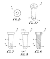
- FIG. 6 is a perspective top view of the snap lock inner piece
- FIG. 7 is a perspective side view of the snap lock inner piece demonstrating the distal slot intended for narrowing of the piece as it is advanced into the outer piece; and the outward protruding shoulder allowing for the “locking” mechanism after the inner piece is fully seated into the outer piece;
- FIG. 8 is a perspective side view of the snap lock inner piece on the side that is not slotted distally;
- FIG. 9 is a perspective cross section side view of the inner piece
- FIG. 10 is a perspective top side view of the snap lock inner piece
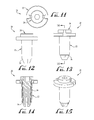
- FIG. 11 is a perspective top view of the snap lock inner and outer pieces after being snapped into place
- FIG. 12 is a perspective side view of the snap lock inner and outer pieces after being snapped into place and demonstrating the view of the slot of the inner piece;
- FIG. 13 is a perspective side view of the snap lock inner and outer pieces after being snapped into place and demonstrating the non-slotted inner piece;
- FIG. 14 is a perspective cross sectional side view of the snap lock inner and outer pieces after being snapped into place
- FIG. 15 is a perspective top side view of the snap lock inner and outer pieces after being snapped into place
- FIG. 16 is a perspective top view of the snap lock after passage of suture material and after the inner and outer pieces are snapped into place;
- FIG. 17 is a perspective side view of the snap lock after passage of suture material and after the inner and outer pieces are snapped into place demonstrating the slotted side of the inner piece;
- FIG. 18 is a perspective side view of the snap lock after passage of suture material and after the inner and outer pieces are snapped into place demonstrating the non-slotted side of the inner piece;
- FIG. 19 is a perspective cross sectional side view of the snap lock after passage of suture material and after the inner and outer pieces are snapped into place;
- FIG. 20 is a top side view of the snap lock after passage of suture material and after the inner and outer pieces are snapped into place;
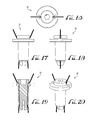
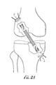
- FIG. 21 is a drawing demonstrating application of the snap lock fixation device for fixation of anterior cruciate ligament reconstruction
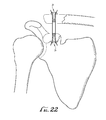
- FIG. 22 is a drawing demonstrating application of the snap lock fixation device for fixation of an acromial clavicular joint dislocation
- FIG. 23 is an exploded, perspective view of a preferred embodiment of an insertion instrument or tool for use with the FIGS. 1-22 embodiment.
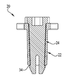
- FIG. 24 is a side, cross-sectional view of the FIG. 23 insertion tool embodiment.
- embodiments of the presently described snap lock 20 includes an outer piece hollow, shell 22 as illustrated in FIGS. 1-5 , and an inner piece 24 as illustrated in FIGS. 6-10 .
- the shell 22 is also referred to as a body, is generally of a hollow, cylindrical configuration, preferably with its inner diameter tapered or narrowed from the top down to the bottom.
- the shell 22 is inserted into a pre-drilled hole within bone.
- the shell 22 includes a hollowed, tapered shaft, or canal 26 , having a predetermined inner diameter and extending downward from a wider diameter collar or top flange 28 .
- the shell 22 is preferably of a one-piece construction, as shown in FIG. 5 .
- the outer of the shell i.e., the surfaces at the outer diameter, may be smooth, roughened or screw shaped with a threaded, tapered pitch.
- Canal 26 is adapted and sized to snuggly receive a tapered shaft 28 part of the inner piece or component 24 as shown by arrow 30 in FIG. 5 .
- the inner piece 24 is advanced or inserted into canal 26 of the outer piece 22 , preferably by an inserter instrument as illustrated in FIGS. 23-24 .
- the distal end of the inner piece 24 includes, preferably, a slotted tip 30 , which functions to permit squeezing and narrowing of the diameter of the distal end during insertion.
- the tip 30 of the inner piece narrows to allow passage and then returns, or snaps back to its original position outside of the distal end of the outer piece. This snapping action locks the two components together, as shown in FIGS. 11-15 . Referring to FIGS.
- the inner piece distal end, at tip 30 has a rigid slight prominence or radially outwardly protruding shoulder 32 that hooks or snaps outwardly onto the tip 34 of outer piece 22 , as shown in Figures 12 - 15 .
- the shoulder 32 prevents the inner piece 24 from retracting backwards and separating from the outer piece 22 .
- the outer and inner pieces 22 , 24 respectively may be made of various types of materials that have the ability to provide a secure fastening and to provide the snapping functionality as described herein.
- the materials of construction can include PEEK, composite, or metal.
- the outer and inner pieces may also have a smooth or roughened surface or of a smooth or rough-surfaced material.
- inventions of the invention involve passing sutures through the tip of the distal end of the outer piece (shell) and up through the central canal of the outer piece (shell) and out the top of the outer piece (shell).
- the inner piece or tapered, cylindrical plug is then advanced into the outer piece until fully seated and locks into place as the tip of the inner piece returns or snaps and locks into its original position, with the projection of the tip of the inner piece extending radially outward or beyond outer diameter of the outer piece.
- This snap locking function compresses the sutures at the distal end tip of the outer piece (shell) and also against the inner walls of the outer piece.
- the presently preferred internal snap-in mechanism shown and described herein provides for multiple points of fixation of variously sized (thickness and width) suture material. This allows for optimal positioning of the ligament reconstruction. For example, if the fixture device is used on both sides of the knee for an ACL reconstruction, the tissue graft can be advanced into the femur or tibia and adjusted from either end of the graft, as shown in Figure. This exemplary way of fixation may avoid a significant problem known to be associated with bone tendon bone reconstructions, and commonly referred to as “tunnel mismatch.”
- the presently described fixation lock and method of implementation also permits performing these types of reconstructions without the need for fixation of the tissue within the socket (such as with interference screws).
- the collar portion 28 of the body or shell also can function to plug the hole preventing leakage of important fluids involved in the ligament healing process.
- the presently described snap lock also functions to permit fixation of tissue through small incisions which in turn avoids further soft tissue damage associated with more invasive exposures.
- Another exemplary application is for use in the shoulder for reconstruction of the ligaments following an acromial clavicular dislocation, as shown in FIG. 22 .
- the present snap lock may be developed with slight variations of the internal or outer components for the same multiple point fixation.
- the present snap lock may be used in various areas of the body such as the knee, shoulder, ankle, and hip for stabilization of joints with ligament laxity.
Landscapes
- Health & Medical Sciences (AREA)
- Surgery (AREA)
- Life Sciences & Earth Sciences (AREA)
- Biomedical Technology (AREA)
- Nuclear Medicine, Radiotherapy & Molecular Imaging (AREA)
- Engineering & Computer Science (AREA)
- Heart & Thoracic Surgery (AREA)
- Medical Informatics (AREA)
- Molecular Biology (AREA)
- Animal Behavior & Ethology (AREA)
- General Health & Medical Sciences (AREA)
- Public Health (AREA)
- Veterinary Medicine (AREA)
- Rheumatology (AREA)
- Surgical Instruments (AREA)
Abstract
Description
- The invention relates generally to the field of surgery and is intended to allow for improved fixation of soft tissue to bone.
- Devices and methods of suspending suture(s) from bone are known. However, these devices and methods typically require knotting the suture(s), and expose the suspended suture(s) to loosening and/or untying.
- The snap lock and method of implementation according to the present invention overcome the drawbacks of known suture lock devices and methods of implementation by providing multiple points of fixation of the suture and without knotting the suture.
- This invention relates to an apparatus and method for suspending suture from bone and providing a secure fixation of the suture within the device. The specific design of the device allows for tensioning of various sized suture material or suture tape that has been passed through the device. After the sutures are pulled through the apparatus member to the desired position of fixation, a second internal member of the apparatus is advanced and snapped into the apparatus which provides for multiple points of fixation against the suture. The unique internal compression mechanism allows for three different points of compression against the suture material which allows for superior fixation. Embodiments of the presently described snap lock accomplish knotless fixation of soft tissue to bone.
- The present snap lock is intended to be used in the reconstruction of soft tissue disruption such as ligament or tendon tears. This lock and its implementation avoid the need for suture tying and are intended for use in various areas of the musculoskeletal system. By providing secure fixation of the tissue within the bone, the body part may be rehabilitated more aggressively and thereby reducing postoperative complications such as stiffness of a joint and improve recovery time following surgery.
- Implementation of the present snap lock includes drilling or reaming a desired size hole into bone. Sutures are then passed through the hole and then passed through the lock. The lock is then inserted into the hole and pressed against the bone. The sutures are then pulled through the lock to the desired tension. The tissue intended for fixation has already been attached to the opposite end of the sutures. Once satisfactory positioning of the tissue is achieved, the snap lock is operated or tightened by advancing the internal piece which snaps into place when fully seated into the outer piece. This locks and compresses the sutures against the inner wall of the outer piece. This allows for completion of the ligament fixation.
- The present invention allows for fastening of suture through a predrilled hole by compression of the suture between pieces of the apparatus. Prior to passing the suture through the device, it is attached to tissue (such as ligament, tendon, or bone) that is intended to be “fixed”.
- These and other embodiments, features, aspects, and advantages of the invention will become better understood with regard to the following description, appended claims and accompanying drawings.
- The foregoing aspects and the attendant advantages of the present invention will become more readily appreciated by reference to the following detailed description, when taken in conjunction with the accompanying drawings, wherein:
-
FIG. 1 is a perspective top view of a preferred embodiment snap lock outer piece; -
FIG. 2 is a perspective top side view of the snap lock outer piece; -
FIG. 3 is a perspective side view of the snap lock outer piece with a view of the anti-rotational slot; -
FIG. 4 is a perspective side view of the snap lock outer piece of the side without the anti-rotational slot; -
FIG. 5 is a perspective cross section side view of the snap lock outer piece of the inside of the outer piece demonstrating the tapered inner portion; -
FIG. 6 is a perspective top view of the snap lock inner piece; -
FIG. 7 is a perspective side view of the snap lock inner piece demonstrating the distal slot intended for narrowing of the piece as it is advanced into the outer piece; and the outward protruding shoulder allowing for the “locking” mechanism after the inner piece is fully seated into the outer piece; -
FIG. 8 is a perspective side view of the snap lock inner piece on the side that is not slotted distally; -
FIG. 9 is a perspective cross section side view of the inner piece; -
FIG. 10 is a perspective top side view of the snap lock inner piece; -
FIG. 11 is a perspective top view of the snap lock inner and outer pieces after being snapped into place; -
FIG. 12 is a perspective side view of the snap lock inner and outer pieces after being snapped into place and demonstrating the view of the slot of the inner piece; -
FIG. 13 is a perspective side view of the snap lock inner and outer pieces after being snapped into place and demonstrating the non-slotted inner piece; -
FIG. 14 is a perspective cross sectional side view of the snap lock inner and outer pieces after being snapped into place; -
FIG. 15 is a perspective top side view of the snap lock inner and outer pieces after being snapped into place; -
FIG. 16 is a perspective top view of the snap lock after passage of suture material and after the inner and outer pieces are snapped into place; -
FIG. 17 is a perspective side view of the snap lock after passage of suture material and after the inner and outer pieces are snapped into place demonstrating the slotted side of the inner piece; -
FIG. 18 is a perspective side view of the snap lock after passage of suture material and after the inner and outer pieces are snapped into place demonstrating the non-slotted side of the inner piece; -
FIG. 19 is a perspective cross sectional side view of the snap lock after passage of suture material and after the inner and outer pieces are snapped into place; -
FIG. 20 is a top side view of the snap lock after passage of suture material and after the inner and outer pieces are snapped into place; -
FIG. 21 is a drawing demonstrating application of the snap lock fixation device for fixation of anterior cruciate ligament reconstruction; -
FIG. 22 is a drawing demonstrating application of the snap lock fixation device for fixation of an acromial clavicular joint dislocation; -
FIG. 23 is an exploded, perspective view of a preferred embodiment of an insertion instrument or tool for use with theFIGS. 1-22 embodiment; and, -
FIG. 24 is a side, cross-sectional view of theFIG. 23 insertion tool embodiment. - In accordance with embodiments described herein, embodiments of the presently described
snap lock 20, illustrated inFIGS. 11-15 , includes an outer piece hollow,shell 22 as illustrated inFIGS. 1-5 , and aninner piece 24 as illustrated inFIGS. 6-10 . Theshell 22 is also referred to as a body, is generally of a hollow, cylindrical configuration, preferably with its inner diameter tapered or narrowed from the top down to the bottom. During a surgical procedure, as illustrated inFIGS. 21-22 , theshell 22 is inserted into a pre-drilled hole within bone. Theshell 22 includes a hollowed, tapered shaft, orcanal 26, having a predetermined inner diameter and extending downward from a wider diameter collar ortop flange 28. Theshell 22 is preferably of a one-piece construction, as shown inFIG. 5 . The outer of the shell, i.e., the surfaces at the outer diameter, may be smooth, roughened or screw shaped with a threaded, tapered pitch. - Canal 26 is adapted and sized to snuggly receive a
tapered shaft 28 part of the inner piece orcomponent 24 as shown byarrow 30 inFIG. 5 . - During a surgical procedure, the
inner piece 24 is advanced or inserted intocanal 26 of theouter piece 22, preferably by an inserter instrument as illustrated inFIGS. 23-24 . As shown inFIGS. 7, 9 and 10 , the distal end of theinner piece 24 includes, preferably, a slottedtip 30, which functions to permit squeezing and narrowing of the diameter of the distal end during insertion. As the distal end ofinner piece 24 is advanced toward and beyond the distal end of theouter piece 22, thetip 30 of the inner piece narrows to allow passage and then returns, or snaps back to its original position outside of the distal end of the outer piece. This snapping action locks the two components together, as shown inFIGS. 11-15 . Referring toFIGS. 7-10 , the inner piece distal end, attip 30 has a rigid slight prominence or radially outwardly protrudingshoulder 32 that hooks or snaps outwardly onto thetip 34 ofouter piece 22, as shown in Figures12-15. Once fully advanced and snapped into place, theshoulder 32 prevents theinner piece 24 from retracting backwards and separating from theouter piece 22. The outer andinner pieces - The clinical application of embodiments of the invention involves passing sutures through the tip of the distal end of the outer piece (shell) and up through the central canal of the outer piece (shell) and out the top of the outer piece (shell). The inner piece or tapered, cylindrical plug is then advanced into the outer piece until fully seated and locks into place as the tip of the inner piece returns or snaps and locks into its original position, with the projection of the tip of the inner piece extending radially outward or beyond outer diameter of the outer piece. This snap locking function compresses the sutures at the distal end tip of the outer piece (shell) and also against the inner walls of the outer piece. Finally, when the inner piece is advanced completely, it's “head or top flange or
collar 28 engages and presses the sutures against the outer rim of the top, or proximal end of the outer piece (shell) to provide a third area of compression/fixation as shown inFIGS. 16-20 . This multiple-point compression of the suture material between the two pieces or components of the snap lock provides optimal knotless fixation. - The presently preferred internal snap-in mechanism shown and described herein provides for multiple points of fixation of variously sized (thickness and width) suture material. This allows for optimal positioning of the ligament reconstruction. For example, if the fixture device is used on both sides of the knee for an ACL reconstruction, the tissue graft can be advanced into the femur or tibia and adjusted from either end of the graft, as shown in Figure. This exemplary way of fixation may avoid a significant problem known to be associated with bone tendon bone reconstructions, and commonly referred to as “tunnel mismatch.” The presently described fixation lock and method of implementation also permits performing these types of reconstructions without the need for fixation of the tissue within the socket (such as with interference screws). The
collar portion 28 of the body or shell also can function to plug the hole preventing leakage of important fluids involved in the ligament healing process. The presently described snap lock also functions to permit fixation of tissue through small incisions which in turn avoids further soft tissue damage associated with more invasive exposures. Another exemplary application is for use in the shoulder for reconstruction of the ligaments following an acromial clavicular dislocation, as shown inFIG. 22 . - The present snap lock may be developed with slight variations of the internal or outer components for the same multiple point fixation.
- The present snap lock may be used in various areas of the body such as the knee, shoulder, ankle, and hip for stabilization of joints with ligament laxity.
- Although specific embodiments of the invention have been described, various modifications, alterations, alternative constructions, and equivalents are also encompassed within the scope of the invention.
- The specification and drawings are, accordingly, to be regarded in an illustrative rather than a restrictive sense. It will, however, be evident that additions, subtractions, deletions, and other modifications and changes may be made thereunto without departing from the broader spirit and scope of the invention as set forth in the claims.
Claims (2)
Priority Applications (1)
| Application Number | Priority Date | Filing Date | Title |
|---|---|---|---|
| US15/729,054 US11284874B2 (en) | 2016-10-11 | 2017-10-10 | Snap lock |
Applications Claiming Priority (2)
| Application Number | Priority Date | Filing Date | Title |
|---|---|---|---|
| US201662406656P | 2016-10-11 | 2016-10-11 | |
| US15/729,054 US11284874B2 (en) | 2016-10-11 | 2017-10-10 | Snap lock |
Publications (2)
| Publication Number | Publication Date |
|---|---|
| US20180098762A1 true US20180098762A1 (en) | 2018-04-12 |
| US11284874B2 US11284874B2 (en) | 2022-03-29 |
Family
ID=61830327
Family Applications (1)
| Application Number | Title | Priority Date | Filing Date |
|---|---|---|---|
| US15/729,054 Active 2038-03-31 US11284874B2 (en) | 2016-10-11 | 2017-10-10 | Snap lock |
Country Status (1)
| Country | Link |
|---|---|
| US (1) | US11284874B2 (en) |
Cited By (5)
| Publication number | Priority date | Publication date | Assignee | Title |
|---|---|---|---|---|
| US20200289109A1 (en) * | 2019-03-12 | 2020-09-17 | Dunamis, LLC | Knotless orthopedic stabilization system |
| FR3095329A1 (en) * | 2019-04-29 | 2020-10-30 | Novastep | Surgical implant for plantar plate repair |
| WO2024240871A1 (en) * | 2023-05-24 | 2024-11-28 | Novetech Surgery S.A.R.L. | Fastening system and fastening kit for ligamentoplasty |
| US12383322B2 (en) * | 2023-08-22 | 2025-08-12 | DePuy Synthes Products, Inc. | Methods and devices for syndesmosis tensioning |
| USD1092739S1 (en) * | 2023-03-03 | 2025-09-09 | Abanza Tecnomed, S.L. | Medical implant |
Citations (3)
| Publication number | Priority date | Publication date | Assignee | Title |
|---|---|---|---|---|
| US20060235410A1 (en) * | 2005-04-15 | 2006-10-19 | Ralph James D | Surgical expansion fasteners |
| US20090292321A1 (en) * | 2006-06-23 | 2009-11-26 | Michel Collette | Bone anchoring device |
| US20110046682A1 (en) * | 2009-07-06 | 2011-02-24 | Synthes Gmbh Or Synthes Usa, Llc | Expandable fixation assemblies |
Family Cites Families (5)
| Publication number | Priority date | Publication date | Assignee | Title |
|---|---|---|---|---|
| US7517357B2 (en) * | 2003-01-09 | 2009-04-14 | Linvatec Biomaterials | Knotless suture anchor |
| US20100262185A1 (en) | 2009-04-10 | 2010-10-14 | Suspension Orthopaedic Solutions, Llc | Method and apparatus for aperture fixation by securing flexible material with a knotless fixation device |
| US9144425B2 (en) | 2012-10-03 | 2015-09-29 | Lee D. Kaplan | Suture for soft tissue repair |
| US10076377B2 (en) * | 2013-01-05 | 2018-09-18 | P Tech, Llc | Fixation systems and methods |
| US10631845B2 (en) | 2016-01-22 | 2020-04-28 | Arthrex, Inc. | Tensionable knotless anchors and methods of tissue repair |
-
2017
- 2017-10-10 US US15/729,054 patent/US11284874B2/en active Active
Patent Citations (3)
| Publication number | Priority date | Publication date | Assignee | Title |
|---|---|---|---|---|
| US20060235410A1 (en) * | 2005-04-15 | 2006-10-19 | Ralph James D | Surgical expansion fasteners |
| US20090292321A1 (en) * | 2006-06-23 | 2009-11-26 | Michel Collette | Bone anchoring device |
| US20110046682A1 (en) * | 2009-07-06 | 2011-02-24 | Synthes Gmbh Or Synthes Usa, Llc | Expandable fixation assemblies |
Cited By (8)
| Publication number | Priority date | Publication date | Assignee | Title |
|---|---|---|---|---|
| US20200289109A1 (en) * | 2019-03-12 | 2020-09-17 | Dunamis, LLC | Knotless orthopedic stabilization system |
| FR3095329A1 (en) * | 2019-04-29 | 2020-10-30 | Novastep | Surgical implant for plantar plate repair |
| USD1092739S1 (en) * | 2023-03-03 | 2025-09-09 | Abanza Tecnomed, S.L. | Medical implant |
| USD1095839S1 (en) * | 2023-03-03 | 2025-09-30 | Abanza Tecnomed, S.L. | Medical implant |
| USD1097157S1 (en) * | 2023-03-03 | 2025-10-07 | Abanza Tecnomed, S.L. | Medical implant |
| WO2024240871A1 (en) * | 2023-05-24 | 2024-11-28 | Novetech Surgery S.A.R.L. | Fastening system and fastening kit for ligamentoplasty |
| FR3148905A1 (en) * | 2023-05-24 | 2024-11-29 | Novetech Surgery S.A.R.L. | Fixation system and fixation kit for ligament reconstruction |
| US12383322B2 (en) * | 2023-08-22 | 2025-08-12 | DePuy Synthes Products, Inc. | Methods and devices for syndesmosis tensioning |
Also Published As
| Publication number | Publication date |
|---|---|
| US11284874B2 (en) | 2022-03-29 |
Similar Documents
| Publication | Publication Date | Title |
|---|---|---|
| US12403000B2 (en) | Ligament fixation device and method | |
| US20220395268A1 (en) | System and method for securing tissue to bone | |
| US20160228117A1 (en) | Suture lock | |
| US11284874B2 (en) | Snap lock | |
| US10542967B2 (en) | Method and apparatus for coupling soft tissue to a bone | |
| US9408599B2 (en) | Method and apparatus for coupling soft tissue to a bone | |
| US20070225805A1 (en) | Ligament Fixation Using Graft Harness/Bolt Assembly | |
| US9681865B2 (en) | Tissue graft fixation | |
| US12251093B2 (en) | Method and apparatus for coupling soft tissue to a bone | |
| US6264694B1 (en) | Soft tissue graft fixation device and method | |
| JP6561040B2 (en) | System and method for securing tissue to bone | |
| US20130090731A1 (en) | Ligament Retainer Device and Method | |
| US9044314B2 (en) | Method and device for the fixation of a tendon graft | |
| CN103702629B (en) | Method soft tissue graft thing being fastened in the hole on people's bone or Animal Bone and the retention mechanism suitable for this method | |
| US20080288069A1 (en) | Threaded pulley anchor apparatus and method for use in surgical repair of ligament or tendon | |
| JP2019528877A (en) | Orthopedic bone anchor suspension device | |
| US20250268704A1 (en) | Zip-tie systems for ligament and tendon repair and replacement | |
| US20250064444A1 (en) | Self-cinching suture devices and methods |
Legal Events
| Date | Code | Title | Description |
|---|---|---|---|
| FEPP | Fee payment procedure |
Free format text: ENTITY STATUS SET TO UNDISCOUNTED (ORIGINAL EVENT CODE: BIG.); ENTITY STATUS OF PATENT OWNER: SMALL ENTITY |
|
| FEPP | Fee payment procedure |
Free format text: ENTITY STATUS SET TO SMALL (ORIGINAL EVENT CODE: SMAL); ENTITY STATUS OF PATENT OWNER: SMALL ENTITY |
|
| STPP | Information on status: patent application and granting procedure in general |
Free format text: DOCKETED NEW CASE - READY FOR EXAMINATION |
|
| STPP | Information on status: patent application and granting procedure in general |
Free format text: NON FINAL ACTION MAILED |
|
| STPP | Information on status: patent application and granting procedure in general |
Free format text: RESPONSE TO NON-FINAL OFFICE ACTION ENTERED AND FORWARDED TO EXAMINER |
|
| STPP | Information on status: patent application and granting procedure in general |
Free format text: FINAL REJECTION MAILED |
|
| STPP | Information on status: patent application and granting procedure in general |
Free format text: DOCKETED NEW CASE - READY FOR EXAMINATION |
|
| STPP | Information on status: patent application and granting procedure in general |
Free format text: PUBLICATIONS -- ISSUE FEE PAYMENT VERIFIED |
|
| STCF | Information on status: patent grant |
Free format text: PATENTED CASE |
|
| FEPP | Fee payment procedure |
Free format text: SURCHARGE FOR LATE PAYMENT, SMALL ENTITY (ORIGINAL EVENT CODE: M2554); ENTITY STATUS OF PATENT OWNER: SMALL ENTITY |
|
| MAFP | Maintenance fee payment |
Free format text: PAYMENT OF MAINTENANCE FEE, 4TH YR, SMALL ENTITY (ORIGINAL EVENT CODE: M2551); ENTITY STATUS OF PATENT OWNER: SMALL ENTITY Year of fee payment: 4 |