US20180098751A1 - Ultrasound system control panel and display lift - Google Patents
Ultrasound system control panel and display lift Download PDFInfo
- Publication number
- US20180098751A1 US20180098751A1 US15/835,535 US201715835535A US2018098751A1 US 20180098751 A1 US20180098751 A1 US 20180098751A1 US 201715835535 A US201715835535 A US 201715835535A US 2018098751 A1 US2018098751 A1 US 2018098751A1
- Authority
- US
- United States
- Prior art keywords
- control panel
- display
- pivot
- lift
- coupled
- Prior art date
- Legal status (The legal status is an assumption and is not a legal conclusion. Google has not performed a legal analysis and makes no representation as to the accuracy of the status listed.)
- Granted
Links
Images

Classifications
-
- A—HUMAN NECESSITIES
- A61—MEDICAL OR VETERINARY SCIENCE; HYGIENE
- A61B—DIAGNOSIS; SURGERY; IDENTIFICATION
- A61B8/00—Diagnosis using ultrasonic, sonic or infrasonic waves
- A61B8/46—Ultrasonic, sonic or infrasonic diagnostic devices with special arrangements for interfacing with the operator or the patient
- A61B8/461—Displaying means of special interest
- A61B8/462—Displaying means of special interest characterised by constructional features of the display
-
- A—HUMAN NECESSITIES
- A61—MEDICAL OR VETERINARY SCIENCE; HYGIENE
- A61B—DIAGNOSIS; SURGERY; IDENTIFICATION
- A61B8/00—Diagnosis using ultrasonic, sonic or infrasonic waves
- A61B8/44—Constructional features of the ultrasonic, sonic or infrasonic diagnostic device
- A61B8/4405—Device being mounted on a trolley
-
- A—HUMAN NECESSITIES
- A61—MEDICAL OR VETERINARY SCIENCE; HYGIENE
- A61B—DIAGNOSIS; SURGERY; IDENTIFICATION
- A61B8/00—Diagnosis using ultrasonic, sonic or infrasonic waves
- A61B8/46—Ultrasonic, sonic or infrasonic diagnostic devices with special arrangements for interfacing with the operator or the patient
- A61B8/467—Ultrasonic, sonic or infrasonic diagnostic devices with special arrangements for interfacing with the operator or the patient characterised by special input means
-
- F—MECHANICAL ENGINEERING; LIGHTING; HEATING; WEAPONS; BLASTING
- F16—ENGINEERING ELEMENTS AND UNITS; GENERAL MEASURES FOR PRODUCING AND MAINTAINING EFFECTIVE FUNCTIONING OF MACHINES OR INSTALLATIONS; THERMAL INSULATION IN GENERAL
- F16M—FRAMES, CASINGS OR BEDS OF ENGINES, MACHINES OR APPARATUS, NOT SPECIFIC TO ENGINES, MACHINES OR APPARATUS PROVIDED FOR ELSEWHERE; STANDS; SUPPORTS
- F16M11/00—Stands or trestles as supports for apparatus or articles placed thereon ; Stands for scientific apparatus such as gravitational force meters
- F16M11/02—Heads
- F16M11/04—Means for attachment of apparatus; Means allowing adjustment of the apparatus relatively to the stand
- F16M11/043—Allowing translations
- F16M11/046—Allowing translations adapted to upward-downward translation movement
-
- F—MECHANICAL ENGINEERING; LIGHTING; HEATING; WEAPONS; BLASTING
- F16—ENGINEERING ELEMENTS AND UNITS; GENERAL MEASURES FOR PRODUCING AND MAINTAINING EFFECTIVE FUNCTIONING OF MACHINES OR INSTALLATIONS; THERMAL INSULATION IN GENERAL
- F16M—FRAMES, CASINGS OR BEDS OF ENGINES, MACHINES OR APPARATUS, NOT SPECIFIC TO ENGINES, MACHINES OR APPARATUS PROVIDED FOR ELSEWHERE; STANDS; SUPPORTS
- F16M11/00—Stands or trestles as supports for apparatus or articles placed thereon ; Stands for scientific apparatus such as gravitational force meters
- F16M11/02—Heads
- F16M11/04—Means for attachment of apparatus; Means allowing adjustment of the apparatus relatively to the stand
- F16M11/06—Means for attachment of apparatus; Means allowing adjustment of the apparatus relatively to the stand allowing pivoting
- F16M11/10—Means for attachment of apparatus; Means allowing adjustment of the apparatus relatively to the stand allowing pivoting around a horizontal axis
-
- F—MECHANICAL ENGINEERING; LIGHTING; HEATING; WEAPONS; BLASTING
- F16—ENGINEERING ELEMENTS AND UNITS; GENERAL MEASURES FOR PRODUCING AND MAINTAINING EFFECTIVE FUNCTIONING OF MACHINES OR INSTALLATIONS; THERMAL INSULATION IN GENERAL
- F16M—FRAMES, CASINGS OR BEDS OF ENGINES, MACHINES OR APPARATUS, NOT SPECIFIC TO ENGINES, MACHINES OR APPARATUS PROVIDED FOR ELSEWHERE; STANDS; SUPPORTS
- F16M11/00—Stands or trestles as supports for apparatus or articles placed thereon ; Stands for scientific apparatus such as gravitational force meters
- F16M11/02—Heads
- F16M11/04—Means for attachment of apparatus; Means allowing adjustment of the apparatus relatively to the stand
- F16M11/06—Means for attachment of apparatus; Means allowing adjustment of the apparatus relatively to the stand allowing pivoting
- F16M11/12—Means for attachment of apparatus; Means allowing adjustment of the apparatus relatively to the stand allowing pivoting in more than one direction
-
- F—MECHANICAL ENGINEERING; LIGHTING; HEATING; WEAPONS; BLASTING
- F16—ENGINEERING ELEMENTS AND UNITS; GENERAL MEASURES FOR PRODUCING AND MAINTAINING EFFECTIVE FUNCTIONING OF MACHINES OR INSTALLATIONS; THERMAL INSULATION IN GENERAL
- F16M—FRAMES, CASINGS OR BEDS OF ENGINES, MACHINES OR APPARATUS, NOT SPECIFIC TO ENGINES, MACHINES OR APPARATUS PROVIDED FOR ELSEWHERE; STANDS; SUPPORTS
- F16M11/00—Stands or trestles as supports for apparatus or articles placed thereon ; Stands for scientific apparatus such as gravitational force meters
- F16M11/20—Undercarriages with or without wheels
- F16M11/2007—Undercarriages with or without wheels comprising means allowing pivoting adjustment
- F16M11/2014—Undercarriages with or without wheels comprising means allowing pivoting adjustment around a vertical axis
-
- F—MECHANICAL ENGINEERING; LIGHTING; HEATING; WEAPONS; BLASTING
- F16—ENGINEERING ELEMENTS AND UNITS; GENERAL MEASURES FOR PRODUCING AND MAINTAINING EFFECTIVE FUNCTIONING OF MACHINES OR INSTALLATIONS; THERMAL INSULATION IN GENERAL
- F16M—FRAMES, CASINGS OR BEDS OF ENGINES, MACHINES OR APPARATUS, NOT SPECIFIC TO ENGINES, MACHINES OR APPARATUS PROVIDED FOR ELSEWHERE; STANDS; SUPPORTS
- F16M11/00—Stands or trestles as supports for apparatus or articles placed thereon ; Stands for scientific apparatus such as gravitational force meters
- F16M11/20—Undercarriages with or without wheels
- F16M11/2007—Undercarriages with or without wheels comprising means allowing pivoting adjustment
- F16M11/2035—Undercarriages with or without wheels comprising means allowing pivoting adjustment in more than one direction
- F16M11/2064—Undercarriages with or without wheels comprising means allowing pivoting adjustment in more than one direction for tilting and panning
-
- F—MECHANICAL ENGINEERING; LIGHTING; HEATING; WEAPONS; BLASTING
- F16—ENGINEERING ELEMENTS AND UNITS; GENERAL MEASURES FOR PRODUCING AND MAINTAINING EFFECTIVE FUNCTIONING OF MACHINES OR INSTALLATIONS; THERMAL INSULATION IN GENERAL
- F16M—FRAMES, CASINGS OR BEDS OF ENGINES, MACHINES OR APPARATUS, NOT SPECIFIC TO ENGINES, MACHINES OR APPARATUS PROVIDED FOR ELSEWHERE; STANDS; SUPPORTS
- F16M11/00—Stands or trestles as supports for apparatus or articles placed thereon ; Stands for scientific apparatus such as gravitational force meters
- F16M11/20—Undercarriages with or without wheels
- F16M11/24—Undercarriages with or without wheels changeable in height or length of legs, also for transport only, e.g. by means of tubes screwed into each other
-
- H—ELECTRICITY
- H01—ELECTRIC ELEMENTS
- H01H—ELECTRIC SWITCHES; RELAYS; SELECTORS; EMERGENCY PROTECTIVE DEVICES
- H01H3/00—Mechanisms for operating contacts
- H01H3/02—Operating parts, i.e. for operating driving mechanism by a mechanical force external to the switch
- H01H3/12—Push-buttons
-
- H—ELECTRICITY
- H01—ELECTRIC ELEMENTS
- H01H—ELECTRIC SWITCHES; RELAYS; SELECTORS; EMERGENCY PROTECTIVE DEVICES
- H01H3/00—Mechanisms for operating contacts
- H01H3/02—Operating parts, i.e. for operating driving mechanism by a mechanical force external to the switch
- H01H3/14—Operating parts, i.e. for operating driving mechanism by a mechanical force external to the switch adapted for operation by a part of the human body other than the hand, e.g. by foot
-
- H—ELECTRICITY
- H01—ELECTRIC ELEMENTS
- H01H—ELECTRIC SWITCHES; RELAYS; SELECTORS; EMERGENCY PROTECTIVE DEVICES
- H01H9/00—Details of switching devices, not covered by groups H01H1/00 - H01H7/00
- H01H9/16—Indicators for switching condition, e.g. "on" or "off"
- H01H9/161—Indicators for switching condition, e.g. "on" or "off" comprising light emitting elements
-
- H—ELECTRICITY
- H01—ELECTRIC ELEMENTS
- H01H—ELECTRIC SWITCHES; RELAYS; SELECTORS; EMERGENCY PROTECTIVE DEVICES
- H01H9/00—Details of switching devices, not covered by groups H01H1/00 - H01H7/00
- H01H9/20—Interlocking, locking, or latching mechanisms
- H01H9/26—Interlocking, locking, or latching mechanisms for interlocking two or more switches
-
- H—ELECTRICITY
- H05—ELECTRIC TECHNIQUES NOT OTHERWISE PROVIDED FOR
- H05K—PRINTED CIRCUITS; CASINGS OR CONSTRUCTIONAL DETAILS OF ELECTRIC APPARATUS; MANUFACTURE OF ASSEMBLAGES OF ELECTRICAL COMPONENTS
- H05K5/00—Casings, cabinets or drawers for electric apparatus
- H05K5/0017—Casings, cabinets or drawers for electric apparatus with operator interface units
-
- F—MECHANICAL ENGINEERING; LIGHTING; HEATING; WEAPONS; BLASTING
- F16—ENGINEERING ELEMENTS AND UNITS; GENERAL MEASURES FOR PRODUCING AND MAINTAINING EFFECTIVE FUNCTIONING OF MACHINES OR INSTALLATIONS; THERMAL INSULATION IN GENERAL
- F16M—FRAMES, CASINGS OR BEDS OF ENGINES, MACHINES OR APPARATUS, NOT SPECIFIC TO ENGINES, MACHINES OR APPARATUS PROVIDED FOR ELSEWHERE; STANDS; SUPPORTS
- F16M2200/00—Details of stands or supports
- F16M2200/02—Locking means
- F16M2200/021—Locking means for rotational movement
- F16M2200/024—Locking means for rotational movement by positive interaction, e.g. male-female connections
-
- F—MECHANICAL ENGINEERING; LIGHTING; HEATING; WEAPONS; BLASTING
- F16—ENGINEERING ELEMENTS AND UNITS; GENERAL MEASURES FOR PRODUCING AND MAINTAINING EFFECTIVE FUNCTIONING OF MACHINES OR INSTALLATIONS; THERMAL INSULATION IN GENERAL
- F16M—FRAMES, CASINGS OR BEDS OF ENGINES, MACHINES OR APPARATUS, NOT SPECIFIC TO ENGINES, MACHINES OR APPARATUS PROVIDED FOR ELSEWHERE; STANDS; SUPPORTS
- F16M2200/00—Details of stands or supports
- F16M2200/04—Balancing means
- F16M2200/041—Balancing means for balancing rotational movement of the head
Definitions
- This invention relates to medical diagnostic ultrasound systems and, in particular, to ultrasound system carts with adjustable control panel and display elevation.
- Cart-borne ultrasound systems are convenient medical imaging instruments because they can be set up easily in an imaging lab or rolled to a patient's bedside when needed. They are conventionally used by sonographers in different postures: standing, sitting or leaning over the patient being scanned. In any of these positions it is important to position the control panel in a so-called “user zone” for the sonographer so that it is comfortably accessible and enables easy manipulation of the display screen so that it can closely observed while scanning. In order to make these adjustments it is necessary for the control panel and system display to have a wide range of motion, both horizontally and vertically. After the control panel and display are properly positioned, the control panel must remain solidly in place and not move or wobble as the sonographer manipulates the controls. The present invention is directed to meeting these objectives.
- a lift for an ultrasound system which enables the control panel and display to be elevated to different heights and pivoted to a comfortable position for the sonographer.
- the lift allows the control panel to be positioned manually with a handle on the control panel, with the weight of the control panel offset by a hydraulic strut in the lift.
- the lift contains a four-bar linkage which maintains the inclination of the control panel as it is elevated and/or rotated.
- the hydraulic strut and pivot axis are locked by solenoids to maintain the control panel solidly in position.
- the lift is locked while the cart is wheeled to a different position or location.
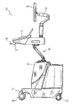
- FIG. 1 illustrates a cart-borne ultrasound system constructed in accordance with the principles of the present invention.
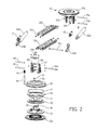
- FIG. 2 illustrates an exploded view of a control panel lift for an ultrasound system of the present invention.
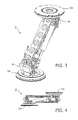
- FIG. 3 is a perspective view of the assembled control panel lift of FIG. 2 .
- FIG. 4 illustrates the control panel lift of FIG. 3 in its fully folded position.
- a cart-borne ultrasound system 10 is shown.
- the base of the cart is a housing 12 containing the electronics of the ultrasound system such as printed circuit boards.
- At the back of the housing is a compartment in which accessories such as probes, video recorders, gel bottles and cables may be stored or installed.
- the cart has wheels 20 so that the cart can be rolled to where it is needed.
- a brake pedal 22 which a user can depress the lock the wheels so that the cart will not roll or move after it has been positioned for an exam.
- a control panel 14 by which a sonographer operates the ultrasound system and controls a scanning procedure.
- a display screen 16 is mounted above the control panel where the sonographer can observe the screen while manipulating the controls of the control panel or scanning the patient.
- the display screen is mounted at the end of an articulating arm 18 which allows the screen to be raised, lowered, tilted, and moved or turned to the left or right so as to locate the screen in a convenient position for observation while scanning.
- the articulating arm is more fully described in US pat. pub. no. US 2008/0234577 (Murkowski et al.)
- the control panel 14 and display 16 are attached to the top of a lift 30 which is mounted on the cart housing 12 .
- the lift enables the control panel and display to be raised, lowered, turned left and right, and swung to one side or the other of the base of the cart. This range of motion allows a sonographer to position the control panel and display where it is most convenient to operate the controls and see the ultrasound image on the screen while scanning the patient.
- the lift 30 is constructed as a four-bar linkage which maintains the user zone at a fixed inclination as they are moved. The user zone is positioned by the sonographer by grasping a handle 24 at the front of the control panel while depressing a release button 26 on the handle.
- the release button is a lighted switch mounted in the center of the handle.
- Depressing the release button causes it to light and releases a number of mechanisms in the mechanism arm as described below which allow the arm to be raised or lowered and rotated about either end of the arm.
- the sonographer releases the button 26 and the mechanism locks solidly in its current position. The sonographer can then scan the patient without causing any further motion or wobbling of the user zone.
- FIG. 2 is an exploded view of the components of the lift 30 of FIG. 1 .
- Identical pivot elbows 70 are located at the top and bottom of the lift.
- Each elbow has a base plate 32 a, 32 b which attach to the housing and control panel assembly, respectively.
- Each base plate supports and centers axial journal bearings which keep the elbow assemblies in axial alignment.
- Each axial bearing is formed by a central annular projection from a bearing hub 40 into the center aperture of base plate 32 .
- Thrust bearings 34 bear the weight of the control panel and display and allow them to be rotated.
- Each base plate has a circular arrangement of teeth which are engaged by a solenoid-controlled pin 48 to lock the mechanism in its current rotated orientation.
- the pin 48 is mounted in a guide bearing 52 and urged into engagement with the gear teeth by a compression spring 49 .
- a rotation stop 36 is located in each elbow to limit the rotation to 360°.
- Each elbow has a bearing hub 40 with one or more detent divots in its surface.
- One of the divots marks the straight-ahead position of the control panel with respect to the housing, when the control panel is facing in alignment with the wheels.
- a ball plunger 50 drops into the straight-ahead divot in the bearing hub when the control panel is in the straight-ahead position, giving the sonographer the tactile feel of a detent when the control panel is so positioned.
- Completing the elbow assembly are O-rings 38 , 42 , and 44 .
- each base plate Mounted on the bearing hub 40 of each base plate are a pair of elbow frames 80 and 82 .
- the elbow frames each support three pivot shafts, shafts 84 a and 84 b for mounting covers 90 for the elbows, and shafts 74 a, 74 b, 74 c and 74 d for mounting links 72 a and 72 b which form the arm of the mechanism.
- the shafts are mounted by shaft bearings 86 so that they can turn freely in the frames.
- the shafts 74 a, 74 b , 74 c and 74 d and links 72 a and 72 b are assembled to form a 4-bar linkage which, like a parallelogram, keeps the elbows oriented upward and downward as the elevation of the mechanism is adjusted.
- each side of the links 72 a, 72 b on pivot shafts 58 a and 58 b are hydraulic struts 62 a and 62 b.
- the struts may be gas or fluid struts and operate to support the weight of the control panel and display assembly, offsetting virtually all of its weight as they are repositioned by a sonographer.
- a release housing 64 a, 64 b is mounted at the end of the piston of each strut and a solenoid 60 , 61 is mounted on each release housing to lock the strut in its present piston extension.
- the solenoids 60 , 61 are energized, opening a valve in each strut so that gas or fluid in each strut can flow as the user zone elevation is adjusted.
- the valves are closed which act as a brake to lock the struts in their current piston-extended positions.
- Solenoids 56 a and 56 b are mounted in the elbows to control the pin 48 in each elbow.
- solenoids 56 a and 56 b are energized by the depression of button 28 , the pins 48 are pulled out of engagement with the teeth in each elbow, permitting the elbow assemblies 70 to rotate freely.
- the button 28 is released and the pins 48 drop into the teeth, locking the elbows and preventing any further rotation by both elbows. The user zone rotation and elevation are then securely locked in position.
- a switch is in-line between the button and the four solenoids. This switch is closed when the wheel brake 22 is depressed to lock the wheels, and is open when the wheel brake 22 is released to roll the cart.
- the solenoids cannot be energized and the lift is locked in position. This prevents the lift, control panel and display from swinging around or moving as the cart is rolled from place to place, ensuring that they are locked in position when the cart moves. This feature prevents injury to the operator or other personnel as well as damage to the ultrasound system or other objects.
- a switch is located in the straight-ahead detent of each of the bearing hubs and coupled to the brake 22 .
- This switch controls a solenoid in the brake release of the brake 22 and is arranged so that the brake cannot be released to roll the wheels unless each ball plunger 50 is engaged in its straight-ahead detent and the control panel and display are positioned in their straight-ahead position. This ensures that the weight of the control panel and display are centered with respect to the housing as the cart is moved, which is easier and more convenient for most users to manipulate.
- FIG. 3 illustrates the lift 30 of FIGS. 1 and 2 when fully assembled and in a slightly lowered elevation. It can be seen that the upper and lower surfaces of the elbow plates 32 a and 32 b remain parallel to each other. This view shows the elbow covers 90 mounted on their mounting pins 84 a and 84 b.
- FIG. 4 shows the lift of FIG. 3 when fully lowered. It is seen that the surfaces of the elbow plates 32 a and 32 b remain parallel in this and all other positions of the lift 30 .
Landscapes
- Engineering & Computer Science (AREA)
- General Engineering & Computer Science (AREA)
- Health & Medical Sciences (AREA)
- Life Sciences & Earth Sciences (AREA)
- Mechanical Engineering (AREA)
- Physics & Mathematics (AREA)
- Medical Informatics (AREA)
- Animal Behavior & Ethology (AREA)
- Pathology (AREA)
- Radiology & Medical Imaging (AREA)
- Biomedical Technology (AREA)
- Heart & Thoracic Surgery (AREA)
- Biophysics (AREA)
- Molecular Biology (AREA)
- Surgery (AREA)
- Nuclear Medicine, Radiotherapy & Molecular Imaging (AREA)
- General Health & Medical Sciences (AREA)
- Public Health (AREA)
- Veterinary Medicine (AREA)
- Electromagnetism (AREA)
- Ultra Sonic Daignosis Equipment (AREA)
- Microelectronics & Electronic Packaging (AREA)
- Rehabilitation Tools (AREA)
- Manipulator (AREA)
- Invalid Beds And Related Equipment (AREA)
Abstract
The control panel and display of a cart-borne ultrasound system are support by a lift which can be controlled to allow the control panel and display to be raised, lowered, and rotated. The lift has a first pivot elbow mounted to the ultrasound system cart and a second pivot elbow on which the control panel and display are mounted. A four-bar linkage is coupled between the pivot elbows which enables to control panel and display to be raised and lowered while maintaining the inclination of the control panel. The pivot elbows allow the control panel and display to be turned and rotated. A pair of hydraulic struts are mounted to the four-bar linkage to support the weight of the control panel and display. When a control button on the handle of the control panel is depressed the control panel and display can be freely raised, lowered and rotated. When the control button is released the pivot elbows and four-bar linkages are locked in their current positions.
Description
- The present application is a continuation of U.S. patent application Ser. No. 15,341,065 filed Nov. 2, 2016, which is a continuation of U.S. patent application Ser. No. 14/652,858 filed Jun. 17, 2015, which is the U.S. National Phase application under 35 U.S.C. 371 of International Application PCT/IB2013/060993, filed Dec. 16, 2013, which claims the benefit of U.S. Provisional Application Ser. No. 61,739,529 filed Dec. 19, 2012. These applications are hereby incorporated by reference herein.
- This invention relates to medical diagnostic ultrasound systems and, in particular, to ultrasound system carts with adjustable control panel and display elevation.
- Cart-borne ultrasound systems are convenient medical imaging instruments because they can be set up easily in an imaging lab or rolled to a patient's bedside when needed. They are conventionally used by sonographers in different postures: standing, sitting or leaning over the patient being scanned. In any of these positions it is important to position the control panel in a so-called “user zone” for the sonographer so that it is comfortably accessible and enables easy manipulation of the display screen so that it can closely observed while scanning. In order to make these adjustments it is necessary for the control panel and system display to have a wide range of motion, both horizontally and vertically. After the control panel and display are properly positioned, the control panel must remain solidly in place and not move or wobble as the sonographer manipulates the controls. The present invention is directed to meeting these objectives.
- In accordance with the principles of the present invention, a lift is provided for an ultrasound system which enables the control panel and display to be elevated to different heights and pivoted to a comfortable position for the sonographer. The lift allows the control panel to be positioned manually with a handle on the control panel, with the weight of the control panel offset by a hydraulic strut in the lift. The lift contains a four-bar linkage which maintains the inclination of the control panel as it is elevated and/or rotated. When the control panel is in the desired position the hydraulic strut and pivot axis are locked by solenoids to maintain the control panel solidly in position. For safety, the lift is locked while the cart is wheeled to a different position or location.
- In the drawings:
-
FIG. 1 illustrates a cart-borne ultrasound system constructed in accordance with the principles of the present invention. -
FIG. 2 illustrates an exploded view of a control panel lift for an ultrasound system of the present invention. -
FIG. 3 is a perspective view of the assembled control panel lift ofFIG. 2 . -
FIG. 4 illustrates the control panel lift ofFIG. 3 in its fully folded position. - Referring first to
FIG. 1 , a cart-borneultrasound system 10 is shown. The base of the cart is ahousing 12 containing the electronics of the ultrasound system such as printed circuit boards. At the back of the housing is a compartment in which accessories such as probes, video recorders, gel bottles and cables may be stored or installed. The cart haswheels 20 so that the cart can be rolled to where it is needed. In the center of the cart between the wheels is abrake pedal 22 which a user can depress the lock the wheels so that the cart will not roll or move after it has been positioned for an exam. - Above the
housing 12 is acontrol panel 14 by which a sonographer operates the ultrasound system and controls a scanning procedure. Adisplay screen 16 is mounted above the control panel where the sonographer can observe the screen while manipulating the controls of the control panel or scanning the patient. The display screen is mounted at the end of an articulatingarm 18 which allows the screen to be raised, lowered, tilted, and moved or turned to the left or right so as to locate the screen in a convenient position for observation while scanning. The articulating arm is more fully described in US pat. pub. no. US 2008/0234577 (Murkowski et al.) In accordance with the present invention, thecontrol panel 14 anddisplay 16 are attached to the top of alift 30 which is mounted on thecart housing 12. The lift enables the control panel and display to be raised, lowered, turned left and right, and swung to one side or the other of the base of the cart. This range of motion allows a sonographer to position the control panel and display where it is most convenient to operate the controls and see the ultrasound image on the screen while scanning the patient. Thelift 30 is constructed as a four-bar linkage which maintains the user zone at a fixed inclination as they are moved. The user zone is positioned by the sonographer by grasping ahandle 24 at the front of the control panel while depressing arelease button 26 on the handle. The release button is a lighted switch mounted in the center of the handle. Depressing the release button causes it to light and releases a number of mechanisms in the mechanism arm as described below which allow the arm to be raised or lowered and rotated about either end of the arm. After the sonographer has the user zone in a desired position the sonographer releases thebutton 26 and the mechanism locks solidly in its current position. The sonographer can then scan the patient without causing any further motion or wobbling of the user zone. -
FIG. 2 is an exploded view of the components of thelift 30 ofFIG. 1 .Identical pivot elbows 70 are located at the top and bottom of the lift. - Each elbow has a
base plate bearing hub 40 into the center aperture of base plate 32.Thrust bearings 34 bear the weight of the control panel and display and allow them to be rotated. Each base plate has a circular arrangement of teeth which are engaged by a solenoid-controlledpin 48 to lock the mechanism in its current rotated orientation. Thepin 48 is mounted in a guide bearing 52 and urged into engagement with the gear teeth by acompression spring 49. Arotation stop 36 is located in each elbow to limit the rotation to 360°. Each elbow has abearing hub 40 with one or more detent divots in its surface. One of the divots marks the straight-ahead position of the control panel with respect to the housing, when the control panel is facing in alignment with the wheels. A ball plunger 50 drops into the straight-ahead divot in the bearing hub when the control panel is in the straight-ahead position, giving the sonographer the tactile feel of a detent when the control panel is so positioned. Completing the elbow assembly are O-rings - Mounted on the
bearing hub 40 of each base plate are a pair ofelbow frames shafts shafts links shaft bearings 86 so that they can turn freely in the frames. Theshafts links pivot shafts hydraulic struts solenoid solenoids - Solenoids 56 a and 56 b are mounted in the elbows to control the
pin 48 in each elbow. Whensolenoids pins 48 are pulled out of engagement with the teeth in each elbow, permitting theelbow assemblies 70 to rotate freely. After the sonographer has turned the control panel to its desired orientation, the button 28 is released and thepins 48 drop into the teeth, locking the elbows and preventing any further rotation by both elbows. The user zone rotation and elevation are then securely locked in position. - In accordance with a further aspect of the present invention, a switch is in-line between the button and the four solenoids. This switch is closed when the
wheel brake 22 is depressed to lock the wheels, and is open when thewheel brake 22 is released to roll the cart. This means that the solenoids of the lift can only be energized to adjust the elevation and rotation of the lift when thebrake 22 is engaged to lock thewheels 20. When thebrake 22 is released to roll the cart, the solenoids cannot be energized and the lift is locked in position. This prevents the lift, control panel and display from swinging around or moving as the cart is rolled from place to place, ensuring that they are locked in position when the cart moves. This feature prevents injury to the operator or other personnel as well as damage to the ultrasound system or other objects. - In accordance with a further aspect of the present invention, a switch is located in the straight-ahead detent of each of the bearing hubs and coupled to the
brake 22. This switch controls a solenoid in the brake release of thebrake 22 and is arranged so that the brake cannot be released to roll the wheels unless eachball plunger 50 is engaged in its straight-ahead detent and the control panel and display are positioned in their straight-ahead position. This ensures that the weight of the control panel and display are centered with respect to the housing as the cart is moved, which is easier and more convenient for most users to manipulate. -
FIG. 3 illustrates thelift 30 ofFIGS. 1 and 2 when fully assembled and in a slightly lowered elevation. It can be seen that the upper and lower surfaces of theelbow plates pins -
FIG. 4 shows the lift ofFIG. 3 when fully lowered. It is seen that the surfaces of theelbow plates lift 30.
Claims (19)
1. An ultrasound system comprising:
a cart housing comprising wheels;
a control panel;
a display;
a lift coupled to the cart housing, the control panel, and/or the display, wherein the lift comprises an elevation mechanism configured to change a position of the control panel and/or the display in relation to the cart housing;
a control button configured to be actuated by a user to allow the elevation mechanism to change the position of the control panel; and
a switch configured to lock the lift in position when the wheels are locked, when the control panel is located in a straight-ahead position, or a combination thereof.
2. The system of claim 1 , comprising a pivot elbow configured to rotate in relation to the control panel and the display.
3. The system of claim 2 , comprising:
a first solenoid coupled to the pivot elbow; and
a second solenoid coupled to a hydraulic strut in the elevation mechanism,
wherein the first and second solenoids are configured to be actuated by the control button to enable the pivot elbow to rotate and a piston of the hydraulic strut to extend or retract.
4. The system of claim 3 , wherein the pivot elbow is located at the bottom of the lift and is coupled to the cart housing, and the system further comprises a second pivot elbow coupled to the control panel.
5. The system of claim 4 , wherein the elevation mechanism comprises a four-bar linkage coupled between the first and second pivot elbows, wherein the four-bar linkage operates to maintain a relative inclination between the first and second pivot elbows.
6. The system of claim 1 , wherein the elevation mechanism comprises a first hydraulic strut and a second hydraulic strut, the second hydraulic strut coupled to the four-bar linkage.
7. The system of claim 1 , wherein the elevation mechanism comprises a four-bar linkage.
8. The system of claim 1 , wherein the control panel comprises a handle and the control button is located on the handle.
9. The system of claim 2 , wherein the cart housing comprises a brake configured to be actuated by the user to lock the wheels.
10. The system of claim 9 , wherein, when the brake is not actuated, the pivot elbow and elevation mechanism are locked.
11. The system of claim 3 , wherein the switch is coupled in-line between the control button and the first and second solenoids.
12. The system of claim 11 , wherein, when the brake is actuated to lock the wheels, the switch is closed to allow the first and second solenoids to be energized by the control button.
13. The system of claim 9 , wherein the pivot elbow comprises the switch, which is coupled to the brake.
14. The system of claim 1 , wherein the switch is configured to determine when the control panel is located in the straight-ahead position, and wherein the brake cannot be operated to unlock the wheels unless the control panel is determined to be in the straight-ahead position.
15. The system of claim 1 , wherein the control panel comprises a control panel assembly to which the display is mounted.
16. The system of claim 2 , wherein the pivot elbow comprises gear teeth, and a solenoid actuated pin which engages the gear teeth to prevent rotation of the pivot elbow.
17. The system of claim 1 , wherein the system is configured such that the control panel can be articulated by the lift to be oriented in the straight-ahead position.
18. The system of claim 2 , wherein the pivot elbow further comprises a detent which is engaged when the control panel is oriented in the straight-ahead position.
19. The system of claim 1 , wherein the control button comprises a lighted switch.
Priority Applications (1)
| Application Number | Priority Date | Filing Date | Title |
|---|---|---|---|
| US15/835,535 US10299759B2 (en) | 2012-12-19 | 2017-12-08 | Ultrasound system control panel and display lift |
Applications Claiming Priority (5)
| Application Number | Priority Date | Filing Date | Title |
|---|---|---|---|
| US201261739529P | 2012-12-19 | 2012-12-19 | |
| PCT/IB2013/060993 WO2014097122A1 (en) | 2012-12-19 | 2013-12-16 | Ultrasound system control panel and display lift |
| US201514652858A | 2015-06-17 | 2015-06-17 | |
| US15/341,065 US9855023B2 (en) | 2012-12-19 | 2016-11-02 | Ultrasound system control panel and display lift |
| US15/835,535 US10299759B2 (en) | 2012-12-19 | 2017-12-08 | Ultrasound system control panel and display lift |
Related Parent Applications (1)
| Application Number | Title | Priority Date | Filing Date |
|---|---|---|---|
| US15/341,065 Continuation US9855023B2 (en) | 2012-12-19 | 2016-11-02 | Ultrasound system control panel and display lift |
Publications (2)
| Publication Number | Publication Date |
|---|---|
| US20180098751A1 true US20180098751A1 (en) | 2018-04-12 |
| US10299759B2 US10299759B2 (en) | 2019-05-28 |
Family
ID=50114412
Family Applications (3)
| Application Number | Title | Priority Date | Filing Date |
|---|---|---|---|
| US14/652,858 Expired - Fee Related US9504447B2 (en) | 2012-12-19 | 2013-12-16 | Ultrasound system control panel and display lift |
| US15/341,065 Expired - Fee Related US9855023B2 (en) | 2012-12-19 | 2016-11-02 | Ultrasound system control panel and display lift |
| US15/835,535 Active US10299759B2 (en) | 2012-12-19 | 2017-12-08 | Ultrasound system control panel and display lift |
Family Applications Before (2)
| Application Number | Title | Priority Date | Filing Date |
|---|---|---|---|
| US14/652,858 Expired - Fee Related US9504447B2 (en) | 2012-12-19 | 2013-12-16 | Ultrasound system control panel and display lift |
| US15/341,065 Expired - Fee Related US9855023B2 (en) | 2012-12-19 | 2016-11-02 | Ultrasound system control panel and display lift |
Country Status (6)
| Country | Link |
|---|---|
| US (3) | US9504447B2 (en) |
| EP (1) | EP2934322B1 (en) |
| JP (1) | JP6219404B2 (en) |
| CN (1) | CN104869909B (en) |
| RU (1) | RU2656553C2 (en) |
| WO (1) | WO2014097122A1 (en) |
Families Citing this family (39)
| Publication number | Priority date | Publication date | Assignee | Title |
|---|---|---|---|---|
| US10667790B2 (en) | 2012-03-26 | 2020-06-02 | Teratech Corporation | Tablet ultrasound system |
| US9877699B2 (en) | 2012-03-26 | 2018-01-30 | Teratech Corporation | Tablet ultrasound system |
| WO2013145826A1 (en) * | 2012-03-29 | 2013-10-03 | 日立アロカメディカル株式会社 | Carriage for ultrasonic diagnosis device |
| US9855109B2 (en) * | 2014-02-17 | 2018-01-02 | Claronav Inc. | Medical cart |
| US9980703B2 (en) * | 2015-03-17 | 2018-05-29 | General Electric Company | Methods and systems for a display interface for diagnostic medical imaging |
| CN107530048B (en) * | 2015-04-21 | 2024-01-12 | 皇家飞利浦有限公司 | Adjustable arm for patient monitoring device |
| CN105147330A (en) * | 2015-10-14 | 2015-12-16 | 苏州斯科特医学影像科技有限公司 | Phased array head temporal bone imager |
| CN107850257B (en) | 2015-11-16 | 2020-03-17 | 深圳迈瑞生物医疗电子股份有限公司 | Floating mechanism and ultrasonic diagnostic apparatus thereof |
| JP2017093478A (en) * | 2015-11-18 | 2017-06-01 | 三鷹光器株式会社 | Stereoscopic observation apparatus for surgery |
| CN105508837B (en) * | 2015-12-31 | 2018-01-19 | 深圳科润视讯技术有限公司 | Interactive intelligent all-in-one and its operating method |
| EP3875829A3 (en) * | 2016-03-07 | 2021-10-13 | Southco, Inc. | A display support arm assembly for mounting a display |
| JP6657423B2 (en) * | 2016-04-07 | 2020-03-04 | ジェイエルジー インダストリーズ インク.Jlg Industries Inc. | Control box and operator interface for industrial vehicles |
| KR102635045B1 (en) * | 2016-07-29 | 2024-02-08 | 삼성메디슨 주식회사 | Ultrasonic Diagnostic Apparatus |
| KR102187808B1 (en) * | 2016-12-19 | 2020-12-07 | 지멘스 메디컬 솔루션즈 유에스에이, 인크. | Swivel device and medical apparatus including same |
| CN106902474A (en) * | 2017-04-24 | 2017-06-30 | 深圳市和普利科技有限公司 | A kind of quantum light wave treats instrument |
| US10801593B2 (en) | 2017-04-26 | 2020-10-13 | Paratech, Incorporated | Strut extender mechanism |
| WO2018209514A1 (en) * | 2017-05-15 | 2018-11-22 | 深圳迈瑞生物医疗电子股份有限公司 | Floating mechanism and ultrasonic diagnostic apparatus |
| WO2018209516A1 (en) * | 2017-05-15 | 2018-11-22 | 深圳迈瑞生物医疗电子股份有限公司 | Floating mechanism and ultrasonic diagnostic apparatus |
| JP2019005144A (en) * | 2017-06-23 | 2019-01-17 | キヤノンメディカルシステムズ株式会社 | Ultrasound diagnostic apparatus |
| US10076838B1 (en) * | 2017-07-14 | 2018-09-18 | Gulfstream Aerospace Corporation | Multi-axis support cart |
| CN107374568B (en) * | 2017-09-12 | 2019-06-14 | 青岛市妇女儿童医院 | An intelligent integrated obstetrics and gynecology medical examination device |
| CN107901425A (en) * | 2017-11-20 | 2018-04-13 | 江西服装学院 | A kind of automatic printing equipment |
| CN107956973B (en) * | 2017-11-24 | 2019-09-20 | 重庆布兰科技有限公司 | A kind of internet intelligent meeting plate |
| CN108294832B (en) * | 2018-01-02 | 2020-12-01 | 东软医疗系统股份有限公司 | A control panel rotating device for medical diagnostic equipment |
| KR102387628B1 (en) * | 2018-01-08 | 2022-04-18 | 삼성메디슨 주식회사 | Supporting device for display apparatus |
| US11284711B2 (en) * | 2018-02-22 | 2022-03-29 | Jaco, Inc. | Mobile workstation |
| US11793959B2 (en) * | 2018-03-16 | 2023-10-24 | Drägerwerk AG & Co. KGaA | Ventilator with adjustable user interface |
| CN108760882A (en) * | 2018-05-29 | 2018-11-06 | 沈阳飞机工业(集团)有限公司 | The multi-functional detection platform of aviation materials and its application method |
| TWI687209B (en) * | 2019-01-28 | 2020-03-11 | 智齡科技股份有限公司 | Smart mobile cart for nursing |
| CN110033964B (en) * | 2019-05-17 | 2024-04-26 | 徐州海伦哲特种车辆有限公司 | Vehicle-mounted bypass load switch fixing device and application method thereof |
| CN112097018A (en) * | 2019-06-17 | 2020-12-18 | 通用电气精准医疗有限责任公司 | Lifting structure and medical equipment with same |
| US11330352B2 (en) * | 2019-07-02 | 2022-05-10 | Bryan Richard Athan | Audio microphone stand |
| US11613286B2 (en) * | 2019-09-06 | 2023-03-28 | Covidien Lp | Cart for medical equipment |
| JP7527153B2 (en) * | 2020-08-18 | 2024-08-02 | キヤノンメディカルシステムズ株式会社 | Ultrasound diagnostic equipment |
| JP7457612B2 (en) | 2020-09-14 | 2024-03-28 | 富士フイルムヘルスケア株式会社 | Ultrasound diagnostic equipment |
| CN120488071A (en) * | 2021-07-21 | 2025-08-15 | Lg电子株式会社 | Display apparatus |
| US12467489B2 (en) | 2022-03-17 | 2025-11-11 | Mako Surgical Corp. | Techniques for securing together components of one or more surgical carts |
| EP4342386B1 (en) * | 2022-09-26 | 2025-12-17 | Esaote S.p.A. | Ultrasound imaging system with improved lock device |
| US12558802B2 (en) | 2022-12-02 | 2026-02-24 | Ergotron, Inc. | Integrated lock mechanism for an articulating arm |
Family Cites Families (22)
| Publication number | Priority date | Publication date | Assignee | Title |
|---|---|---|---|---|
| RU2135142C1 (en) * | 1996-05-07 | 1999-08-27 | Государственный научно-исследовательский институт экстремальной медицины, полевой фармации и медицинской техники Министерства обороны Российской Федерации | Mobile medical transport facility |
| US6098936A (en) * | 1998-02-23 | 2000-08-08 | Birrell; Andrew | Portable ergonomic work station |
| US6298794B1 (en) * | 1999-08-26 | 2001-10-09 | Microsphere Inc. | Ergonomic computer workstation |
| US6648825B1 (en) | 2002-05-23 | 2003-11-18 | Koninklijke Philips Electronics N.V. | Diagnostic ultrasound system cart with swiveling control panel |
| US6663569B1 (en) | 2002-05-23 | 2003-12-16 | Koninklijke Philips Electronics N.V. | Diagnostic ultrasound system cart with variable elevation control panel |
| US6709391B2 (en) | 2002-05-23 | 2004-03-23 | Koninklijke Philips Electronics N.V. | Diagnostic ultrasound system cart with laterally articulating control panel |
| US6796536B1 (en) * | 2002-09-04 | 2004-09-28 | Ebsoo Media, Inc. | Computer support apparatus and method |
| US20040068185A1 (en) | 2002-10-08 | 2004-04-08 | Marshall Elizabeth A. | Ultrasonic diagnostic imaging system with articulating display handle |
| US6669639B1 (en) | 2002-10-08 | 2003-12-30 | Koninklijke Philips Electronics N.V. | Ultrasonic diagnostic imaging system with articulating display |
| WO2004088463A2 (en) * | 2003-03-28 | 2004-10-14 | Cardinal Health 301, Inc. | Point of care station |
| US7121514B2 (en) * | 2003-08-22 | 2006-10-17 | Datalux Corporation | Best mode for carrying out the invention |
| CN100506165C (en) | 2004-02-06 | 2009-07-01 | 皇家飞利浦电子股份有限公司 | Diagnostic ultrasound system with articulating flat panel display |
| EP1713397A1 (en) | 2004-02-06 | 2006-10-25 | Koninklijke Philips Electronics N.V. | Diagnostic ultrasound system with grippable articulating flat panel display |
| JP4857057B2 (en) * | 2006-09-12 | 2012-01-18 | パナソニック株式会社 | Ultrasonic diagnostic equipment |
| JP4393506B2 (en) * | 2006-11-27 | 2010-01-06 | 株式会社日立メディコ | Ultrasonic diagnostic equipment |
| CN201041342Y (en) * | 2007-04-12 | 2008-03-26 | 深圳迈瑞生物医疗电子股份有限公司 | Display with lighting |
| KR20090070584A (en) * | 2007-12-27 | 2009-07-01 | 주식회사 메디슨 | Support device for supporting a panel using gears to adjust a position of the panel |
| JP5489157B2 (en) * | 2010-02-17 | 2014-05-14 | ジーイー・メディカル・システムズ・グローバル・テクノロジー・カンパニー・エルエルシー | Ultrasonic diagnostic equipment |
| CN202141979U (en) * | 2011-07-28 | 2012-02-08 | 麦栩 | Laptop with monitor that can be raised and lowered automatically |
| ES2796798T3 (en) * | 2012-02-08 | 2020-11-30 | Humanscale Corp | Auxiliary cart |
| KR20140063995A (en) * | 2012-11-19 | 2014-05-28 | 삼성메디슨 주식회사 | Ultrasonic diagnostic apparatus |
| CN107850257B (en) * | 2015-11-16 | 2020-03-17 | 深圳迈瑞生物医疗电子股份有限公司 | Floating mechanism and ultrasonic diagnostic apparatus thereof |
-
2013
- 2013-12-16 RU RU2015129515A patent/RU2656553C2/en active
- 2013-12-16 CN CN201380066097.XA patent/CN104869909B/en not_active Expired - Fee Related
- 2013-12-16 JP JP2015548827A patent/JP6219404B2/en not_active Expired - Fee Related
- 2013-12-16 WO PCT/IB2013/060993 patent/WO2014097122A1/en not_active Ceased
- 2013-12-16 EP EP13830101.5A patent/EP2934322B1/en not_active Not-in-force
- 2013-12-16 US US14/652,858 patent/US9504447B2/en not_active Expired - Fee Related
-
2016
- 2016-11-02 US US15/341,065 patent/US9855023B2/en not_active Expired - Fee Related
-
2017
- 2017-12-08 US US15/835,535 patent/US10299759B2/en active Active
Also Published As
| Publication number | Publication date |
|---|---|
| JP6219404B2 (en) | 2017-10-25 |
| US9504447B2 (en) | 2016-11-29 |
| CN104869909A (en) | 2015-08-26 |
| US10299759B2 (en) | 2019-05-28 |
| EP2934322A1 (en) | 2015-10-28 |
| US9855023B2 (en) | 2018-01-02 |
| US20150342562A1 (en) | 2015-12-03 |
| RU2656553C2 (en) | 2018-06-05 |
| RU2015129515A (en) | 2017-01-23 |
| CN104869909B (en) | 2018-01-16 |
| EP2934322B1 (en) | 2017-09-20 |
| WO2014097122A1 (en) | 2014-06-26 |
| US20170055951A1 (en) | 2017-03-02 |
| JP2016501097A (en) | 2016-01-18 |
Similar Documents
| Publication | Publication Date | Title |
|---|---|---|
| US10299759B2 (en) | Ultrasound system control panel and display lift | |
| US8056874B2 (en) | Mounting and positioning apparatus for increased user independence | |
| US12029689B2 (en) | Controls for surgical support apparatus | |
| CA2927858C (en) | Article of furniture and method of stacking the same | |
| US7823973B2 (en) | Integrated videogaming and computer workstation | |
| US20090016006A1 (en) | Adjustable Support Mechanism For a Flat-Panel Display | |
| US20100201165A1 (en) | Ergonomic work station | |
| US20210322198A1 (en) | Devices and methods for guiding and applying traction to a patient's leg during surgery | |
| US20120031310A1 (en) | Ergonomically designed large display multipurpose workstation | |
| WO2011071856A2 (en) | Brake stand systems | |
| JP2004344636A (en) | Ultrasonic diagnostic imaging system with articulating display | |
| US20170325584A1 (en) | Articulating ergonomic support arm | |
| JP2006501923A (en) | Ultrasonic diagnostic imaging system having a display handle for visualization | |
| US4805542A (en) | Table | |
| US20070010745A1 (en) | Mechanism for ergonomic positioning of a control panel for a diagnostic ultrasound system | |
| JP2012192139A (en) | Medical table | |
| US20260000561A1 (en) | Mobile examination table with retractable wheels | |
| JP5623322B2 (en) | Medical table | |
| EP2997947A1 (en) | Moving aid for the (fore)arm of a person | |
| US11185157B2 (en) | Computer furniture | |
| CN121129456A (en) | An adjustable surgical instrument support for cardiology | |
| CN115813558A (en) | Pedal control console, operation control console and operation robot system | |
| CN115813557A (en) | A pedal assembly, a pedal console and its control method, a surgical console, and a surgical robot system |
Legal Events
| Date | Code | Title | Description |
|---|---|---|---|
| FEPP | Fee payment procedure |
Free format text: ENTITY STATUS SET TO UNDISCOUNTED (ORIGINAL EVENT CODE: BIG.); ENTITY STATUS OF PATENT OWNER: LARGE ENTITY |
|
| STPP | Information on status: patent application and granting procedure in general |
Free format text: NOTICE OF ALLOWANCE MAILED -- APPLICATION RECEIVED IN OFFICE OF PUBLICATIONS |
|
| STPP | Information on status: patent application and granting procedure in general |
Free format text: PUBLICATIONS -- ISSUE FEE PAYMENT VERIFIED |
|
| STCF | Information on status: patent grant |
Free format text: PATENTED CASE |
|
| MAFP | Maintenance fee payment |
Free format text: PAYMENT OF MAINTENANCE FEE, 4TH YEAR, LARGE ENTITY (ORIGINAL EVENT CODE: M1551); ENTITY STATUS OF PATENT OWNER: LARGE ENTITY Year of fee payment: 4 |