US20180098707A1 - System and method for synchronizing external compression of a limb for increased blood - Google Patents
System and method for synchronizing external compression of a limb for increased blood Download PDFInfo
- Publication number
- US20180098707A1 US20180098707A1 US15/564,054 US201615564054A US2018098707A1 US 20180098707 A1 US20180098707 A1 US 20180098707A1 US 201615564054 A US201615564054 A US 201615564054A US 2018098707 A1 US2018098707 A1 US 2018098707A1
- Authority
- US
- United States
- Prior art keywords
- compression
- limb
- muscle
- user
- real
- Prior art date
- Legal status (The legal status is an assumption and is not a legal conclusion. Google has not performed a legal analysis and makes no representation as to the accuracy of the status listed.)
- Granted
Links
Images

Classifications
-
- A—HUMAN NECESSITIES
- A61—MEDICAL OR VETERINARY SCIENCE; HYGIENE
- A61B—DIAGNOSIS; SURGERY; IDENTIFICATION
- A61B5/00—Measuring for diagnostic purposes; Identification of persons
- A61B5/02—Detecting, measuring or recording for evaluating the cardiovascular system, e.g. pulse, heart rate, blood pressure or blood flow
- A61B5/026—Measuring blood flow
- A61B5/0261—Measuring blood flow using optical means, e.g. infrared light
-
- A—HUMAN NECESSITIES
- A61—MEDICAL OR VETERINARY SCIENCE; HYGIENE
- A61B—DIAGNOSIS; SURGERY; IDENTIFICATION
- A61B5/00—Measuring for diagnostic purposes; Identification of persons
- A61B5/02—Detecting, measuring or recording for evaluating the cardiovascular system, e.g. pulse, heart rate, blood pressure or blood flow
- A61B5/024—Measuring pulse rate or heart rate
- A61B5/02416—Measuring pulse rate or heart rate using photoplethysmograph signals, e.g. generated by infrared radiation
-
- A61B5/0488—
-
- A—HUMAN NECESSITIES
- A61—MEDICAL OR VETERINARY SCIENCE; HYGIENE
- A61B—DIAGNOSIS; SURGERY; IDENTIFICATION
- A61B5/00—Measuring for diagnostic purposes; Identification of persons
- A61B5/48—Other medical applications
- A61B5/4836—Diagnosis combined with treatment in closed-loop systems or methods
-
- A—HUMAN NECESSITIES
- A61—MEDICAL OR VETERINARY SCIENCE; HYGIENE
- A61B—DIAGNOSIS; SURGERY; IDENTIFICATION
- A61B5/00—Measuring for diagnostic purposes; Identification of persons
- A61B5/68—Arrangements of detecting, measuring or recording means, e.g. sensors, in relation to patient
- A61B5/6801—Arrangements of detecting, measuring or recording means, e.g. sensors, in relation to patient specially adapted to be attached to or worn on the body surface
- A61B5/6813—Specially adapted to be attached to a specific body part
- A61B5/6824—Arm or wrist
-
- A—HUMAN NECESSITIES
- A61—MEDICAL OR VETERINARY SCIENCE; HYGIENE
- A61B—DIAGNOSIS; SURGERY; IDENTIFICATION
- A61B5/00—Measuring for diagnostic purposes; Identification of persons
- A61B5/68—Arrangements of detecting, measuring or recording means, e.g. sensors, in relation to patient
- A61B5/6801—Arrangements of detecting, measuring or recording means, e.g. sensors, in relation to patient specially adapted to be attached to or worn on the body surface
- A61B5/6813—Specially adapted to be attached to a specific body part
- A61B5/6828—Leg
-
- A—HUMAN NECESSITIES
- A61—MEDICAL OR VETERINARY SCIENCE; HYGIENE
- A61H—PHYSICAL THERAPY APPARATUS, e.g. DEVICES FOR LOCATING OR STIMULATING REFLEX POINTS IN THE BODY; ARTIFICIAL RESPIRATION; MASSAGE; BATHING DEVICES FOR SPECIAL THERAPEUTIC OR HYGIENIC PURPOSES OR SPECIFIC PARTS OF THE BODY
- A61H9/00—Pneumatic or hydraulic massage
- A61H9/005—Pneumatic massage
- A61H9/0078—Pneumatic massage with intermittent or alternately inflated bladders or cuffs
-
- A—HUMAN NECESSITIES
- A61—MEDICAL OR VETERINARY SCIENCE; HYGIENE
- A61B—DIAGNOSIS; SURGERY; IDENTIFICATION
- A61B5/00—Measuring for diagnostic purposes; Identification of persons
- A61B5/02—Detecting, measuring or recording for evaluating the cardiovascular system, e.g. pulse, heart rate, blood pressure or blood flow
- A61B5/0205—Simultaneously evaluating both cardiovascular conditions and different types of body conditions, e.g. heart and respiratory condition
-
- A—HUMAN NECESSITIES
- A61—MEDICAL OR VETERINARY SCIENCE; HYGIENE
- A61B—DIAGNOSIS; SURGERY; IDENTIFICATION
- A61B5/00—Measuring for diagnostic purposes; Identification of persons
- A61B5/02—Detecting, measuring or recording for evaluating the cardiovascular system, e.g. pulse, heart rate, blood pressure or blood flow
- A61B5/026—Measuring blood flow
-
- A—HUMAN NECESSITIES
- A61—MEDICAL OR VETERINARY SCIENCE; HYGIENE
- A61H—PHYSICAL THERAPY APPARATUS, e.g. DEVICES FOR LOCATING OR STIMULATING REFLEX POINTS IN THE BODY; ARTIFICIAL RESPIRATION; MASSAGE; BATHING DEVICES FOR SPECIAL THERAPEUTIC OR HYGIENIC PURPOSES OR SPECIFIC PARTS OF THE BODY
- A61H2201/00—Characteristics of apparatus not provided for in the preceding codes
- A61H2201/12—Driving means
- A61H2201/1238—Driving means with hydraulic or pneumatic drive
- A61H2201/1246—Driving means with hydraulic or pneumatic drive by piston-cylinder systems
-
- A—HUMAN NECESSITIES
- A61—MEDICAL OR VETERINARY SCIENCE; HYGIENE
- A61H—PHYSICAL THERAPY APPARATUS, e.g. DEVICES FOR LOCATING OR STIMULATING REFLEX POINTS IN THE BODY; ARTIFICIAL RESPIRATION; MASSAGE; BATHING DEVICES FOR SPECIAL THERAPEUTIC OR HYGIENIC PURPOSES OR SPECIFIC PARTS OF THE BODY
- A61H2201/00—Characteristics of apparatus not provided for in the preceding codes
- A61H2201/16—Physical interface with patient
- A61H2201/1602—Physical interface with patient kind of interface, e.g. head rest, knee support or lumbar support
- A61H2201/1635—Hand or arm, e.g. handle
-
- A—HUMAN NECESSITIES
- A61—MEDICAL OR VETERINARY SCIENCE; HYGIENE
- A61H—PHYSICAL THERAPY APPARATUS, e.g. DEVICES FOR LOCATING OR STIMULATING REFLEX POINTS IN THE BODY; ARTIFICIAL RESPIRATION; MASSAGE; BATHING DEVICES FOR SPECIAL THERAPEUTIC OR HYGIENIC PURPOSES OR SPECIFIC PARTS OF THE BODY
- A61H2201/00—Characteristics of apparatus not provided for in the preceding codes
- A61H2201/16—Physical interface with patient
- A61H2201/1602—Physical interface with patient kind of interface, e.g. head rest, knee support or lumbar support
- A61H2201/164—Feet or leg, e.g. pedal
-
- A—HUMAN NECESSITIES
- A61—MEDICAL OR VETERINARY SCIENCE; HYGIENE
- A61H—PHYSICAL THERAPY APPARATUS, e.g. DEVICES FOR LOCATING OR STIMULATING REFLEX POINTS IN THE BODY; ARTIFICIAL RESPIRATION; MASSAGE; BATHING DEVICES FOR SPECIAL THERAPEUTIC OR HYGIENIC PURPOSES OR SPECIFIC PARTS OF THE BODY
- A61H2201/00—Characteristics of apparatus not provided for in the preceding codes
- A61H2201/16—Physical interface with patient
- A61H2201/1602—Physical interface with patient kind of interface, e.g. head rest, knee support or lumbar support
- A61H2201/165—Wearable interfaces
-
- A—HUMAN NECESSITIES
- A61—MEDICAL OR VETERINARY SCIENCE; HYGIENE
- A61H—PHYSICAL THERAPY APPARATUS, e.g. DEVICES FOR LOCATING OR STIMULATING REFLEX POINTS IN THE BODY; ARTIFICIAL RESPIRATION; MASSAGE; BATHING DEVICES FOR SPECIAL THERAPEUTIC OR HYGIENIC PURPOSES OR SPECIFIC PARTS OF THE BODY
- A61H2201/00—Characteristics of apparatus not provided for in the preceding codes
- A61H2201/16—Physical interface with patient
- A61H2201/1602—Physical interface with patient kind of interface, e.g. head rest, knee support or lumbar support
- A61H2201/1654—Layer between the skin and massage elements, e.g. fluid or ball
-
- A—HUMAN NECESSITIES
- A61—MEDICAL OR VETERINARY SCIENCE; HYGIENE
- A61H—PHYSICAL THERAPY APPARATUS, e.g. DEVICES FOR LOCATING OR STIMULATING REFLEX POINTS IN THE BODY; ARTIFICIAL RESPIRATION; MASSAGE; BATHING DEVICES FOR SPECIAL THERAPEUTIC OR HYGIENIC PURPOSES OR SPECIFIC PARTS OF THE BODY
- A61H2201/00—Characteristics of apparatus not provided for in the preceding codes
- A61H2201/50—Control means thereof
- A61H2201/5007—Control means thereof computer controlled
-
- A—HUMAN NECESSITIES
- A61—MEDICAL OR VETERINARY SCIENCE; HYGIENE
- A61H—PHYSICAL THERAPY APPARATUS, e.g. DEVICES FOR LOCATING OR STIMULATING REFLEX POINTS IN THE BODY; ARTIFICIAL RESPIRATION; MASSAGE; BATHING DEVICES FOR SPECIAL THERAPEUTIC OR HYGIENIC PURPOSES OR SPECIFIC PARTS OF THE BODY
- A61H2201/00—Characteristics of apparatus not provided for in the preceding codes
- A61H2201/50—Control means thereof
- A61H2201/5058—Sensors or detectors
- A61H2201/5061—Force sensors
-
- A—HUMAN NECESSITIES
- A61—MEDICAL OR VETERINARY SCIENCE; HYGIENE
- A61H—PHYSICAL THERAPY APPARATUS, e.g. DEVICES FOR LOCATING OR STIMULATING REFLEX POINTS IN THE BODY; ARTIFICIAL RESPIRATION; MASSAGE; BATHING DEVICES FOR SPECIAL THERAPEUTIC OR HYGIENIC PURPOSES OR SPECIFIC PARTS OF THE BODY
- A61H2201/00—Characteristics of apparatus not provided for in the preceding codes
- A61H2201/50—Control means thereof
- A61H2201/5058—Sensors or detectors
- A61H2201/5071—Pressure sensors
-
- A—HUMAN NECESSITIES
- A61—MEDICAL OR VETERINARY SCIENCE; HYGIENE
- A61H—PHYSICAL THERAPY APPARATUS, e.g. DEVICES FOR LOCATING OR STIMULATING REFLEX POINTS IN THE BODY; ARTIFICIAL RESPIRATION; MASSAGE; BATHING DEVICES FOR SPECIAL THERAPEUTIC OR HYGIENIC PURPOSES OR SPECIFIC PARTS OF THE BODY
- A61H2201/00—Characteristics of apparatus not provided for in the preceding codes
- A61H2201/50—Control means thereof
- A61H2201/5058—Sensors or detectors
- A61H2201/5092—Optical sensor
-
- A—HUMAN NECESSITIES
- A61—MEDICAL OR VETERINARY SCIENCE; HYGIENE
- A61H—PHYSICAL THERAPY APPARATUS, e.g. DEVICES FOR LOCATING OR STIMULATING REFLEX POINTS IN THE BODY; ARTIFICIAL RESPIRATION; MASSAGE; BATHING DEVICES FOR SPECIAL THERAPEUTIC OR HYGIENIC PURPOSES OR SPECIFIC PARTS OF THE BODY
- A61H2201/00—Characteristics of apparatus not provided for in the preceding codes
- A61H2201/50—Control means thereof
- A61H2201/5097—Control means thereof wireless
-
- A—HUMAN NECESSITIES
- A61—MEDICAL OR VETERINARY SCIENCE; HYGIENE
- A61H—PHYSICAL THERAPY APPARATUS, e.g. DEVICES FOR LOCATING OR STIMULATING REFLEX POINTS IN THE BODY; ARTIFICIAL RESPIRATION; MASSAGE; BATHING DEVICES FOR SPECIAL THERAPEUTIC OR HYGIENIC PURPOSES OR SPECIFIC PARTS OF THE BODY
- A61H2209/00—Devices for avoiding blood stagnation, e.g. Deep Vein Thrombosis [DVT] devices
-
- A—HUMAN NECESSITIES
- A61—MEDICAL OR VETERINARY SCIENCE; HYGIENE
- A61H—PHYSICAL THERAPY APPARATUS, e.g. DEVICES FOR LOCATING OR STIMULATING REFLEX POINTS IN THE BODY; ARTIFICIAL RESPIRATION; MASSAGE; BATHING DEVICES FOR SPECIAL THERAPEUTIC OR HYGIENIC PURPOSES OR SPECIFIC PARTS OF THE BODY
- A61H2230/00—Measuring physical parameters of the user
- A61H2230/04—Heartbeat characteristics, e.g. E.G.C., blood pressure modulation
- A61H2230/045—Heartbeat characteristics, e.g. E.G.C., blood pressure modulation used as a control parameter for the apparatus
-
- A—HUMAN NECESSITIES
- A61—MEDICAL OR VETERINARY SCIENCE; HYGIENE
- A61H—PHYSICAL THERAPY APPARATUS, e.g. DEVICES FOR LOCATING OR STIMULATING REFLEX POINTS IN THE BODY; ARTIFICIAL RESPIRATION; MASSAGE; BATHING DEVICES FOR SPECIAL THERAPEUTIC OR HYGIENIC PURPOSES OR SPECIFIC PARTS OF THE BODY
- A61H2230/00—Measuring physical parameters of the user
- A61H2230/04—Heartbeat characteristics, e.g. E.G.C., blood pressure modulation
- A61H2230/06—Heartbeat rate
-
- A—HUMAN NECESSITIES
- A61—MEDICAL OR VETERINARY SCIENCE; HYGIENE
- A61H—PHYSICAL THERAPY APPARATUS, e.g. DEVICES FOR LOCATING OR STIMULATING REFLEX POINTS IN THE BODY; ARTIFICIAL RESPIRATION; MASSAGE; BATHING DEVICES FOR SPECIAL THERAPEUTIC OR HYGIENIC PURPOSES OR SPECIFIC PARTS OF THE BODY
- A61H2230/00—Measuring physical parameters of the user
- A61H2230/08—Other bio-electrical signals
-
- A—HUMAN NECESSITIES
- A61—MEDICAL OR VETERINARY SCIENCE; HYGIENE
- A61H—PHYSICAL THERAPY APPARATUS, e.g. DEVICES FOR LOCATING OR STIMULATING REFLEX POINTS IN THE BODY; ARTIFICIAL RESPIRATION; MASSAGE; BATHING DEVICES FOR SPECIAL THERAPEUTIC OR HYGIENIC PURPOSES OR SPECIFIC PARTS OF THE BODY
- A61H2230/00—Measuring physical parameters of the user
- A61H2230/25—Blood flowrate, e.g. by Doppler effect
- A61H2230/255—Blood flowrate, e.g. by Doppler effect used as a control parameter for the apparatus
-
- A—HUMAN NECESSITIES
- A61—MEDICAL OR VETERINARY SCIENCE; HYGIENE
- A61H—PHYSICAL THERAPY APPARATUS, e.g. DEVICES FOR LOCATING OR STIMULATING REFLEX POINTS IN THE BODY; ARTIFICIAL RESPIRATION; MASSAGE; BATHING DEVICES FOR SPECIAL THERAPEUTIC OR HYGIENIC PURPOSES OR SPECIFIC PARTS OF THE BODY
- A61H2230/00—Measuring physical parameters of the user
- A61H2230/30—Blood pressure
-
- A—HUMAN NECESSITIES
- A61—MEDICAL OR VETERINARY SCIENCE; HYGIENE
- A61H—PHYSICAL THERAPY APPARATUS, e.g. DEVICES FOR LOCATING OR STIMULATING REFLEX POINTS IN THE BODY; ARTIFICIAL RESPIRATION; MASSAGE; BATHING DEVICES FOR SPECIAL THERAPEUTIC OR HYGIENIC PURPOSES OR SPECIFIC PARTS OF THE BODY
- A61H2230/00—Measuring physical parameters of the user
- A61H2230/60—Muscle strain, i.e. measured on the user, e.g. Electromyography [EMG]
Definitions
- Embodiments relate to devices, systems and methods of assisting in blood flow to the heart from a limb.
- the vasculature in the body includes veins which have one-way valves to prevent a backflow of blood.
- extra work is required to move blood against gravity to the input side (right atrium) of the heart.
- the skeletal muscles assist the heart during perambulatory motion by compressing veins in the lower extremities, aiding in emptying the venous circulation and therefore provide assistance in returning blood back to the heart against gravity.
- the skeletal muscles of the calf or lower extremity muscle groups including, but not limited to, the major muscle groups such as the soleus muscle and gastrocnemius muscle, have been identified as supporting this function.
- the lower extremity muscle group's actions in facilitating the return of blood back to the heart are referred to as the skeletal muscle pump (human muscle pump) or as the second heart because these muscles provide assistive pumping of venous blood back to the heart from the periphery.
- the actions, namely, contraction of the muscles and resulting peristaltic blood flow in the lower extremities is generally known as the skeletal muscle pump, or the second heart effect.
- the skeletal muscle pump is essential for maintaining adequate venous and interstitial fluid flows in the dependent body.
- the continuous circulation of oxygenated blood throughout the body remains important for homeostatic function.
- the increased circulation of oxygenated blood can aid in future periods of perambulatory motion and/or clinical treatment of a variety of diseases. This includes, but is not limited to, the removal of metabolic waste products from localized tissue regions, amelioration of the symptoms of muscle fatigue, improved muscle performance in subsequent bouts of exercise, and reducing the likelihood of thrombus formation.
- increased circulation can prevent/reduce the likelihood for thrombus formation, aid with wound healing, reduction of edema, and reduce the stress on the cardiovascular system.
- a device comprising a wearable garment; and a compression apparatus embedded in the garment for applying an external compression according to a compression sequence to a muscle of a limb of a user based on real-time measurements regarding a cardiac cycle having a diastolic phase and systolic phase of the user and real-time measurements of muscle activity.
- the compression sequence is synchronized to commence when both the local blood flow at the limb is in the diastolic phase and the muscle is in a non-contracted state.
- An aspect of the embodiments include a system comprising a wearable garment to be worn on a limb of a user; a cardiac cycle sensor to perform real-time measurements regarding a cardiac cycle having a diastolic phase and systolic phase of the user; a muscle activity sensor to perform real-time measurements of muscle contractions in the limb.
- the system includes a compression apparatus embedded in the garment for applying an external compression to the limb of the user.
- a processor is coupled to the compression apparatus to control the compression apparatus to apply pressure, according to a compression sequence, to a muscle of the limb based on the real-time measurements of the cardiac cycle of the user and the real-time measurements of the muscle activity.
- the compression sequence is synchronized to commence when both the local blood flow at the limb is in the diastolic phase and the muscle is in a non-contracted state.
- An aspect of the embodiments includes a method comprising: sensing, by a cardiac cycle sensor, real-time measurements regarding a cardiac cycle having a diastolic phase and systolic phase of a user; sensing, by a muscle activity sensor, real-time measurements of muscle activity in a limb of the user; applying compression, by a compression apparatus, to a muscle in the limb of the user, and controlling the compression, by a processor coupled to the compression apparatus, according to a compression sequence, based on the real-time measurements of the cardiac cycle of the user and the real-time measurements of the muscle contractions wherein the compression sequence is synchronized to commence when both the local blood flow at the limb is in the diastolic phase and the muscle is in a non-contracted state.
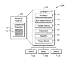
- FIG. 1A shows a block diagram of a muscle compression system according to an embodiment
- FIG. 1B shows a schematic diagram of muscle compression system according to an embodiment
- FIG. 2A shows a partial view of a compression segment according to an embodiment
- FIG. 2B shows multiple layers of a compression segment according to an embodiment
- FIG. 3A shows a compression apparatus of a muscle compression system according to a sleeve configuration
- FIG. 3B shows a muscle compression system attached to a user's limb
- FIG. 3C shows a first side of muscle compression system according to a first wrap configuration
- FIG. 3D shows a first side of a muscle compression system according to a second wrap configuration
- FIG. 3E shows a second side of muscle compression system according to a second wrap configuration
- FIG. 3F shows a top view of the muscle compression system according to the wrap configuration
- FIG. 4 shows a flowchart of a method to compress a muscle of a limb according to an embodiment
- FIG. 5 shows another flowchart of a method to compress a muscle of a limb according to an embodiment
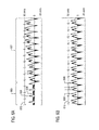
- FIGS. 6A and 6B show results realized by utilizing an embodiment of the system or method disclosed herein;
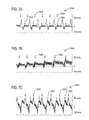
- FIGS. 7A, 7B and 7C show graphs of Doppler ultrasound measurements of the blood flow in the popliteal artery without compression assistance, during unsynchronized compression assistance and during diastolic phase compression assistance, respectively;
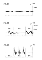
- FIGS. 8A, 8B and 8C show graphs of venous flow at rest, during exercise and based on compression assistance, respectively;
- FIGS. 9A, 9B and 9C show graphs of arterial flow at rest, during exercise and based on compression assistance, respectively;
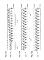
- FIGS. 10A, 10B and 10C show graphs of ultrasound measurements of popliteal arterial blood flow demonstrating the sustained impact of properly timed compression over 2-minute compression period, namely, at a first 10-second interval, a second 10-second interval and a last 10-second interval, respectively;
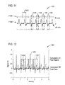
- FIG. 11 shows a graph of an electrocardiogram (ECG) signal correlated to flow of a popliteal artery velocity with timing of compression;
- ECG electrocardiogram
- FIG. 12 shows a graph of timing of compression during diastolic phase and when the muscle is in an inactive state
- FIG. 13 shows a wearer using a pair of compression systems on legs according to an embodiment
- FIG. 14 shows a wearer using a muscle compression system on an arm according to an embodiment.
- Muscles require a continuous supply of oxygenated blood to properly function and ward off fatigue (remove metabolic waste).
- the ability of the body to perform perambulatory motion for an extended period of time is limited by various factors, some of which include genetics, physical fitness level and cardiovascular efficiency.
- a subject has an ability to increase oxygen introduced into the subject's body to a genetic maximum efficiency (VO 2MAX ) through exercise and training. Once VO 2MAX is reached, the subject usually seeks to maintain this peak efficiency for as long as possible while continuing perambulatory motion. In the presence of pathology, perambulatory motion can be made difficult by a reduction in the circulation of blood and reduced delivery of oxygenated blood.
- the continuous circulation of oxygenated blood throughout the body remains important for homeostatic function.
- the increased circulation of oxygenated blood can aid in future periods of perambulatory motion and clinical treatment of a variety of diseases. This includes, but is not limited to, the removal of metabolic waste products from localized tissue regions, amelioration of the symptoms of muscle fatigue, improved muscle performance in subsequent bouts of exercise, and reducing the likelihood of thrombus formation.
- increased circulation can prevent/reduce the likelihood for thrombus formation, aid with wound healing, reduce edema, and reduce the stress on the cardiovascular system.
- the apparatus, system and processes described herein provide assistance to the wearer by reducing the effort the heart must perform to maintain, supplement, or enhance cardiovascular performance to accomplish a task or work at hand.
- the apparatus, system and processes described herein below provide assistance to the wearer by improving the local blood flow to the region to aid in recovery after surgery.
- the apparatus, system and processes described herein may be particularly applicable to soldiers, athletes, and other active individuals who depend on good circulation to maintain cardiovascular performance sufficient to accomplish the task or work at hand. Thus, such individuals may benefit from being able to increase benefits achieved via the activation of the skeletal muscle pump (muscle contraction). During periods when the muscle pump is inactive, individuals benefit from being able to maintain or exceed the circulatory benefits present during periods of perambulatory motion.
- FIG. 1A shows a block diagram of an embodiment of a system 100 A.
- the system 100 A may comprise a compression apparatus 110 that is provided to apply pressure to a limb of a user.
- a limb may be a leg, such as a lower leg (such as, without limitation, beneath a knee of the user). In other embodiments, the limb may be an arm.
- the compression apparatus 110 may be applied above the knee, as well.
- the compression apparatus 110 may be a part of a wearable sleeve, sock or garment 115 , which is configured to be worn, or fit around the limb.
- the compression apparatus 110 may comprise a smart material 112 such as, but not limited to, an electroactive polymer.
- the smart material 112 is represented as a fabric.
- the electroactive polymer may be integrated directly into a wearable garment 115 .
- the smart material 112 may include an artificial muscle wherein an artificial muscle includes materials which may contract in response to a stimulus such as electric current or voltage and expand in response to another stimulus or the removal of the stimulus.
- the terms smart material, electroactive polymer and artificial muscle may be used interchangeably.
- the compression apparatus 110 may be able to constrict, or apply pressure, upon receiving an electrical signal to cause the compression apparatus 110 to either constrict/contract or expand.
- a non-limiting example of an amount of compression may be approximately 20-160 mmHg wherein “approximately” is used to mean plus or minus 10.
- the system 100 A may include a control system 140 having a controller 142 , as disclosed in more detail herein, may be set to a maximum applied pressure within this range.
- timing and degree of compression applied by the compression apparatus 110 may be dictated by signal feedback from at least one of physiological sensors and pressure sensors, respectively.
- the use of smart materials 112 allows for actuation of the compression apparatus 110 to occur fast enough to apply compression within a fraction of one cardiac cycle and repeat compression during each cardiac cycle or a subset of heartbeats, in accordance with the details of compression described herein.
- the application of compression which occurs within one diastolic phase of a cardiac cycle may be referred to as the “compression sequence.”
- the compression sequence will be described in more detail in relation to FIG. 3A .
- the system 100 A may include a plurality of sensors 120 , 130 and 135 .
- Sensor 120 hereinafter being referred to as a first sensor 120 .
- Sensor 130 hereinafter being referred to as a second sensor 130 .
- Sensor 135 hereinafter being referred to as a third sensor 135 .
- the first sensor 120 may be located on the limb.
- a non-limiting example of where the first sensor 120 may be located is in between the limb and the compression apparatus 110 .
- a non-limiting example of the first sensor 120 may be a surface electromyography (“EMG”) sensor.
- EMG surface electromyography
- the first sensor 120 is also sometimes referred to as the muscle activity sensor.
- the first sensor 120 may determine, in real-time, a contraction state, or activity, of a muscle in the limb.
- muscle activity may be determined by monitoring and recording electrical activity associated with muscle contractions.
- the first sensor 120 may be used to monitor electrical activity in a limb muscle, such as the calf muscles, specifically the gastrocnemius and soleus muscles.
- the limb muscle may be in the thigh, the upper arm or the forearm, for example.
- the first sensor 120 may be wired or wireless and integrated into the wearable compression apparatus 110 .
- Direct measurement of the electrical activity of the muscle allows for clear determination of muscle contraction patterns, which may be used to determine a window of time when compression would be most beneficial.
- intramuscular pressure is very high and external compression would not be capable of supplementing the actions of the contracted muscle.
- external compression would be of little benefit while the calf muscle is contracted.
- the inventors have determined that external compression would be most beneficial when the muscle is relaxed, or in a non-contracted state, and intramuscular pressure is low.
- the first sensor 120 may indirectly identify muscle activity, such as via an accelerometer to determine limb motion and time compression based upon the readings from the accelerometer.
- the first sensor 120 may include a plurality of sensors or sensor suite wherein the collective data of the suite determines motion or non-motion of a limb to which compression is to be performed.
- the first sensor 120 may include a force sensor, near infrared spectroscopy (NIRS) sensor, or electromyography (EMG) sensor.
- NIRS near infrared spectroscopy
- EMG electromyography
- the second sensor 130 may be provided to measure, in real-time, the systolic and diastolic time delay, cycle or rhythm, wherein the measurement may be taken at the limb.
- the second sensor is sometimes referred to as the cardiac cycle sensor.
- the second sensor 130 may be a non-invasive peripheral blood flow sensor such as, but not limited to, a pulse photoplethysmograph (“PPG”) or near infrared spectroscopy sensor (NIRS).
- PPG pulse photoplethysmograph
- NIRS near infrared spectroscopy sensor
- Peripheral blood flow patterns of the user may be used to set and modify the compression timing of the compression apparatus 110 and makes the compression apparatus 110 customizable to the anatomy and physiology (such, as, but not limited to, vascular system) of the user.
- this measurement may provide for directly measuring arrival of the arterial pulse wave at the limb, which is delayed relative to the timing of the cardiac contraction given by measurements of heart rate from an electrocardiogram (ECG).
- ECG electrocardiogram
- Such delay may be due to height, physical condition, or heretical features of the user.
- the pulse wave delay relative to the timing of the cardiac contraction varies between individuals and further emphasizes the importance of measuring local blood flow at the limb.
- the diastolic phase is a local diastolic phase in one cardiac cycle according to a limb to which compression is to be applied.
- the third sensor 135 may be provided to measure compression to ensure that an identified amount of pressure is actually being applied.
- the third sensor 135 may sometimes be referred to as the pressure sensor.
- the first sensor 120 and the second sensor 130 may be taking real-time, continuous readings of activity associated with the limb wherein the third sensor 135 may be taking real-time, continuous readings either when compression is being applied or even when compressive phases are not being applied.
- when readings are made may be defined as information associated with each sensor may be collected for other reasons, such as, but not limited to, other medical reasons.
- the controller 142 may be in communication with the first sensor 120 and the second sensor 130 to cause the compression apparatus 110 to apply a pressure (compression) to the limb when both the diastolic phase of the local blood flow in the limb takes place and the muscle is in a non-contracted state.
- the controller 142 may comprise a processor 145 such as, but not limited to, a microprocessor. Other parts of the controller 142 may be, but is not limited to, volatile memory 150 , non-volatile memory 155 , a transceiver 160 , and algorithms 165 , or computer program instructions, disclosed later herein.
- the controller 142 or control system 140 may include a power source 162 . In some embodiments, the power may be derived externally.
- power may be derived externally from a shoe as described in U.S. patent application Ser. No. 13/954,364 entitled “SYSTEM AND METHOD FOR SUPPLEMENTING CIRCULATION IN A BODY” filed Jul. 30, 2013, and assigned to Lockheed Martin Corporation, which is incorporated herein by reference as if set forth in full.
- the power source 162 may include a battery source which may be rechargeable.
- the controller 142 may also determine an amount of pressure to apply with the compression apparatus 110 to the limb. Thus, the controller 142 may cause the compression apparatus 110 to vary an amount of pressure applied to the limb based on a rate of blood flow desired in the limb.
- the third sensor 135 provides feedback to the controller 142 to vary the compression of the compression apparatus 110 until it reaches the right pressure.
- the algorithm 165 utilized in the controller 142 may be used to identify a swing phase of walking by the user, when the calf muscle is not contracted, based on the electrical activity and the muscle activity information will be used to determine the actions of the compression system 100 A.
- the algorithm 165 operated by the control system 140 may be used to identify the local diastolic phase of the local blood flow pattern. Though a single algorithm is disclosed, the functions described may be performed by a plurality of algorithms.
- the processor 145 may include any type of stationary computing device or a mobile computing device.
- the processor 145 may include one or more processors.
- system memory may be volatile (such as RAM), non-volatile (such as read only memory (ROM), flash memory, and the like) or some combination of the two.
- System memory may store an operating system, one or more applications, and may include program data for performing the process of methods 400 and 500 , described in detail below.
- the control system 140 may carry out one or more blocks of methods 400 and 500 .
- the control system 140 may also have additional features or functionality.
- control system 140 may also include additional data storage devices (removable and/or non-removable) such as, for example, magnetic disks, optical disks, or tape.
- Computer storage media may include volatile and non-volatile, non-transitory, removable and non-removable media implemented in any method or technology for storage of data, such as computer readable instructions, data structures, program modules or other data.
- System memory, removable storage and non-removable storage are all examples of computer storage media.
- Computer storage media includes, but is not limited to, RAM, ROM, Electrically Erasable Read-Only Memory (EEPROM), flash memory or other memory technology, compact-disc-read-only memory (CD-ROM), digital versatile disks (DVD) or other optical storage, magnetic cassettes, magnetic tape, magnetic disk storage or other magnetic storage devices, or any other physical medium which can be used to store the desired data and which can be accessed by a processor. Any such computer storage media may be part of the control system 140 .
- the control system 140 may also include or have interfaces for input device(s) (not shown) such as a keyboard, mouse, pen, voice input device, touch input device, etc.
- input device(s) such as a keyboard, mouse, pen, voice input device, touch input device, etc.
- the control system 140 may store collected data from sensors and provide a cardiac analysis report or performance analysis, such as related to any of the graphs described herein.
- the control system 140 may include a peripheral bus for connecting to peripherals.
- the control system 140 may contain communication connection(s) or transceiver 160 that allow the system 140 to communicate with other computing devices, such as over a network or a wireless network.
- communication connection(s) may include wired media such as a wired network or direct-wired connection, and wireless media such as acoustic, radio frequency (RF), infrared and other wireless media.
- the control system 140 may include a network interface card to connect (wired or wireless) to a network.
- Computer program code for carrying out operations described above may be written in a variety of programming languages, including but not limited to a high-level programming language, such as C or C++, for development convenience.
- computer program code for carrying out operations of embodiments described herein may also be written in other programming languages, such as, but not limited to, interpreted languages.
- Some modules or routines may be written in assembly language or even micro-code to enhance performance and/or memory usage. It will be further appreciated that the functionality of any or all of the program modules may also be implemented using discrete hardware components, one or more application specific integrated circuits (ASICs), or a programmed Digital Signal Processor (DSP) or microcontroller.
- ASICs application specific integrated circuits
- DSP Digital Signal Processor
- a code in which a program of the embodiments is described can be included as a firmware in a RAM, a ROM and a flash memory. Otherwise, the code can be stored in a tangible computer-readable storage medium such as a magnetic tape, a flexible disc, a hard disc, a compact disc, a photo-magnetic disc, a digital versatile disc (DVD).
- a tangible computer-readable storage medium such as a magnetic tape, a flexible disc, a hard disc, a compact disc, a photo-magnetic disc, a digital versatile disc (DVD).
- the compression apparatus 110 may include an electromagnet device in lieu of smart material 112 , where the electromagnet device being configured to cause compression in response to an electrical stimulus.
- the compression apparatus 110 may include a pneumatic device or mechanical device to perform the compression. In such configurations, the compression apparatus 110 would receive a source of pneumatic fluid (air or liquid) under the control of control system 140 .
- the system 100 may include a pneumatic fluid source (not shown).
- the controller 142 may vary the voltage or current supplied to the artificial muscle, smart material or electromagnet. In another embodiment, the controller 142 may vary a working or pneumatic fluid channeled to bladders of the compression apparatus 110 .
- Hybrid configurations may be implemented.
- a non-limiting example, a hybrid configuration may include structural instabilities to exploit rapid transition between two states, as with snap-actuators.
- combined electromagnetic/hydraulic systems can be implemented including, but not limited to, magneto-reactive fluids or solenoid pistons.
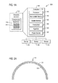
- FIG. 1B shows a schematic diagram of a muscle compression system according to an embodiment.
- Each segment 112 B of the compression apparatus 110 B may comprise connections to a data, power and/or compression timing bus 144 B from the control system 140 B.
- Each segment 112 B of the compression apparatus 110 B connects to the data, power and compression bus 144 B.
- the bus 144 B may include a single line or multiple lines to permit communications between each segment (denoted at 110 B) and the control system 140 B.
- Communications may include sensor data transferred from sensors 120 B and 135 B from the segment to the control system 140 B.
- Communications may include the transfer of a current or voltage such as an electrical stimulus to activate the segment such as the artificial muscle, represented as cross-hatched to denote a fabric, threads or an electroactive polymer.
- the communication protocol used may provide rapid access to each segment on a one-by-one basis by the control system 140 B.
- the bus 144 B may provide power to the plurality of sensors 120 B, 130 B and 135 B.
- Each segment may sometimes be referred to as a compression cuff.
- the segment may completely surround the limb muscle or partially surround the limb muscle.
- the plurality of sensors 120 B, 130 B and 135 B are represented as dashed line circles.
- the sensors 120 B and 135 B may be integrated in an active layer within the segments, as will be described in more detail. While the sensors 120 B and 135 B are represented as dashed lines, in each segment, one or more of the sensors may be omitted. For example, not all segments may require a muscle activity sensor. Therefore, the layers of the segments may vary.
- the sensor 130 B is represented separate from the segments of the compression apparatus 110 B. However, the sensor 130 B in an embodiment is integrated into the garment 115 ( FIG. 1A ) at a location which allows the cardiac cycle to be sensed.
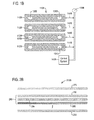
- FIG. 2A shows a partial view of a compression segment of the compression apparatus 110 according to an embodiment.
- the compression apparatus 110 may comprise multiple layers of materials such as, but not limited to, two layers of materials. As illustrated a layer closest to the limb may be or comprise the sensor 135 which is provided to measure an actual pressure being applied. An outer, or second layer, may be or comprise the electroactive polymer, or smart material 112 .
- FIG. 2B shows multiple layers of a compression segment 212 B according to an embodiment.
- Each of segments 212 B may comprise a data, power and/or compression connection to the control system 140 B.
- Each segment 212 B connects to a data, power and compression bus.
- the segment 212 B is a modular segment. As shown in FIG. 2B , the segment 112 ( FIG. 1A ) includes two layers.
- the modular segment 212 B may have a plurality of layers that can be varied based on the application needs.
- the segment 212 B includes a plurality of active layers 280 .
- the active layers include layers 282 , 284 and 286 . There can be more or less layers used as dictated by the application. Additionally, some layers as shown can be implemented as a single “physical” layer or with portals through layers connecting element layers together.
- layer 282 may be a muscle activity sensor layer which may serve as the muscle activity sensor.
- Layer 284 may be a pressure sensor layer which may serve as the pressure sensor.
- Layer 286 may be a compression layer which may include an artificial muscle, for example.
- layers 275 and 290 are shown sandwiching the active layers 280 and may be part of the garment 115 ( FIG. 1A ).
- the layer 275 may be an inside or interior layer wherein the inside or interior layer being in direct contact with the skin of the wearer.
- Layer 290 may be an exterior layer.
- the pressure sensor layer (i.e., layer 284 ) and muscle activity sensor layer (i.e., layer 282 ) might be integrated into a single physical layer or single physical unit.
- the muscle activity sensor layer (i.e., layer 282 ) and the inside or interior layer 275 might be integrated so that elements of the sensor pass through the layer 275 to make skin contact.
- the active layers 280 may be enclosed by layers 275 and 290 which protect the wearer and the active layers such as from sweat from the wearer and moisture in the environment, for example.
- One implementation of the layers 275 and 290 integrate all necessary active layers.
- the compression layer 286 may move separately from any of the other layers wherein the compression layer 286 provides a compressive force to the limb it is wrapped around.
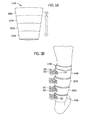
- FIG. 3A shows a compression apparatus 310 A of a muscle compression system according to a sleeve configuration.
- the compression apparatus 310 A may have a plurality of compression segments 305 A, 306 A, 307 A, and 308 A. Instead of each segment 305 A, 306 A, 307 A, and 308 A compressing at the same time, compression takes place according to a compression sequence.
- the compression sequence may begin at the (first) segment 305 A furthest from a heart of the user and conclude at the (last) segment 308 A closest to the heart of the user during the local diastolic phase of the blood flow. Compression on any intermediate segments 306 A and 307 A follows in a similar sequence between the first segment 305 A and the last segment 308 A.
- the apparatus 310 A may have more or less segments.
- the segment constricts to exert a force of pressure on the limb or limb muscle. Compression is released or terminated after the compression sequence, upon detection of the end of the diastolic phase of the cardiac cycle.
- the third sensor 135 may be provided for each segment 305 A, 306 A, 307 A, and 308 A so that pressure may be measured for each compression to ensure that compression reaches a desired pressure for each segment.
- the sleeve configuration generally surrounds the limb and maintains its position on the limb during a non-compression state.
- the sleeve is generally continuous with the circumference varied to accommodate the anatomical profile of a portion of the limb whether the calf, thigh, upper arm or forearm.
- the compression segments may be integrated into a sock. In a sock configuration, the compression segments may be located in the portion which fits around the calf and above the ankle.
- FIG. 3B shows another embodiment of a backside of the compression apparatus 310 B.
- the segments may not form a continuous compression apparatus 310 B as disclosed in FIG. 3A .
- each segment 305 B, 306 B, 307 B and 308 B may be an individual strip with tabs 350 which can be sized to fit a user using hook and loop fastening assemblies 352 and 355 .
- the strip can be tightened around the limb for a snug fit.
- the strip may be layered as described in FIG. 2B .
- FIG. 3A and FIG. 3B show multiple segments where a milking pattern is utilized (as represented by the arrow in between 1 and 4), these embodiments are not meant to be limiting.
- a different compression sequence may be utilized.
- the compression sequence may include activating for compression segments 305 A and 307 A, together or in series; or segments 306 A and 308 A together or in series.
- the compression sequence may repeat at least once or until the diastolic phase is complete in the current cardiac cycle or muscle activity is sensed.
- the compression sequence may be varied based on the expected duration of the diastolic phase wherein the diastolic phase may vary such as the result of the intensity of activity of the wearer.
- the compression sequence may be synchronized to the diastolic phase.
- the compression apparatus 310 A or 310 B may not have multiple compression segments, but may have a single compression segment.
- the single compression segment may exert a force of pressure for a duration of the diastolic phase.
- the single compression segment may exert a force of pressure which is applied and then relaxed repeatedly for the duration of the diastolic phase or until muscle activity is sensed.
- the second sensor 130 may be attached to the limb from or through the apparatus.
- the amount of compression for each segment may vary based on blood flow measured with the second sensor 130 . More specifically, each segment may be compressed based on local arterial blood flow and local muscle activation. Thus, compression per segment may be provided only when the monitored readings identify when compression is most beneficial. Though compression is to be performed during the diastolic phase, compressive subsets may be performed during this phase. As a non-limiting example, a rate of compression may be at a level to provide for two complete compressive cycles (compression sequence) of the segments to occur. In another non-limiting example, only a smaller subset of segments may be utilized.
- Monitoring the amount of pressure applied may be done with the controller 142 employing a real time data processing to monitor physiological parameters such as, but not limited to, heartbeats and mechanical parameters such as, but not limited to, applied pressure, in order to control when and how much pressure is applied to the limb.
- Real time data processing may involve continuous monitoring of the applied pressure and comparison to a pre-set maximum applied pressure. This ensures that the desired operating pressure is achieved for each compression and compression is ceased once this threshold is met.
- an apparatus may be provided for applying external compression to the limb of the user based on real-time readings regarding a cardiac cycle of the user measured at the limb and muscle contractions measured at the limb. Compression is applied when both the local blood flow is in a diastolic phase, as measured on the limb, and the muscle is in a non-contracted state.
- the smart material such as, but not limited to, an electroactive polymer is a part of the apparatus and which provides for the actual compressive effect.
- the artificial muscle is at least partially located around the limb, namely, at a backside and along sides of the limb. When the limb is a leg, the artificial muscle wraps around the gastrocnemius and soleus muscles located on the backside of the leg. More specifically, with respect to the leg, circumferential pressure may be preferred.
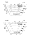
- FIG. 3C shows a first side of muscle compression system 300 C according to a first wrap configuration.
- the garment 315 C may be secured to a limb using hook-and-loop fastening straps 350 with hook and loop fasteners 352 and 355 .
- the hook and loop fasteners 352 and 355 may be substituted with other fasteners, such as without limitation, zippers, adhesives, tapes, external flexible bandages, etc.
- the muscle compression system 300 C includes a plurality of active layers 380 embedded or sandwiched between layers 373 and 390 with layer 390 partially removed to show the underlying layers of the active layer 380 and the layer 375 . Between the segments, gaps 360 are provided. The gap 360 may represent the absence of material.
- the active layers 380 may include sensors 320 or 335 denoted by the dashed circle. The sensor may be integrated into the layers or a separate element. As also described previously, one or more sensors may be omitted for a particular segment.
- the control system 340 communicates with the active layers 380 and/or sensors 320 and 335 .
- the sensor 330 is omitted, but may be included.
- the cardiac cycle sensor 330 may be remote from the garment 315 C so that the cardiac cycle may be sensed elsewhere on the wearer's body. Hence, the remote cardiac cycle sensor would communicate with the control system 340 to provide the cardiac cycle timing so that the compression sequence can be derived.
- the number of segments may vary.
- the length of the segment is shorter than the width of the garment. However, the length of the segment should allow a compression effect on the limb or limb muscle to be realized when worn.
- the segment is represented as an elongated rectangular member.
- the width of the garment corresponds to the dimension which wraps around the circumference of the limb.
- the width of the wrap may also enable the system to be sized for different wearer body types as well as applicability to different limbs (i.e. calf, thigh, forearm, and upper arm).
- FIG. 3D shows a first side of a muscle compression system 300 D according to a second wrap configuration.
- the gaps 360 have been omitted and the cardiac cycle sensor 330 is shown embedded in the garment between the layer 375 and layer 390 .
- the sensor 330 is shown at the top of the garment 315 D.
- FIG. 3E shows a second side of muscle compression system 300 E according to a second wrap configuration with a portion of layer 375 removed exposing a portion of a segment with active layers 380 and layer 390 .
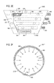
- FIG. 3F shows a top view of the muscle compression system 300 F according to a wrap configuration.
- the compression system 300 F is in a wrapped or installed state around a limb.
- the modular segments take up a part or all of the circumference of the garment wrap 315 F.
- the wrap itself may not completely surround a limb, but rather have the fasteners to complete the loop around the limb.
- the hook-and-loop fastening straps 350 may go completely around the garment 315 F or may be only a small size to close the loop, as shown.
- the modular segments are surrounded by the layers 390 and 375 and the system 300 F is held in place by hook-and-loop fastening straps 350 (or other methods as described previously).
- the external layer 390 is inelastic and does not stretch. When the compression layer in the active layer 380 is activated, the external layer 390 directs the compression inwards towards the limb being compressed, in the direction of the arrows shown.
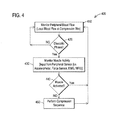
- FIG. 4 shows a flowchart of a method 400 to compress a muscle of a limb according to an embodiment.
- the methods and processes shown herein are for illustrative purposes and represented in a series of blocks. The blocks may be performed sequentially in the order shown or in a different order. One or more of the blocks may be performed contemporaneously. Furthermore, one or more of the blocks may be added or omitted.
- system 100 A is worn during motion of the user such as during work or sports activities.
- system 100 A may be used such as while a user is sleeping. However, while sleeping, the user may get up or may move their legs.
- the compression is not applied during muscle movement, activity or contraction.
- the compression is only applied for the fraction of time in the cardiac cycle that relates to the diastolic phase or period.
- the method 400 comprises monitoring, or measuring, peripheral blood flow, namely, blood flow, at block 410 .
- the blood flow may be measured locally at the limb.
- the blood flow may be measured at the heart.
- a determination is made when the cardiac cycle is either in a diastolic phase or at the end of a systolic phase, at block 420 . If the blood flow is measured locally, the local diastolic phase (or end of a systolic phase) is used to directly synchronize the compression timing.
- a delay is used to synchronize timing of the compression to the local diastolic phase realized at the limb. If the diastolic phase is not detected at block 420 , the method loops back to block 410 .
- the diastolic phase is detected based on the determination at block 420 , monitoring of muscle activity of the limb occurs, at block 430 .
- a determination is made if the muscle is activated, or in a contracted state, at block 440 . If the muscle is not contracted, or in a non-activated (or relaxed) state, compression occurs, at block 450 . If in a contracted state or the muscle is detected as being activated, no compression occurs and the method loops back to block 410 . In other words, the compression timing synchronization to a local diastolic phase is essentially aborted/terminated. However, cardiac cycle monitoring/sensing and muscle activity may be performed essentially continuously. Block 450 loops back to block 410 .
- the compression sequence may be repeated such that multiple compression sequences are used in a single diastolic phase or the compression sequence may be one sequence to terminate at or near the end of the diastolic phase.
- the method may be supplemented with additional blocks related to the sensing/monitoring of the pressure being applied by the compression cuff wherein the compression effect caused by the compression apparatus may be varied based on the pressure sensing readings.
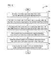
- FIG. 5 shows another flowchart of a method.
- the method 500 provides for monitoring, in real-time, peripheral blood flow at a limb of a user with at least a first sensor attached at the limb, at block 510 .
- the method 500 also comprises determining, in real-time with at least the first sensor, when the heart of the user is in a diastolic phase based on the monitored blood flow at the limb, at block 520 . If the peripheral blood flow is determined to be in a diastolic phase, the method 500 further comprises determining, in real-time, whether a muscle in the limb is in a non-contracted state with at least a second sensor, at block 530 . If the muscle is in the non-contracted state, the method further comprises applying pressure to the muscle with a compression apparatus as initiated by a controller, at block 540 .
- the method may further comprise measuring pressure applied by the compression apparatus to ensure that a correct amount of pressure is applied during compression, at block 550 .
- the method 500 may further comprise analyzing when the muscle is in the non-contracted state to further determine when to apply pressure to the muscle, at block 560 .
- one or more of the blocks may be performed contemporaneously with other blocks. Furthermore, the order may be modified.
- Applying pressure (compression) to the muscle with the compression apparatus may further comprise, during the diastolic phase, applying pressure in a sequence with the compression apparatus having a plurality of sections individually compressible which apply pressure in a sequence where a first section furthest from the heart is contracted, or compressed, first and a last section that is closest to the heart is contracted, or compressed, last.
- each individual compression may be based on information garnered from sensors measuring local arterial blood flow and muscle activation. This information may be used as input to a real time control system, as part of a controller, to quickly react to changes in physiological behavior and determine when compression should be applied. Further, the timing of compression based on local arterial blood flow allows for independent timing for each limb based on current local conditions.
- the timing of compression may be relative to each heartbeat, but can also be customized to a subset of heartbeats such as, but not limited to, compressions every other heartbeat.
- the limb will be actively compressed only after the completion of the systolic phase of the localized blood flow. That is, compression will occur during the diastolic phases of the local blood flow. No external compression would be applied during the systolic portion.
- timing will prevent a potential increase in cardiac afterload, which is the pressure the left ventricle must overcome to eject blood from the heart, and disruption of blood flow into the limb.
- Peripheral blood flow information will be used in conjunction with information garnered from muscle activity sensors as input into the timing control for the compression system. It is noted that diastolic phases of the local blood flow may not necessarily align with the periods of calf or limb muscle relaxation. In turn, it may be advantageous to apply compression only when muscle relaxation occurs simultaneously with the diastolic phase of the local blood flow. This triggering based on this timing cycle would require the monitoring of both the flow cycle and limb muscle activity to determine the initiation of compression. As for the energy usage reason, by applying compression only when it will have the most physiological benefit, energy used by the compression system can be reduced. As a non-limiting example, compression during muscle activity does not have physiological benefit, so energy is conserved by delaying compression until muscle contraction has ended.
- FIGS. 6A and 6B show results realized by utilizing an embodiment of the systems or methods disclosed herein.
- the results are illustrated as ultrasound waves measured at the leg in the popliteal artery.
- a systolic peak denoted by arrow 620
- arrow 630 a systolic peak
- FIG. 6B illustrates the effects of the increased blood flow continues even after 2 minutes of compression, during the diastolic phase.
- Arrows 630 are represented in dashed lines while arrows 620 are solid.
- a top line 610 shows the heart rate measured at the heart, namely, not on the limb.
- the measurements below the top line 610 are taken at the limb.
- the measurements at these different locations indicate a time shift between the contraction of the heart and arrival of the systolic pulse wave locally at the limb, which will be unique person to person. This further illustrates why measuring local blood flow at the limb is preferred.
- FIGS. 7A, 7B and 7C show graphs 700 A, 700 B and 700 C of Doppler ultrasound measurements of the blood flow in the popliteal artery without compression assistance, during unsynchronized compression assistance and during diastolic phase compression assistance, respectively.
- the benefits of compressing during the diastolic portion of the local cardiac cycle as outlined in this patent is demonstrated via the examination of changes in blood delivery to the calf region. While the graphs are directed to the leg/limb and calf region, the muscle compression system may be used on the arm muscles, such as in the upper arm or forearm.
- FIG. 7A a Doppler ultrasound measurement of the blood flow in the popliteal artery is shown, which is the main conduit artery supplying blood flow to the calf region, without the application of compression.
- the solid arrows 720 A indicate the systolic peaks, indicative of blood flow into the lower limb that is driven by the contraction of the heart.
- the dashed arrows 730 A indicate the diastolic phase in which blood flow has slowed into the leg.
- FIG. 7B shows the augmentation of the popliteal artery blood flow with the application of compression to the calf region.
- the compression is applied during every heartbeat, but timed predominately during the systolic phase (outside of the local diastole phases).
- the solid arrows 720 B indicate a reduction in blood flow into the leg with each contraction of the heart. This has two main detrimental effects on the cardiac and lower limb muscle function.
- the first effect is the blunted systolic peak indicates a potential increase in cardiac afterload, which is the pressure the left ventricle must overcome to eject blood from the heart. Over time, this can put stress on the heart as it pumps harder to overcome the resistance to flow imparted by improper compression timing.
- the second effect is that the reduction of blood flow into the lower limb reduces the availability of oxygenated blood to the leg muscles.
- FIG. 7C shows the augmentation of the popliteal artery blood flow due to the application of compression based on the timing algorithm outlined in this patent. Specifically, the compression is applied during the local diastolic phases.
- the solid arrows 720 C indicate the higher systolic peak and the dashed arrow 730 C indicate the significantly increased diastolic flow with our compression technique.
- the oxygenated blood delivered to the calf muscle is increased within a cardiac cycle increasing the efficiency of the heart and reducing heart rate as a result of increased cardiac output with each contraction.
- the increased circulation in the leg helps to remove metabolic waste products that can cause muscle fatigue and soreness.
- FIGS. 8A, 8B and 8C show graphs 800 A, 800 B and 800 C of venous flow at rest, during exercise and based on compression assistance, respectively.
- the timing of compression with physiological signals and feedback regarding muscle activity has been shown to be beneficial.
- the venous blood flow (blood flow back to the heart) velocity profile showed large changes with exercise and with the application of compression.
- the contraction (active) states 805 B, 805 C, 809 B and 809 C of the muscle and the relaxed (inactive) states 807 B and 807 C of the muscle are marked or demarcated by the vertical dashed lines.
- FIGS. 9A, 9B and 9C show graphs of arterial flow 900 A, 900 B and 900 C at rest, during exercise and based on compression assistance, respectively.
- the contraction (active) states 905 B, 905 C, 909 B and 909 C of the muscle and the relaxed (inactive) states 907 B and 907 C of the muscle are marked or demarcated by the vertical dashed lines.
- FIGS. 10A, 10B and 10C show graphs 1000 A, 1000 B and 1000 C of ultrasound measurements of popliteal arterial blood flow demonstrating the sustained impact of properly timed compression over a 2-minute compression period, namely, at a first 10-second interval, a second 10-second interval and a last 10-second interval, respectively.
- a baseline is shown in the ultrasound measurements.
- an increase in the peak velocity is shown.
- FIG. 10B a decrease in peak velocity is shown in 1017 B with a steady state represented at arrow A 10 .
- FIG. 11 shows a graph 1100 of an electrocardiogram (ECG) signal 1105 A correlated to flow of a popliteal artery velocity 1105 B with timing of compression represented as lines 1109 .
- the graph 1100 represents the timing of compression 1109 relative to the ECG signal 1105 A measured at the heart and the local peripheral blood flow 1105 B measured using Doppler ultrasound at the compression site on the leg.
- the compression occurs during the local diastolic phase of the local blood flow avoiding the systolic phases.
- the pulse wave delay period PWD is noted on the graph to represent the difference in local and remote diastolic phase commencements.
- FIG. 12 shows a graph 1200 of timing of compression during diastolic phase and when the muscle is in an inactive state of a wearer.
- the graph will vary based on muscle activity assuming that the diastolic phase essentially repeats itself after the systolic phase according to the same time interval.
- the graph 1200 represents the timing of compression (lines), denoted as numeral 1209 , during light exercise (pressing a foot pedal) represented in a dashed line, denoted at 1207 .
- the graph 1200 indicates the application of compression 1209 only during the period when the pedal is not pressed (muscle is not activated/being used).
- the timing is shown in reference to the ECG signal 1205 A measured at the heart indicating compression occurs late in the cardiac diastolic phase to account for the pulse wave time delay, denoted as PWD in FIG. 11 , to the compression site on the leg/limb.
- the compression cycle would be synchronized according to the local diastolic phase according to the local timing realized in the limb. If the diastolic cycle measurements are taken remote from the limb to be compressed, the PWD pulse wave time delay PWD should be compensated for in order to synchronize the measurements of the cardiac diastolic cycle to the local diastolic cycle.
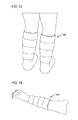
- FIG. 13 shows a wearer using a pair of compression systems 1300 on legs according to an embodiment.
- the wearer may want to use only one system 100 A on one limb such as for recovery after surgery or for other applications.
- the wearer may want to use two systems 100 A of FIG. 1A , represented as system 1300 , or other configurations described herein, on each leg.
- the wearer may use two or more systems 100 A according to their needs on their limbs.
- one or more components of the control system on one limb may be eliminated.
- FIG. 14 shows a wearer using a muscle compression system 1400 on an arm according to an embodiment.
- the system 1400 is installed below the elbow. Nonetheless, the system 1400 may be worn above the elbow on the upper arm.
- step-by-step process for performing the claimed functions herein is a specific algorithm, and may be shown as a mathematical formula, in the text of the specification as prose, and/or in a flow chart.
- the instructions of the software program create a special purpose machine for carrying out the particular algorithm.
- the disclosed structure is a computer, or microprocessor, programmed to carry out an algorithm
- the disclosed structure is not the general purpose computer, but rather the special purpose computer programmed to perform the disclosed algorithm.
- a general purpose computer may be programmed to carry out the algorithm/steps for creating a new machine.
- the general purpose computer becomes a special purpose computer once it is programmed to perform particular functions pursuant to instructions from program software of the embodiments described herein.
- the instructions of the software program that carry out the algorithm/steps electrically change the general purpose computer by creating electrical paths within the device. These electrical paths create a special purpose machine for carrying out the particular algorithm/steps.
Landscapes
- Health & Medical Sciences (AREA)
- Life Sciences & Earth Sciences (AREA)
- Animal Behavior & Ethology (AREA)
- Veterinary Medicine (AREA)
- Public Health (AREA)
- General Health & Medical Sciences (AREA)
- Surgery (AREA)
- Heart & Thoracic Surgery (AREA)
- Medical Informatics (AREA)
- Molecular Biology (AREA)
- Physics & Mathematics (AREA)
- Biomedical Technology (AREA)
- Engineering & Computer Science (AREA)
- Pathology (AREA)
- Biophysics (AREA)
- Cardiology (AREA)
- Physiology (AREA)
- Pain & Pain Management (AREA)
- Physical Education & Sports Medicine (AREA)
- Rehabilitation Therapy (AREA)
- Epidemiology (AREA)
- Hematology (AREA)
- Measuring Pulse, Heart Rate, Blood Pressure Or Blood Flow (AREA)
Abstract
Description
- This application claims benefit of U.S. Provisional Application No. 62/142,931 filed Apr. 3, 2015, incorporated herein by reference as if set forth in full below.
- Embodiments relate to devices, systems and methods of assisting in blood flow to the heart from a limb.
- The vasculature in the body includes veins which have one-way valves to prevent a backflow of blood. In the lower extremities, extra work is required to move blood against gravity to the input side (right atrium) of the heart. The skeletal muscles assist the heart during perambulatory motion by compressing veins in the lower extremities, aiding in emptying the venous circulation and therefore provide assistance in returning blood back to the heart against gravity. The skeletal muscles of the calf or lower extremity muscle groups including, but not limited to, the major muscle groups such as the soleus muscle and gastrocnemius muscle, have been identified as supporting this function. The lower extremity muscle group's actions in facilitating the return of blood back to the heart are referred to as the skeletal muscle pump (human muscle pump) or as the second heart because these muscles provide assistive pumping of venous blood back to the heart from the periphery. The actions, namely, contraction of the muscles and resulting peristaltic blood flow in the lower extremities is generally known as the skeletal muscle pump, or the second heart effect. The skeletal muscle pump is essential for maintaining adequate venous and interstitial fluid flows in the dependent body.
- During periods of inactivity or immobility, the continuous circulation of oxygenated blood throughout the body remains important for homeostatic function. In specific instances of inactivity, the increased circulation of oxygenated blood can aid in future periods of perambulatory motion and/or clinical treatment of a variety of diseases. This includes, but is not limited to, the removal of metabolic waste products from localized tissue regions, amelioration of the symptoms of muscle fatigue, improved muscle performance in subsequent bouts of exercise, and reducing the likelihood of thrombus formation. For clinical treatments, increased circulation can prevent/reduce the likelihood for thrombus formation, aid with wound healing, reduction of edema, and reduce the stress on the cardiovascular system.
- Embodiments related to devices, systems and methods of assisting blood flow to the heart from a limb. In an aspect, a device is provided comprising a wearable garment; and a compression apparatus embedded in the garment for applying an external compression according to a compression sequence to a muscle of a limb of a user based on real-time measurements regarding a cardiac cycle having a diastolic phase and systolic phase of the user and real-time measurements of muscle activity. The compression sequence is synchronized to commence when both the local blood flow at the limb is in the diastolic phase and the muscle is in a non-contracted state.
- An aspect of the embodiments include a system comprising a wearable garment to be worn on a limb of a user; a cardiac cycle sensor to perform real-time measurements regarding a cardiac cycle having a diastolic phase and systolic phase of the user; a muscle activity sensor to perform real-time measurements of muscle contractions in the limb. The system includes a compression apparatus embedded in the garment for applying an external compression to the limb of the user. A processor is coupled to the compression apparatus to control the compression apparatus to apply pressure, according to a compression sequence, to a muscle of the limb based on the real-time measurements of the cardiac cycle of the user and the real-time measurements of the muscle activity. The compression sequence is synchronized to commence when both the local blood flow at the limb is in the diastolic phase and the muscle is in a non-contracted state.
- An aspect of the embodiments includes a method comprising: sensing, by a cardiac cycle sensor, real-time measurements regarding a cardiac cycle having a diastolic phase and systolic phase of a user; sensing, by a muscle activity sensor, real-time measurements of muscle activity in a limb of the user; applying compression, by a compression apparatus, to a muscle in the limb of the user, and controlling the compression, by a processor coupled to the compression apparatus, according to a compression sequence, based on the real-time measurements of the cardiac cycle of the user and the real-time measurements of the muscle contractions wherein the compression sequence is synchronized to commence when both the local blood flow at the limb is in the diastolic phase and the muscle is in a non-contracted state.
- A more particular description briefly stated above will be rendered by reference to specific embodiments thereof that are illustrated in the appended drawings. Understanding that these drawings depict only typical embodiments and are not therefore to be considered to be limiting of its scope, the embodiments will be described and explained with additional specificity and detail through the use of the accompanying drawings in which:
-
FIG. 1A shows a block diagram of a muscle compression system according to an embodiment; -
FIG. 1B shows a schematic diagram of muscle compression system according to an embodiment; -
FIG. 2A shows a partial view of a compression segment according to an embodiment; -
FIG. 2B shows multiple layers of a compression segment according to an embodiment; -
FIG. 3A shows a compression apparatus of a muscle compression system according to a sleeve configuration; -
FIG. 3B shows a muscle compression system attached to a user's limb; -
FIG. 3C shows a first side of muscle compression system according to a first wrap configuration; -
FIG. 3D shows a first side of a muscle compression system according to a second wrap configuration; -
FIG. 3E shows a second side of muscle compression system according to a second wrap configuration; -
FIG. 3F shows a top view of the muscle compression system according to the wrap configuration; -
FIG. 4 shows a flowchart of a method to compress a muscle of a limb according to an embodiment; -
FIG. 5 shows another flowchart of a method to compress a muscle of a limb according to an embodiment; -
FIGS. 6A and 6B show results realized by utilizing an embodiment of the system or method disclosed herein; -
FIGS. 7A, 7B and 7C show graphs of Doppler ultrasound measurements of the blood flow in the popliteal artery without compression assistance, during unsynchronized compression assistance and during diastolic phase compression assistance, respectively; -
FIGS. 8A, 8B and 8C show graphs of venous flow at rest, during exercise and based on compression assistance, respectively; -
FIGS. 9A, 9B and 9C show graphs of arterial flow at rest, during exercise and based on compression assistance, respectively; -
FIGS. 10A, 10B and 10C show graphs of ultrasound measurements of popliteal arterial blood flow demonstrating the sustained impact of properly timed compression over 2-minute compression period, namely, at a first 10-second interval, a second 10-second interval and a last 10-second interval, respectively; -
FIG. 11 shows a graph of an electrocardiogram (ECG) signal correlated to flow of a popliteal artery velocity with timing of compression; -
FIG. 12 shows a graph of timing of compression during diastolic phase and when the muscle is in an inactive state; -
FIG. 13 shows a wearer using a pair of compression systems on legs according to an embodiment; and -
FIG. 14 shows a wearer using a muscle compression system on an arm according to an embodiment. - Embodiments are described herein with reference to the attached figures wherein like reference numerals are used throughout the figures to designate similar or equivalent elements. The figures are not drawn to scale and they are provided merely to illustrate aspects disclosed herein. Several disclosed aspects are described below with reference to non-limiting example applications for illustration. It should be understood that numerous specific details, relationships, and methods are set forth to provide a full understanding of the embodiments disclosed herein. One having ordinary skill in the relevant art, however, will readily recognize that the disclosed embodiments can be practiced without one or more of the specific details or with other methods. In other instances, well-known structures or operations are not shown in detail to avoid obscuring aspects disclosed herein. The embodiments are not limited by the illustrated ordering of acts or events, as some acts may occur in different orders and/or concurrently with other acts or events. Furthermore, not all illustrated acts or events are required to implement a methodology in accordance with the embodiments.
- Notwithstanding that the numerical ranges and parameters setting forth the broad scope are approximations, the numerical values set forth in specific non-limiting examples are reported as precisely as possible. Any numerical value, however, inherently contains certain errors necessarily resulting from the standard deviation found in their respective testing measurements. Moreover, all ranges disclosed herein are to be understood to encompass any and all sub-ranges subsumed therein. For example, a range of “between 0 and 10” can include any and all sub-ranges between (and including) the minimum value of zero and the maximum value of 10, that is, any and all sub-ranges having a minimum value of equal to or greater than zero and a maximum value of equal to or less than 10, e.g., 1 to 4. In some instances, the range may have negative values
- Muscles require a continuous supply of oxygenated blood to properly function and ward off fatigue (remove metabolic waste). The ability of the body to perform perambulatory motion for an extended period of time is limited by various factors, some of which include genetics, physical fitness level and cardiovascular efficiency. A subject has an ability to increase oxygen introduced into the subject's body to a genetic maximum efficiency (VO2MAX) through exercise and training. Once VO2MAX is reached, the subject usually seeks to maintain this peak efficiency for as long as possible while continuing perambulatory motion. In the presence of pathology, perambulatory motion can be made difficult by a reduction in the circulation of blood and reduced delivery of oxygenated blood.
- During periods of inactivity or immobility, the continuous circulation of oxygenated blood throughout the body remains important for homeostatic function. In specific instances of inactivity, the increased circulation of oxygenated blood can aid in future periods of perambulatory motion and clinical treatment of a variety of diseases. This includes, but is not limited to, the removal of metabolic waste products from localized tissue regions, amelioration of the symptoms of muscle fatigue, improved muscle performance in subsequent bouts of exercise, and reducing the likelihood of thrombus formation. For clinical treatments, increased circulation can prevent/reduce the likelihood for thrombus formation, aid with wound healing, reduce edema, and reduce the stress on the cardiovascular system.
- The apparatus, system and processes described herein provide assistance to the wearer by reducing the effort the heart must perform to maintain, supplement, or enhance cardiovascular performance to accomplish a task or work at hand.
- The apparatus, system and processes described herein below provide assistance to the wearer by improving the local blood flow to the region to aid in recovery after surgery.
- The apparatus, system and processes described herein may be particularly applicable to soldiers, athletes, and other active individuals who depend on good circulation to maintain cardiovascular performance sufficient to accomplish the task or work at hand. Thus, such individuals may benefit from being able to increase benefits achieved via the activation of the skeletal muscle pump (muscle contraction). During periods when the muscle pump is inactive, individuals benefit from being able to maintain or exceed the circulatory benefits present during periods of perambulatory motion.
-
FIG. 1A shows a block diagram of an embodiment of asystem 100A. As illustrated, thesystem 100A may comprise acompression apparatus 110 that is provided to apply pressure to a limb of a user. A limb may be a leg, such as a lower leg (such as, without limitation, beneath a knee of the user). In other embodiments, the limb may be an arm. Thecompression apparatus 110 may be applied above the knee, as well. - The
compression apparatus 110 may be a part of a wearable sleeve, sock orgarment 115, which is configured to be worn, or fit around the limb. Thecompression apparatus 110 may comprise asmart material 112 such as, but not limited to, an electroactive polymer. InFIG. 1A , thesmart material 112 is represented as a fabric. Thus, in a non-limiting example, the electroactive polymer may be integrated directly into awearable garment 115. Thesmart material 112 may include an artificial muscle wherein an artificial muscle includes materials which may contract in response to a stimulus such as electric current or voltage and expand in response to another stimulus or the removal of the stimulus. The terms smart material, electroactive polymer and artificial muscle may be used interchangeably. - The
compression apparatus 110 may be able to constrict, or apply pressure, upon receiving an electrical signal to cause thecompression apparatus 110 to either constrict/contract or expand. A non-limiting example of an amount of compression may be approximately 20-160 mmHg wherein “approximately” is used to mean plus or minus 10. - The
system 100A may include acontrol system 140 having acontroller 142, as disclosed in more detail herein, may be set to a maximum applied pressure within this range. - As explained in further detail below, timing and degree of compression applied by the
compression apparatus 110 may be dictated by signal feedback from at least one of physiological sensors and pressure sensors, respectively. The use ofsmart materials 112 allows for actuation of thecompression apparatus 110 to occur fast enough to apply compression within a fraction of one cardiac cycle and repeat compression during each cardiac cycle or a subset of heartbeats, in accordance with the details of compression described herein. The application of compression which occurs within one diastolic phase of a cardiac cycle may be referred to as the “compression sequence.” The compression sequence will be described in more detail in relation toFIG. 3A . - The
system 100A may include a plurality ofsensors Sensor 120 hereinafter being referred to as afirst sensor 120.Sensor 130 hereinafter being referred to as asecond sensor 130.Sensor 135 hereinafter being referred to as athird sensor 135. - The
first sensor 120 may be located on the limb. A non-limiting example of where thefirst sensor 120 may be located is in between the limb and thecompression apparatus 110. A non-limiting example of thefirst sensor 120 may be a surface electromyography (“EMG”) sensor. Thefirst sensor 120 is also sometimes referred to as the muscle activity sensor. - The
first sensor 120 may determine, in real-time, a contraction state, or activity, of a muscle in the limb. With thefirst sensor 120, muscle activity may be determined by monitoring and recording electrical activity associated with muscle contractions. As a non-limiting example, thefirst sensor 120 may be used to monitor electrical activity in a limb muscle, such as the calf muscles, specifically the gastrocnemius and soleus muscles. In an embodiment, the limb muscle may be in the thigh, the upper arm or the forearm, for example. - The
first sensor 120 may be wired or wireless and integrated into thewearable compression apparatus 110. Direct measurement of the electrical activity of the muscle allows for clear determination of muscle contraction patterns, which may be used to determine a window of time when compression would be most beneficial. As a non-limiting example, during muscle contraction, intramuscular pressure is very high and external compression would not be capable of supplementing the actions of the contracted muscle. In turn, external compression would be of little benefit while the calf muscle is contracted. The inventors have determined that external compression would be most beneficial when the muscle is relaxed, or in a non-contracted state, and intramuscular pressure is low. - In addition to analysis of muscle contraction, direct monitoring of muscle electrical signals facilitates the analysis of gait information.
- In an embodiment, the
first sensor 120 may indirectly identify muscle activity, such as via an accelerometer to determine limb motion and time compression based upon the readings from the accelerometer. Thefirst sensor 120 may include a plurality of sensors or sensor suite wherein the collective data of the suite determines motion or non-motion of a limb to which compression is to be performed. Thefirst sensor 120 may include a force sensor, near infrared spectroscopy (NIRS) sensor, or electromyography (EMG) sensor. - The
second sensor 130 may be provided to measure, in real-time, the systolic and diastolic time delay, cycle or rhythm, wherein the measurement may be taken at the limb. The second sensor is sometimes referred to as the cardiac cycle sensor. Thesecond sensor 130 may be a non-invasive peripheral blood flow sensor such as, but not limited to, a pulse photoplethysmograph (“PPG”) or near infrared spectroscopy sensor (NIRS). Thesecond sensor 130 may be remote from the garment as will be described later. Peripheral blood flow patterns of the user may be used to set and modify the compression timing of thecompression apparatus 110 and makes thecompression apparatus 110 customizable to the anatomy and physiology (such, as, but not limited to, vascular system) of the user. More specifically, this measurement may provide for directly measuring arrival of the arterial pulse wave at the limb, which is delayed relative to the timing of the cardiac contraction given by measurements of heart rate from an electrocardiogram (ECG). Such delay may be due to height, physical condition, or heretical features of the user. Thus, the pulse wave delay relative to the timing of the cardiac contraction varies between individuals and further emphasizes the importance of measuring local blood flow at the limb. - In an embodiment, the diastolic phase is a local diastolic phase in one cardiac cycle according to a limb to which compression is to be applied.
- The
third sensor 135 may be provided to measure compression to ensure that an identified amount of pressure is actually being applied. Thethird sensor 135 may sometimes be referred to as the pressure sensor. Thefirst sensor 120 and thesecond sensor 130 may be taking real-time, continuous readings of activity associated with the limb wherein thethird sensor 135 may be taking real-time, continuous readings either when compression is being applied or even when compressive phases are not being applied. With respect to the plurality ofsensors - The
controller 142 may be in communication with thefirst sensor 120 and thesecond sensor 130 to cause thecompression apparatus 110 to apply a pressure (compression) to the limb when both the diastolic phase of the local blood flow in the limb takes place and the muscle is in a non-contracted state. Thecontroller 142 may comprise aprocessor 145 such as, but not limited to, a microprocessor. Other parts of thecontroller 142 may be, but is not limited to,volatile memory 150,non-volatile memory 155, atransceiver 160, andalgorithms 165, or computer program instructions, disclosed later herein. Thecontroller 142 orcontrol system 140 may include apower source 162. In some embodiments, the power may be derived externally. For example, power may be derived externally from a shoe as described in U.S. patent application Ser. No. 13/954,364 entitled “SYSTEM AND METHOD FOR SUPPLEMENTING CIRCULATION IN A BODY” filed Jul. 30, 2013, and assigned to Lockheed Martin Corporation, which is incorporated herein by reference as if set forth in full. In other embodiments, thepower source 162 may include a battery source which may be rechargeable. - The
controller 142 may also determine an amount of pressure to apply with thecompression apparatus 110 to the limb. Thus, thecontroller 142 may cause thecompression apparatus 110 to vary an amount of pressure applied to the limb based on a rate of blood flow desired in the limb. Thethird sensor 135 provides feedback to thecontroller 142 to vary the compression of thecompression apparatus 110 until it reaches the right pressure. - In some embodiments, the
algorithm 165 utilized in thecontroller 142 may be used to identify a swing phase of walking by the user, when the calf muscle is not contracted, based on the electrical activity and the muscle activity information will be used to determine the actions of thecompression system 100A. Thealgorithm 165 operated by thecontrol system 140 may be used to identify the local diastolic phase of the local blood flow pattern. Though a single algorithm is disclosed, the functions described may be performed by a plurality of algorithms. - The
processor 145 may include any type of stationary computing device or a mobile computing device. Theprocessor 145 may include one or more processors. Depending on the exact configuration and type of computing device, system memory may be volatile (such as RAM), non-volatile (such as read only memory (ROM), flash memory, and the like) or some combination of the two. System memory may store an operating system, one or more applications, and may include program data for performing the process ofmethods control system 140 may carry out one or more blocks ofmethods control system 140 may also have additional features or functionality. For example,control system 140 may also include additional data storage devices (removable and/or non-removable) such as, for example, magnetic disks, optical disks, or tape. Computer storage media may include volatile and non-volatile, non-transitory, removable and non-removable media implemented in any method or technology for storage of data, such as computer readable instructions, data structures, program modules or other data. System memory, removable storage and non-removable storage are all examples of computer storage media. Computer storage media includes, but is not limited to, RAM, ROM, Electrically Erasable Read-Only Memory (EEPROM), flash memory or other memory technology, compact-disc-read-only memory (CD-ROM), digital versatile disks (DVD) or other optical storage, magnetic cassettes, magnetic tape, magnetic disk storage or other magnetic storage devices, or any other physical medium which can be used to store the desired data and which can be accessed by a processor. Any such computer storage media may be part of thecontrol system 140. - The
control system 140 may also include or have interfaces for input device(s) (not shown) such as a keyboard, mouse, pen, voice input device, touch input device, etc. In an embodiment, thecontrol system 140 may store collected data from sensors and provide a cardiac analysis report or performance analysis, such as related to any of the graphs described herein. - The
control system 140 may include a peripheral bus for connecting to peripherals. Thecontrol system 140 may contain communication connection(s) ortransceiver 160 that allow thesystem 140 to communicate with other computing devices, such as over a network or a wireless network. By way of example, and not limitation, communication connection(s) may include wired media such as a wired network or direct-wired connection, and wireless media such as acoustic, radio frequency (RF), infrared and other wireless media. Thecontrol system 140 may include a network interface card to connect (wired or wireless) to a network. - Computer program code for carrying out operations described above may be written in a variety of programming languages, including but not limited to a high-level programming language, such as C or C++, for development convenience. In addition, computer program code for carrying out operations of embodiments described herein may also be written in other programming languages, such as, but not limited to, interpreted languages. Some modules or routines may be written in assembly language or even micro-code to enhance performance and/or memory usage. It will be further appreciated that the functionality of any or all of the program modules may also be implemented using discrete hardware components, one or more application specific integrated circuits (ASICs), or a programmed Digital Signal Processor (DSP) or microcontroller. A code in which a program of the embodiments is described can be included as a firmware in a RAM, a ROM and a flash memory. Otherwise, the code can be stored in a tangible computer-readable storage medium such as a magnetic tape, a flexible disc, a hard disc, a compact disc, a photo-magnetic disc, a digital versatile disc (DVD).
- In the embodiment of
FIG. 1A , thecompression apparatus 110 may include an electromagnet device in lieu ofsmart material 112, where the electromagnet device being configured to cause compression in response to an electrical stimulus. In an embodiment, thecompression apparatus 110 may include a pneumatic device or mechanical device to perform the compression. In such configurations, thecompression apparatus 110 would receive a source of pneumatic fluid (air or liquid) under the control ofcontrol system 140. Furthermore, thesystem 100 may include a pneumatic fluid source (not shown). - In an embodiment, the
controller 142 may vary the voltage or current supplied to the artificial muscle, smart material or electromagnet. In another embodiment, thecontroller 142 may vary a working or pneumatic fluid channeled to bladders of thecompression apparatus 110. - Hybrid configurations may be implemented. A non-limiting example, a hybrid configuration may include structural instabilities to exploit rapid transition between two states, as with snap-actuators. Alternatively, combined electromagnetic/hydraulic systems can be implemented including, but not limited to, magneto-reactive fluids or solenoid pistons.
-
FIG. 1B shows a schematic diagram of a muscle compression system according to an embodiment. Each segment 112B of thecompression apparatus 110B may comprise connections to a data, power and/orcompression timing bus 144B from the control system 140B. Each segment 112B of thecompression apparatus 110B connects to the data, power andcompression bus 144B. Thebus 144B may include a single line or multiple lines to permit communications between each segment (denoted at 110B) and the control system 140B. Communications may include sensor data transferred fromsensors bus 144B may provide power to the plurality ofsensors - The plurality of
sensors sensors sensors - The
sensor 130B is represented separate from the segments of thecompression apparatus 110B. However, thesensor 130B in an embodiment is integrated into the garment 115 (FIG. 1A ) at a location which allows the cardiac cycle to be sensed. -
FIG. 2A shows a partial view of a compression segment of thecompression apparatus 110 according to an embodiment. Thecompression apparatus 110 may comprise multiple layers of materials such as, but not limited to, two layers of materials. As illustrated a layer closest to the limb may be or comprise thesensor 135 which is provided to measure an actual pressure being applied. An outer, or second layer, may be or comprise the electroactive polymer, orsmart material 112. -
FIG. 2B shows multiple layers of acompression segment 212B according to an embodiment. Each ofsegments 212B may comprise a data, power and/or compression connection to the control system 140B. Eachsegment 212B connects to a data, power and compression bus. Thesegment 212B is a modular segment. As shown inFIG. 2B , the segment 112 (FIG. 1A ) includes two layers. - The
modular segment 212B may have a plurality of layers that can be varied based on the application needs. Thesegment 212B includes a plurality ofactive layers 280. The active layers includelayers layer 282 may be a muscle activity sensor layer which may serve as the muscle activity sensor.Layer 284 may be a pressure sensor layer which may serve as the pressure sensor.Layer 286 may be a compression layer which may include an artificial muscle, for example. - In the illustration, layers 275 and 290 are shown sandwiching the
active layers 280 and may be part of the garment 115 (FIG. 1A ). Thelayer 275 may be an inside or interior layer wherein the inside or interior layer being in direct contact with the skin of the wearer.Layer 290 may be an exterior layer. - In an embodiment, the pressure sensor layer (i.e., layer 284) and muscle activity sensor layer (i.e., layer 282) might be integrated into a single physical layer or single physical unit. As an additional example, the muscle activity sensor layer (i.e., layer 282) and the inside or
interior layer 275 might be integrated so that elements of the sensor pass through thelayer 275 to make skin contact. Theactive layers 280 may be enclosed bylayers layers compression layer 286 may move separately from any of the other layers wherein thecompression layer 286 provides a compressive force to the limb it is wrapped around. -
FIG. 3A shows acompression apparatus 310A of a muscle compression system according to a sleeve configuration. As shown, thecompression apparatus 310A may have a plurality ofcompression segments segment segment 305A furthest from a heart of the user and conclude at the (last)segment 308A closest to the heart of the user during the local diastolic phase of the blood flow. Compression on anyintermediate segments first segment 305A and thelast segment 308A. While the embodiment illustrates four segments, theapparatus 310A may have more or less segments. During compression, the segment constricts to exert a force of pressure on the limb or limb muscle. Compression is released or terminated after the compression sequence, upon detection of the end of the diastolic phase of the cardiac cycle. - The
third sensor 135 may be provided for eachsegment - The sleeve configuration generally surrounds the limb and maintains its position on the limb during a non-compression state. The sleeve is generally continuous with the circumference varied to accommodate the anatomical profile of a portion of the limb whether the calf, thigh, upper arm or forearm. In an embodiment, the compression segments may be integrated into a sock. In a sock configuration, the compression segments may be located in the portion which fits around the calf and above the ankle.
-
FIG. 3B shows another embodiment of a backside of thecompression apparatus 310B. As illustrated inFIG. 3B , the segments may not form acontinuous compression apparatus 310B as disclosed inFIG. 3A . Instead, eachsegment tabs 350 which can be sized to fit a user using hook andloop fastening assemblies FIG. 2B . - Though both
FIG. 3A andFIG. 3B show multiple segments where a milking pattern is utilized (as represented by the arrow in between 1 and 4), these embodiments are not meant to be limiting. In another non-limiting example, a different compression sequence may be utilized. For example, the compression sequence may include activating forcompression segments segments - In yet another non-limiting example, the
compression apparatus - In the embodiment of
FIG. 3B , the second sensor 130 (FIG. 1A ) may be attached to the limb from or through the apparatus. - In a non-limiting example, the amount of compression for each segment may vary based on blood flow measured with the
second sensor 130. More specifically, each segment may be compressed based on local arterial blood flow and local muscle activation. Thus, compression per segment may be provided only when the monitored readings identify when compression is most beneficial. Though compression is to be performed during the diastolic phase, compressive subsets may be performed during this phase. As a non-limiting example, a rate of compression may be at a level to provide for two complete compressive cycles (compression sequence) of the segments to occur. In another non-limiting example, only a smaller subset of segments may be utilized. - Monitoring the amount of pressure applied may be done with the
controller 142 employing a real time data processing to monitor physiological parameters such as, but not limited to, heartbeats and mechanical parameters such as, but not limited to, applied pressure, in order to control when and how much pressure is applied to the limb. Real time data processing may involve continuous monitoring of the applied pressure and comparison to a pre-set maximum applied pressure. This ensures that the desired operating pressure is achieved for each compression and compression is ceased once this threshold is met. - Thus, as illustrated above, an apparatus may be provided for applying external compression to the limb of the user based on real-time readings regarding a cardiac cycle of the user measured at the limb and muscle contractions measured at the limb. Compression is applied when both the local blood flow is in a diastolic phase, as measured on the limb, and the muscle is in a non-contracted state. The smart material such as, but not limited to, an electroactive polymer is a part of the apparatus and which provides for the actual compressive effect. In an embodiment, the artificial muscle is at least partially located around the limb, namely, at a backside and along sides of the limb. When the limb is a leg, the artificial muscle wraps around the gastrocnemius and soleus muscles located on the backside of the leg. More specifically, with respect to the leg, circumferential pressure may be preferred.
-
FIG. 3C shows a first side ofmuscle compression system 300C according to a first wrap configuration. As a wrap, the garment 315C may be secured to a limb using hook-and-loop fastening straps 350 with hook andloop fasteners loop fasteners - The
muscle compression system 300C includes a plurality ofactive layers 380 embedded or sandwiched betweenlayers 373 and 390 withlayer 390 partially removed to show the underlying layers of theactive layer 380 and thelayer 375. Between the segments,gaps 360 are provided. Thegap 360 may represent the absence of material. Theactive layers 380 may includesensors - The
control system 340 communicates with theactive layers 380 and/orsensors sensor 330 is omitted, but may be included. For example, in some embodiments, thecardiac cycle sensor 330 may be remote from the garment 315C so that the cardiac cycle may be sensed elsewhere on the wearer's body. Hence, the remote cardiac cycle sensor would communicate with thecontrol system 340 to provide the cardiac cycle timing so that the compression sequence can be derived. - The number of segments may vary. The length of the segment is shorter than the width of the garment. However, the length of the segment should allow a compression effect on the limb or limb muscle to be realized when worn. The segment is represented as an elongated rectangular member. The width of the garment corresponds to the dimension which wraps around the circumference of the limb.
- The width of the wrap may also enable the system to be sized for different wearer body types as well as applicability to different limbs (i.e. calf, thigh, forearm, and upper arm).
-
FIG. 3D shows a first side of amuscle compression system 300D according to a second wrap configuration. In this configuration, thegaps 360 have been omitted and thecardiac cycle sensor 330 is shown embedded in the garment between thelayer 375 andlayer 390. Thesensor 330 is shown at the top of the garment 315D. -
FIG. 3E shows a second side ofmuscle compression system 300E according to a second wrap configuration with a portion oflayer 375 removed exposing a portion of a segment withactive layers 380 andlayer 390. -
FIG. 3F shows a top view of themuscle compression system 300F according to a wrap configuration. Thecompression system 300F is in a wrapped or installed state around a limb. The modular segments take up a part or all of the circumference of thegarment wrap 315F. The wrap itself may not completely surround a limb, but rather have the fasteners to complete the loop around the limb. The hook-and-loop fastening straps 350 may go completely around thegarment 315F or may be only a small size to close the loop, as shown. The modular segments are surrounded by thelayers system 300F is held in place by hook-and-loop fastening straps 350 (or other methods as described previously). Theexternal layer 390 is inelastic and does not stretch. When the compression layer in theactive layer 380 is activated, theexternal layer 390 directs the compression inwards towards the limb being compressed, in the direction of the arrows shown. -
FIG. 4 shows a flowchart of amethod 400 to compress a muscle of a limb according to an embodiment. The methods and processes shown herein are for illustrative purposes and represented in a series of blocks. The blocks may be performed sequentially in the order shown or in a different order. One or more of the blocks may be performed contemporaneously. Furthermore, one or more of the blocks may be added or omitted. - In some embodiment, the
system 100A is worn during motion of the user such as during work or sports activities. In some embodiment,system 100A may be used such as while a user is sleeping. However, while sleeping, the user may get up or may move their legs. Thus, as will be apparent from the description herein, the compression is not applied during muscle movement, activity or contraction. In some embodiments, the compression is only applied for the fraction of time in the cardiac cycle that relates to the diastolic phase or period. - As illustrated, the
method 400 comprises monitoring, or measuring, peripheral blood flow, namely, blood flow, atblock 410. In an embodiment, the blood flow may be measured locally at the limb. In an embodiment, the blood flow may be measured at the heart. Based on the monitoring, atblock 410, a determination is made when the cardiac cycle is either in a diastolic phase or at the end of a systolic phase, atblock 420. If the blood flow is measured locally, the local diastolic phase (or end of a systolic phase) is used to directly synchronize the compression timing. If the blood flow is measured at the heart of the wearer/user such as by a remote cardiac cycle sensor, a delay is used to synchronize timing of the compression to the local diastolic phase realized at the limb. If the diastolic phase is not detected atblock 420, the method loops back to block 410. - If the diastolic phase is detected based on the determination at
block 420, monitoring of muscle activity of the limb occurs, atblock 430. A determination is made if the muscle is activated, or in a contracted state, atblock 440. If the muscle is not contracted, or in a non-activated (or relaxed) state, compression occurs, atblock 450. If in a contracted state or the muscle is detected as being activated, no compression occurs and the method loops back to block 410. In other words, the compression timing synchronization to a local diastolic phase is essentially aborted/terminated. However, cardiac cycle monitoring/sensing and muscle activity may be performed essentially continuously. Block 450 loops back to block 410. - In operation, the compression sequence may be repeated such that multiple compression sequences are used in a single diastolic phase or the compression sequence may be one sequence to terminate at or near the end of the diastolic phase.
- The method may be supplemented with additional blocks related to the sensing/monitoring of the pressure being applied by the compression cuff wherein the compression effect caused by the compression apparatus may be varied based on the pressure sensing readings.
-
FIG. 5 shows another flowchart of a method. As illustrated themethod 500 provides for monitoring, in real-time, peripheral blood flow at a limb of a user with at least a first sensor attached at the limb, atblock 510. Themethod 500 also comprises determining, in real-time with at least the first sensor, when the heart of the user is in a diastolic phase based on the monitored blood flow at the limb, atblock 520. If the peripheral blood flow is determined to be in a diastolic phase, themethod 500 further comprises determining, in real-time, whether a muscle in the limb is in a non-contracted state with at least a second sensor, atblock 530. If the muscle is in the non-contracted state, the method further comprises applying pressure to the muscle with a compression apparatus as initiated by a controller, atblock 540. - The method may further comprise measuring pressure applied by the compression apparatus to ensure that a correct amount of pressure is applied during compression, at
block 550. Themethod 500 may further comprise analyzing when the muscle is in the non-contracted state to further determine when to apply pressure to the muscle, atblock 560. As can be appreciated one or more of the blocks may be performed contemporaneously with other blocks. Furthermore, the order may be modified. - Applying pressure (compression) to the muscle with the compression apparatus may further comprise, during the diastolic phase, applying pressure in a sequence with the compression apparatus having a plurality of sections individually compressible which apply pressure in a sequence where a first section furthest from the heart is contracted, or compressed, first and a last section that is closest to the heart is contracted, or compressed, last.
- Thus, in operation, each individual compression may be based on information garnered from sensors measuring local arterial blood flow and muscle activation. This information may be used as input to a real time control system, as part of a controller, to quickly react to changes in physiological behavior and determine when compression should be applied. Further, the timing of compression based on local arterial blood flow allows for independent timing for each limb based on current local conditions. The timing of compression may be relative to each heartbeat, but can also be customized to a subset of heartbeats such as, but not limited to, compressions every other heartbeat. The limb will be actively compressed only after the completion of the systolic phase of the localized blood flow. That is, compression will occur during the diastolic phases of the local blood flow. No external compression would be applied during the systolic portion.
- When actual compression occurs is important based on physiological and energy usage reasons. Regarding the physiology based reasoning, timing will prevent a potential increase in cardiac afterload, which is the pressure the left ventricle must overcome to eject blood from the heart, and disruption of blood flow into the limb. Peripheral blood flow information will be used in conjunction with information garnered from muscle activity sensors as input into the timing control for the compression system. It is noted that diastolic phases of the local blood flow may not necessarily align with the periods of calf or limb muscle relaxation. In turn, it may be advantageous to apply compression only when muscle relaxation occurs simultaneously with the diastolic phase of the local blood flow. This triggering based on this timing cycle would require the monitoring of both the flow cycle and limb muscle activity to determine the initiation of compression. As for the energy usage reason, by applying compression only when it will have the most physiological benefit, energy used by the compression system can be reduced. As a non-limiting example, compression during muscle activity does not have physiological benefit, so energy is conserved by delaying compression until muscle contraction has ended.
-
FIGS. 6A and 6B show results realized by utilizing an embodiment of the systems or methods disclosed herein. The results are illustrated as ultrasound waves measured at the leg in the popliteal artery. As shown inFIG. 6A , when no compression is applied, at 605, a systolic peak, denoted byarrow 620, is higher (more blood is flowing) than at the diastolic peak (less blood is flowing as the heart is relaxed), denoted asarrow 630. When compression is applied, at 607 during the diastolic phase of the cardiac cycle, blood flow is then increased during the diastolic phase.FIG. 6B illustrates the effects of the increased blood flow continues even after 2 minutes of compression, during the diastolic phase.Arrows 630 are represented in dashed lines whilearrows 620 are solid. - As is also illustrated in
FIGS. 6A and 6B , atop line 610 shows the heart rate measured at the heart, namely, not on the limb. The measurements below thetop line 610 are taken at the limb. As explained above, the measurements at these different locations indicate a time shift between the contraction of the heart and arrival of the systolic pulse wave locally at the limb, which will be unique person to person. This further illustrates why measuring local blood flow at the limb is preferred. -
FIGS. 7A, 7B and 7C showgraphs - In
FIG. 7A , a Doppler ultrasound measurement of the blood flow in the popliteal artery is shown, which is the main conduit artery supplying blood flow to the calf region, without the application of compression. Thesolid arrows 720A indicate the systolic peaks, indicative of blood flow into the lower limb that is driven by the contraction of the heart. The dashedarrows 730A indicate the diastolic phase in which blood flow has slowed into the leg. - During this phase, the contraction of the heart has ceased and ventricular refilling is occurring (blood is returning to the heart)
-
FIG. 7B shows the augmentation of the popliteal artery blood flow with the application of compression to the calf region. The compression is applied during every heartbeat, but timed predominately during the systolic phase (outside of the local diastole phases). Thesolid arrows 720B indicate a reduction in blood flow into the leg with each contraction of the heart. This has two main detrimental effects on the cardiac and lower limb muscle function. The first effect is the blunted systolic peak indicates a potential increase in cardiac afterload, which is the pressure the left ventricle must overcome to eject blood from the heart. Over time, this can put stress on the heart as it pumps harder to overcome the resistance to flow imparted by improper compression timing. The second effect is that the reduction of blood flow into the lower limb reduces the availability of oxygenated blood to the leg muscles. - Many devices on the market now apply compression at a time interval irrespective of the physiological signals, such as the cardiac cycle, which can reduce circulation and in some cases increase the likelihood of blood pooling and clotting in the lower limbs.
-
FIG. 7C shows the augmentation of the popliteal artery blood flow due to the application of compression based on the timing algorithm outlined in this patent. Specifically, the compression is applied during the local diastolic phases. Thesolid arrows 720C indicate the higher systolic peak and the dashedarrow 730C indicate the significantly increased diastolic flow with our compression technique. Overall, the oxygenated blood delivered to the calf muscle is increased within a cardiac cycle increasing the efficiency of the heart and reducing heart rate as a result of increased cardiac output with each contraction. The increased circulation in the leg helps to remove metabolic waste products that can cause muscle fatigue and soreness. - The benefits of compression such as during exercise can be evident from the description and graphs below. The exercise conducted included application of pressure on a foot pedal.
-
FIGS. 8A, 8B and 8C showgraphs FIGS. 8B and 8C , the contraction (active) states 805B, 805C, 809B and 809C of the muscle and the relaxed (inactive) states 807B and 807C of the muscle are marked or demarcated by the vertical dashed lines. -
FIGS. 9A, 9B and 9C show graphs ofarterial flow FIGS. 9B and 9C , the contraction (active) states 905B, 905C, 909B and 909C of the muscle and the relaxed (inactive) states 907B and 907C of the muscle are marked or demarcated by the vertical dashed lines. - With the depression of a weighted foot pedal, the muscle pump was activated resulting in increased popliteal venous blood flow (
FIG. 8B ) as would normally happen during walking. During therelaxation phase 807B when the pedal is not pressed, venous flow decreases and blood pools in the leg/limb. In contrast, when active compression was applied, timed to the periods in which the muscle pump is not active and during the diastolic phase of the cardiac cycle, venous flow was increased during the resting phase of exercise with eachcompression 807C (FIG. 8C ). Again, work is reduced for the heart due to more blood returned and expelled for each beat and active compression aids in venous return when the muscle pump is “off.” On the arterial side (FIG. 9C ), circulation is increased during the relaxation phase active state of exercise with the proper timing of compression (the periods in which the muscle pump is not active and during the diastolic phase of the cardiac cycle) 907C. -
FIGS. 10A, 10B and 10C showgraphs - In
FIG. 10B , a decrease in peak velocity is shown in 1017B with a steady state represented at arrow A 10. -
FIG. 11 shows agraph 1100 of an electrocardiogram (ECG)signal 1105A correlated to flow of apopliteal artery velocity 1105B with timing of compression represented aslines 1109. Thegraph 1100 represents the timing ofcompression 1109 relative to theECG signal 1105A measured at the heart and the localperipheral blood flow 1105B measured using Doppler ultrasound at the compression site on the leg. The compression occurs during the local diastolic phase of the local blood flow avoiding the systolic phases. The pulse wave delay period PWD is noted on the graph to represent the difference in local and remote diastolic phase commencements. -
FIG. 12 shows agraph 1200 of timing of compression during diastolic phase and when the muscle is in an inactive state of a wearer. The graph will vary based on muscle activity assuming that the diastolic phase essentially repeats itself after the systolic phase according to the same time interval. Thegraph 1200 represents the timing of compression (lines), denoted as numeral 1209, during light exercise (pressing a foot pedal) represented in a dashed line, denoted at 1207. Thegraph 1200 indicates the application ofcompression 1209 only during the period when the pedal is not pressed (muscle is not activated/being used). The timing is shown in reference to the ECG signal 1205A measured at the heart indicating compression occurs late in the cardiac diastolic phase to account for the pulse wave time delay, denoted as PWD inFIG. 11 , to the compression site on the leg/limb. In an embodiment, the compression cycle would be synchronized according to the local diastolic phase according to the local timing realized in the limb. If the diastolic cycle measurements are taken remote from the limb to be compressed, the PWD pulse wave time delay PWD should be compensated for in order to synchronize the measurements of the cardiac diastolic cycle to the local diastolic cycle. -
FIG. 13 shows a wearer using a pair ofcompression systems 1300 on legs according to an embodiment. In some embodiment, the wearer may want to use only onesystem 100A on one limb such as for recovery after surgery or for other applications. In some embodiments, the wearer may want to use twosystems 100A ofFIG. 1A , represented assystem 1300, or other configurations described herein, on each leg. The wearer may use two ormore systems 100A according to their needs on their limbs. In some pairs ofsystems 100A, one or more components of the control system on one limb may be eliminated. -
FIG. 14 shows a wearer using amuscle compression system 1400 on an arm according to an embodiment. Thesystem 1400 is installed below the elbow. Nonetheless, thesystem 1400 may be worn above the elbow on the upper arm. - From a military, athletic, and physical laborer perspective, increased endurance, reduced fatigue and faster recovery times after physical activity may be realized. Those who sit for extended periods of time, such as, but not limited to, unmanned aerial vehicles (“UAV”) pilots, extreme video garners who sit for extended durations, etc., may benefit from reduced blood pooling in their lower extremities. Air travelers may also benefit from a reduced risk of deep vein thrombosis (“DVT”). Airlines could supply embodiments disclosed herein to all passengers as they board an aircraft. The rhythmic compression helps blood continue circulating in the lower extremities and should reduce the risk of DVT. Embodiments may also be used by individuals in space to reduce loss of muscle mass when remaining in outer space for an extended period of time.
- The “step-by-step process” for performing the claimed functions herein is a specific algorithm, and may be shown as a mathematical formula, in the text of the specification as prose, and/or in a flow chart. The instructions of the software program create a special purpose machine for carrying out the particular algorithm. Thus, in any means-plus-function claim herein in which the disclosed structure is a computer, or microprocessor, programmed to carry out an algorithm, the disclosed structure is not the general purpose computer, but rather the special purpose computer programmed to perform the disclosed algorithm.
- A general purpose computer, or microprocessor, may be programmed to carry out the algorithm/steps for creating a new machine. The general purpose computer becomes a special purpose computer once it is programmed to perform particular functions pursuant to instructions from program software of the embodiments described herein. The instructions of the software program that carry out the algorithm/steps electrically change the general purpose computer by creating electrical paths within the device. These electrical paths create a special purpose machine for carrying out the particular algorithm/steps.
- In particular, unless specifically stated otherwise as apparent from the discussion, it is appreciated that throughout the description, discussions utilizing terms such as “processing” or “computing” or “calculating” or “determining” or “displaying” or the like, refer to the action and processes of a control system, or similar electronic computing device, that manipulates and transforms data represented as physical (electronic) quantities within the computer system's registers and memories into other data similarly represented as physical quantities within the computer system memories or registers or other such data storage, transmission or display devices.
- The terminology used herein is for the purpose of describing particular embodiments only and is not intended to be limiting. As used herein, the singular forms “a,” “an,” and “the” are intended to include the plural forms as well, unless the context clearly indicates otherwise. Furthermore, to the extent that the terms “including,” “includes,” “having,” “has,” “with,” or variants thereof are used in either the detailed description and/or the claims, such terms are intended to be inclusive in a manner similar to the term “comprising.” Moreover, unless specifically stated, any use of the terms first, second, etc., does not denote any order or importance, but rather the terms first, second, etc., are used to distinguish one element from another.
- Unless otherwise defined, all terms (including technical and scientific terms) used herein have the same meaning as commonly understood by one of ordinary skill in the art to which embodiments belongs. It will be further understood that terms, such as those defined in commonly used dictionaries, should be interpreted as having a meaning that is consistent with their meaning in the context of the relevant art and will not be interpreted in an idealized or overly formal sense unless expressly so defined herein.
- While various disclosed embodiments have been described above, it should be understood that they have been presented by way of example only, and not limitation. Numerous changes, omissions and/or additions to the subject matter disclosed herein can be made in accordance with the embodiments disclosed herein without departing from the spirit or scope of the embodiments. Also, equivalents may be substituted for elements thereof without departing from the spirit and scope of the embodiments. In addition, while a particular feature may have been disclosed with respect to only one of several implementations, such feature may be combined with one or more other features of the other implementations as may be desired and advantageous for any given or particular application. Furthermore, many modifications may be made to adapt a particular situation or material to the teachings of the embodiments without departing from the scope thereof.
- Therefore, the breadth and scope of the subject matter provided herein should not be limited by any of the above explicitly described embodiments. Rather, the scope of the embodiments should be defined in accordance with the following claims and their equivalents.
Claims (20)
Priority Applications (1)
| Application Number | Priority Date | Filing Date | Title |
|---|---|---|---|
| US15/564,054 US10791943B2 (en) | 2015-04-03 | 2016-04-04 | System and method for synchronizing external compression of a limb for increased blood |
Applications Claiming Priority (3)
| Application Number | Priority Date | Filing Date | Title |
|---|---|---|---|
| US201562142931P | 2015-04-03 | 2015-04-03 | |
| US15/564,054 US10791943B2 (en) | 2015-04-03 | 2016-04-04 | System and method for synchronizing external compression of a limb for increased blood |
| PCT/US2016/025832 WO2016161414A1 (en) | 2015-04-03 | 2016-04-04 | System and method for synchronizing external compression of a limb for increased blood flow |
Related Parent Applications (1)
| Application Number | Title | Priority Date | Filing Date |
|---|---|---|---|
| PCT/US2016/025832 A-371-Of-International WO2016161414A1 (en) | 2015-04-03 | 2016-04-04 | System and method for synchronizing external compression of a limb for increased blood flow |
Related Child Applications (1)
| Application Number | Title | Priority Date | Filing Date |
|---|---|---|---|
| US16/909,585 Continuation US11877836B2 (en) | 2015-04-03 | 2020-06-23 | System and method for synchronizing external compression of a limb for increased blood flow |
Publications (2)
| Publication Number | Publication Date |
|---|---|
| US20180098707A1 true US20180098707A1 (en) | 2018-04-12 |
| US10791943B2 US10791943B2 (en) | 2020-10-06 |
Family
ID=57005342
Family Applications (2)
| Application Number | Title | Priority Date | Filing Date |
|---|---|---|---|
| US15/564,054 Active 2036-09-29 US10791943B2 (en) | 2015-04-03 | 2016-04-04 | System and method for synchronizing external compression of a limb for increased blood |
| US16/909,585 Active 2038-03-27 US11877836B2 (en) | 2015-04-03 | 2020-06-23 | System and method for synchronizing external compression of a limb for increased blood flow |
Family Applications After (1)
| Application Number | Title | Priority Date | Filing Date |
|---|---|---|---|
| US16/909,585 Active 2038-03-27 US11877836B2 (en) | 2015-04-03 | 2020-06-23 | System and method for synchronizing external compression of a limb for increased blood flow |
Country Status (3)
| Country | Link |
|---|---|
| US (2) | US10791943B2 (en) |
| CA (1) | CA3019907C (en) |
| WO (1) | WO2016161414A1 (en) |
Cited By (12)
| Publication number | Priority date | Publication date | Assignee | Title |
|---|---|---|---|---|
| US20180177424A1 (en) * | 2016-12-27 | 2018-06-28 | Nihon Kohden Corporation | Attachment tape and pulse photometry probe |
| US20190133873A1 (en) * | 2017-11-06 | 2019-05-09 | Tactile Systems Technology, Inc. | Compression garment systems |
| US10702740B2 (en) | 2018-09-14 | 2020-07-07 | Ts Medical Llc | Portable devices for exercising muscles in the ankle, foot, and/or leg, and related methods |
| US20200276077A1 (en) * | 2019-02-28 | 2020-09-03 | Gary Chiu | Compression device |
| CN113712794A (en) * | 2021-08-23 | 2021-11-30 | 河北华蓝医疗器械有限公司 | Medical pressurization pressure monitoring system |
| US20210386615A1 (en) * | 2020-06-10 | 2021-12-16 | Welch Allyn, Inc. | Wearable health management system |
| US11285073B2 (en) * | 2018-10-22 | 2022-03-29 | John Nigel Lasso | Apparatus for applying periodic pressure to the limb of a patient and method of use |
| USD961023S1 (en) | 2020-02-12 | 2022-08-16 | TS Medical, LLC | Excercise device |
| US11638852B2 (en) | 2018-04-06 | 2023-05-02 | TS Medical, LLC | Portable devices for exercising muscles in the ankle, foot, and/or leg, and related methods |
| USD1012207S1 (en) | 2020-08-12 | 2024-01-23 | TS Medical, LLC | Exercise device |
| US11904204B2 (en) | 2018-02-26 | 2024-02-20 | Ts Medical Llc | Devices and methods for exercising an ankle, foot, and/or leg |
| US12343305B2 (en) | 2020-08-12 | 2025-07-01 | Welch Allyn, Inc. | Health management system |
Families Citing this family (3)
| Publication number | Priority date | Publication date | Assignee | Title |
|---|---|---|---|---|
| EP3709882B1 (en) * | 2017-11-15 | 2024-01-10 | The Florida State University Research Foundation, Inc. | Diagnostic and therapeutic splints |
| US12121493B2 (en) * | 2019-08-16 | 2024-10-22 | The Feinstein Institutes For Medical Research | System and method for optimization of CPR chest compressions |
| CN119791021B (en) * | 2025-02-21 | 2025-10-17 | 上海交通大学 | Multi-degree-of-freedom animal centrifuge, automatic anti-gravity adjustment and vital sign detection protection method |
Citations (19)
| Publication number | Priority date | Publication date | Assignee | Title |
|---|---|---|---|---|
| US20050075531A1 (en) * | 2003-10-07 | 2005-04-07 | Loeb Marvin P. | Devices and methods for non-invasively improving blood circulation |
| US20050159690A1 (en) * | 2003-12-29 | 2005-07-21 | Jacob Barak | Method and apparatus for assisting vascular flow through external compression synchronized with venous phasic flow |
| US20100105993A1 (en) * | 2007-05-23 | 2010-04-29 | Ic Therapeutics, Inc. | Methods and apparatus for noninvasive ischemic conditioning |
| US20110066091A1 (en) * | 2004-10-11 | 2011-03-17 | Convatec Technologies Inc. | Electro active compression bandage |
| US20110313482A1 (en) * | 2010-05-28 | 2011-12-22 | Dupelle Michael R | Systems and methods for enhanced venous return flow during cardiac event |
| US8197416B1 (en) * | 2005-08-19 | 2012-06-12 | Ravi Shankar | Pulsatile measurement of cardiac malfunction conditions |
| US20120203132A1 (en) * | 2009-06-19 | 2012-08-09 | Gbveintech Ltd. | Device and method for applying pressure to a body limb |
| US20130102939A1 (en) * | 2010-07-06 | 2013-04-25 | Aleksey Monesovich Sudarev | Method and devices providing impact on cardiovascular system |
| US20130204106A1 (en) * | 2011-07-24 | 2013-08-08 | John A. Bennett | Cloud-Based Monitoring of Medical Devices |
| US20140052028A1 (en) * | 2012-08-18 | 2014-02-20 | Wright Therapy Products, Inc. | Methods for determining the size of body parts as part of compression therapy procedures |
| US20140358193A1 (en) * | 2011-11-11 | 2014-12-04 | Declan Lyons | Apparatus and methods for prevention of syncope |
| US20150290073A1 (en) * | 2007-09-19 | 2015-10-15 | William H. Reeves | Method and system for treating person suffering from a circulatory disorder |
| US20160058644A1 (en) * | 2014-08-26 | 2016-03-03 | Elwha Llc | Garment system including at least one muscle or joint activity sensor and at least one actuator responsive to the sensor and related methods |
| US20160120733A1 (en) * | 2014-10-30 | 2016-05-05 | Elwha Llc | Garment system including at least one sensor and at least one actuator responsive to the sensor and related methods |
| US20160120734A1 (en) * | 2014-10-30 | 2016-05-05 | Elwha Llc | Garment system including at least one sensor and at least one actuator responsive to the sensor and related methods |
| US20160220808A1 (en) * | 2015-01-29 | 2016-08-04 | Elwha Llc | Garment system including at least one sensor and at least one actuator responsive to the sensor and related methods |
| US20160235965A1 (en) * | 2013-10-08 | 2016-08-18 | University Of Prince Edward Island | Ischemic training apparatus and method |
| US20170000360A1 (en) * | 2013-11-28 | 2017-01-05 | University Of Western Sydney | Blood volume monitor |
| US20190083353A1 (en) * | 2015-12-30 | 2019-03-21 | Syncardon Llc | Apparatus and method for promoting wound healing |
Family Cites Families (34)
| Publication number | Priority date | Publication date | Assignee | Title |
|---|---|---|---|---|
| US3866604A (en) | 1973-09-28 | 1975-02-18 | Avco Everett Res Lab Inc | External cardiac assistance |
| US4372297A (en) | 1980-11-28 | 1983-02-08 | The Kendall Company | Compression device |
| ATE111337T1 (en) | 1989-03-16 | 1994-09-15 | Kendall & Co | FULL LENGTH COMPRESSIBLE CUFF. |
| US5263473A (en) | 1990-11-05 | 1993-11-23 | The Kendall Company | Compression device for the limb |
| US6893409B1 (en) | 1991-09-27 | 2005-05-17 | Kci Licensing, Inc. | Foot mounted venous compression device |
| US5514079A (en) | 1992-08-11 | 1996-05-07 | Dillon; Richard S. | Method for promoting circulation of blood |
| US5968073A (en) | 1997-11-17 | 1999-10-19 | Jacobs; Laura F. | Methods and apparatus for applying pressure |
| JP3027750B1 (en) | 1999-05-17 | 2000-04-04 | 日本コーリン株式会社 | Lower limb upper limb blood pressure index measuring device and lower limb blood pressure measuring device |
| US7048702B2 (en) | 2002-06-13 | 2006-05-23 | Vasomedical, Inc. | External counterpulsation and method for minimizing end diastolic pressure |
| US6921373B1 (en) | 2002-11-13 | 2005-07-26 | Myron Z. Bernstein | Method and apparatus for a peripheral circulation enhancement system |
| EP1718261A4 (en) * | 2004-02-04 | 2009-05-20 | Flowmedic Ltd | A method and system for external counterpulsation |
| US7942838B2 (en) | 2004-03-22 | 2011-05-17 | Farrow Medical Innovations, Inc. | Compression garment |
| WO2006014622A2 (en) | 2004-07-19 | 2006-02-09 | Face Bradbury R | Footwear incorporating piezoelectric energy harvesting system |
| US20060058716A1 (en) * | 2004-09-14 | 2006-03-16 | Hui John C K | Unitary external counterpulsation device |
| CN2792415Y (en) * | 2005-04-25 | 2006-07-05 | 中山医科大学生物医学工程开发中心 | Health-care blood vessel rehabilitation equipment |
| US20060247538A1 (en) * | 2005-04-27 | 2006-11-02 | Davis Charles L | Noninvasive method of determining arterial wall tension and arterial segmentation by pulse transit time and pulse wave velocity |
| PT1981459E (en) | 2006-01-13 | 2011-12-21 | Convatec Technologies Inc | Device and system for compression treatment of a body part |
| GB0622415D0 (en) | 2006-11-10 | 2006-12-20 | Huntleigh Technology Plc | Compression system |
| US8175713B1 (en) | 2007-01-10 | 2012-05-08 | Jozef Cywinski | Electro-stimulation device to pump blood from legs |
| US20090036938A1 (en) | 2007-07-30 | 2009-02-05 | Cardiac Pacemakers, Inc. | Method and system for external counterpulsation therapy |
| US8728016B2 (en) * | 2007-09-19 | 2014-05-20 | Quiecor Heart Treatment Centers Of America | Method and system for treating person suffering from a circulatory disorder |
| EP2249922A4 (en) | 2008-02-25 | 2011-12-14 | Autonomic Technologies Inc | Devices, methods, and systems for harvesting energy in the body |
| CA2730238C (en) | 2008-07-08 | 2017-05-09 | Leap Frogg, Llc | Foot compression system |
| KR101019239B1 (en) * | 2008-10-01 | 2011-03-04 | 주식회사이루메디 | Cardiovascular analysis device |
| WO2010111028A1 (en) | 2009-03-24 | 2010-09-30 | Cardiac Pacemakers, Inc. | External cardiac stimulation patch |
| US8597214B2 (en) | 2009-08-14 | 2013-12-03 | Jared Von Holgreen | Apparatus and method for deep vein thrombosis prophylaxis |
| US20110214315A1 (en) | 2010-03-05 | 2011-09-08 | Leap Frogg, Llc | Therapy shoe |
| EP2445320A1 (en) | 2010-10-25 | 2012-04-25 | Max-Planck-Gesellschaft zur Förderung der Wissenschaften e.V. | Energy harvesting cold atmospheric plasma generator |
| US20120065561A1 (en) | 2010-09-03 | 2012-03-15 | Epoch Medical Innovations, Inc. | Device, system, and method for the treatment, prevention and diagnosis of chronic venous insufficiency, deep vein thrombosis, lymphedema and other circulatory conditions |
| US20150257970A1 (en) | 2011-02-17 | 2015-09-17 | Martin Mücke | Device and method for reducing pain |
| WO2012127577A1 (en) | 2011-03-18 | 2012-09-27 | 富士通フロンテック株式会社 | Verification device, verification program, and verification method |
| US8961185B2 (en) * | 2011-08-19 | 2015-02-24 | Pulson, Inc. | System and method for reliably coordinating musculoskeletal and cardiovascular hemodynamics |
| US9168197B2 (en) | 2012-09-28 | 2015-10-27 | Covidien Lp | Vascular compression system |
| US9615992B2 (en) | 2013-07-30 | 2017-04-11 | Lockheed Martin Corporation | System and method for supplementing circulation in a body |
-
2016
- 2016-04-04 US US15/564,054 patent/US10791943B2/en active Active
- 2016-04-04 CA CA3019907A patent/CA3019907C/en active Active
- 2016-04-04 WO PCT/US2016/025832 patent/WO2016161414A1/en not_active Ceased
-
2020
- 2020-06-23 US US16/909,585 patent/US11877836B2/en active Active
Patent Citations (19)
| Publication number | Priority date | Publication date | Assignee | Title |
|---|---|---|---|---|
| US20050075531A1 (en) * | 2003-10-07 | 2005-04-07 | Loeb Marvin P. | Devices and methods for non-invasively improving blood circulation |
| US20050159690A1 (en) * | 2003-12-29 | 2005-07-21 | Jacob Barak | Method and apparatus for assisting vascular flow through external compression synchronized with venous phasic flow |
| US20110066091A1 (en) * | 2004-10-11 | 2011-03-17 | Convatec Technologies Inc. | Electro active compression bandage |
| US8197416B1 (en) * | 2005-08-19 | 2012-06-12 | Ravi Shankar | Pulsatile measurement of cardiac malfunction conditions |
| US20100105993A1 (en) * | 2007-05-23 | 2010-04-29 | Ic Therapeutics, Inc. | Methods and apparatus for noninvasive ischemic conditioning |
| US20150290073A1 (en) * | 2007-09-19 | 2015-10-15 | William H. Reeves | Method and system for treating person suffering from a circulatory disorder |
| US20120203132A1 (en) * | 2009-06-19 | 2012-08-09 | Gbveintech Ltd. | Device and method for applying pressure to a body limb |
| US20110313482A1 (en) * | 2010-05-28 | 2011-12-22 | Dupelle Michael R | Systems and methods for enhanced venous return flow during cardiac event |
| US20130102939A1 (en) * | 2010-07-06 | 2013-04-25 | Aleksey Monesovich Sudarev | Method and devices providing impact on cardiovascular system |
| US20130204106A1 (en) * | 2011-07-24 | 2013-08-08 | John A. Bennett | Cloud-Based Monitoring of Medical Devices |
| US20140358193A1 (en) * | 2011-11-11 | 2014-12-04 | Declan Lyons | Apparatus and methods for prevention of syncope |
| US20140052028A1 (en) * | 2012-08-18 | 2014-02-20 | Wright Therapy Products, Inc. | Methods for determining the size of body parts as part of compression therapy procedures |
| US20160235965A1 (en) * | 2013-10-08 | 2016-08-18 | University Of Prince Edward Island | Ischemic training apparatus and method |
| US20170000360A1 (en) * | 2013-11-28 | 2017-01-05 | University Of Western Sydney | Blood volume monitor |
| US20160058644A1 (en) * | 2014-08-26 | 2016-03-03 | Elwha Llc | Garment system including at least one muscle or joint activity sensor and at least one actuator responsive to the sensor and related methods |
| US20160120733A1 (en) * | 2014-10-30 | 2016-05-05 | Elwha Llc | Garment system including at least one sensor and at least one actuator responsive to the sensor and related methods |
| US20160120734A1 (en) * | 2014-10-30 | 2016-05-05 | Elwha Llc | Garment system including at least one sensor and at least one actuator responsive to the sensor and related methods |
| US20160220808A1 (en) * | 2015-01-29 | 2016-08-04 | Elwha Llc | Garment system including at least one sensor and at least one actuator responsive to the sensor and related methods |
| US20190083353A1 (en) * | 2015-12-30 | 2019-03-21 | Syncardon Llc | Apparatus and method for promoting wound healing |
Cited By (20)
| Publication number | Priority date | Publication date | Assignee | Title |
|---|---|---|---|---|
| US11344238B2 (en) * | 2016-12-27 | 2022-05-31 | Nihon Kohden Corporation | Attachment tape and pulse photometry probe |
| US20180177424A1 (en) * | 2016-12-27 | 2018-06-28 | Nihon Kohden Corporation | Attachment tape and pulse photometry probe |
| US20190133873A1 (en) * | 2017-11-06 | 2019-05-09 | Tactile Systems Technology, Inc. | Compression garment systems |
| US11648172B2 (en) * | 2017-11-06 | 2023-05-16 | Tactile Systems Technology, Inc. | Compression garment systems |
| US12377013B2 (en) | 2017-11-06 | 2025-08-05 | Tactile Systems Technology, Inc. | Compression garment systems |
| US11904204B2 (en) | 2018-02-26 | 2024-02-20 | Ts Medical Llc | Devices and methods for exercising an ankle, foot, and/or leg |
| US11638852B2 (en) | 2018-04-06 | 2023-05-02 | TS Medical, LLC | Portable devices for exercising muscles in the ankle, foot, and/or leg, and related methods |
| US11351417B2 (en) | 2018-09-14 | 2022-06-07 | TS Medical, LLC | Portable devices for exercising muscles in the ankle, foot, and/or leg, and related methods |
| US11207559B2 (en) | 2018-09-14 | 2021-12-28 | Ts Medical Llc | Portable devices for exercising muscles in the ankle, foot, and/or leg, and related methods |
| US11590391B2 (en) | 2018-09-14 | 2023-02-28 | Ts Medical Llc | Portable devices for exercising muscles in the ankle, foot, and/or leg, and related methods |
| US10702740B2 (en) | 2018-09-14 | 2020-07-07 | Ts Medical Llc | Portable devices for exercising muscles in the ankle, foot, and/or leg, and related methods |
| US11285073B2 (en) * | 2018-10-22 | 2022-03-29 | John Nigel Lasso | Apparatus for applying periodic pressure to the limb of a patient and method of use |
| US11559460B2 (en) * | 2019-02-28 | 2023-01-24 | Gary Chiu | Compression device |
| US20200276077A1 (en) * | 2019-02-28 | 2020-09-03 | Gary Chiu | Compression device |
| USD961023S1 (en) | 2020-02-12 | 2022-08-16 | TS Medical, LLC | Excercise device |
| US20210386615A1 (en) * | 2020-06-10 | 2021-12-16 | Welch Allyn, Inc. | Wearable health management system |
| US11918539B2 (en) * | 2020-06-10 | 2024-03-05 | Welch Allyn, Inc. | Wearable health management system |
| USD1012207S1 (en) | 2020-08-12 | 2024-01-23 | TS Medical, LLC | Exercise device |
| US12343305B2 (en) | 2020-08-12 | 2025-07-01 | Welch Allyn, Inc. | Health management system |
| CN113712794A (en) * | 2021-08-23 | 2021-11-30 | 河北华蓝医疗器械有限公司 | Medical pressurization pressure monitoring system |
Also Published As
| Publication number | Publication date |
|---|---|
| US11877836B2 (en) | 2024-01-23 |
| US20210145296A1 (en) | 2021-05-20 |
| CA3019907A1 (en) | 2016-10-06 |
| CA3019907C (en) | 2023-01-17 |
| WO2016161414A1 (en) | 2016-10-06 |
| US10791943B2 (en) | 2020-10-06 |
Similar Documents
| Publication | Publication Date | Title |
|---|---|---|
| US11877836B2 (en) | System and method for synchronizing external compression of a limb for increased blood flow | |
| EP3426136B1 (en) | Apparatus for promoting wound healing | |
| US11583471B2 (en) | CPR chest compression system with tonometric input and feedback | |
| US12599535B2 (en) | External counterpulsation system | |
| CN103282009B (en) | Non-Invasive Devices for CPR | |
| EP2074981B1 (en) | Therapeutic device for increasing muscle strength | |
| US20090036938A1 (en) | Method and system for external counterpulsation therapy | |
| EP2906110B1 (en) | Determination of ventricular pressure and related values | |
| JP2023029597A (en) | Apparatus and methods of sensing patient condition, such as anatomy position, and apparatus and methods of controlling patient applications | |
| JP2014507983A (en) | Apparatus and method for changing the arterial pulsation waveform of a body | |
| JP7325538B2 (en) | CPR DEVICE, CONTROL METHOD AND COMPUTER PROGRAM | |
| CN111374877A (en) | Foot venous thrombosis prevention and treatment device and control method thereof | |
| JP7232351B2 (en) | CPR DEVICE, CONTROL METHOD AND COMPUTER PROGRAM | |
| US20240148265A1 (en) | System and methods for synchronizing externalcompression of a limb for surgical use | |
| Haritha et al. | Varicose vein diagnosis system and therapy: A review | |
| CN113795233A (en) | Cardiopulmonary resuscitation device, control method, and computer program | |
| EP3960136A1 (en) | Apparatus for pulse cycle pressure modulation and variable pressure therapy | |
| Lao | Wearable tactile pressure sensing for compression garments and control of active compression devices | |
| US20080242916A1 (en) | Eecp Device and an Image System Comprising the Same | |
| Chau et al. | Wearable Pulsatile Compression Devices During Intradialytic Promote Individual Quality of Life in Chronic Kidney Disease Patients | |
| CN121694990A (en) | Automated rehabilitation aids and related equipment after breast cancer surgery | |
| Huang et al. | Peripheral hemodynamic effects of synchronizing intermittent compression with cardiac pulsation | |
| Rahimi | Towards the Development of an Adaptive Compression System | |
| Alikhani et al. | Development, design and implementation of a heart rehabilitation system based on External Counter Pulsation (ECP) | |
| Kostka et al. | THE MAGNABOOT FOOT RESCUE: ANew APPROACH TO COMPRESSION THERAPY |
Legal Events
| Date | Code | Title | Description |
|---|---|---|---|
| FEPP | Fee payment procedure |
Free format text: ENTITY STATUS SET TO UNDISCOUNTED (ORIGINAL EVENT CODE: BIG.); ENTITY STATUS OF PATENT OWNER: SMALL ENTITY |
|
| STPP | Information on status: patent application and granting procedure in general |
Free format text: DOCKETED NEW CASE - READY FOR EXAMINATION |
|
| STPP | Information on status: patent application and granting procedure in general |
Free format text: NON FINAL ACTION MAILED |
|
| AS | Assignment |
Owner name: PRESSION INC., CANADA Free format text: ASSIGNMENT OF ASSIGNORS INTEREST;ASSIGNORS:HUGHSON, RICHARD L;PETERSON, SEAN D;PRINCE, CHEKEMA N;AND OTHERS;REEL/FRAME:051215/0654 Effective date: 20160404 |
|
| AS | Assignment |
Owner name: PRESSION LLC, CANADA Free format text: ASSIGNMENT OF ASSIGNORS INTEREST;ASSIGNOR:PRESSION INC.;REEL/FRAME:051225/0683 Effective date: 20190109 |
|
| STPP | Information on status: patent application and granting procedure in general |
Free format text: RESPONSE TO NON-FINAL OFFICE ACTION ENTERED AND FORWARDED TO EXAMINER |
|
| STPP | Information on status: patent application and granting procedure in general |
Free format text: FINAL REJECTION MAILED |
|
| AS | Assignment |
Owner name: PRESSION INC., CANADA Free format text: ASSIGNMENT OF ASSIGNORS INTEREST;ASSIGNOR:LOCKHEED MARTIN CORPORATION;REEL/FRAME:052654/0074 Effective date: 20180822 |
|
| STPP | Information on status: patent application and granting procedure in general |
Free format text: NOTICE OF ALLOWANCE MAILED -- APPLICATION RECEIVED IN OFFICE OF PUBLICATIONS |
|
| FEPP | Fee payment procedure |
Free format text: ENTITY STATUS SET TO SMALL (ORIGINAL EVENT CODE: SMAL); ENTITY STATUS OF PATENT OWNER: SMALL ENTITY |
|
| STPP | Information on status: patent application and granting procedure in general |
Free format text: PUBLICATIONS -- ISSUE FEE PAYMENT RECEIVED |
|
| STPP | Information on status: patent application and granting procedure in general |
Free format text: PUBLICATIONS -- ISSUE FEE PAYMENT VERIFIED |
|
| STCF | Information on status: patent grant |
Free format text: PATENTED CASE |
|
| MAFP | Maintenance fee payment |
Free format text: PAYMENT OF MAINTENANCE FEE, 4TH YR, SMALL ENTITY (ORIGINAL EVENT CODE: M2551); ENTITY STATUS OF PATENT OWNER: SMALL ENTITY Year of fee payment: 4 |