US20180098691A1 - Three-dimensional contour scanning device - Google Patents
Three-dimensional contour scanning device Download PDFInfo
- Publication number
- US20180098691A1 US20180098691A1 US15/726,490 US201715726490A US2018098691A1 US 20180098691 A1 US20180098691 A1 US 20180098691A1 US 201715726490 A US201715726490 A US 201715726490A US 2018098691 A1 US2018098691 A1 US 2018098691A1
- Authority
- US
- United States
- Prior art keywords
- optical path
- sub
- projection
- reflective element
- scanning device
- Prior art date
- Legal status (The legal status is an assumption and is not a legal conclusion. Google has not performed a legal analysis and makes no representation as to the accuracy of the status listed.)
- Granted
Links
Images


Classifications
-
- A—HUMAN NECESSITIES
- A61—MEDICAL OR VETERINARY SCIENCE; HYGIENE
- A61B—DIAGNOSIS; SURGERY; IDENTIFICATION
- A61B5/00—Measuring for diagnostic purposes; Identification of persons
- A61B5/0059—Measuring for diagnostic purposes; Identification of persons using light, e.g. diagnosis by transillumination, diascopy, fluorescence
- A61B5/0082—Measuring for diagnostic purposes; Identification of persons using light, e.g. diagnosis by transillumination, diascopy, fluorescence adapted for particular medical purposes
- A61B5/0088—Measuring for diagnostic purposes; Identification of persons using light, e.g. diagnosis by transillumination, diascopy, fluorescence adapted for particular medical purposes for oral or dental tissue
-
- A—HUMAN NECESSITIES
- A61—MEDICAL OR VETERINARY SCIENCE; HYGIENE
- A61B—DIAGNOSIS; SURGERY; IDENTIFICATION
- A61B1/00—Instruments for performing medical examinations of the interior of cavities or tubes of the body by visual or photographical inspection, e.g. endoscopes; Illuminating arrangements therefor
- A61B1/24—Instruments for performing medical examinations of the interior of cavities or tubes of the body by visual or photographical inspection, e.g. endoscopes; Illuminating arrangements therefor for the mouth, i.e. stomatoscopes, e.g. with tongue depressors; Instruments for opening or keeping open the mouth
-
- A—HUMAN NECESSITIES
- A61—MEDICAL OR VETERINARY SCIENCE; HYGIENE
- A61B—DIAGNOSIS; SURGERY; IDENTIFICATION
- A61B5/00—Measuring for diagnostic purposes; Identification of persons
- A61B5/0059—Measuring for diagnostic purposes; Identification of persons using light, e.g. diagnosis by transillumination, diascopy, fluorescence
- A61B5/0062—Arrangements for scanning
-
- A—HUMAN NECESSITIES
- A61—MEDICAL OR VETERINARY SCIENCE; HYGIENE
- A61B—DIAGNOSIS; SURGERY; IDENTIFICATION
- A61B5/00—Measuring for diagnostic purposes; Identification of persons
- A61B5/103—Measuring devices for testing the shape, pattern, colour, size or movement of the body or parts thereof, for diagnostic purposes
- A61B5/107—Measuring physical dimensions, e.g. size of the entire body or parts thereof
- A61B5/1077—Measuring of profiles
-
- A—HUMAN NECESSITIES
- A61—MEDICAL OR VETERINARY SCIENCE; HYGIENE
- A61B—DIAGNOSIS; SURGERY; IDENTIFICATION
- A61B5/00—Measuring for diagnostic purposes; Identification of persons
- A61B5/103—Measuring devices for testing the shape, pattern, colour, size or movement of the body or parts thereof, for diagnostic purposes
- A61B5/107—Measuring physical dimensions, e.g. size of the entire body or parts thereof
- A61B5/1079—Measuring physical dimensions, e.g. size of the entire body or parts thereof using optical or photographic means
-
- A—HUMAN NECESSITIES
- A61—MEDICAL OR VETERINARY SCIENCE; HYGIENE
- A61B—DIAGNOSIS; SURGERY; IDENTIFICATION
- A61B5/00—Measuring for diagnostic purposes; Identification of persons
- A61B5/45—For evaluating or diagnosing the musculoskeletal system or teeth
- A61B5/4538—Evaluating a particular part of the muscoloskeletal system or a particular medical condition
- A61B5/4542—Evaluating the mouth, e.g. the jaw
- A61B5/4547—Evaluating teeth
-
- A—HUMAN NECESSITIES
- A61—MEDICAL OR VETERINARY SCIENCE; HYGIENE
- A61C—DENTISTRY; APPARATUS OR METHODS FOR ORAL OR DENTAL HYGIENE
- A61C19/00—Dental auxiliary appliances
- A61C19/04—Measuring instruments specially adapted for dentistry
-
- A—HUMAN NECESSITIES
- A61—MEDICAL OR VETERINARY SCIENCE; HYGIENE
- A61C—DENTISTRY; APPARATUS OR METHODS FOR ORAL OR DENTAL HYGIENE
- A61C9/00—Impression cups, i.e. impression trays; Impression methods
- A61C9/004—Means or methods for taking digitized impressions
- A61C9/0046—Data acquisition means or methods
- A61C9/0053—Optical means or methods, e.g. scanning the teeth by a laser or light beam
-
- G—PHYSICS
- G02—OPTICS
- G02B—OPTICAL ELEMENTS, SYSTEMS OR APPARATUS
- G02B26/00—Optical devices or arrangements for the control of light using movable or deformable optical elements
- G02B26/08—Optical devices or arrangements for the control of light using movable or deformable optical elements for controlling the direction of light
- G02B26/10—Scanning systems
-
- G—PHYSICS
- G02—OPTICS
- G02B—OPTICAL ELEMENTS, SYSTEMS OR APPARATUS
- G02B27/00—Optical systems or apparatus not provided for by any of the groups G02B1/00 - G02B26/00, G02B30/00
- G02B27/28—Optical systems or apparatus not provided for by any of the groups G02B1/00 - G02B26/00, G02B30/00 for polarising
- G02B27/288—Filters employing polarising elements, e.g. Lyot or Solc filters
Definitions
- the invention relates in general to a contour scanning device, and more particularly to a three-dimensional contour scanning device.
- Conventional oral cavity scanner emits a projection light to the teeth inside the oral cavity, then the imaging light is reflected from the teeth is analyzed to obtain a surface contour of the teeth.
- some of the projection lights not completely reflected from the teeth are refracted to the inside of the teeth and then are emitted off the teeth.
- the refraction light will affect the accuracy of the surface contour of the teeth.
- the invention is directed to a three-dimensional contour scanning device capable of resolving the abovementioned problems.
- a three-dimensional contour scanning device including an image sensing element, a light source and a single polarity element.
- the light source is used for emitting a projection light to a to-be-scanned object through a projection optical path.
- the projection light reflected from the to-be-scanned object becomes an imaging light further reflected to the image sensing element through an image-formed optical path.
- the single polarity element is disposed on the projection optical path and the image-formed optical path.
- a three-dimensional contour scanning device includes a host, an image sensing element, a light source, a protrusion tube, a reflective element and the single polarizing element.
- the image sensing element is disposed inside the host.
- the light source is disposed inside the host.
- the protrusion tube is detachably connected to the host and has a first opening and a third opening opposite to the first opening, wherein the third opening is adjacent to the host.
- the reflective element is disposed inside the protrusion tube, wherein the first opening is adjacent to the reflective element.
- the single polarity element is disposed inside the protrusion tube.
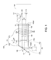
- FIG. 1 is a schematic diagram of a three-dimensional contour scanning device according to an embodiment of the invention.
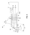
- FIG. 2 is a schematic diagram of a three-dimensional contour scanning device according to another embodiment of the invention.
- FIG. 3 is a schematic diagram of a three-dimensional contour scanning device according to another embodiment of the invention.
- FIG. 4 is a schematic diagram of a three-dimensional contour scanning device according to another embodiment of the invention.
- FIG. 1 is a schematic diagram of a three-dimensional contour scanning device 100 according to an embodiment of the invention.
- the three-dimensional contour scanning device 100 such as an oral cavity scanner, can scan the contour of the teeth inside the oral cavity.
- the three-dimensional contour scanning device 100 of the invention embodiment is not limited to an oral cavity scanner.
- the three-dimensional contour scanning device 100 includes a light source 110 , an image sensing element 115 , an image generation element 120 , a polarity element 125 , a barrel 130 , a projection imaging module 135 , a capturing optical module 140 , a reflective element 145 , a protrusion tube 150 and a host 155 .
- the light source 110 which can be realized by a light emitting diode or a laser light source, is used for emitting a projection light L 1 (illustrated in bold lines) to a to-be-scanned object 10 through a projection optical path P 1 , wherein the to-be-scanned object 10 can be realized by teeth or other to-be-scanned object having a three-dimensional contour.
- the projection light L 1 reflected from the to-be-scanned object 10 becomes an imaging light L 2 (illustrated in bold lines) reflected to the image sensing element 115 through an image-formed optical path P 2 .
- the image sensing element 115 can be realized by a complementary metal-oxide-semiconductor (CMOS).
- CMOS complementary metal-oxide-semiconductor
- the image generation element 120 is located on the projection optical path P 1 and is used for changing a projection pattern of the projection light L 1 .
- the projection pattern is deformed after the projection light L 1 is reflected from the to-be-scanned object 10 .
- the image sensing element 115 or an analyzer (not illustrated) electrically connected to the image sensing element 115 can analyze the deformed projection pattern to obtain a three-dimensional contour of the to-be-scanned object 10 .
- the image generation element 120 can be realized by a digital micro-mirror device (DMD) or a display such as a liquid crystal display (LCD).
- DMD digital micro-mirror device
- LCD liquid crystal display
- the single polarity element 125 is disposed on the projection optical path P 1 and the image-formed optical path P 2 , and the projection light L 1 passing through the polarity element 125 will become a first linearly polarized light.
- the first linearly polarized light having been reflected from the to-be-scanned object, will pass through the same polarity element 125 and become a second linearly polarized light. Since the projection light L 1 and the imaging light L 2 pass through the same polarity element 125 , the first linearly polarized light and the second linearly polarized light have the same polarizing direction.
- the three-dimensional contour scanning device 100 of the invention embodiment uses only one single polarity element 125 , therefore the cost can be reduced and the complexity of optical path can be simplified.
- the polarity element 125 can be realized by a polarizer.
- the imaging light L 2 passes through the polarity element 125 , the surface contour of the to-be-scanned object 10 can be obtained with larger accuracy.
- the imaging light L 2 refracted from the interior of the to-be-scanned object 10 (the polarizing direction changes) will be fully or partly filtered off by the polarity element 125 , and only the imaging light L 2 reflected from the surface of the to-be-scanned object 10 (the polarizing direction does not change) can pass through the polarity element 125 .
- the imaging light L 2 is still refracted from the interior of the to-be-scanned object 10
- the imaging light L 2 refracted from the interior of the to-be-scanned object 10 is filtered off, therefore the surface contour of the to-be-scanned object 10 still can be obtained with larger accuracy.
- the light source 110 , the image sensing element 115 and the image generation element 120 all can be disposed inside the host 155 .
- the barrel 130 is disposed inside the protrusion tube 150 .
- the barrel 130 is fixedly connected to the host 155 and has a second opening 130 a .
- the polarity element 125 can be disposed in the second opening 130 a of the barrel 130 , such that the polarity element 125 is fixedly to the host 155 through the barrel 130 .
- the invention is not limited thereto.
- the projection imaging module 135 may include at least one lens for successfully emitting the projection light L 1 to the reflective element 145 .
- the capturing optical module 140 may include at least one lens for successfully emitting the imaging light L 2 to the image sensing element 115 .
- the projection imaging module 135 and the capturing optical module 140 can be disposed on the barrel 130 or inside the host 155 .
- the reflective element 145 is disposed inside the terminal end 151 of the protrusion tube 150 and forms an angle of 45° with the axis X 1 of the protrusion tube 150 .
- the reflective element 145 is also located on the projection optical path P 1 and the image-formed optical path P 2 for reflecting the projection light L 1 to a to-be-scanned object 10 , and the imaging light L 2 reflected from the to-be-scanned object 10 is further reflected to the image sensing element 115 .
- the protrusion tube 150 has a first opening 150 a 1 located at a terminal end 151 of the protrusion tube 150 .
- the projection light L 1 and the imaging light L 2 pass through the protrusion tube 150 via the first opening 150 a 1 .
- the projection optical path P 1 includes a first sub-projection optical path P 11 and a second sub-projection optical path P 12 .
- the image-formed optical path P 2 includes a first sub-imaging optical path P 21 and a second sub-imaging optical path P 22 .
- the projection light L 1 is emitted to the reflective element 145 through the first sub-projection optical path P 11 and is further reflected to a to-be-scanned object 10 from the reflective element 145 through the second sub-projection optical path P 12 .
- the projection light L 1 reflected from the to-be-scanned object 10 becomes an imaging light L 2 .
- the imaging light L 2 is reflected to the reflective element 145 from the to-be-scanned object 10 through the first sub-imaging optical path P 21 and is further reflected to the image sensing element 115 from the reflective element 145 through the second sub-imaging optical path P 22 .
- the single polarity element 125 is located on the first sub-projection optical path P 11 and the second sub-imaging optical path P 22 such that the projection light L 1 and the imaging light L 2 can pass through the polarity element 125 .
- the protrusion tube 150 has a third opening 150 a 3 .
- the reflective element 145 is projected to the third opening 150 a 3 along the first projection area.
- the single polarity element 125 is located within the first projection area.
- the first projection area refers to the range of projection path through which the reflective element 145 is projected to the third opening 150 a 3 .
- the angle A 1 included between the reflective element 145 and the polarity element 125 is 45°.
- the angle A 1 included between the reflective element 145 and the polarity element 125 is not subjected to specific restrictions, and any angle will do as long as the polarity element 125 is located within the first projection area.
- the angle A 2 included between the first sub-projection optical path P 11 and the second sub-imaging optical path P 22 is smaller than 15°, thus the outer diameter of the protrusion tube 150 can be reduced.
- the larger the angle A 2 the larger the outer diameter D 1 of the protrusion tube 150 is required.
- the smaller the angle A 21 the smaller the outer diameter D 1 of the protrusion tube 150 is required. Since the angle A 2 is smaller than 15°, the protrusion tube 150 can enter the oral with a suitable outer diameter D 1 .
- the cross-section of the protrusion tube 150 has a circular shape, and the outer diameter D 1 of the protrusion tube 150 ranges 0 ⁇ 45 mm.
- the cross-section of the protrusion tube 150 is not circular but has a rectangular shape whose edges and diagonal ranges 0 ⁇ 45 mm.
- the protrusion tube 150 is detachably connected to the host 155 .
- the polarity element 125 and the reflective element 145 can be disposed inside the protrusion tube 150 , and can be detached from or connected to the host 155 along with the protrusion tube 150 , such that the protrusion tube 150 becomes an a disposable element. Since the protrusion tube 150 is a disposable element, when different patients' to-be-scanned objects 10 (such as teeth) need to be scanned, the protrusion tube 150 can be replaced to meet different medical requirements, such as the sizes of the patients' oral cavity, and the patients' gender and/or conditions.
- FIG. 2 is a schematic diagram of a three-dimensional contour scanning device 200 according to another embodiment of the invention.
- the three-dimensional contour scanning device 200 includes a light source 110 , an image sensing element 115 , an image generation element 120 , a polarity element 125 , a projection imaging module 135 , a capturing optical module 140 , a reflective element 145 , a barrel 130 , a protrusion tube 150 and a host 155 .
- the single polarity element 125 of the three-dimensional contour scanning device 200 of the present embodiment is located on the second sub-projection optical path P 12 and the first sub-imaging optical path P 21 . Since the single polarity element 125 is located on the second sub-projection optical path P 12 and the first sub-imaging optical path P 21 , the projection light L 1 and the imaging light L 2 pass through the same polarity element 125 , the three-dimensional contour of the to-be-scanned object 10 can be obtained with larger accuracy. In comparison to the three-dimensional contour scanning device using multiple polarizing elements, the three-dimensional contour scanning device 200 of the invention uses only one single polarity element 125 , therefore the cost can be reduced and the complexity of optical path can be simplified.
- the protrusion tube 150 has a first opening 150 a 1 located at the terminal end 151 of the protrusion tube 150 .
- the projection light L 1 is emitted to the to-be-scanned object 10 through the first opening 150 a 1 .
- the polarity element 125 is disposed inside the first opening 150 a 1 or covers the first opening 150 a 1 , such that the projection light L 1 is also emitted to the to-be-scanned object 10 through the polarity element 125 .
- the reflective element 145 is projected to the first opening 150 a 1 along the second projection area.
- the single polarity element 125 is located within the second projection area.
- the second projection area refers to the range of projection path through which the reflective element 145 is projected to the first opening 150 a 1 .
- the angle A 3 included between the reflective element 145 and the polarity element 125 is 45° is not subjected to specific restrictions, and any angle will do as long as the polarity element 125 is located within the second projection area.
- FIG. 3 is a schematic diagram of a three-dimensional contour scanning device 300 according to another embodiment of the invention.
- the three-dimensional contour scanning device 300 includes a light source 110 , an image sensing element 115 , an image generation element 120 , a polarity element 125 , a barrel 130 , a projection imaging module 135 , a capturing optical module 140 , a reflective element 145 , a protrusion tube 150 and a host 155 .
- the single polarity element 125 of the three-dimensional contour scanning device 100 of the present embodiment is located on the first sub-projection optical path P 11 , the second sub-projection optical path P 12 , the first sub-imaging optical path P 21 and the second sub-imaging optical path P 22 . Since the single polarity element 125 is located on the first sub-projection optical path P 11 , the second sub-projection optical path P 12 , the first sub-imaging optical path P 21 and the second sub-imaging optical path P 22 , the projection light L 1 and the imaging light L 2 can pass through the same polarity element 125 , and the three-dimensional contour of the to-be-scanned object 10 can be obtained with larger accuracy. In comparison to the three-dimensional contour scanning device using multiple polarizing elements, the three-dimensional contour scanning device 300 of the invention uses only one single polarity element 125 , therefore the cost can be reduced and the complexity of optical path can be simplified.
- the reflective element 145 and the polarity element 125 are disposed inside the protrusion tube 150 , and the reflective element 145 and the polarity element 125 are substantially disposed in parallel and adjacent to each other.
- the reflective element 145 and the polarity element 125 can be attached together or can be adjacent to each other but not attached together. However, the invention does not restrict the disposition of the reflective element 145 and the polarity element 125 .
- the reflective element 145 and the polarity element 125 can be attached together or adjacent to each other but not attached together, and any disposition of the reflective element 145 and the polarity element 125 will do as long as the polarity element 125 is located within the first projection area and the second projection area.
- FIG. 4 is a schematic diagram of a three-dimensional contour scanning device 400 according to another embodiment of the invention.
- the three-dimensional contour scanning device 400 includes a light source 110 , an image sensing element 115 , an image generation element 120 , a polarity element 125 , a barrel 130 , a projection imaging module 135 , a capturing optical module 140 , a reflective element 145 , a protrusion tube 150 and a host 155 .
- the three-dimensional contour scanning device 400 of the present embodiment and the three-dimensional contour scanning device 100 have similar features but are different in that that the polarity element 125 of the three-dimensional contour scanning device 400 of the present embodiment is located between the opening 130 a of the barrel 130 and the reflective element 145 and is disposed on the inner wall of the protrusion tube 150 rather than inside the opening 130 a of the barrel 130 .
- the design of having the single polarity element of the three-dimensional contour scanning device of the invention located on the optical path of the projection light and the optical path of the imaging light reduces the cost and/or simplify the complexity of optical path complexity. Since the imaging light passes through the polarizing element, the surface contour of the to-be-scanned object can be obtained with larger accuracy.
- the single polarity element can be disposed inside the protrusion tube, wherein the protrusion tube is detachably connected to the host, such that the polarity element can be detached from the host along with the protrusion tube.
- the single polarity element can also be disposed inside the host directly or through another element such as a barrel.
Landscapes
- Health & Medical Sciences (AREA)
- Life Sciences & Earth Sciences (AREA)
- Physics & Mathematics (AREA)
- Animal Behavior & Ethology (AREA)
- Veterinary Medicine (AREA)
- Public Health (AREA)
- General Health & Medical Sciences (AREA)
- Oral & Maxillofacial Surgery (AREA)
- Dentistry (AREA)
- Surgery (AREA)
- Biophysics (AREA)
- Engineering & Computer Science (AREA)
- Biomedical Technology (AREA)
- Pathology (AREA)
- Medical Informatics (AREA)
- Heart & Thoracic Surgery (AREA)
- Molecular Biology (AREA)
- Optics & Photonics (AREA)
- General Physics & Mathematics (AREA)
- Nuclear Medicine, Radiotherapy & Molecular Imaging (AREA)
- Epidemiology (AREA)
- Radiology & Medical Imaging (AREA)
- Physical Education & Sports Medicine (AREA)
- Rheumatology (AREA)
- Orthopedic Medicine & Surgery (AREA)
- Audiology, Speech & Language Pathology (AREA)
- Facsimile Scanning Arrangements (AREA)
Abstract
Description
- This application claims the benefit of People's Republic of China application Serial No. 201610886262.1, filed Oct. 11, 2016, the subject matter of which is incorporated herein by reference.
- The invention relates in general to a contour scanning device, and more particularly to a three-dimensional contour scanning device.
- Conventional oral cavity scanner emits a projection light to the teeth inside the oral cavity, then the imaging light is reflected from the teeth is analyzed to obtain a surface contour of the teeth. However, some of the projection lights not completely reflected from the teeth are refracted to the inside of the teeth and then are emitted off the teeth. The refraction light will affect the accuracy of the surface contour of the teeth.
- Therefore, it has become a prominent task for those who are versed in the technology field of the invention to resolve the negative influence caused by the refraction light.
- The invention is directed to a three-dimensional contour scanning device capable of resolving the abovementioned problems.
- According to one embodiment of the present invention, a three-dimensional contour scanning device including an image sensing element, a light source and a single polarity element is provided. The light source is used for emitting a projection light to a to-be-scanned object through a projection optical path. The projection light reflected from the to-be-scanned object becomes an imaging light further reflected to the image sensing element through an image-formed optical path. The single polarity element is disposed on the projection optical path and the image-formed optical path.
- According to another embodiment of the present invention, a three-dimensional contour scanning device is provided. The three-dimensional contour scanning device includes a host, an image sensing element, a light source, a protrusion tube, a reflective element and the single polarizing element. The image sensing element is disposed inside the host. The light source is disposed inside the host. The protrusion tube is detachably connected to the host and has a first opening and a third opening opposite to the first opening, wherein the third opening is adjacent to the host. The reflective element is disposed inside the protrusion tube, wherein the first opening is adjacent to the reflective element. The single polarity element is disposed inside the protrusion tube.
- The above and other aspects of the invention will become better understood with regard to the following detailed description of the preferred but non-limiting embodiment (s). The following description is made with reference to the accompanying drawings.
-
FIG. 1 is a schematic diagram of a three-dimensional contour scanning device according to an embodiment of the invention. -
FIG. 2 is a schematic diagram of a three-dimensional contour scanning device according to another embodiment of the invention. -
FIG. 3 is a schematic diagram of a three-dimensional contour scanning device according to another embodiment of the invention. -
FIG. 4 is a schematic diagram of a three-dimensional contour scanning device according to another embodiment of the invention. -
FIG. 1 is a schematic diagram of a three-dimensionalcontour scanning device 100 according to an embodiment of the invention. The three-dimensionalcontour scanning device 100, such as an oral cavity scanner, can scan the contour of the teeth inside the oral cavity. However, the three-dimensionalcontour scanning device 100 of the invention embodiment is not limited to an oral cavity scanner. - The three-dimensional
contour scanning device 100 includes alight source 110, animage sensing element 115, animage generation element 120, apolarity element 125, abarrel 130, aprojection imaging module 135, a capturingoptical module 140, areflective element 145, aprotrusion tube 150 and ahost 155. - The
light source 110, which can be realized by a light emitting diode or a laser light source, is used for emitting a projection light L1 (illustrated in bold lines) to a to-be-scannedobject 10 through a projection optical path P1, wherein the to-be-scannedobject 10 can be realized by teeth or other to-be-scanned object having a three-dimensional contour. The projection light L1 reflected from the to-be-scanned object 10 becomes an imaging light L2 (illustrated in bold lines) reflected to theimage sensing element 115 through an image-formed optical path P2. In an embodiment, theimage sensing element 115 can be realized by a complementary metal-oxide-semiconductor (CMOS). - The
image generation element 120 is located on the projection optical path P1 and is used for changing a projection pattern of the projection light L1. The projection pattern is deformed after the projection light L1 is reflected from the to-be-scanned object 10. Theimage sensing element 115 or an analyzer (not illustrated) electrically connected to theimage sensing element 115 can analyze the deformed projection pattern to obtain a three-dimensional contour of the to-be-scanned object 10. In an embodiment, theimage generation element 120 can be realized by a digital micro-mirror device (DMD) or a display such as a liquid crystal display (LCD). - In the present embodiment, the
single polarity element 125 is disposed on the projection optical path P1 and the image-formed optical path P2, and the projection light L1 passing through thepolarity element 125 will become a first linearly polarized light. The first linearly polarized light, having been reflected from the to-be-scanned object, will pass through thesame polarity element 125 and become a second linearly polarized light. Since the projection light L1 and the imaging light L2 pass through thesame polarity element 125, the first linearly polarized light and the second linearly polarized light have the same polarizing direction. In comparison to the three-dimensional contour scanning device using multiple polarizing elements, the three-dimensionalcontour scanning device 100 of the invention embodiment uses only onesingle polarity element 125, therefore the cost can be reduced and the complexity of optical path can be simplified. In an embodiment, thepolarity element 125 can be realized by a polarizer. - Since the imaging light L2 passes through the
polarity element 125, the surface contour of the to-be-scannedobject 10 can be obtained with larger accuracy. The imaging light L2 refracted from the interior of the to-be-scanned object 10 (the polarizing direction changes) will be fully or partly filtered off by thepolarity element 125, and only the imaging light L2 reflected from the surface of the to-be-scanned object 10 (the polarizing direction does not change) can pass through thepolarity element 125. In the invention, although the imaging light L2 is still refracted from the interior of the to-be-scannedobject 10, the imaging light L2 refracted from the interior of the to-be-scannedobject 10 is filtered off, therefore the surface contour of the to-be-scannedobject 10 still can be obtained with larger accuracy. - Moreover, the
light source 110, theimage sensing element 115 and theimage generation element 120 all can be disposed inside thehost 155. - The
barrel 130 is disposed inside theprotrusion tube 150. Thebarrel 130 is fixedly connected to thehost 155 and has asecond opening 130 a. In the present embodiment, thepolarity element 125 can be disposed in thesecond opening 130 a of thebarrel 130, such that thepolarity element 125 is fixedly to thehost 155 through thebarrel 130. However, the invention is not limited thereto. - The
projection imaging module 135 may include at least one lens for successfully emitting the projection light L1 to thereflective element 145. Similarly, the capturingoptical module 140 may include at least one lens for successfully emitting the imaging light L2 to theimage sensing element 115. Besides, theprojection imaging module 135 and the capturingoptical module 140 can be disposed on thebarrel 130 or inside thehost 155. - As indicated in
FIG. 1 , thereflective element 145 is disposed inside theterminal end 151 of theprotrusion tube 150 and forms an angle of 45° with the axis X1 of theprotrusion tube 150. Thereflective element 145 is also located on the projection optical path P1 and the image-formed optical path P2 for reflecting the projection light L1 to a to-be-scanned object 10, and the imaging light L2 reflected from the to-be-scanned object 10 is further reflected to theimage sensing element 115. Theprotrusion tube 150 has a first opening 150 a 1 located at aterminal end 151 of theprotrusion tube 150. The projection light L1 and the imaging light L2 pass through theprotrusion tube 150 via the first opening 150 a 1. - As indicated in
FIG. 1 , the projection optical path P1 includes a first sub-projection optical path P11 and a second sub-projection optical path P12. The image-formed optical path P2 includes a first sub-imaging optical path P21 and a second sub-imaging optical path P22. The projection light L1 is emitted to thereflective element 145 through the first sub-projection optical path P11 and is further reflected to a to-be-scanned object 10 from thereflective element 145 through the second sub-projection optical path P12. The projection light L1 reflected from the to-be-scanned object 10 becomes an imaging light L2. The imaging light L2 is reflected to thereflective element 145 from the to-be-scanned object 10 through the first sub-imaging optical path P21 and is further reflected to theimage sensing element 115 from thereflective element 145 through the second sub-imaging optical path P22. In the present embodiment, thesingle polarity element 125 is located on the first sub-projection optical path P11 and the second sub-imaging optical path P22 such that the projection light L1 and the imaging light L2 can pass through thepolarity element 125. - As indicated in
FIG. 1 , theprotrusion tube 150 has a third opening 150 a 3. Thereflective element 145 is projected to the third opening 150 a 3 along the first projection area. In the present embodiment, thesingle polarity element 125 is located within the first projection area. The first projection area refers to the range of projection path through which thereflective element 145 is projected to the third opening 150 a 3. Besides, the angle A1 included between thereflective element 145 and thepolarity element 125 is 45°. The angle A1 included between thereflective element 145 and thepolarity element 125 is not subjected to specific restrictions, and any angle will do as long as thepolarity element 125 is located within the first projection area. - As indicated in
FIG. 1 , the angle A2 included between the first sub-projection optical path P11 and the second sub-imaging optical path P22 is smaller than 15°, thus the outer diameter of theprotrusion tube 150 can be reduced. The larger the angle A2, the larger the outer diameter D1 of theprotrusion tube 150 is required. Conversely, the smaller the angle A21, the smaller the outer diameter D1 of theprotrusion tube 150 is required. Since the angle A2 is smaller than 15°, theprotrusion tube 150 can enter the oral with a suitable outer diameter D1. For example, the cross-section of theprotrusion tube 150 has a circular shape, and the outer diameter D1 of theprotrusion tube 150 ranges 0≤45 mm. Or, the cross-section of theprotrusion tube 150 is not circular but has a rectangular shape whose edges and diagonal ranges 0≤45 mm. - The
protrusion tube 150 is detachably connected to thehost 155. Thepolarity element 125 and thereflective element 145 can be disposed inside theprotrusion tube 150, and can be detached from or connected to thehost 155 along with theprotrusion tube 150, such that theprotrusion tube 150 becomes an a disposable element. Since theprotrusion tube 150 is a disposable element, when different patients' to-be-scanned objects 10 (such as teeth) need to be scanned, theprotrusion tube 150 can be replaced to meet different medical requirements, such as the sizes of the patients' oral cavity, and the patients' gender and/or conditions. -
FIG. 2 is a schematic diagram of a three-dimensionalcontour scanning device 200 according to another embodiment of the invention. - The three-dimensional
contour scanning device 200 includes alight source 110, animage sensing element 115, animage generation element 120, apolarity element 125, aprojection imaging module 135, a capturingoptical module 140, areflective element 145, abarrel 130, aprotrusion tube 150 and ahost 155. - Unlike the three-dimensional
contour scanning device 100 of previous embodiments, thesingle polarity element 125 of the three-dimensionalcontour scanning device 200 of the present embodiment is located on the second sub-projection optical path P12 and the first sub-imaging optical path P21. Since thesingle polarity element 125 is located on the second sub-projection optical path P12 and the first sub-imaging optical path P21, the projection light L1 and the imaging light L2 pass through thesame polarity element 125, the three-dimensional contour of the to-be-scanned object 10 can be obtained with larger accuracy. In comparison to the three-dimensional contour scanning device using multiple polarizing elements, the three-dimensionalcontour scanning device 200 of the invention uses only onesingle polarity element 125, therefore the cost can be reduced and the complexity of optical path can be simplified. - In greater details, the
protrusion tube 150 has a first opening 150 a 1 located at theterminal end 151 of theprotrusion tube 150. The projection light L1 is emitted to the to-be-scanned object 10 through the first opening 150 a 1. Thepolarity element 125 is disposed inside the first opening 150 a 1 or covers the first opening 150 a 1, such that the projection light L1 is also emitted to the to-be-scanned object 10 through thepolarity element 125. As indicated inFIG. 2 , thereflective element 145 is projected to the first opening 150 a 1 along the second projection area. In the present embodiment, thesingle polarity element 125 is located within the second projection area. The second projection area refers to the range of projection path through which thereflective element 145 is projected to the first opening 150 a 1. The angle A3 included between thereflective element 145 and thepolarity element 125 is 45° is not subjected to specific restrictions, and any angle will do as long as thepolarity element 125 is located within the second projection area. -
FIG. 3 is a schematic diagram of a three-dimensionalcontour scanning device 300 according to another embodiment of the invention. - The three-dimensional
contour scanning device 300 includes alight source 110, animage sensing element 115, animage generation element 120, apolarity element 125, abarrel 130, aprojection imaging module 135, a capturingoptical module 140, areflective element 145, aprotrusion tube 150 and ahost 155. - Unlike the three-dimensional
contour scanning device 100 of previous embodiment, thesingle polarity element 125 of the three-dimensionalcontour scanning device 100 of the present embodiment is located on the first sub-projection optical path P11, the second sub-projection optical path P12, the first sub-imaging optical path P21 and the second sub-imaging optical path P22. Since thesingle polarity element 125 is located on the first sub-projection optical path P11, the second sub-projection optical path P12, the first sub-imaging optical path P21 and the second sub-imaging optical path P22, the projection light L1 and the imaging light L2 can pass through thesame polarity element 125, and the three-dimensional contour of the to-be-scanned object 10 can be obtained with larger accuracy. In comparison to the three-dimensional contour scanning device using multiple polarizing elements, the three-dimensionalcontour scanning device 300 of the invention uses only onesingle polarity element 125, therefore the cost can be reduced and the complexity of optical path can be simplified. - The
reflective element 145 and thepolarity element 125 are disposed inside theprotrusion tube 150, and thereflective element 145 and thepolarity element 125 are substantially disposed in parallel and adjacent to each other. Thereflective element 145 and thepolarity element 125 can be attached together or can be adjacent to each other but not attached together. However, the invention does not restrict the disposition of thereflective element 145 and thepolarity element 125. Thereflective element 145 and thepolarity element 125 can be attached together or adjacent to each other but not attached together, and any disposition of thereflective element 145 and thepolarity element 125 will do as long as thepolarity element 125 is located within the first projection area and the second projection area. -
FIG. 4 is a schematic diagram of a three-dimensionalcontour scanning device 400 according to another embodiment of the invention. The three-dimensionalcontour scanning device 400 includes alight source 110, animage sensing element 115, animage generation element 120, apolarity element 125, abarrel 130, aprojection imaging module 135, a capturingoptical module 140, areflective element 145, aprotrusion tube 150 and ahost 155. The three-dimensionalcontour scanning device 400 of the present embodiment and the three-dimensionalcontour scanning device 100 have similar features but are different in that that thepolarity element 125 of the three-dimensionalcontour scanning device 400 of the present embodiment is located between the opening 130 a of thebarrel 130 and thereflective element 145 and is disposed on the inner wall of theprotrusion tube 150 rather than inside the opening 130 a of thebarrel 130. - To summarize, the design of having the single polarity element of the three-dimensional contour scanning device of the invention located on the optical path of the projection light and the optical path of the imaging light reduces the cost and/or simplify the complexity of optical path complexity. Since the imaging light passes through the polarizing element, the surface contour of the to-be-scanned object can be obtained with larger accuracy. In an embodiment, the single polarity element can be disposed inside the protrusion tube, wherein the protrusion tube is detachably connected to the host, such that the polarity element can be detached from the host along with the protrusion tube. In another embodiment, the single polarity element can also be disposed inside the host directly or through another element such as a barrel.
- While the invention has been described by way of example and in terms of the preferred embodiment (s), it is to be understood that the invention is not limited thereto. On the contrary, it is intended to cover various modifications and similar arrangements and procedures, and the scope of the appended claims therefore should be accorded the broadest interpretation so as to encompass all such modifications and similar arrangements and procedures.
Claims (19)
Applications Claiming Priority (3)
| Application Number | Priority Date | Filing Date | Title |
|---|---|---|---|
| CN201610886262 | 2016-10-11 | ||
| CN201610886262.1A CN106491082B (en) | 2016-10-11 | 2016-10-11 | Three-dimensional profile scanner |
| CN201610886262.1 | 2016-10-11 |
Publications (2)
| Publication Number | Publication Date |
|---|---|
| US20180098691A1 true US20180098691A1 (en) | 2018-04-12 |
| US10542880B2 US10542880B2 (en) | 2020-01-28 |
Family
ID=58294735
Family Applications (1)
| Application Number | Title | Priority Date | Filing Date |
|---|---|---|---|
| US15/726,490 Active 2037-11-22 US10542880B2 (en) | 2016-10-11 | 2017-10-06 | Three-dimensional contour scanning device |
Country Status (2)
| Country | Link |
|---|---|
| US (1) | US10542880B2 (en) |
| CN (1) | CN106491082B (en) |
Cited By (5)
| Publication number | Priority date | Publication date | Assignee | Title |
|---|---|---|---|---|
| CN109211142A (en) * | 2018-09-19 | 2019-01-15 | 苏州佳世达光电有限公司 | 3 D scanning system |
| EP3788949A4 (en) * | 2018-05-03 | 2021-12-15 | Medit Corp. | THREE-DIMENSIONAL ORAL SCANNER |
| EP3964121A4 (en) * | 2019-05-21 | 2023-02-01 | Medit Corp. | THREE-DIMENSIONAL INTRA-ORAL SCANNER |
| US11937995B2 (en) | 2020-01-15 | 2024-03-26 | J. Morita Mfg. Corp. | Cap, image capturing device, data generation system, and data generation method |
| US12303111B2 (en) * | 2021-01-18 | 2025-05-20 | Medit Corp. | Three-dimensional scanner |
Families Citing this family (4)
| Publication number | Priority date | Publication date | Assignee | Title |
|---|---|---|---|---|
| CN113100980A (en) * | 2020-01-09 | 2021-07-13 | 苏州佳世达光电有限公司 | Oral scanner and oral scanning system using same |
| CN113808510B (en) * | 2020-06-15 | 2024-04-09 | 明基智能科技(上海)有限公司 | Image adjustment method |
| TWI782538B (en) * | 2021-05-24 | 2022-11-01 | 廣達電腦股份有限公司 | Oral cavity scanning device and method |
| CN116077031A (en) * | 2023-04-11 | 2023-05-09 | 广州华飞迪通医疗科技有限公司 | DLP-based laser oral scanner and imaging method thereof |
Family Cites Families (15)
| Publication number | Priority date | Publication date | Assignee | Title |
|---|---|---|---|---|
| WO2000069333A1 (en) * | 1999-05-19 | 2000-11-23 | The Regents Of The University Of California | Optical detection of dental disease using polarized light |
| US20080062429A1 (en) * | 2006-09-12 | 2008-03-13 | Rongguang Liang | Low coherence dental oct imaging |
| US7702139B2 (en) * | 2006-10-13 | 2010-04-20 | Carestream Health, Inc. | Apparatus for caries detection |
| US20080118886A1 (en) * | 2006-11-21 | 2008-05-22 | Rongguang Liang | Apparatus for dental oct imaging |
| CN100560024C (en) * | 2008-05-23 | 2009-11-18 | 宁波思达利光电科技有限公司 | A kind of tooth geometrical shape measurement device |
| DE102008044522A1 (en) * | 2008-09-12 | 2010-03-18 | Degudent Gmbh | Method and device for detecting contour data and / or optical properties of a three-dimensional semitransparent object |
| JP6430934B2 (en) * | 2012-06-27 | 2018-11-28 | 3シェイプ アー/エス | Intraoral 3D scanner to measure fluorescence |
| CN103211660A (en) * | 2013-04-22 | 2013-07-24 | 杭州电子科技大学 | Tooth surface demineralization detection device utilizing polarization for imaging |
| KR20150056711A (en) * | 2013-11-15 | 2015-05-27 | 주식회사 카티스 | Access management system using smart access card and method |
| US9693839B2 (en) * | 2014-07-17 | 2017-07-04 | Align Technology, Inc. | Probe head and apparatus for intraoral confocal imaging using polarization-retarding coatings |
| US10453269B2 (en) * | 2014-12-08 | 2019-10-22 | Align Technology, Inc. | Intraoral scanning using ultrasound and optical scan data |
| KR101648970B1 (en) * | 2015-04-22 | 2016-08-19 | 한국광기술원 | Three-dimensional intraoral scanning apparatus using a tunable lens and the piezoelectric element of the pattern-based module |
| CN205286293U (en) * | 2015-08-07 | 2016-06-08 | 北京理工大学 | Little volume dentistry scanning head and tooth surface three -dimensional appearance system that rebuilds |
| CN105137596B (en) * | 2015-09-17 | 2017-06-20 | 苏州佳世达光电有限公司 | Scanning means |
| CN105155316A (en) | 2015-09-28 | 2015-12-16 | 江苏法尔胜泓昇集团有限公司 | Compound core steel wire rope for high-speed elevator and production method thereof |
-
2016
- 2016-10-11 CN CN201610886262.1A patent/CN106491082B/en active Active
-
2017
- 2017-10-06 US US15/726,490 patent/US10542880B2/en active Active
Cited By (7)
| Publication number | Priority date | Publication date | Assignee | Title |
|---|---|---|---|---|
| EP3788949A4 (en) * | 2018-05-03 | 2021-12-15 | Medit Corp. | THREE-DIMENSIONAL ORAL SCANNER |
| US11903678B2 (en) | 2018-05-03 | 2024-02-20 | Medit Corp. | 3-dimensional intraoral scanner |
| CN109211142A (en) * | 2018-09-19 | 2019-01-15 | 苏州佳世达光电有限公司 | 3 D scanning system |
| EP3964121A4 (en) * | 2019-05-21 | 2023-02-01 | Medit Corp. | THREE-DIMENSIONAL INTRA-ORAL SCANNER |
| US12263062B2 (en) | 2019-05-21 | 2025-04-01 | Medit Corp. | Three-dimensional intraoral scanner |
| US11937995B2 (en) | 2020-01-15 | 2024-03-26 | J. Morita Mfg. Corp. | Cap, image capturing device, data generation system, and data generation method |
| US12303111B2 (en) * | 2021-01-18 | 2025-05-20 | Medit Corp. | Three-dimensional scanner |
Also Published As
| Publication number | Publication date |
|---|---|
| CN106491082B (en) | 2020-09-18 |
| CN106491082A (en) | 2017-03-15 |
| US10542880B2 (en) | 2020-01-28 |
Similar Documents
| Publication | Publication Date | Title |
|---|---|---|
| US10542880B2 (en) | Three-dimensional contour scanning device | |
| CN109791347B (en) | Projection lens and projector | |
| JP3707810B2 (en) | Scanner adapter | |
| US7901098B2 (en) | Illuminating apparatus and image sensing system including illuminating apparatus | |
| KR102380693B1 (en) | Projection-type display device | |
| CN106796386B (en) | Projection type display device | |
| CN102611820B (en) | Image read-out | |
| CN102799055A (en) | Image projection apparatus provided with no relay lens | |
| JP2016139114A (en) | Projection optical device and projector | |
| CN107430257B (en) | Projection optical device and projector | |
| US10474005B2 (en) | Imaging unit and imaging system | |
| US8559074B2 (en) | Illumination device for an image capture system | |
| US9423683B2 (en) | Image projection apparatus | |
| US20140246573A1 (en) | Electronic device | |
| US8988518B2 (en) | Medical imaging system | |
| JP6690551B2 (en) | Projection display device | |
| TWI438489B (en) | Image capture system | |
| US20140132921A1 (en) | Eye imaging system | |
| TWI530151B (en) | Scan device | |
| WO2016092880A1 (en) | Imaging unit and imaging system | |
| JP2017078733A (en) | Projection optical device and projector | |
| US12303111B2 (en) | Three-dimensional scanner | |
| TWI581052B (en) | Wide-angle image capturing device | |
| JP7616953B2 (en) | Photographing device and photographing method | |
| JP6262022B2 (en) | Imaging device, mounting component imaging device |
Legal Events
| Date | Code | Title | Description |
|---|---|---|---|
| AS | Assignment |
Owner name: QISDA CORPORATION, TAIWAN Free format text: ASSIGNMENT OF ASSIGNORS INTEREST;ASSIGNORS:WANG, CHING- HUEY;LIN, MING-KUEN;LIN, YING-FANG;SIGNING DATES FROM 20170928 TO 20171005;REEL/FRAME:043802/0438 |
|
| FEPP | Fee payment procedure |
Free format text: ENTITY STATUS SET TO UNDISCOUNTED (ORIGINAL EVENT CODE: BIG.); ENTITY STATUS OF PATENT OWNER: LARGE ENTITY |
|
| STPP | Information on status: patent application and granting procedure in general |
Free format text: NON FINAL ACTION MAILED |
|
| STPP | Information on status: patent application and granting procedure in general |
Free format text: NOTICE OF ALLOWANCE MAILED -- APPLICATION RECEIVED IN OFFICE OF PUBLICATIONS |
|
| STCF | Information on status: patent grant |
Free format text: PATENTED CASE |
|
| MAFP | Maintenance fee payment |
Free format text: PAYMENT OF MAINTENANCE FEE, 4TH YEAR, LARGE ENTITY (ORIGINAL EVENT CODE: M1551); ENTITY STATUS OF PATENT OWNER: LARGE ENTITY Year of fee payment: 4 |