US20180098680A1 - Spray arm assembly for dishwasher appliance - Google Patents
Spray arm assembly for dishwasher appliance Download PDFInfo
- Publication number
- US20180098680A1 US20180098680A1 US15/287,780 US201615287780A US2018098680A1 US 20180098680 A1 US20180098680 A1 US 20180098680A1 US 201615287780 A US201615287780 A US 201615287780A US 2018098680 A1 US2018098680 A1 US 2018098680A1
- Authority
- US
- United States
- Prior art keywords
- spray arm
- gear
- central axis
- casing portion
- conduit
- Prior art date
- Legal status (The legal status is an assumption and is not a legal conclusion. Google has not performed a legal analysis and makes no representation as to the accuracy of the status listed.)
- Granted
Links
Images


Classifications
-
- A—HUMAN NECESSITIES
- A47—FURNITURE; DOMESTIC ARTICLES OR APPLIANCES; COFFEE MILLS; SPICE MILLS; SUCTION CLEANERS IN GENERAL
- A47L—DOMESTIC WASHING OR CLEANING; SUCTION CLEANERS IN GENERAL
- A47L15/00—Washing or rinsing machines for crockery or tableware
- A47L15/14—Washing or rinsing machines for crockery or tableware with stationary crockery baskets and spraying devices within the cleaning chamber
- A47L15/18—Washing or rinsing machines for crockery or tableware with stationary crockery baskets and spraying devices within the cleaning chamber with movably-mounted spraying devices
- A47L15/22—Rotary spraying devices
- A47L15/23—Rotary spraying devices moved by means of the sprays
-
- A—HUMAN NECESSITIES
- A47—FURNITURE; DOMESTIC ARTICLES OR APPLIANCES; COFFEE MILLS; SPICE MILLS; SUCTION CLEANERS IN GENERAL
- A47L—DOMESTIC WASHING OR CLEANING; SUCTION CLEANERS IN GENERAL
- A47L15/00—Washing or rinsing machines for crockery or tableware
- A47L15/42—Details
- A47L15/4251—Details of the casing
- A47L15/4257—Details of the loading door
- A47L15/4259—Arrangements of locking or security/safety devices for doors, e.g. door latches, switch to stop operation when door is open
-
- A—HUMAN NECESSITIES
- A47—FURNITURE; DOMESTIC ARTICLES OR APPLIANCES; COFFEE MILLS; SPICE MILLS; SUCTION CLEANERS IN GENERAL
- A47L—DOMESTIC WASHING OR CLEANING; SUCTION CLEANERS IN GENERAL
- A47L15/00—Washing or rinsing machines for crockery or tableware
- A47L15/42—Details
- A47L15/4251—Details of the casing
- A47L15/4257—Details of the loading door
- A47L15/4261—Connections of the door to the casing, e.g. door hinges
-
- A—HUMAN NECESSITIES
- A47—FURNITURE; DOMESTIC ARTICLES OR APPLIANCES; COFFEE MILLS; SPICE MILLS; SUCTION CLEANERS IN GENERAL
- A47L—DOMESTIC WASHING OR CLEANING; SUCTION CLEANERS IN GENERAL
- A47L15/00—Washing or rinsing machines for crockery or tableware
- A47L15/42—Details
- A47L15/4293—Arrangements for programme selection, e.g. control panels; Indication of the selected programme, programme progress or other parameters of the programme, e.g. by using display panels
-
- A—HUMAN NECESSITIES
- A47—FURNITURE; DOMESTIC ARTICLES OR APPLIANCES; COFFEE MILLS; SPICE MILLS; SUCTION CLEANERS IN GENERAL
- A47L—DOMESTIC WASHING OR CLEANING; SUCTION CLEANERS IN GENERAL
- A47L15/00—Washing or rinsing machines for crockery or tableware
- A47L15/42—Details
- A47L15/50—Racks ; Baskets
- A47L15/507—Arrangements for extracting racks, e.g. roller supports
Definitions
- the present disclosure relates generally to dishwasher appliances, and more particularly to improved spray arm assemblies for dishwasher appliances.
- Dishwasher appliances generally include a tub that defines a wash compartment.
- Rack assemblies can be mounted within the wash compartment of the tub for receipt of articles for washing.
- spray assemblies within the wash compartment can apply or direct wash fluid (e.g. various combinations of water and detergent along with optional additives) towards articles disposed within the rack assemblies in order to clean such articles.
- Multiple spray assemblies can be provided including e.g., a lower spray arm assembly mounted to the tub at a bottom of the wash compartment, a mid-level spray arm assembly mounted to one of the rack assemblies, and/or an upper spray assembly mounted to the tub at a top of the wash compartment. Other configurations may be used as well.
- One limitation of many currently known spray arm assemblies is the geometry of the spray arm assemblies relative to the geometry of the dishwasher appliance interior.
- Most known spray arm assemblies utilize a generally circular geometry.
- an arm of a spray arm assembly may rotate in a circle, and jets or apertures defined in the arm may emit wash fluid from the arm in this circular pattern.
- the cross-sectional interior geometry of most currently known dishwasher appliances is square or rectangular. Accordingly, the corners of such dishwasher appliance, and the articles located therein, may not be sufficiently reached by wash fluid. This can result in these articles not being properly cleaned during operation of the dishwasher appliance.
- improved dishwasher appliances and associated spray arm assemblies are desired in the art.
- improved spray arm assembly designs which provide sufficient wash fluid flow to the outer peripheral areas, and particularly the corners thereof, of dishwasher appliances would be advantageous.
- improved spray arm assembly designs which minimize stresses and potential binding of rotating components during operation would be advantageous.
- a spray arm assembly for a dishwasher appliance.
- the spray arm assembly includes a spray arm including a plurality of branches connected to each other and arrayed about a center point, each of the plurality of branches defining a passage therethrough and an aperture in fluid communication with the passage.
- the center point defines a spray arm central axis.
- the spray arm is rotatable about the spray arm central axis.
- the spray arm assembly further includes a base conduit defining a passage therethrough, the base conduit defining a base conduit central axis.
- the base conduit central axis is offset from the spray arm central axis.
- the spray arm assembly further includes an intermediate conduit connecting the base conduit and the spray arm, the intermediate conduit defining a passage in fluid communication between the passage of the base conduit and the passages of the plurality of branches.
- the intermediate conduit is rotatable about the base conduit central axis.
- the intermediate conduit includes a first collar that defines a first opening and a second collar that defines a second opening, the first opening providing the fluid communication between the passage of the intermediate conduit and the passage of the base conduit, the second opening providing the fluid communication between the passage of the intermediate conduit and the passages of the plurality of branches.
- the spray arm assembly further includes a gear assembly at least partially disposed within the intermediate conduit.
- the gear assembly includes a first gear rotatable about the base conduit central axis and a second gear rotatable about the spray arm central axis.
- the gear assembly further includes a first hollow bearing extending from the first gear through the first opening and a second hollow bearing extending from the second gear through the second opening.
- a radial clearance of between about 0.005 inches and about 0.020 inches is defined between the first hollow bearing and the first collar and between the second hollow bearing and the second collar.
- a spray arm assembly for a dishwasher appliance.
- the spray arm assembly includes a spray arm including a plurality of branches connected to each other and arrayed about a center point, each of the plurality of branches defining a passage therethrough and an aperture in fluid communication with the passage.
- the center point defines a spray arm central axis.
- the spray arm is rotatable about the spray arm central axis.
- the spray arm assembly further includes a base conduit defining a passage therethrough, the base conduit defining a base conduit central axis.
- the base conduit central axis is offset from the spray arm central axis.
- the spray arm assembly further includes an intermediate conduit connecting the base conduit and the spray arm, the intermediate conduit defining a passage in fluid communication between the passage of the base conduit and the passages of the plurality of branches.
- the intermediate conduit is rotatable about the base conduit central axis.
- the intermediate conduit comprising an upper casing portion and a lower casing portion.
- the spray arm assembly further includes a gear assembly at least partially disposed within the intermediate conduit.
- the gear assembly includes a first gear rotatable about the base conduit central axis and a second gear rotatable about the spray arm central axis.
- the gear assembly further includes a first solid bearing disposed between the first gear and the lower casing portion and a second solid bearing disposed between the second gear and the upper casing portion.
- the first solid bearing and second solid bearing each include a body and a support post extending from the body.
- FIG. 1 provides a front view of a dishwasher appliance in accordance with one embodiment of the present disclosure
- FIG. 2 is a cross-sectional view of a dishwasher appliance in accordance with one embodiment of the present disclosure
- FIG. 3 is a top perspective view of a spray arm assembly in accordance with one embodiment of the present disclosure
- FIG. 4 is a bottom view of a spray arm assembly in accordance with one embodiment of the present disclosure.
- FIG. 5 is a cross-sectional view of a portion of a spray arm assembly in accordance with one embodiment of the present disclosure
- FIG. 6 is a perspective view of a gear, hollow bearing and solid bearing in accordance with one embodiment of the present disclosure
- FIG. 7 is a perspective cross-sectional view of a gear, hollow bearing and solid bearing in accordance with one embodiment of the present disclosure
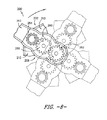
- FIG. 8 is a top view of a gear assembly for use with a spray arm assembly, along with contextual transparent portions of the spray arm assembly, illustrating movement of the gear assembly and spray arm assembly in accordance with one embodiment of the present disclosure
- FIG. 9 is a diagram illustrating travels paths of branches of a spray arm of a spray arm assembly in accordance with one embodiment of the present disclosure.
- the term “article” may refer to but need not be limited to dishes, pots, pans, silverware, and other cooking utensils and items that can be cleaned in a dishwashing appliance.
- the term “wash cycle” is intended to refer to one or more periods of time during which a dishwashing appliance operates while containing the articles to be washed and uses a detergent and water, preferably with agitation, to e.g., remove soil particles including food and other undesirable elements from the articles.
- the term “rinse cycle” is intended to refer to one or more periods of time in which the dishwashing appliance operates to remove residual soil, detergents, and other undesirable elements that were retained by the articles after completion of the wash cycle.
- wash fluid refers to a liquid used for washing and/or rinsing the articles and is typically made up of water that may include other additives such as detergent or other treatments.
- FIGS. 1 and 2 depict an exemplary domestic dishwasher or dishwashing appliance 100 that may be configured in accordance with aspects of the present disclosure.
- the dishwasher 100 includes a cabinet 102 having a tub 104 therein that defines a wash chamber 106 .
- the tub 104 includes a front opening (not shown) and a door 120 hinged at its bottom 122 for movement between a normally closed vertical position (shown in FIGS. 1 and 2 ), wherein the wash chamber 106 is sealed shut for washing operation, and a horizontal open position for loading and unloading of articles from the dishwasher.
- Latch 123 is used to lock and unlock door 120 for access to chamber 106 .
- Upper and lower guide rails 124 , 126 are mounted on tub side walls 128 and accommodate roller-equipped rack assemblies 130 and 132 .
- Each of the rack assemblies 130 , 132 is fabricated into lattice structures including a plurality of elongated members 134 (for clarity of illustration, not all elongated members making up assemblies 130 and 132 are shown in FIG. 2 ).
- Each rack 130 , 132 is adapted for movement between an extended loading position (not shown) in which the rack is substantially positioned outside the wash chamber 106 , and a retracted position (shown in FIGS. 1 and 2 ) in which the rack is located inside the wash chamber 106 . This is facilitated by rollers 135 and 139 , for example, mounted onto racks 130 and 132 , respectively.
- a silverware basket (not shown) may be removably attached to rack assembly 132 for placement of silverware, utensils, and the like, that are otherwise too small to be accommodated by the racks 130 , 132 .
- the dishwasher 100 further includes a lower spray-arm assembly 144 that is rotatably mounted within a lower region 146 of the wash chamber 106 and above a tub sump portion 142 so as to rotate in relatively close proximity to rack assembly 132 .
- a mid-level spray-arm assembly 148 is located in an upper region of the wash chamber 106 and may be located in close proximity to upper rack 130 .
- an upper spray assembly 150 may be located above the upper rack 130 .
- the lower and mid-level spray-arm assemblies 144 , 148 and the upper spray assembly 150 are fed by a fluid circulation assembly 152 for circulating water and dishwasher fluid in the tub 104 .
- the fluid circulation assembly 152 may include a pump 154 located in a machinery compartment 140 located below the bottom sump portion 142 of the tub 104 , as generally recognized in the art.
- Each spray-arm assembly 144 , 148 includes an arrangement of discharge ports or orifices for directing washing liquid onto dishes or other articles located in rack assemblies 130 and 132 .
- the arrangement of the discharge ports, also referred to as jets or apertures, in spray-arm assemblies 144 , 148 provides a rotational force by virtue of washing fluid flowing through the discharge ports.
- the resultant rotation of the lower spray-arm assembly 144 provides coverage of dishes and other dishwasher contents with a washing spray.
- the dishwasher 100 is further equipped with a controller 137 to regulate operation of the dishwasher 100 .
- the controller may include a memory and one or more microprocessors, such as a general or special purpose microprocessor operable to execute programming instructions or micro-control code associated with a cleaning cycle.
- the memory may represent random access memory such as DRAM, or read only memory such as ROM or FLASH.
- the processor executes programming instructions stored in memory.
- the memory may be a separate component from the processor or may be included onboard within the processor.
- the controller 137 may be positioned in a variety of locations throughout dishwasher 100 .
- the controller 137 may be located within a control panel area 121 of door 120 as shown.
- I/O input/output
- the controller 137 includes a user interface panel 136 through which a user may select various operational features and modes and monitor progress of the dishwasher 100 .
- the user interface 136 may represent a general purpose I/O (“GPIO”) device or functional block.
- GPIO general purpose I/O
- the user interface 136 may include input components, such as one or more of a variety of electrical, mechanical or electro-mechanical input devices including rotary dials, push buttons, and touch pads.
- the user interface 136 may include a display component, such as a digital or analog display device designed to provide operational feedback to a user.
- the user interface 136 may be in communication with the controller 137 via one or more signal lines or shared communication busses.
- a spray arm assembly 200 may be utilized in a dishwasher appliance 100 , and advantageously may provide sufficient wash fluid flow to the outer peripheral areas, and particularly the corners thereof, of the dishwasher appliance 100 .
- the rotational pattern of the spray arm assembly 200 generally and the branches and apertures thereof, as discussed herein, may efficiently and reliably provide wash fluid flow to the outer peripheral areas of the dishwasher appliance 100 .
- the spray arm assembly 200 is a mid-level spray arm assembly 148 .
- the spray arm assembly 200 may be a lower spray arm assembly 144 or may be utilized in the place of an upper spray assembly 150 , or may be utilized in any other suitable position within dishwasher appliance 100 .
- the spray arm assembly 200 may generally be in fluid communication with the fluid circulation assembly 152 to receive wash fluid therefrom. The wash fluid is then flowed through the spray arm assembly 200 and exhausted therefrom into the wash chamber 106 during operation of the dishwasher appliance 100 , such as during a wash or rinse cycle.
- Spray arm assembly 200 includes a spray arm 202 , a base conduit 204 , and an intermediate conduit 206 connecting the base conduit 204 and spray arm 202 .
- the base conduit 204 may be in fluid communication with the fluid circulation assembly 152 to receive wash fluid therefrom. This wash fluid may flow from the base conduit 204 through the intermediate conduit 206 to the spray arm 202 .
- the spray arm 202 may be rotatable about a central axis relative to the intermediate conduit 206
- the intermediate conduit 206 may be rotatable about a central axis relative to the base conduit 205 .
- the respective central axes may be generally parallel and offset from each other, such that a travel path for branches of the spray arm 202 provides wash fluid to the outer periphery of the wash chamber 106 .
- the tips of each branch may generally form a Reuleaux triangle.
- Spray arm 202 may include, for example, a plurality of branches 210 .
- the branches 210 may be connected to each other and arrayed about a center point 212 , as illustrated.
- Each branch 210 may define a passage 214 therethrough.
- each branch 210 may define one or more apertures 216 .
- Apertures 216 of a branch 210 may be in fluid communication with the passage 214 of that branch 210 , such that wash fluid may flow from the passage 214 through the apertures 216 to the wash chamber 106 .
- spray arm 202 may include three branches 210 . These branches 210 may be equidistantly arrayed about the center point 212 , which in the case of three branches 210 equates to 120 degrees apart. Apertures 216 may be spaced apart along the length of each branch 210 . Further, in exemplary embodiments, at least one aperture 216 may be defined proximate a tip 218 of each branch 210 . The tip 218 may be the farthest point on the branch 210 from the center point 212 .
- Center point 212 of the spray arm 202 may define a spray arm central axis 220 .
- the axis 220 may extend through the center point 212 perpendicularly to a plane defined by the branches 210 .
- the spray arm 202 may be rotatable about this axis 220 .
- Base conduit 204 may also define a passage 230 therethrough. Wash fluid may flow into the passage 230 from the fluid circulation assembly 152 , and from the passage 230 to the intermediate conduit 206 . Further, base conduit 204 may, as illustrated, define a base conduit central axis 232 . In some embodiments, as illustrated, the base conduit central axis 232 may extend through a center point of the base conduit 204 . The base conduit central axis 232 may extend generally parallel to the spray arm central axis 220 . Further, advantageously, the spray arm central axis 220 may be offset from the base conduit central axis 232 .
- Intermediate conduit 206 may further define a passage 240 therethrough.
- the passage 240 may be in fluid communication between the passage 230 and the passages 214 , such that wash fluid flowed to passage 230 can flow through passage 240 to passages 214 .
- the intermediate conduit 206 may be rotatable about the base conduit central axis 232 .
- the intermediate conduit 206 may include an upper casing portion 242 and a lower casing portion 244 , which may together define therebetween the passage 240 .
- the upper and lower casing portions 242 , 244 may be separate components which are connected together to form and define the intermediate conduit 206 .
- the upper and lower casing portions 242 , 244 may be integral, and thus integrally formed as a singular, unitary component.
- a pocket 243 may be defined in the upper casing portion and a pocket 245 may be defined in the lower casing portion 245 .
- These pockets 243 , 245 may advantageously accommodate bearings of a gear assembly of the spray arm assembly 200 as discussed herein.
- pocket 243 may in exemplary embodiments be coaxial with the spray arm central axis 220 such that central axis 220 extends through a centerpoint of the pocket 243
- pocket 245 may in exemplary embodiments be coaxial with the base conduit central axis 232 such that central axis 232 extends through a centerpoint of the pocket 245 .
- Intermediate conduit 206 may further include a first collar 300 and a second collar 310 .
- the first collar 300 may, for example, be connected to or an integral component of the upper casing portion 242 . Further, in exemplary embodiments, the first collar 300 may be coaxial with the base conduit central axis 232 such that central axis 232 extends through a centerpoint of the first collar 300 .
- the second collar 310 may, for example, be connected to or an integral component of the lower casing portion 244 . Further, in exemplary embodiments, the second collar 310 may be coaxial with the spray arm central axis 220 such that central axis 220 extends through a centerpoint of the second collar 310 .
- the first collar 300 may define a first opening 302 of the intermediate conduit 206 . Such first opening 302 may provide the fluid communication between the passage 240 and the passage 230 . Fluid may thus flow from passage 230 through first opening 302 into passage 240 .
- the second collar 310 may define a second opening 312 of the intermediate conduit 206 . Such second opening 312 may provide the fluid communication between the passage 240 and the passages 214 . Fluid may thus flow from passage 240 through second opening 312 into passages 214 .
- the first and second collars 300 , 310 may each have a stepped configuration.
- each collar 300 , 310 may include a first inner sidewall 304 , 314 , respectively, and a second inner sidewall 306 , 316 , respectively.
- a diameter 307 (such as a maximum diameter) of the second inner sidewall 306 may be less than a diameter 305 (such as a maximum diameter) of the first inner sidewall 304 .
- a diameter 317 (such as a maximum diameter) of the second inner sidewall 316 may be less than a diameter 315 (such as a maximum diameter) of the first inner sidewall 314 .
- a step 308 , 318 which as shown may be a radially-extending inner surface, may extend between each first inner sidewall 304 , 314 and associated second inner sidewall 306 , 316 .
- the intermediate conduit 206 may rotate about the base conduit central axis 232 , and the spray arm 202 by rotate about the spray arm central axis 220 , which may be offset from the base conduit central axis 232 .
- Such rotations may result in an advantageous travel path for the branches 210 and the apertures 216 thereof.
- Such travel path may allow the tips 218 of the branches 210 to approach the periphery, and in particular the peripheral corners, of the wash chamber 106 , such that wash fluid from the apertures 216 proximate the tips 218 can impart wash fluid to the corners and periphery.
- the tips 218 of the branches 210 may generally form a Reuleaux triangle.
- the tips 218 and movement thereof may be generally constrained by the geometries of a Reuleaux triangle.
- Respective apertures 216 of the branches 210 may similarly form, and thus be constrained by the geometries of, Reuleaux triangles.
- FIG. 9 illustrates exemplary travels paths 250 , 252 of tips 218 and apertures 216 , along with a comparative ideal Reuleaux triangle travel path 254 .
- the travels paths 250 , 252 may approximate Reuleaux triangle travel paths 254 , as shown, or follow Reuleaux triangle travel paths 254 .
- the tips 218 of the branches 210 in exemplary embodiments may be or approximate vertices of a Reuleaux triangle.
- fluid flow through the spray arm assembly 200 may cause rotation of the spray arm 202 about the spray arm central axis 220 and rotation of the intermediate conduit 206 about the base conduit central axis 232 .
- no external forces such as by a motor, etc., may cause such rotations.
- external forces from a motor or other suitable device may be applied, solely or in addition to the use of forces from the fluid flow, to cause such rotations.
- spray arm assembly 200 may further include a gear assembly 260 .
- the gear assembly 260 may facilitate the rotations of the spray arm assembly components 200 as discussed herein.
- gear assembly 260 may be disposed within the intermediate conduit 206 .
- Gear assembly 260 may include, for example, a first gear 262 rotatable about the base conduit central axis 232 .
- the axis 232 may for example extend through a centerpoint of the first gear 262 , such that a central axis of the first gear 262 is coaxial with the axis 232 .
- Gear assembly 260 may further include, for example, a second gear 264 rotatable about the spray arm central axis 220 .
- the axis 220 may for example extend through a centerpoint of the second gear 264 , such that a central axis of the second gear 264 is coaxial with the axis 220 .
- the gear assembly 260 may further include a third gear 266 rotatably connecting the first gear 262 and the second gear 264 . Accordingly, teeth of the third gear 266 may mesh with teeth of the first and second gears 262 , 264 , such that rotation of one gear causes rotation of the other two.
- the first gear 262 and second gear 264 may be rotatably connected, with no intervening gear, or additional gears may be utilized between the first gear 262 and second gear 264 .
- a gear ratio between the first gear 262 and the second gear 264 is approximately 1 to ⁇ 0.75. Such ratio may facilitate the advantageous movement of the branches 210 , and the tips 218 and apertures 216 thereof, as discussed herein.
- a gear ratio between the first gear 262 and the third gear 266 may be approximately 1 to 1
- a gear ration between the third gear 266 and the second gear 264 may be approximately 1 to 0.75.
- any suitable gear ratios between any of the gears of gear assembly 260 may be utilized.
- the first gear 262 and second gear 264 are generally hollow.
- the central portions of such gears may be hollow, and openings may be defined between the teeth of the gears. This advantageously allows for the flow of wash fluid through these gears, i.e. from the central portion through the openings between the teeth or vice versa, which allows for the rotations of the various components of the spray arm assembly 200 as discussed herein and reduces or prevents binding. Wash fluid may thus, for example, flow through first gear 262 from the passage 230 , and through second gear 264 to the passages 214 .
- wash fluid may be free to flow into the first gear 262 from the passage 230 of the base conduit 204 (such as in a direction along the base conduit central axis 232 ), out of the first gear 262 in a generally radial direction between the teeth thereof, into the second gear 264 in a generally radial direction between the teeth thereof, and from the second gear 264 into the passages 214 of the spray arm 202 .
- the first gear 262 may generally be fixedly connected to the base conduit 204
- the second gear 264 may generally be fixedly connected to the spray arm 202 . Since the base conduit 204 is generally fixed to the fluid circulation assembly 152 , rotation of the gear assembly 260 may thus cause rotation of the spray arm 202 and the intermediate conduit 206 as discussed herein.
- gear assembly 260 may include a first hollow bearing 320 and a second hollow bearing 330 .
- First hollow bearing 320 may be fixedly connected to the first gear 262 , and may extend from the first gear 262 axially through the first opening 302 to the base conduit 204 .
- the first hollow bearing 320 may, for example, be coaxial with the axis 232 .
- the first hollow bearing 320 may further be fixedly connected to the base conduit 204 .
- first hollow bearing 320 may be integral, and thus integrally formed as a single, unitary component, with first gear 262 .
- first hollow bearing 320 may be a separate component that is connected to the first gear 262 .
- Second hollow bearing 330 may be fixedly connected to the second gear 264 , and may extend from the second gear 264 axially through the second opening 312 to the spray arm 202 .
- the second hollow bearing 330 may further be fixedly connected to the spray arm 202 .
- the second hollow bearing 330 may, for example, be coaxial with the axis 220 .
- second hollow bearing 330 may be integral, and thus integrally formed as a single, unitary component, with second gear 264 .
- second hollow bearing 330 may be a separate component that is connected to the second gear 264 .
- each hollow bearing 320 , 330 may include a body 322 , 332 and a flange 324 , 334 which extends from the body 322 , 332 .
- a diameter 325 , 335 (such as a maximum diameter defined by the outer surface of the flange 324 , 334 ) of each flange 324 , 334 may be less than a diameter 323 , 333 (such as a maximum diameter defined by the outer surface of the body 322 , 332 ) of the associated body 322 , 332 .
- particular clearances may be defined between the hollow bearings 320 , 330 and associated collars 300 , 310 .
- Such clearances may advantageously minimize stresses and potential binding in the spray arm assembly 200 during use.
- the clearances are advantageously sufficiently large to minimize stresses and potential binding, but sufficiently small to prevent excess movement of the bearings 320 , 330 and gears 262 , 264 which could cause damage thereto.
- the clearances account for stresses due to the various reactionary forces from the weights of the spray arm components and the liquid being flowed therethrough.
- Such clearance is defined, as shown, between an inner surface of the collar and a neighboring outer surface of the hollow bearing.
- such radial clearance R 1 of between about 0.005 inches and about 0.020 inches, such as between about 0.010 inches and 0.015 inches, such as about 0.010 inches, such as 0.010 inches, may be defined between each body 322 , 332 and associated second inner sidewall 306 , 316 and between each flange 324 , 334 and associated first inner sidewall 304 , 314 .
- gear assembly 260 may further include additional solid bearings disposed between the gears and the casing portions of the intermediate conduit 206 .
- a first solid bearing 340 may be disposed between the first gear 262 and the lower casing portion 244
- a second solid bearing 350 may be disposed between the second gear 264 and the upper casing portion 242 .
- These bearings 340 , 350 may further facilitate rotation of the gear assembly and reduce or eliminate binding during operation thereof.
- First solid bearing 340 may be fixedly connected to the first gear 262 . Further, as shown, first solid bearing 340 may be coaxial with axis 232 . First solid bearing 340 may be integral, and thus integrally formed as a single, unitary component, with first gear 262 , or, as shown, may be a separate component that is connected to the first gear 262 . Second solid bearing 350 may be fixedly connected to the second gear 264 . Further, as shown, second solid bearing 350 may be coaxial with axis 220 . Second solid bearing 350 may be integral, and thus integrally formed as a single, unitary component, with second gear 264 , or, as shown, may be a separate component that is connected to the second gear 264 .
- first solid bearing 340 and second solid bearing 350 may each include a body 342 , 352 and a support post 344 , 354 extending from the associated body 342 , 352 , such as along the axial direction.
- Each support port 344 , 354 may extend into the associated pocket 245 , 243 of the associated casing portion 242 , 244 .
- particular clearances and sizes may be defined for the solid bearings 340 , 350 , and in particular the support posts 344 , 354 thereof, relative to the associated pocket 245 , 243 of the associated casing portion 242 , 244 .
- Such clearances may advantageously minimize stresses and potential binding in the spray arm assembly 200 during use.
- the clearances are advantageously sufficiently large to minimize stresses and potential binding, but sufficiently small to prevent excess movement of the bearings 340 , 350 and gears 262 , 264 which could cause damage thereto.
- the clearances account for stresses due to the various reactionary forces from the weights of the spray arm components and the liquid being flowed therethrough.
- each support post 344 , 354 may have a diameter 345 , 355 (such as a maximum diameter) of between 0.1 inches and 0.15 inches, such as between 0.11 inches and 0.13 inches, such as between 0.115 inches and 0.125 inches, such as 0.12 inches.
- a radial (i.e. perpendicular to associated axis 220 or 232 ) clearance R 2 of between about 0.005 inches and about 0.020 inches, such as between about 0.010 inches and 0.015 inches, such as about 0.010 inches, such as 0.010 inches, is defined between the support post 344 and the pocket 245 and between the support post 354 and the pocket 243 .
- Such clearance is defined, as shown, between an inner surface of the pocket and a neighboring outer surface of the support post.
- Such clearance is defined, as shown, between an inner surface of the pocket and a neighboring outer surface of the support post.
- the gears 262 , 264 , hollow bearings 320 , 330 , and solid bearings 340 , 350 are formed from suitable plastics, such as acetals. Alternatively, however, other suitable materials may be utilized.
- FIG. 8 illustrates movement of the gear assembly 260 during operation of the spray arm assembly 200 and dishwasher appliance 100 generally. Rotational directions of the gears 262 , 264 , 266 are illustrated, along with rotation of the spray arm 202 about the spray arm central axis 220 and rotation of the intermediate conduit 206 about the base conduit central axis 232 . (Only portions of the spray arm 202 and intermediate conduit 206 are illustrated, for illustrative purposes only.)
- spray arm assembly 200 may further include a counterweight 280 .
- the counterweight 280 may balance the spray arm assembly 200 , particularly during rotation of both the spray arm 202 and the intermediate conduit 206 about the offset axes 220 , 232 , respectively.
- counterweight 280 may be generally arcuate.
- the counterweight 280 may be connected to the intermediate conduit 206 , such as to an auxiliary arm 282 of the intermediate conduit 206 .
- auxiliary arm 282 may define a passage 284 therethrough and one or more apertures 286 defined therein and in fluid communication with the passage 284 .
- a portion of the wash fluid may flow from the passage 240 into passage 284 , rather than into passages 214 , and may then be exhausted from the passage 284 through the apertures 286 .
- at least one aperture 286 may be defined proximate a tip 288 of the auxiliary arm 282 , which may extend beyond the counterweight 280 .
- the apertures 286 may, for example, have generally circular travel paths that supplement the travel paths of the apertures 216 .
Landscapes
- Washing And Drying Of Tableware (AREA)
Abstract
Description
- The present disclosure relates generally to dishwasher appliances, and more particularly to improved spray arm assemblies for dishwasher appliances.
- Dishwasher appliances generally include a tub that defines a wash compartment. Rack assemblies can be mounted within the wash compartment of the tub for receipt of articles for washing. During wash and rinse cycles, spray assemblies within the wash compartment can apply or direct wash fluid (e.g. various combinations of water and detergent along with optional additives) towards articles disposed within the rack assemblies in order to clean such articles.
- Multiple spray assemblies can be provided including e.g., a lower spray arm assembly mounted to the tub at a bottom of the wash compartment, a mid-level spray arm assembly mounted to one of the rack assemblies, and/or an upper spray assembly mounted to the tub at a top of the wash compartment. Other configurations may be used as well.
- One limitation of many currently known spray arm assemblies is the geometry of the spray arm assemblies relative to the geometry of the dishwasher appliance interior. Most known spray arm assemblies utilize a generally circular geometry. For example, an arm of a spray arm assembly may rotate in a circle, and jets or apertures defined in the arm may emit wash fluid from the arm in this circular pattern. However, the cross-sectional interior geometry of most currently known dishwasher appliances is square or rectangular. Accordingly, the corners of such dishwasher appliance, and the articles located therein, may not be sufficiently reached by wash fluid. This can result in these articles not being properly cleaned during operation of the dishwasher appliance.
- Attempts have been made to provide sufficient wash fluid in the corners of dishwasher appliances. For example, various jets may be angled towards the outer periphery of a dishwasher appliance interior, in an attempt to direct wash fluid towards the corners. Such designs, however, are typically inefficient, requiring dedicated wash fluid streams which are only effective within minimal windows. Other attempts have utilized pivoting supports or outer peripheral tracks to guide the spray arm assemblies. Such designs, however, are typically complex, expensive, and ineffective.
- More recently, attempts have been made to utilize various cantilevered spray arm component designs. However, these designs are subject to considerable stresses due to the various reactionary forces from the weights of the spray arm components and the liquid being flowed therethrough.
- Accordingly, improved dishwasher appliances and associated spray arm assemblies are desired in the art. In particular, improved spray arm assembly designs which provide sufficient wash fluid flow to the outer peripheral areas, and particularly the corners thereof, of dishwasher appliances would be advantageous. Further, improved spray arm assembly designs which minimize stresses and potential binding of rotating components during operation would be advantageous.
- Aspects and advantages of the invention will be set forth in part in the following description, or may be obvious from the description, or may be learned through practice of the invention.
- In accordance with one embodiment of the present disclosure, a spray arm assembly for a dishwasher appliance is disclosed. The spray arm assembly includes a spray arm including a plurality of branches connected to each other and arrayed about a center point, each of the plurality of branches defining a passage therethrough and an aperture in fluid communication with the passage. The center point defines a spray arm central axis. The spray arm is rotatable about the spray arm central axis. The spray arm assembly further includes a base conduit defining a passage therethrough, the base conduit defining a base conduit central axis. The base conduit central axis is offset from the spray arm central axis. The spray arm assembly further includes an intermediate conduit connecting the base conduit and the spray arm, the intermediate conduit defining a passage in fluid communication between the passage of the base conduit and the passages of the plurality of branches. The intermediate conduit is rotatable about the base conduit central axis. The intermediate conduit includes a first collar that defines a first opening and a second collar that defines a second opening, the first opening providing the fluid communication between the passage of the intermediate conduit and the passage of the base conduit, the second opening providing the fluid communication between the passage of the intermediate conduit and the passages of the plurality of branches. The spray arm assembly further includes a gear assembly at least partially disposed within the intermediate conduit. The gear assembly includes a first gear rotatable about the base conduit central axis and a second gear rotatable about the spray arm central axis. The gear assembly further includes a first hollow bearing extending from the first gear through the first opening and a second hollow bearing extending from the second gear through the second opening. A radial clearance of between about 0.005 inches and about 0.020 inches is defined between the first hollow bearing and the first collar and between the second hollow bearing and the second collar.
- In accordance with one embodiment of the present disclosure, a spray arm assembly for a dishwasher appliance is disclosed. The spray arm assembly includes a spray arm including a plurality of branches connected to each other and arrayed about a center point, each of the plurality of branches defining a passage therethrough and an aperture in fluid communication with the passage. The center point defines a spray arm central axis. The spray arm is rotatable about the spray arm central axis. The spray arm assembly further includes a base conduit defining a passage therethrough, the base conduit defining a base conduit central axis. The base conduit central axis is offset from the spray arm central axis. The spray arm assembly further includes an intermediate conduit connecting the base conduit and the spray arm, the intermediate conduit defining a passage in fluid communication between the passage of the base conduit and the passages of the plurality of branches. The intermediate conduit is rotatable about the base conduit central axis. The intermediate conduit comprising an upper casing portion and a lower casing portion. The spray arm assembly further includes a gear assembly at least partially disposed within the intermediate conduit. The gear assembly includes a first gear rotatable about the base conduit central axis and a second gear rotatable about the spray arm central axis. The gear assembly further includes a first solid bearing disposed between the first gear and the lower casing portion and a second solid bearing disposed between the second gear and the upper casing portion. The first solid bearing and second solid bearing each include a body and a support post extending from the body.
- These and other features, aspects and advantages of the present invention will become better understood with reference to the following description and appended claims. The accompanying drawings, which are incorporated in and constitute a part of this specification, illustrate embodiments of the invention and, together with the description, serve to explain the principles of the invention.
- A full and enabling disclosure of the present invention, including the best mode thereof, directed to one of ordinary skill in the art, is set forth in the specification, which makes reference to the appended figures, in which:
-
FIG. 1 provides a front view of a dishwasher appliance in accordance with one embodiment of the present disclosure; -
FIG. 2 is a cross-sectional view of a dishwasher appliance in accordance with one embodiment of the present disclosure; -
FIG. 3 is a top perspective view of a spray arm assembly in accordance with one embodiment of the present disclosure; -
FIG. 4 is a bottom view of a spray arm assembly in accordance with one embodiment of the present disclosure; -
FIG. 5 is a cross-sectional view of a portion of a spray arm assembly in accordance with one embodiment of the present disclosure; -
FIG. 6 is a perspective view of a gear, hollow bearing and solid bearing in accordance with one embodiment of the present disclosure; -
FIG. 7 is a perspective cross-sectional view of a gear, hollow bearing and solid bearing in accordance with one embodiment of the present disclosure; -
FIG. 8 is a top view of a gear assembly for use with a spray arm assembly, along with contextual transparent portions of the spray arm assembly, illustrating movement of the gear assembly and spray arm assembly in accordance with one embodiment of the present disclosure; and -
FIG. 9 is a diagram illustrating travels paths of branches of a spray arm of a spray arm assembly in accordance with one embodiment of the present disclosure. - Reference now will be made in detail to embodiments of the invention, one or more examples of which are illustrated in the drawings. Each example is provided by way of explanation of the invention, not limitation of the invention. In fact, it will be apparent to those skilled in the art that various modifications and variations can be made in the present invention without departing from the scope or spirit of the invention. For instance, features illustrated or described as part of one embodiment can be used with another embodiment to yield a still further embodiment. Thus, it is intended that the present invention covers such modifications and variations as come within the scope of the appended claims and their equivalents.
- As used herein, the term “article” may refer to but need not be limited to dishes, pots, pans, silverware, and other cooking utensils and items that can be cleaned in a dishwashing appliance. The term “wash cycle” is intended to refer to one or more periods of time during which a dishwashing appliance operates while containing the articles to be washed and uses a detergent and water, preferably with agitation, to e.g., remove soil particles including food and other undesirable elements from the articles. The term “rinse cycle” is intended to refer to one or more periods of time in which the dishwashing appliance operates to remove residual soil, detergents, and other undesirable elements that were retained by the articles after completion of the wash cycle. The term “wash fluid” refers to a liquid used for washing and/or rinsing the articles and is typically made up of water that may include other additives such as detergent or other treatments.
-
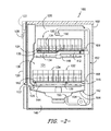
FIGS. 1 and 2 depict an exemplary domestic dishwasher ordishwashing appliance 100 that may be configured in accordance with aspects of the present disclosure. For the particular embodiment ofFIGS. 1 and 2 , thedishwasher 100 includes acabinet 102 having atub 104 therein that defines awash chamber 106. Thetub 104 includes a front opening (not shown) and adoor 120 hinged at itsbottom 122 for movement between a normally closed vertical position (shown inFIGS. 1 and 2), wherein thewash chamber 106 is sealed shut for washing operation, and a horizontal open position for loading and unloading of articles from the dishwasher.Latch 123 is used to lock and unlockdoor 120 for access tochamber 106. - Upper and
lower guide rails tub side walls 128 and accommodate roller-equippedrack assemblies rack assemblies assemblies FIG. 2 ). Eachrack wash chamber 106, and a retracted position (shown inFIGS. 1 and 2 ) in which the rack is located inside thewash chamber 106. This is facilitated byrollers racks assembly 132 for placement of silverware, utensils, and the like, that are otherwise too small to be accommodated by theracks - The
dishwasher 100 further includes a lower spray-arm assembly 144 that is rotatably mounted within alower region 146 of thewash chamber 106 and above atub sump portion 142 so as to rotate in relatively close proximity to rackassembly 132. A mid-level spray-arm assembly 148 is located in an upper region of thewash chamber 106 and may be located in close proximity toupper rack 130. Additionally, anupper spray assembly 150 may be located above theupper rack 130. - The lower and mid-level spray-
arm assemblies upper spray assembly 150 are fed by afluid circulation assembly 152 for circulating water and dishwasher fluid in thetub 104. Thefluid circulation assembly 152 may include apump 154 located in amachinery compartment 140 located below thebottom sump portion 142 of thetub 104, as generally recognized in the art. Each spray-arm assembly rack assemblies arm assemblies arm assembly 144 provides coverage of dishes and other dishwasher contents with a washing spray. - The
dishwasher 100 is further equipped with acontroller 137 to regulate operation of thedishwasher 100. The controller may include a memory and one or more microprocessors, such as a general or special purpose microprocessor operable to execute programming instructions or micro-control code associated with a cleaning cycle. The memory may represent random access memory such as DRAM, or read only memory such as ROM or FLASH. In one embodiment, the processor executes programming instructions stored in memory. The memory may be a separate component from the processor or may be included onboard within the processor. - The
controller 137 may be positioned in a variety of locations throughoutdishwasher 100. In the illustrated embodiment, thecontroller 137 may be located within acontrol panel area 121 ofdoor 120 as shown. In such an embodiment, input/output (“I/O”) signals may be routed between the control system and various operational components ofdishwasher 100 along wiring harnesses that may be routed through thebottom 122 ofdoor 120. Typically, thecontroller 137 includes auser interface panel 136 through which a user may select various operational features and modes and monitor progress of thedishwasher 100. In one embodiment, theuser interface 136 may represent a general purpose I/O (“GPIO”) device or functional block. In one embodiment, theuser interface 136 may include input components, such as one or more of a variety of electrical, mechanical or electro-mechanical input devices including rotary dials, push buttons, and touch pads. Theuser interface 136 may include a display component, such as a digital or analog display device designed to provide operational feedback to a user. Theuser interface 136 may be in communication with thecontroller 137 via one or more signal lines or shared communication busses. - Referring now to
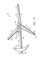
FIGS. 3 through 8 , various embodiments of aspray arm assembly 200 are illustrated. Aspray arm assembly 200 may be utilized in adishwasher appliance 100, and advantageously may provide sufficient wash fluid flow to the outer peripheral areas, and particularly the corners thereof, of thedishwasher appliance 100. In particular, the rotational pattern of thespray arm assembly 200 generally and the branches and apertures thereof, as discussed herein, may efficiently and reliably provide wash fluid flow to the outer peripheral areas of thedishwasher appliance 100. - In exemplary embodiments, the
spray arm assembly 200 is a mid-levelspray arm assembly 148. Alternatively, thespray arm assembly 200 may be a lowerspray arm assembly 144 or may be utilized in the place of anupper spray assembly 150, or may be utilized in any other suitable position withindishwasher appliance 100. Thespray arm assembly 200 may generally be in fluid communication with thefluid circulation assembly 152 to receive wash fluid therefrom. The wash fluid is then flowed through thespray arm assembly 200 and exhausted therefrom into thewash chamber 106 during operation of thedishwasher appliance 100, such as during a wash or rinse cycle. -
Spray arm assembly 200 includes aspray arm 202, abase conduit 204, and anintermediate conduit 206 connecting thebase conduit 204 andspray arm 202. Thebase conduit 204 may be in fluid communication with thefluid circulation assembly 152 to receive wash fluid therefrom. This wash fluid may flow from thebase conduit 204 through theintermediate conduit 206 to thespray arm 202. Further, as discussed, thespray arm 202 may be rotatable about a central axis relative to theintermediate conduit 206, and theintermediate conduit 206 may be rotatable about a central axis relative to the base conduit 205. The respective central axes may be generally parallel and offset from each other, such that a travel path for branches of thespray arm 202 provides wash fluid to the outer periphery of thewash chamber 106. For example, in exemplary embodiments, the tips of each branch may generally form a Reuleaux triangle. -
Spray arm 202 may include, for example, a plurality ofbranches 210. Thebranches 210 may be connected to each other and arrayed about acenter point 212, as illustrated. Eachbranch 210 may define apassage 214 therethrough. Further, eachbranch 210 may define one ormore apertures 216.Apertures 216 of abranch 210 may be in fluid communication with thepassage 214 of thatbranch 210, such that wash fluid may flow from thepassage 214 through theapertures 216 to thewash chamber 106. - In exemplary embodiments as illustrated,
spray arm 202 may include threebranches 210. Thesebranches 210 may be equidistantly arrayed about thecenter point 212, which in the case of threebranches 210 equates to 120 degrees apart.Apertures 216 may be spaced apart along the length of eachbranch 210. Further, in exemplary embodiments, at least oneaperture 216 may be defined proximate atip 218 of eachbranch 210. Thetip 218 may be the farthest point on thebranch 210 from thecenter point 212. -
Center point 212 of thespray arm 202 may define a spray armcentral axis 220. Theaxis 220 may extend through thecenter point 212 perpendicularly to a plane defined by thebranches 210. Thespray arm 202 may be rotatable about thisaxis 220. -
Base conduit 204 may also define apassage 230 therethrough. Wash fluid may flow into thepassage 230 from thefluid circulation assembly 152, and from thepassage 230 to theintermediate conduit 206. Further,base conduit 204 may, as illustrated, define a base conduitcentral axis 232. In some embodiments, as illustrated, the base conduitcentral axis 232 may extend through a center point of thebase conduit 204. The base conduitcentral axis 232 may extend generally parallel to the spray armcentral axis 220. Further, advantageously, the spray armcentral axis 220 may be offset from the base conduitcentral axis 232. -
Intermediate conduit 206 may further define apassage 240 therethrough. Thepassage 240 may be in fluid communication between thepassage 230 and thepassages 214, such that wash fluid flowed topassage 230 can flow throughpassage 240 topassages 214. Theintermediate conduit 206 may be rotatable about the base conduitcentral axis 232. - In exemplary embodiments, the
intermediate conduit 206 may include anupper casing portion 242 and alower casing portion 244, which may together define therebetween thepassage 240. As shown, the upper andlower casing portions intermediate conduit 206. Alternatively, the upper andlower casing portions pocket 243 may be defined in the upper casing portion and apocket 245 may be defined in thelower casing portion 245. Thesepockets spray arm assembly 200 as discussed herein. Notably,pocket 243 may in exemplary embodiments be coaxial with the spray armcentral axis 220 such thatcentral axis 220 extends through a centerpoint of thepocket 243, andpocket 245 may in exemplary embodiments be coaxial with the base conduitcentral axis 232 such thatcentral axis 232 extends through a centerpoint of thepocket 245. -
Intermediate conduit 206 may further include afirst collar 300 and asecond collar 310. Thefirst collar 300 may, for example, be connected to or an integral component of theupper casing portion 242. Further, in exemplary embodiments, thefirst collar 300 may be coaxial with the base conduitcentral axis 232 such thatcentral axis 232 extends through a centerpoint of thefirst collar 300. Thesecond collar 310 may, for example, be connected to or an integral component of thelower casing portion 244. Further, in exemplary embodiments, thesecond collar 310 may be coaxial with the spray armcentral axis 220 such thatcentral axis 220 extends through a centerpoint of thesecond collar 310. - The
first collar 300 may define afirst opening 302 of theintermediate conduit 206. Suchfirst opening 302 may provide the fluid communication between thepassage 240 and thepassage 230. Fluid may thus flow frompassage 230 throughfirst opening 302 intopassage 240. Thesecond collar 310 may define asecond opening 312 of theintermediate conduit 206. Suchsecond opening 312 may provide the fluid communication between thepassage 240 and thepassages 214. Fluid may thus flow frompassage 240 throughsecond opening 312 intopassages 214. - The first and
second collars collar inner sidewall inner sidewall inner sidewall 306 may be less than a diameter 305 (such as a maximum diameter) of the firstinner sidewall 304. A diameter 317 (such as a maximum diameter) of the secondinner sidewall 316 may be less than a diameter 315 (such as a maximum diameter) of the firstinner sidewall 314. Astep inner sidewall inner sidewall - As discussed, during operation of the
spray arm assembly 200, rotation of two separate components about offset parallel axes may occur. Theintermediate conduit 206 may rotate about the base conduitcentral axis 232, and thespray arm 202 by rotate about the spray armcentral axis 220, which may be offset from the base conduitcentral axis 232. Such rotations may result in an advantageous travel path for thebranches 210 and theapertures 216 thereof. Such travel path may allow thetips 218 of thebranches 210 to approach the periphery, and in particular the peripheral corners, of thewash chamber 106, such that wash fluid from theapertures 216 proximate thetips 218 can impart wash fluid to the corners and periphery. - In exemplary embodiments, the
tips 218 of thebranches 210 may generally form a Reuleaux triangle. In other words, thetips 218 and movement thereof may be generally constrained by the geometries of a Reuleaux triangle.Respective apertures 216 of thebranches 210 may similarly form, and thus be constrained by the geometries of, Reuleaux triangles.FIG. 9 illustratesexemplary travels paths tips 218 andapertures 216, along with a comparative ideal Reuleauxtriangle travel path 254. Thetravels paths triangle travel paths 254, as shown, or follow Reuleauxtriangle travel paths 254. It further follows that thetips 218 of thebranches 210 in exemplary embodiments may be or approximate vertices of a Reuleaux triangle. - Notably, in exemplary embodiments, fluid flow through the
spray arm assembly 200 may cause rotation of thespray arm 202 about the spray armcentral axis 220 and rotation of theintermediate conduit 206 about the base conduitcentral axis 232. In these embodiments, no external forces, such as by a motor, etc., may cause such rotations. Alternatively, however, external forces from a motor or other suitable device may be applied, solely or in addition to the use of forces from the fluid flow, to cause such rotations. - In exemplary embodiments, as illustrated in
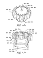
FIGS. 5 through 8 ,spray arm assembly 200 may further include agear assembly 260. Thegear assembly 260 may facilitate the rotations of the sprayarm assembly components 200 as discussed herein. As illustrated,gear assembly 260 may be disposed within theintermediate conduit 206.Gear assembly 260 may include, for example, afirst gear 262 rotatable about the base conduitcentral axis 232. Theaxis 232 may for example extend through a centerpoint of thefirst gear 262, such that a central axis of thefirst gear 262 is coaxial with theaxis 232.Gear assembly 260 may further include, for example, asecond gear 264 rotatable about the spray armcentral axis 220. Theaxis 220 may for example extend through a centerpoint of thesecond gear 264, such that a central axis of thesecond gear 264 is coaxial with theaxis 220. In exemplary embodiments, thegear assembly 260 may further include athird gear 266 rotatably connecting thefirst gear 262 and thesecond gear 264. Accordingly, teeth of thethird gear 266 may mesh with teeth of the first andsecond gears first gear 262 andsecond gear 264 may be rotatably connected, with no intervening gear, or additional gears may be utilized between thefirst gear 262 andsecond gear 264. - In exemplary embodiments, a gear ratio between the
first gear 262 and thesecond gear 264 is approximately 1 to −0.75. Such ratio may facilitate the advantageous movement of thebranches 210, and thetips 218 andapertures 216 thereof, as discussed herein. For example, when athird gear 266 is utilized, a gear ratio between thefirst gear 262 and thethird gear 266 may be approximately 1 to 1, and a gear ration between thethird gear 266 and thesecond gear 264 may be approximately 1 to 0.75. Alternatively, however, any suitable gear ratios between any of the gears ofgear assembly 260 may be utilized. - As further illustrated in
FIG. 5 , in exemplary embodiments, thefirst gear 262 andsecond gear 264 are generally hollow. For example, as illustrated, the central portions of such gears may be hollow, and openings may be defined between the teeth of the gears. This advantageously allows for the flow of wash fluid through these gears, i.e. from the central portion through the openings between the teeth or vice versa, which allows for the rotations of the various components of thespray arm assembly 200 as discussed herein and reduces or prevents binding. Wash fluid may thus, for example, flow throughfirst gear 262 from thepassage 230, and throughsecond gear 264 to thepassages 214. For example, wash fluid may be free to flow into thefirst gear 262 from thepassage 230 of the base conduit 204 (such as in a direction along the base conduit central axis 232), out of thefirst gear 262 in a generally radial direction between the teeth thereof, into thesecond gear 264 in a generally radial direction between the teeth thereof, and from thesecond gear 264 into thepassages 214 of thespray arm 202. - The
first gear 262 may generally be fixedly connected to thebase conduit 204, and thesecond gear 264 may generally be fixedly connected to thespray arm 202. Since thebase conduit 204 is generally fixed to thefluid circulation assembly 152, rotation of thegear assembly 260 may thus cause rotation of thespray arm 202 and theintermediate conduit 206 as discussed herein. - For example, bearings may be provided which fixedly connect the
first gear 262 to thebase conduit 204 and thesecond gear 264 to thespray arm 202. As shown,gear assembly 260 may include a firsthollow bearing 320 and a secondhollow bearing 330. Firsthollow bearing 320 may be fixedly connected to thefirst gear 262, and may extend from thefirst gear 262 axially through thefirst opening 302 to thebase conduit 204. As shown, the firsthollow bearing 320 may, for example, be coaxial with theaxis 232. The firsthollow bearing 320 may further be fixedly connected to thebase conduit 204. In exemplary embodiments, firsthollow bearing 320 may be integral, and thus integrally formed as a single, unitary component, withfirst gear 262. Alternatively, however, firsthollow bearing 320 may be a separate component that is connected to thefirst gear 262. Secondhollow bearing 330 may be fixedly connected to thesecond gear 264, and may extend from thesecond gear 264 axially through thesecond opening 312 to thespray arm 202. The secondhollow bearing 330 may further be fixedly connected to thespray arm 202. As shown, the secondhollow bearing 330 may, for example, be coaxial with theaxis 220. In exemplary embodiments, secondhollow bearing 330 may be integral, and thus integrally formed as a single, unitary component, withsecond gear 264. Alternatively, however, secondhollow bearing 330 may be a separate component that is connected to thesecond gear 264. - In exemplary embodiments, each
hollow bearing body 322, 332 and aflange 324, 334 which extends from thebody 322, 332. A diameter 325, 335 (such as a maximum diameter defined by the outer surface of theflange 324, 334) of eachflange 324, 334 may be less than a diameter 323, 333 (such as a maximum diameter defined by the outer surface of thebody 322, 332) of the associatedbody 322, 332. - In exemplary embodiments, particular clearances may be defined between the
hollow bearings collars spray arm assembly 200 during use. The clearances are advantageously sufficiently large to minimize stresses and potential binding, but sufficiently small to prevent excess movement of thebearings - For example, in exemplary embodiments, a radial (i.e. perpendicular to associated
axis 220 or 232) clearance of between about 0.005 inches and about 0.020 inches, such as between about 0.010 inches and 0.015 inches, such as about 0.010 inches, such as 0.010 inches, is defined between the firsthollow bearing 320 and thefirst collar 300 and between the secondhollow bearing 320 and thesecond collar 310. The term “about”, as utilized herein, means within a tolerance of plus or minus 0.005 inches. Such clearance is defined, as shown, between an inner surface of the collar and a neighboring outer surface of the hollow bearing. More specifically, in exemplary embodiments, such radial clearance R1 of between about 0.005 inches and about 0.020 inches, such as between about 0.010 inches and 0.015 inches, such as about 0.010 inches, such as 0.010 inches, may be defined between eachbody 322, 332 and associated secondinner sidewall flange 324, 334 and associated firstinner sidewall - In exemplary embodiments,
gear assembly 260 may further include additional solid bearings disposed between the gears and the casing portions of theintermediate conduit 206. For example, a firstsolid bearing 340 may be disposed between thefirst gear 262 and thelower casing portion 244, and a secondsolid bearing 350 may be disposed between thesecond gear 264 and theupper casing portion 242. Thesebearings - First
solid bearing 340 may be fixedly connected to thefirst gear 262. Further, as shown, firstsolid bearing 340 may be coaxial withaxis 232. Firstsolid bearing 340 may be integral, and thus integrally formed as a single, unitary component, withfirst gear 262, or, as shown, may be a separate component that is connected to thefirst gear 262. Secondsolid bearing 350 may be fixedly connected to thesecond gear 264. Further, as shown, secondsolid bearing 350 may be coaxial withaxis 220. Secondsolid bearing 350 may be integral, and thus integrally formed as a single, unitary component, withsecond gear 264, or, as shown, may be a separate component that is connected to thesecond gear 264. - In exemplary embodiments as shown, the first
solid bearing 340 and secondsolid bearing 350 may each include abody support post body support port pocket casing portion - In exemplary embodiments, particular clearances and sizes may be defined for the
solid bearings pocket casing portion spray arm assembly 200 during use. The clearances are advantageously sufficiently large to minimize stresses and potential binding, but sufficiently small to prevent excess movement of thebearings - For example, in some exemplary embodiments, each
support post diameter 345, 355 (such as a maximum diameter) of between 0.1 inches and 0.15 inches, such as between 0.11 inches and 0.13 inches, such as between 0.115 inches and 0.125 inches, such as 0.12 inches. Additionally or alternatively, a radial (i.e. perpendicular to associatedaxis 220 or 232) clearance R2 of between about 0.005 inches and about 0.020 inches, such as between about 0.010 inches and 0.015 inches, such as about 0.010 inches, such as 0.010 inches, is defined between thesupport post 344 and thepocket 245 and between thesupport post 354 and thepocket 243. Such clearance is defined, as shown, between an inner surface of the pocket and a neighboring outer surface of the support post. Additionally or alternatively, an axial (i.e. parallel to associatedaxis 220 or 232) clearance A1 of between about 0.005 inches and about 0.020 inches, such as between about 0.010 inches and 0.015 inches, such as about 0.010 inches, such as 0.010 inches, is defined between thesupport post 344 and thepocket 245 and between thesupport post 354 and thepocket 243. Such clearance is defined, as shown, between an inner surface of the pocket and a neighboring outer surface of the support post. - In exemplary embodiments, the
gears hollow bearings solid bearings -
FIG. 8 illustrates movement of thegear assembly 260 during operation of thespray arm assembly 200 anddishwasher appliance 100 generally. Rotational directions of thegears spray arm 202 about the spray armcentral axis 220 and rotation of theintermediate conduit 206 about the base conduitcentral axis 232. (Only portions of thespray arm 202 andintermediate conduit 206 are illustrated, for illustrative purposes only.) - Referring again to
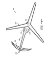
FIGS. 3 and 4 , in some embodiments,spray arm assembly 200 may further include acounterweight 280. Thecounterweight 280 may balance thespray arm assembly 200, particularly during rotation of both thespray arm 202 and theintermediate conduit 206 about the offsetaxes counterweight 280 may be generally arcuate. Thecounterweight 280 may be connected to theintermediate conduit 206, such as to anauxiliary arm 282 of theintermediate conduit 206. Further,auxiliary arm 282 may define apassage 284 therethrough and one ormore apertures 286 defined therein and in fluid communication with thepassage 284. A portion of the wash fluid may flow from thepassage 240 intopassage 284, rather than intopassages 214, and may then be exhausted from thepassage 284 through theapertures 286. Notably, in some embodiments, at least oneaperture 286 may be defined proximate atip 288 of theauxiliary arm 282, which may extend beyond thecounterweight 280. Theapertures 286 may, for example, have generally circular travel paths that supplement the travel paths of theapertures 216. - This written description uses examples to disclose the invention, including the best mode, and also to enable any person skilled in the art to practice the invention, including making and using any devices or systems and performing any incorporated methods. The patentable scope of the invention is defined by the claims, and may include other examples that occur to those skilled in the art. Such other examples are intended to be within the scope of the claims if they include structural elements that do not differ from the literal language of the claims, or if they include equivalent structural elements with insubstantial differences from the literal languages of the claims.
Claims (20)
Priority Applications (1)
| Application Number | Priority Date | Filing Date | Title |
|---|---|---|---|
| US15/287,780 US10149593B2 (en) | 2016-10-07 | 2016-10-07 | Spray arm assembly for dishwasher appliance |
Applications Claiming Priority (1)
| Application Number | Priority Date | Filing Date | Title |
|---|---|---|---|
| US15/287,780 US10149593B2 (en) | 2016-10-07 | 2016-10-07 | Spray arm assembly for dishwasher appliance |
Publications (2)
| Publication Number | Publication Date |
|---|---|
| US20180098680A1 true US20180098680A1 (en) | 2018-04-12 |
| US10149593B2 US10149593B2 (en) | 2018-12-11 |
Family
ID=61829791
Family Applications (1)
| Application Number | Title | Priority Date | Filing Date |
|---|---|---|---|
| US15/287,780 Active US10149593B2 (en) | 2016-10-07 | 2016-10-07 | Spray arm assembly for dishwasher appliance |
Country Status (1)
| Country | Link |
|---|---|
| US (1) | US10149593B2 (en) |
Cited By (2)
| Publication number | Priority date | Publication date | Assignee | Title |
|---|---|---|---|---|
| CN109044227A (en) * | 2018-06-21 | 2018-12-21 | 高宏福 | A device for removing oil stains on the outer wall of a frying pan based on directional rotation |
| WO2024097152A1 (en) * | 2022-10-31 | 2024-05-10 | Johnson Screens, Inc. | Asymmetrical rotating spray nozzle assembly for filtration screen |
Families Citing this family (1)
| Publication number | Priority date | Publication date | Assignee | Title |
|---|---|---|---|---|
| USD748351S1 (en) * | 2013-10-29 | 2016-01-26 | Whirlpool Corporation | Sprayer for dish washing machine |
Family Cites Families (10)
| Publication number | Priority date | Publication date | Assignee | Title |
|---|---|---|---|---|
| US3876148A (en) | 1973-09-13 | 1975-04-08 | Gen Electric | Dishwasher having epicyclic spray system |
| JPH10117993A (en) | 1996-10-25 | 1998-05-12 | Sanyo Electric Co Ltd | Dish washer |
| DE19832982C2 (en) * | 1998-07-22 | 2000-08-03 | Premark Feg Llc | Dishwashing device for a dishwasher |
| IT248022Y1 (en) | 1999-05-03 | 2002-12-09 | Electrolux Zanussi Elettrodome | DISHWASHER WITH EPICYCLOIDAL SPRAY REEL |
| KR100457573B1 (en) | 2002-11-28 | 2004-11-18 | 엘지전자 주식회사 | Nozzle of dish washer |
| DE102004053143A1 (en) * | 2004-10-29 | 2006-05-04 | Electrolux Home Products Corporation N.V. | Spray arm bearing and dishwasher with a Sprüharmanordnung |
| EP2279687B1 (en) | 2009-07-28 | 2011-09-21 | Electrolux Home Products Corporation N.V. | Spray arm arrangement for a dishwasher |
| US9220393B2 (en) | 2012-09-13 | 2015-12-29 | Whirlpool Corporation | Dishwasher with controlled rotation of lower spray arm |
| US10667668B2 (en) | 2013-06-27 | 2020-06-02 | Whirlpool Corporation | Dishwasher with rotationally mounted sprayer |
| US9635994B2 (en) | 2014-06-13 | 2017-05-02 | Haier Us Appliance Solutions, Inc. | Spray arm assembly for dishwasher appliance |
-
2016
- 2016-10-07 US US15/287,780 patent/US10149593B2/en active Active
Cited By (2)
| Publication number | Priority date | Publication date | Assignee | Title |
|---|---|---|---|---|
| CN109044227A (en) * | 2018-06-21 | 2018-12-21 | 高宏福 | A device for removing oil stains on the outer wall of a frying pan based on directional rotation |
| WO2024097152A1 (en) * | 2022-10-31 | 2024-05-10 | Johnson Screens, Inc. | Asymmetrical rotating spray nozzle assembly for filtration screen |
Also Published As
| Publication number | Publication date |
|---|---|
| US10149593B2 (en) | 2018-12-11 |
Similar Documents
| Publication | Publication Date | Title |
|---|---|---|
| US9635994B2 (en) | Spray arm assembly for dishwasher appliance | |
| US9736123B2 (en) | Spray arm assemblies for dishwasher appliances | |
| US9326657B2 (en) | Dual direction, double tier spray arm assembly for a dishwashing appliance | |
| US10413152B2 (en) | Spray assemblies for dishwasher appliances | |
| US10292564B2 (en) | Spray arm assemblies for dishwasher appliances | |
| US9675232B2 (en) | Bottle washer assembly for dishwasher appliance | |
| US9462925B2 (en) | Spray assembly for a dishwasher appliance | |
| US20170143180A1 (en) | Single Drive Axis Motor for a Dishwasher Spray System | |
| US9861260B2 (en) | Dishwasher appliance and a tine assembly for a dishwasher appliance | |
| US9375130B2 (en) | Spray control assembly for a dishwashing appliance with directional control for spray arms | |
| US20160058264A1 (en) | Spray device assembly for dishwasher appliance | |
| US9924851B2 (en) | Modular dishwasher rack system | |
| US9649006B2 (en) | Fluid circulation system for dishwasher appliances | |
| US20150230687A1 (en) | Spray arm assembly for dishwasher appliances | |
| US20150136188A1 (en) | Pump device for dishwasher appliance | |
| US10945580B2 (en) | Spray nozzle for a dishwasher appliance | |
| US9936854B2 (en) | Bottle washer assembly for dishwasher appliance | |
| US20120285496A1 (en) | Dishwasher spray assembly | |
| US10149593B2 (en) | Spray arm assembly for dishwasher appliance | |
| US20150102127A1 (en) | Spray assembly for a dishwasher appliance | |
| US10362923B2 (en) | Valve for a spray arm of a dishwasher appliance | |
| US20160198927A1 (en) | Spray arm assemblies for dishwasher appliances | |
| US9138126B2 (en) | Height adjustable conduit for a dishwashing appliance | |
| US11071437B2 (en) | Dishwashing appliance and vibration-reducing mounting assembly | |
| US9314145B2 (en) | Dishwashing appliance and vent for dishwashing appliance |
Legal Events
| Date | Code | Title | Description |
|---|---|---|---|
| AS | Assignment |
Owner name: HAIER US APPLIANCE SOLUTIONS, INC., DELAWARE Free format text: ASSIGNMENT OF ASSIGNORS INTEREST;ASSIGNOR:BOYER, JOEL CHARLES;REEL/FRAME:039963/0029 Effective date: 20161006 |
|
| STCF | Information on status: patent grant |
Free format text: PATENTED CASE |
|
| MAFP | Maintenance fee payment |
Free format text: PAYMENT OF MAINTENANCE FEE, 4TH YEAR, LARGE ENTITY (ORIGINAL EVENT CODE: M1551); ENTITY STATUS OF PATENT OWNER: LARGE ENTITY Year of fee payment: 4 |
|
| MAFP | Maintenance fee payment |
Free format text: PAYMENT OF MAINTENANCE FEE, 8TH YEAR, LARGE ENTITY (ORIGINAL EVENT CODE: M1552); ENTITY STATUS OF PATENT OWNER: LARGE ENTITY Year of fee payment: 8 |