US20180098644A1 - Reconfigurable modular display apparatuses and systems - Google Patents
Reconfigurable modular display apparatuses and systems Download PDFInfo
- Publication number
- US20180098644A1 US20180098644A1 US15/728,739 US201715728739A US2018098644A1 US 20180098644 A1 US20180098644 A1 US 20180098644A1 US 201715728739 A US201715728739 A US 201715728739A US 2018098644 A1 US2018098644 A1 US 2018098644A1
- Authority
- US
- United States
- Prior art keywords
- joining panel
- joining
- magnetic material
- panel
- display
- Prior art date
- Legal status (The legal status is an assumption and is not a legal conclusion. Google has not performed a legal analysis and makes no representation as to the accuracy of the status listed.)
- Abandoned
Links
- 239000000696 magnetic material Substances 0.000 claims abstract description 91
- 230000005291 magnetic effect Effects 0.000 claims abstract description 18
- 239000000463 material Substances 0.000 description 23
- 239000000123 paper Substances 0.000 description 21
- 229910045601 alloy Inorganic materials 0.000 description 14
- 239000000956 alloy Substances 0.000 description 14
- 229910000859 α-Fe Inorganic materials 0.000 description 10
- 238000000034 method Methods 0.000 description 9
- 229910052751 metal Inorganic materials 0.000 description 8
- 239000002184 metal Substances 0.000 description 8
- 229920003023 plastic Polymers 0.000 description 7
- 239000004033 plastic Substances 0.000 description 7
- XEEYBQQBJWHFJM-UHFFFAOYSA-N Iron Chemical compound [Fe] XEEYBQQBJWHFJM-UHFFFAOYSA-N 0.000 description 6
- PXHVJJICTQNCMI-UHFFFAOYSA-N Nickel Chemical compound [Ni] PXHVJJICTQNCMI-UHFFFAOYSA-N 0.000 description 6
- 229910017052 cobalt Inorganic materials 0.000 description 6
- 239000010941 cobalt Substances 0.000 description 6
- GUTLYIVDDKVIGB-UHFFFAOYSA-N cobalt atom Chemical compound [Co] GUTLYIVDDKVIGB-UHFFFAOYSA-N 0.000 description 6
- 239000011111 cardboard Substances 0.000 description 5
- AJCDFVKYMIUXCR-UHFFFAOYSA-N oxobarium;oxo(oxoferriooxy)iron Chemical compound [Ba]=O.O=[Fe]O[Fe]=O.O=[Fe]O[Fe]=O.O=[Fe]O[Fe]=O.O=[Fe]O[Fe]=O.O=[Fe]O[Fe]=O.O=[Fe]O[Fe]=O AJCDFVKYMIUXCR-UHFFFAOYSA-N 0.000 description 5
- 125000000391 vinyl group Chemical group [H]C([*])=C([H])[H] 0.000 description 5
- 229920002554 vinyl polymer Polymers 0.000 description 5
- 150000002739 metals Chemical class 0.000 description 4
- -1 polypropylene Polymers 0.000 description 4
- 239000002023 wood Substances 0.000 description 4
- 229910000531 Co alloy Inorganic materials 0.000 description 3
- 229910001289 Manganese-zinc ferrite Inorganic materials 0.000 description 3
- 229910001053 Nickel-zinc ferrite Inorganic materials 0.000 description 3
- QVYYOKWPCQYKEY-UHFFFAOYSA-N [Fe].[Co] Chemical compound [Fe].[Co] QVYYOKWPCQYKEY-UHFFFAOYSA-N 0.000 description 3
- JIYIUPFAJUGHNL-UHFFFAOYSA-N [O--].[O--].[O--].[O--].[O--].[O--].[O--].[O--].[O--].[O--].[O--].[O--].[O--].[O--].[O--].[O--].[O--].[O--].[O--].[O--].[Mn++].[Mn++].[Mn++].[Fe+3].[Fe+3].[Fe+3].[Fe+3].[Fe+3].[Fe+3].[Fe+3].[Fe+3].[Fe+3].[Fe+3].[Zn++].[Zn++] Chemical compound [O--].[O--].[O--].[O--].[O--].[O--].[O--].[O--].[O--].[O--].[O--].[O--].[O--].[O--].[O--].[O--].[O--].[O--].[O--].[O--].[Mn++].[Mn++].[Mn++].[Fe+3].[Fe+3].[Fe+3].[Fe+3].[Fe+3].[Fe+3].[Fe+3].[Fe+3].[Fe+3].[Fe+3].[Zn++].[Zn++] JIYIUPFAJUGHNL-UHFFFAOYSA-N 0.000 description 3
- 239000000853 adhesive Substances 0.000 description 3
- 230000001070 adhesive effect Effects 0.000 description 3
- 229910000828 alnico Inorganic materials 0.000 description 3
- 239000011152 fibreglass Substances 0.000 description 3
- 229910052742 iron Inorganic materials 0.000 description 3
- XWHPIFXRKKHEKR-UHFFFAOYSA-N iron silicon Chemical compound [Si].[Fe] XWHPIFXRKKHEKR-UHFFFAOYSA-N 0.000 description 3
- 229910001172 neodymium magnet Inorganic materials 0.000 description 3
- 229910052759 nickel Inorganic materials 0.000 description 3
- 229920005989 resin Polymers 0.000 description 3
- 239000011347 resin Substances 0.000 description 3
- 229910052712 strontium Inorganic materials 0.000 description 3
- CIOAGBVUUVVLOB-UHFFFAOYSA-N strontium atom Chemical compound [Sr] CIOAGBVUUVVLOB-UHFFFAOYSA-N 0.000 description 3
- MBMLMWLHJBBADN-UHFFFAOYSA-N Ferrous sulfide Chemical class [Fe]=S MBMLMWLHJBBADN-UHFFFAOYSA-N 0.000 description 2
- 229910001030 Iron–nickel alloy Inorganic materials 0.000 description 2
- PWHULOQIROXLJO-UHFFFAOYSA-N Manganese Chemical compound [Mn] PWHULOQIROXLJO-UHFFFAOYSA-N 0.000 description 2
- 229910000831 Steel Inorganic materials 0.000 description 2
- QJVKUMXDEUEQLH-UHFFFAOYSA-N [B].[Fe].[Nd] Chemical compound [B].[Fe].[Nd] QJVKUMXDEUEQLH-UHFFFAOYSA-N 0.000 description 2
- BFHWBWYPIXAKFE-UHFFFAOYSA-N [Co].[Cs] Chemical compound [Co].[Cs] BFHWBWYPIXAKFE-UHFFFAOYSA-N 0.000 description 2
- CLBRCZAHAHECKY-UHFFFAOYSA-N [Co].[Pt] Chemical compound [Co].[Pt] CLBRCZAHAHECKY-UHFFFAOYSA-N 0.000 description 2
- WBWJXRJARNTNBL-UHFFFAOYSA-N [Fe].[Cr].[Co] Chemical compound [Fe].[Cr].[Co] WBWJXRJARNTNBL-UHFFFAOYSA-N 0.000 description 2
- WATWJIUSRGPENY-UHFFFAOYSA-N antimony atom Chemical compound [Sb] WATWJIUSRGPENY-UHFFFAOYSA-N 0.000 description 2
- 230000008901 benefit Effects 0.000 description 2
- JCXGWMGPZLAOME-UHFFFAOYSA-N bismuth atom Chemical compound [Bi] JCXGWMGPZLAOME-UHFFFAOYSA-N 0.000 description 2
- XCNJCXWPYFLAGR-UHFFFAOYSA-N chromium manganese Chemical compound [Cr].[Mn].[Mn].[Mn] XCNJCXWPYFLAGR-UHFFFAOYSA-N 0.000 description 2
- KPLQYGBQNPPQGA-UHFFFAOYSA-N cobalt samarium Chemical compound [Co].[Sm] KPLQYGBQNPPQGA-UHFFFAOYSA-N 0.000 description 2
- 239000004744 fabric Substances 0.000 description 2
- 230000005294 ferromagnetic effect Effects 0.000 description 2
- AEIXRCIKZIZYPM-UHFFFAOYSA-M hydroxy(oxo)iron Chemical compound [O][Fe]O AEIXRCIKZIZYPM-UHFFFAOYSA-M 0.000 description 2
- SZVJSHCCFOBDDC-UHFFFAOYSA-N iron(II,III) oxide Inorganic materials O=[Fe]O[Fe]O[Fe]=O SZVJSHCCFOBDDC-UHFFFAOYSA-N 0.000 description 2
- 229910001004 magnetic alloy Inorganic materials 0.000 description 2
- 239000011572 manganese Substances 0.000 description 2
- 229910052748 manganese Inorganic materials 0.000 description 2
- 229910001092 metal group alloy Inorganic materials 0.000 description 2
- 239000007769 metal material Substances 0.000 description 2
- 230000008520 organization Effects 0.000 description 2
- 238000010422 painting Methods 0.000 description 2
- 239000002245 particle Substances 0.000 description 2
- 229920001296 polysiloxane Polymers 0.000 description 2
- 229910052952 pyrrhotite Inorganic materials 0.000 description 2
- 239000012858 resilient material Substances 0.000 description 2
- 229910000938 samarium–cobalt magnet Inorganic materials 0.000 description 2
- 229910001220 stainless steel Inorganic materials 0.000 description 2
- 239000010959 steel Substances 0.000 description 2
- 239000000126 substance Substances 0.000 description 2
- 239000000758 substrate Substances 0.000 description 2
- 229910000838 Al alloy Inorganic materials 0.000 description 1
- 229920000049 Carbon (fiber) Polymers 0.000 description 1
- 229910001313 Cobalt-iron alloy Inorganic materials 0.000 description 1
- 229920000114 Corrugated plastic Polymers 0.000 description 1
- 229920000742 Cotton Polymers 0.000 description 1
- 229910052692 Dysprosium Inorganic materials 0.000 description 1
- 229920001875 Ebonite Polymers 0.000 description 1
- 229920002430 Fibre-reinforced plastic Polymers 0.000 description 1
- 229910052688 Gadolinium Inorganic materials 0.000 description 1
- 241001465754 Metazoa Species 0.000 description 1
- 241000234295 Musa Species 0.000 description 1
- 235000018290 Musa x paradisiaca Nutrition 0.000 description 1
- 239000004743 Polypropylene Substances 0.000 description 1
- 229910001260 Pt alloy Inorganic materials 0.000 description 1
- 229920000690 Tyvek Polymers 0.000 description 1
- 230000009471 action Effects 0.000 description 1
- 229910052782 aluminium Inorganic materials 0.000 description 1
- XAGFODPZIPBFFR-UHFFFAOYSA-N aluminium Chemical compound [Al] XAGFODPZIPBFFR-UHFFFAOYSA-N 0.000 description 1
- 229910000877 bismanol Inorganic materials 0.000 description 1
- 239000004917 carbon fiber Substances 0.000 description 1
- GUBSQCSIIDQXLB-UHFFFAOYSA-N cobalt platinum Chemical compound [Co].[Pt].[Pt].[Pt] GUBSQCSIIDQXLB-UHFFFAOYSA-N 0.000 description 1
- 238000010276 construction Methods 0.000 description 1
- 238000010168 coupling process Methods 0.000 description 1
- KBQHZAAAGSGFKK-UHFFFAOYSA-N dysprosium atom Chemical compound [Dy] KBQHZAAAGSGFKK-UHFFFAOYSA-N 0.000 description 1
- 229920001971 elastomer Polymers 0.000 description 1
- 239000002902 ferrimagnetic material Substances 0.000 description 1
- 239000003302 ferromagnetic material Substances 0.000 description 1
- 239000011151 fibre-reinforced plastic Substances 0.000 description 1
- 229920002457 flexible plastic Polymers 0.000 description 1
- 238000009432 framing Methods 0.000 description 1
- UIWYJDYFSGRHKR-UHFFFAOYSA-N gadolinium atom Chemical compound [Gd] UIWYJDYFSGRHKR-UHFFFAOYSA-N 0.000 description 1
- 229910052598 goethite Inorganic materials 0.000 description 1
- UHUWQCGPGPPDDT-UHFFFAOYSA-N greigite Chemical compound [S-2].[S-2].[S-2].[S-2].[Fe+2].[Fe+3].[Fe+3] UHUWQCGPGPPDDT-UHFFFAOYSA-N 0.000 description 1
- 229910052595 hematite Inorganic materials 0.000 description 1
- 239000011019 hematite Substances 0.000 description 1
- LIKBJVNGSGBSGK-UHFFFAOYSA-N iron(3+);oxygen(2-) Chemical compound [O-2].[O-2].[O-2].[Fe+3].[Fe+3] LIKBJVNGSGBSGK-UHFFFAOYSA-N 0.000 description 1
- JEIPFZHSYJVQDO-UHFFFAOYSA-N iron(III) oxide Inorganic materials O=[Fe]O[Fe]=O JEIPFZHSYJVQDO-UHFFFAOYSA-N 0.000 description 1
- YDZQQRWRVYGNER-UHFFFAOYSA-N iron;titanium;trihydrate Chemical compound O.O.O.[Ti].[Fe] YDZQQRWRVYGNER-UHFFFAOYSA-N 0.000 description 1
- 239000002655 kraft paper Substances 0.000 description 1
- 239000010985 leather Substances 0.000 description 1
- 239000007788 liquid Substances 0.000 description 1
- 230000005389 magnetism Effects 0.000 description 1
- 229910044991 metal oxide Inorganic materials 0.000 description 1
- VNWKTOKETHGBQD-UHFFFAOYSA-N methane Chemical compound C VNWKTOKETHGBQD-UHFFFAOYSA-N 0.000 description 1
- 229920000642 polymer Polymers 0.000 description 1
- 229920001155 polypropylene Polymers 0.000 description 1
- 239000004800 polyvinyl chloride Substances 0.000 description 1
- 230000008569 process Effects 0.000 description 1
- 229910052761 rare earth metal Inorganic materials 0.000 description 1
- 150000002910 rare earth metals Chemical class 0.000 description 1
- 230000000630 rising effect Effects 0.000 description 1
- 239000005060 rubber Substances 0.000 description 1
- 239000007787 solid Substances 0.000 description 1
- 238000000859 sublimation Methods 0.000 description 1
Images


Classifications
-
- A—HUMAN NECESSITIES
- A47—FURNITURE; DOMESTIC ARTICLES OR APPLIANCES; COFFEE MILLS; SPICE MILLS; SUCTION CLEANERS IN GENERAL
- A47G—HOUSEHOLD OR TABLE EQUIPMENT
- A47G1/00—Mirrors; Picture frames or the like, e.g. provided with heating, lighting or ventilating means
- A47G1/14—Photograph stands
- A47G1/142—Supporting legs or feet
-
- A—HUMAN NECESSITIES
- A47—FURNITURE; DOMESTIC ARTICLES OR APPLIANCES; COFFEE MILLS; SPICE MILLS; SUCTION CLEANERS IN GENERAL
- A47G—HOUSEHOLD OR TABLE EQUIPMENT
- A47G1/00—Mirrors; Picture frames or the like, e.g. provided with heating, lighting or ventilating means
- A47G1/06—Picture frames
- A47G1/0638—Frameless picture holders
-
- A—HUMAN NECESSITIES
- A47—FURNITURE; DOMESTIC ARTICLES OR APPLIANCES; COFFEE MILLS; SPICE MILLS; SUCTION CLEANERS IN GENERAL
- A47G—HOUSEHOLD OR TABLE EQUIPMENT
- A47G1/00—Mirrors; Picture frames or the like, e.g. provided with heating, lighting or ventilating means
- A47G1/06—Picture frames
- A47G1/065—Interconnected frames; Frame assemblies; Frames for two or more pictures
-
- A—HUMAN NECESSITIES
- A47—FURNITURE; DOMESTIC ARTICLES OR APPLIANCES; COFFEE MILLS; SPICE MILLS; SUCTION CLEANERS IN GENERAL
- A47G—HOUSEHOLD OR TABLE EQUIPMENT
- A47G1/00—Mirrors; Picture frames or the like, e.g. provided with heating, lighting or ventilating means
- A47G1/16—Devices for hanging or supporting pictures, mirrors, or the like
- A47G1/162—Picture members for connection to a conventional wall hook or nail
-
- A—HUMAN NECESSITIES
- A47—FURNITURE; DOMESTIC ARTICLES OR APPLIANCES; COFFEE MILLS; SPICE MILLS; SUCTION CLEANERS IN GENERAL
- A47G—HOUSEHOLD OR TABLE EQUIPMENT
- A47G1/00—Mirrors; Picture frames or the like, e.g. provided with heating, lighting or ventilating means
- A47G1/06—Picture frames
- A47G2001/0672—Picture frames employing magnets
-
- A—HUMAN NECESSITIES
- A47—FURNITURE; DOMESTIC ARTICLES OR APPLIANCES; COFFEE MILLS; SPICE MILLS; SUCTION CLEANERS IN GENERAL
- A47G—HOUSEHOLD OR TABLE EQUIPMENT
- A47G1/00—Mirrors; Picture frames or the like, e.g. provided with heating, lighting or ventilating means
- A47G1/06—Picture frames
- A47G2001/0688—Picture frames where the picture is inserted through a slit in one of the frame members
-
- A—HUMAN NECESSITIES
- A47—FURNITURE; DOMESTIC ARTICLES OR APPLIANCES; COFFEE MILLS; SPICE MILLS; SUCTION CLEANERS IN GENERAL
- A47G—HOUSEHOLD OR TABLE EQUIPMENT
- A47G2200/00—Details not otherwise provided for in A47G
- A47G2200/10—Magnetism
- A47G2200/106—Permanent
Definitions
- the present invention relates to the field of picture and image display apparatuses and systems. More specifically, the invention relates to modular and reconfigurable apparatuses and systems for displaying pictures and other printed media.
- One type of image and document display device comprises a rectangular frame with an open center, often with a transparent plate of material positioned in the open center, with a back cover configured to secure a printed image within the device.
- these devices are only able to accommodate printed images that may fit between the frame and the back cover. Since printed images come in a variety of sizes, many different devices are required to display images of different sizes.
- Another drawback to these picture frame devices is that they require images contained within them to be displayed in a single plane, thereby severely limiting the display of images to a two dimensional organization and precluding different three dimensional image displays by a single device.
- Another type of image and document display device comprises one or more planar panels that have a magnetic material disposed through portions of the panels.
- the panels may be hung on a wall or on a stand with each panel aligned in the same plane as the other panels.
- One or more printed images, documents, or other objects may be magnetically attached to the panels in different orientations relative to each other and the panels.
- images magnetically attached to them are also required to be displayed in a single plane, thereby severely limiting the display of images to a two dimensional organization and precluding different three dimensional image displays by a single device even though it may comprise more than one panel.
- Further types of image and document display devices attempt to allow for three dimensional displays by configuring the devices with a stand that protrudes from the rear of the back cover of each display device.
- the stand may be attached or folded out from the device to allow the device to be free standing on a horizontal surface and then the stand may be detached or folded back against the device to allow the device to be hung on a vertical surface.
- these stands are only able to support one device so that multiple stands are required to individually support multiple devices.
- these stands are unable to attach to other stands also resulting in limited three dimensional display options
- a reconfigurable modular display system may include one or more display apparatuses and one or more reconfigurable modular apparatuses.
- a display apparatus may comprise a magnetic material and a display surface configured to be placed in contact with printed media.
- a reconfigurable modular apparatus may comprise a first joining panel having a first positioning surface and a magnetic material. The magnetic material of the joining panel may be configured to engage the display apparatus to the first positioning surface via magnetic attraction between the magnetic material of the first joining panel and the magnetic material of the display apparatus.
- the system may have a display apparatus and a reconfigurable modular apparatus.
- the display apparatus may include a magnetic material and a display surface configured to be placed in contact with printed media.
- the reconfigurable modular apparatus may include a first joining panel having both a first positioning surface and a magnetic material.
- the reconfigurable modular apparatus may also include a second joining panel having both a second positioning surface and a magnetic material, and the first joining panel may be pivotally coupled to the second joining panel with a first hinge.
- the reconfigurable modular apparatus may be configured to engage the display apparatus to at least one positioning surface via magnetic attraction between the magnetic material of at least one joining panel and the magnetic material of the display apparatus.
- Another object of the present invention is to provide novel reconfigurable modular display apparatuses and systems that are able to display images and documents of a plurality of sizes and shapes.
- An additional object of the present invention is to provide novel reconfigurable modular display apparatuses and systems that are able to display images and documents in different three dimensional arrangements.
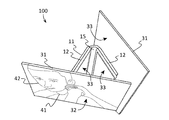
- FIG. 1 depicts a top perspective view of an example of a reconfigurable modular display system according to various embodiments described herein.
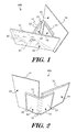
- FIG. 2 illustrates a rear perspective view of a further example of a reconfigurable modular display system according to various embodiments described herein.
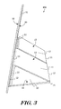
- FIG. 3 shows a side perspective view of another example of a reconfigurable modular display system according to various embodiments described herein.
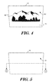
- FIG. 4 depicts a front perspective view of an example of a display apparatus according to various embodiments described herein.
- FIG. 5 illustrates a rear perspective view of an example of a display apparatus according to various embodiments described herein.
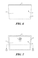
- FIG. 6 shows a front perspective view of an example of a reconfigurable modular apparatus according to various embodiments described herein.
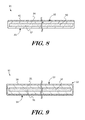
- FIG. 7 depicts a rear perspective view of an example of a reconfigurable modular apparatus according to various embodiments described herein.
- FIG. 8 illustrates a sectional, through line A-A shown in FIG. 5 , elevation view of an example of a display apparatus according to various embodiments described herein.
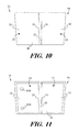
- FIG. 9 shows a sectional, through line B-B shown in FIG. 7 , elevation view of an example of a reconfigurable modular apparatus according to various embodiments described herein.
- FIG. 10 depicts a front perspective view of another example of a reconfigurable modular apparatus according to various embodiments described herein.
- FIG. 11 illustrates a rear perspective view of another example of a reconfigurable modular apparatus according to various embodiments described herein.
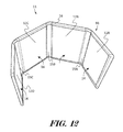
- FIG. 12 shows a rear perspective view of a further example of a reconfigurable modular apparatus according to various embodiments described herein.
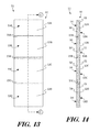
- FIG. 13 depicts a front elevation view of a further example of a reconfigurable modular apparatus according to various embodiments described herein.
- FIG. 14 illustrates a sectional, through line C-C shown in FIG. 13 , elevation view of a further example of a reconfigurable modular apparatus according to various embodiments described herein.
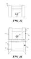
- FIG. 15 shows a rear perspective view of an example of a positioning apparatus according to various embodiments described herein.
- FIG. 16 depicts a rear perspective view of an example of a positioning apparatus and a reconfigurable modular apparatus according to various embodiments described herein.
- FIG. 17 illustrates a front perspective view of yet a further example of a reconfigurable modular display system according to various embodiments described herein.
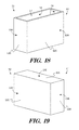
- FIG. 18 shows a top front perspective view of an example of a reconfigurable modular apparatus in a five-sided rectangular prism arrangement according to various embodiments described herein.
- FIG. 19 depicts a bottom rear perspective view of an example of a reconfigurable modular apparatus in a five-sided rectangular prism arrangement according to various embodiments described herein.
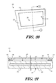
- FIG. 20 illustrates a front perspective view of an example of a reconfigurable modular apparatus comprising a mat according to various embodiments described herein.
- FIG. 21 shows a sectional, through line D-D shown in FIG. 20 , elevation view of an example of a reconfigurable modular apparatus comprising a mat according to various embodiments described herein.
- FIG. 22 depicts a sectional, through line E-E shown in FIG. 17 , elevation view of an example of a reconfigurable modular apparatus comprising a mat according to various embodiments described herein.
- the terms “upper”, “lower”, “left”, “right”, “rear”, “front”, “side”, “vertical”, “horizontal”, and derivatives thereof shall relate to the invention as oriented in FIG. 1 .
- the invention may assume various alternative orientations and step sequences, except where expressly specified to the contrary. Therefore, the specific devices and processes illustrated in the attached drawings, and described in the following specification, are simply exemplary embodiments of the inventive concepts defined in the appended claims. Hence, specific dimensions and other physical characteristics relating to the embodiments disclosed herein are not to be considered as limiting, unless the claims expressly state otherwise.
- first”, “second”, etc. are used herein to describe various elements, these elements should not be limited by these terms. These terms are only used to distinguish one element from another element.
- the first element may be designated as the second element, and the second element may be likewise designated as the first element without departing from the scope of the invention.
- the term “about” or “approximately” refers to a range of values within plus or minus 10% of the specified number. Additionally, as used in this application, the term “substantially” means that the actual value is within about 10% of the actual desired value, particularly within about 5% of the actual desired value and especially within about 1% of the actual desired value of any variable, element or limit set forth herein.
- FIGS. 1 3 , and 17 illustrate examples of a reconfigurable modular display system (“the system”) 100 according to various embodiments.
- the system 100 may comprise one or more display apparatuses 31 and one or more reconfigurable modular apparatuses 11 .
- a reconfigurable modular apparatus 11 may comprise one or more joining panels 12 , and each joining panel 12 may have a positioning surface 13 .
- a display apparatus 31 may comprise a display surface 32 , and the display surface 32 may be configured to be placed in contact with printed media 41 .
- each joining panel 12 and each display apparatus 31 may comprise a magnetic material 50 .
- a display apparatus 31 may be engaged to a positioning surface 13 of a joining panel 12 via magnetic attraction between the magnetic material 50 of the joining panel 12 and the magnetic material 50 of the display apparatus 31 .
- each display apparatus 31 may comprise a display surface 32 which may be suitable for receiving an image 42 .
- a display surface 32 may be generally flat or planar in shape, although a display surface 32 may be configured with any other shape and/or texture.
- the exemplary display apparatuses 31 are illustrated as a three-dimensional rectangle or thin rectangular prism; although a display apparatus 31 may be configured in any shape, such as three-dimensional square, circle, oval, or any other shape apparent to one having ordinary skill in the art.
- the display apparatus 31 may comprise a mounting surface 33 which may be disposed on the display apparatus 31 opposite to the display surface 32 .
- the surfaces 32 , 33 may be separated or optionally formed by a display body 34 .
- One or more magnetic materials 50 may be disposed in and/or or coupled to the display body 34 .
- a mounting surface 33 may form a portion of the display apparatus 31 which may contact portions of the positioning surface 13 of a joining panel 12 when the display apparatus 31 and joining panel 12 are engaged together.
- a mounting surface 33 may be generally flat or planar in shape, although a mounting surface 33 may be configured with any other shape and/or texture.
- an image 42 may be disposed on printed media 41 and the printed media 41 may be placed in contact with the display surface 32 of a display apparatus 31 by the print media 41 being coupled to the display surface 32 of a display apparatus 31 .
- An example of print media 41 may comprise an image 42 of a photograph printed on a substrate of photo paper.
- print media 41 may comprise an image 42 or indicia which may be applied to any substrate, such as paper, parchment, vinyl, and cardboard by a printer such as toner-based printers, liquid inkjet printers, solid ink printers, dye-sublimation printers, inkless printers, and the like.
- the print media 41 may be coupled to the display surface 32 of a display apparatus 31 with adhesives, heat bonding or any other coupling method to form a single unit.
- an image 42 may be applied directly to a display surface 32 such as by being painted, drawn, or otherwise applied by an animal, human, or machine.
- an image 42 may be painted, printed, drawn, burned, laid upon, or otherwise applied upon the display apparatus 31 in any way apparent to one having ordinary skill in the art. It should be noted that an image 42 may be any image, color, word, sentence, text, graphic, photograph, document, or any other graphic that may be disposed on the display surface 32 of the display apparatus 31 . In an alternative embodiment, the display surface 32 may be blank, so that a user may dispose his or her own image thereon, such as by painting, drawing, printing or the like. In further embodiments, an image 42 may be disposed on the display surface 32 (front) and/or mounting surface 33 (back) of a display apparatus 31 .
- the display apparatus 31 or one or more elements of the display apparatus 31 may be made from or comprise any durable, resilient material apparent to one having ordinary skill in the art, such as wood, plastic, cardboard, fiberglass, resin, metal, or any other material.
- a display apparatus 31 or one or more elements of the display apparatus 31 may comprise Bank paper, Banana paper, Bond paper, Book paper, Coated glossy paper, Coated matte surface paper, Construction paper, Sugar paper, Cotton paper, Fish paper, Inkjet paper, Kraft paper, Laid paper, Leather paper, Mummy paper, Oak Tag Paper, Sandpaper, Tyvek paper, Wallpaper, Washi, Waterproof paper, Wax paper, Wove paper, Xuan paper, and the like that may optionally be used to form all or portions of the display surface 32 , mounting surface 33 , or other portion of the display apparatus 31 .
- a display apparatus 31 or one or more elements of the display apparatus 31 may comprise a material suitable for printing and engraving including, but not limited to, vinyl or polyvinyl chloride (PVC) sheeting, such as gloss vinyl, matte vinyl, and scrim vinyl, polypropylene sheeting, magnetic sheeting, plastic sheeting, corrugated plastic, or any other type of material that may be printed on and engraved or cut with a cutting plotter that may optionally be used to form all or portions of the display surface 32 , mounting surface 33 , display body 34 or other portion of the display apparatus 31 .
- PVC polyvinyl chloride
- a display apparatus 31 may be any size, including any length, any width and any depth.
- a display apparatus 31 may be relatively small, such as about 1 inch by 1 inch by 0.025 inches, or may be relatively large, such as many inches or even feet in dimensions.
- a display apparatus 31 may have any depth, such as a shallow depth of around 0.025 inches or a very deep depth of around many inches or even feet.
- each reconfigurable modular apparatus 11 may comprise one or more joining panels 12 , and each joining panel 12 may comprise one or more positioning surfaces 13 and one or more bolster surfaces 14 .
- the surfaces 13 , 14 may be separated or optionally formed by a panel body 21 .
- One or more magnetic materials 50 may be disposed in and/or or coupled to the panel body 21 .
- a positioning surface 13 may be suitable for contacting a portion of a display apparatus 31 , such as a mounting surface 33 or display surface 32 .
- a positioning surface 13 may be generally flat or planar in shape, although a positioning surface 13 may be configured with any other shape and/or texture.
- the exemplary joining panels 12 are illustrated as a three-dimensional rectangle or thin rectangular prism; although a joining panel 12 may be configured in any shape, such as three-dimensional square, circle, oval, or any other shape apparent to one having ordinary skill in the art.
- a joining panel 12 may comprise a positioning surface 13 which may be disposed on the joining panel 12 opposite to the bolster surface 14 .
- a bolster surface 14 may form a portion of the joining panel 12 which may contact portions of other objects, such as walls and a surface of another joining panel 12 when two or more joining panels 12 are magnetically engaged together ( FIGS. 1, 3, and 17 ).
- a bolster surface 14 may be generally flat or planar in shape, although a bolster surface 14 may be configured with any other shape and/or texture.
- the two reconfigurable modular apparatus 11 may be secured together by the magnetic attraction between the contacting joining panels 12 .
- three, four, five, six, seven, or more reconfigurable modular apparatuses 11 may be magnetically adhered to each other.
- one or more positioning apparatuses 62 may be magnetically adhered to one or more joining panels 12 allowing one or more reconfigurable modular apparatuses 11 to be secured to a vertical surface such as a wall, door, or other structure.
- a joining panel 12 may be configured in any size, including any length, any width and any depth.
- a joining panel 12 may be relatively small, such as about 1 inch by 1 inch by 0.025 inches, or may be relatively large, such as many inches or even feet in dimension.
- a joining panel 12 may have any depth, such as a shallow depth of around 0.025 inches or a very deep depth of around many inches or even feet. All or portions of a joining panel 12 , such as a positioning surface 13 and bolster surface 14 , may be made from or comprise any material that a display apparatus 31 may be made from or comprise.
- the panel body 21 of a joining panel 12 may be substantially rigid and may be made from or comprise wood, cardboard, metal, plastic, or any other suitable substantially rigid material.
- the panel body 21 of a joining panel 12 may be flexible and may be made from or comprise flexible plastic, cardboard, silicone, fabric, or any other suitable flexible material.
- a reconfigurable modular apparatus 11 may comprise two joining panels 12 which may be pivotally coupled together with at least one hinge 15 and preferably two hinges 15 .
- two joining panels 12 may be coupled together with two hinges 15 which may be separated by a spine 22 .
- the spine 22 , hinges 15 , and joining panels 12 may be configured similar to a book binding.
- a spine 22 may be of any thickness or width and preferably comprise a substantially rigid material, although other materials may be used.
- a hinge 15 may enable portions of the two joining panels 12 to be moved towards and away from each other to allow the joining panels 12 to be positioned within different 3 D planes relative to each other and relative to surfaces upon which a reconfigurable modular display system 100 may be placed or attached to.
- a hinge 15 may comprise a butt hinge, piano hinge, barrel hinge, butt/Mortise hinge, case hinge, flag hinge, strap hinge, H hinge, HL hinge, piano hinge, butterfly hinge, flush hinge, barrel hinge, concealed hinge, continuous hinge, T-hinge, strap hinge, double-acting hinge, Soss hinge, counterflap hinge, flush hinge, coach hinge, rising butt hinge, double action spring hinge, tee hinge, friction hinge, security hinge, cranked hinge or stormproof hinge, lift-off hinge, self closing or self positioning hinge, flexible material hinge, or any other type or style of hinge that may be configured to pivotally secure two joining panels 12 together.
- a hinge 15 may comprise a movable fastener such as rings or hoops, carabineer type fasteners, snap hook type fasteners, hook and loop type fasteners, rivets, or any other suitable fastener which may be configured to pivotally secure two joining panels 12 together.
- two joining panels 12 may be generally non-movably or substantially rigidly coupled together. In further alternative embodiments, two joining panels 12 may be removably coupled together.
- a hinge 15 may comprise a so-called “living” hinge, which typically comprises a linear, relatively flexible area between two relatively more rigid components, such as a line of thin plastic or flexible metal between thicker or more rigid portions, as is well known in the art.
- a hinge 15 configured as a living hinge may be formed by one or more flexible coverings 16 which may be placed over one or more portions of the joining panels 12 , such as over, under, or forming the positioning surface 13 and/or bolster surface 14 , and the one or more flexible coverings 16 may function as a living hinge or flex joint type of hinge 15 , thereby allowing the two joining panels 12 to be flexibly and pivotally secured together.
- a flexible covering 16 may be made from any substantially flexible material(s) such as a fabric material.
- a reconfigurable modular apparatus 11 may comprise one, two, three, four, five, six, seven, or more, such as a plurality of joining panels 12 .
- a reconfigurable modular apparatus 11 may comprise two or more joining panels 12 , and each joining panel 12 may be pivotally coupled to at least one other joining panel 12 .
- a reconfigurable modular apparatus 11 may comprise two or more joining panels 12 , and each joining panel 12 may be rigidly coupled to at least one other joining panel 12 .
- a reconfigurable modular apparatus 11 may comprise a first joining panel 12 A having a first positioning surface 13 A and a second joining panel 12 B having a second positioning surface 13 B.
- the first joining panel 12 A may be pivotally coupled to the second joining panel 12 B with a hinge 15 .
- Each joining panel 12 A, 12 B may comprise a magnetic material 50 , such as a primary magnetic material 51 , which may enable each joining panel 12 A, 12 B, to magnetically engage a magnetic material 50 , such as a secondary magnetic material 52 , of one or more display apparatuses 31 and to magnetically engage a magnetic material 50 of another joining panel 12 .
- a reconfigurable modular apparatus 11 may comprise a first joining panel 12 A having a first positioning surface 13 A, a second joining panel 12 B having a second positioning surface 13 B, a third joining panel 12 C having a third positioning surface 13 C, and a fourth joining panel 12 D having a fourth positioning surface 13 D.
- Each joining panel 12 A, 12 B, 12 C, 12 D may comprise a magnetic material 50 , such as a primary magnetic material 51 , which may enable each joining panel 12 A, 12 B, 12 C, 12 D, to magnetically engage a magnetic material 50 , such as a secondary magnetic material 52 , of one or more display apparatuses 31 and to magnetically engage a magnetic material 50 of another joining panel 12 .
- first joining panel 12 A, second joining panel 12 B, third joining panel 12 C, and fourth joining panel 12 D may be pivotally coupled together in a linear arrangement 91 .
- first joining panel 12 A may be coupled to the second joining panel 12 B with a first hinge 15 A
- third joining panel 12 C may be coupled to the second joining panel 12 B opposite to the first joining panel 12 A with a second hinge 15 B
- fourth joining panel 12 D may be coupled to the third joining panel 12 C opposite to the second joining panel 12 B with a third hinge 15 C.
- each display apparatus 31 may comprise a magnetic material 50
- at least one joining panel 12 of a reconfigurable modular apparatus 11 may comprise a magnetic material 50
- the attraction of the magnetic material 50 of a display apparatus 31 and the magnetic material 50 of a joining panel 12 may secure or engage the display apparatus 31 and joining panel 12 together when they are placed in contact with each other.
- the attraction of the magnetic material 50 of one joining panel 12 and the magnetic material 50 of another joining panel 12 may secure or engage the two joining panels 12 together when they are placed in contact with each other.
- the magnetic material 50 of a joining panel 12 may be disposed across an area of the joining panel 12 corresponding to the area of the positioning surface 13 , or the magnetic material 50 may be disposed across or in one or more portions of the joining panel 12 .
- the magnetic material 50 of a display apparatus 31 may be disposed across an area of the display apparatus 31 corresponding to the area of the display surface 32 , or the magnetic material 50 may be disposed across or in one or more portions of the display surface 32 .
- Magnetic material 50 may be substantially rigid or flexible and may be positioned on an exterior surface, but is preferably disposed within an element of the system 100 or covered with a non-metallic material.
- a magnetic material 50 may include or comprise ferrite, manganese-zinc ferrite, nickel-zinc ferrite, strontium ferrite, cobalt ferrite, barium ferrite, magnetic alloys such as alnico, comol, Hypernom® magnetic alloy, manganese-zinc ferrite, iron-silicon magnet alloys, nickel-zinc ferrite, ferritic stainless steel alloys, strontium ferrite, barium ferrite, alnico, iron-silicon magnet alloy, Chromindur® (Chromium-Cobalt-Iron) alloys, Silmanal (Silver-Manganese-Aluminium) alloys, Platinax II (platinum-cobalt) alloy, Bismanol (manganese bismuthide) alloy, cobalt-platinum alloys, chromium-manganese antimonide alloy, vectolite (cobalt ferrite), magnadur (sintered barium ferrite),
- a magnetic material 50 may be a primary magnetic material 51 or a secondary magnetic material 52 .
- a primary magnetic material 51 may generally comprise a magnetic material capable of generating a magnetic field.
- Example primary magnetic materials 51 include ferrite, manganese-zinc ferrite, nickel-zinc ferrite, strontium ferrite, cobalt ferrite, barium ferrite, alnico, iron-silicon magnet alloy, Chromium-Cobalt-Iron alloy, iron-cobalt alloy, Silver-Manganese-Aluminium alloy, manganese bismuthide alloy, platinum-cobalt alloy, chromium-manganese antimonide alloy, sintered barium ferrite, oxide-coated iron-cobalt particles, nickel-iron alloy, samarium-cobalt alloy, cesium-cobalt alloy, and neodymium-iron-boron alloy.
- a secondary magnetic material 52 may generally comprise a magnetic material that is substantially unable to generate a magnetic field, but which is attracted to magnetic fields.
- secondary magnetic materials include ferritic stainless steel, iron, other ferromagnetic metals such as nickel, cobalt, gadolinium, dysprosium, and alloys such as steel that contain ferromagnetic metals.
- each joining panel 12 of the system 100 may comprise a primary magnetic material 51 and each display apparatus 31 of the system 100 may comprise a secondary magnetic material 52 .
- a joining panel 12 may comprise a primary magnetic material 51 and/or a secondary magnetic material 52
- a display apparatus 31 may comprise a primary magnetic material 51 and/or a secondary magnetic material 52 .
- FIG. 3 depicts a top perspective view of the back of an example of a reconfigurable modular display system 100 according to various embodiments described herein.
- the system 100 comprises two display apparatuses 31 which are magnetically adhered to a joining panel 12 of a reconfigurable modular apparatus 11 allowing each display apparatus 31 to be positioned in a different 3D plane relative to each other by pivoting a hinge 15 to a desired orientation.
- the mounting surface 33 of each display apparatus 31 is contacting and magnetically adhered to the positioning surface 13 of a joining panel 12 .
- the mounting surface 33 and/or display surface 32 of a display apparatus 31 may contact and be magnetically adhered to the positioning surface 13 and/or bolster surface 14 of a joining panel 12 .
- the system 100 may comprise one or more panel supports 61 as shown in FIGS. 7, 15, and 16 .
- a panel support 61 may be coupled to an element of the system 100 and used to suspend or support one or more other elements of the system 100 above another object or surface.
- a panel support 61 may be coupled to a joining panel 12 , such as to the bolster surface 14 , of a reconfigurable modular apparatus 11 as shown in FIG. 7 .
- the system 100 may comprise a positioning apparatus 62 to which a panel support 61 may be coupled.
- a positioning apparatus 62 may comprise a substantially rigid material and a magnetic material 50 , and the magnetic material 50 may enable a reconfigurable modular apparatus 11 and/or a display apparatus 31 to be coupled to the positioning apparatus 62 .
- a panel support 61 may be any type of hanging means which may be used to support the weight of the system 100 above an object or to a surface such as a wall.
- a panel support 61 may comprise a hinged ring type hanger as shown in FIGS. 7, 15, and 16 , that is configured to be secured to fasteners on vertical surfaces such as hook, nails, threaded fasteners, and the like.
- a panel support 61 may include saw tooth fasteners, picture hanging wire, a depression, a cutout or aperture, hook and loop type fasteners, or any other hanging means that is suitable for securing an element of the system 100 to a generally vertical surface including walls, doors, cabinets, and other structures.
- a panel support 61 may comprise a fastener aperture 61 A as shown in FIG. 11 which may comprise a hole or depression which is configured to be secured to fasteners on vertical surfaces such as hooks, nails, threaded fasteners, and the like allowing a reconfigurable modular apparatus 11 to be secured directly to a wall or other vertical surface.
- one or more fastener apertures 61 A may be positioned anywhere on a positioning apparatus 11 such as on one or more joining panels 12 , or on any other element or apparatus of a reconfigurable modular display system 100 .
- a positioning apparatus 62 may comprise a magnetic material 50 that allows it to be magnetically adhered to reconfigurable modular apparatuses 11 and/or to display apparatuses 31 .
- the magnetic material 50 may be disposed across the entire area of a positioning apparatus 62 , or the magnetic material 50 may be disposed across one or more portions of the positioning apparatus 62 .
- the magnetic material 50 may be substantially rigid or flexible and may be positioned on an exterior surface, but is preferably disposed within the positioning apparatus 62 or covered with a non-metallic material.
- a positioning apparatus 62 may be permanently joined to a joining panel 12 of a reconfigurable modular apparatus 11 with heat bonding, chemical bonding, adhesives, clasp type fasteners, rivet type fasteners, threaded fasteners, other types of fasteners, by being integrally molded or formed together, or any other suitable substantially permanent joining method.
- the positioning apparatus 62 is illustrated as a three-dimensional rectangle, although a positioning apparatus 62 may be any shape, such as three-dimensional square, circle, oval, or any other shape apparent to one having ordinary skill in the art.
- the positioning apparatus 62 may be made from any durable, resilient material apparent to one having ordinary skill in the art, such as wood, plastic, cardboard, fiberglass, resin, metal, or any other material.
- FIG. 3 a perspective view of the side of an example of a reconfigurable modular display system 100 comprising a display apparatus 31 and two reconfigurable modular apparatuses 11 according to various embodiments described herein is shown.
- one large display apparatus 31 is magnetically adhered to and supported in a generally upright position by two reconfigurable modular apparatuses 11 each comprising four joining panels 12 .
- Each reconfigurable modular apparatus 11 has two joining panels 12 that are magnetically adhered to and joined together allowing the reconfigurable modular apparatuses 11 to assume a generally triangular conformation.
- one or more joining panels 12 from one reconfigurable modular apparatus 11 may be magnetically adhered to and joined to one or more joining panels 12 from one or more different reconfigurable modular apparatuses 11 allowing one or more display apparatuses 31 to be magnetically adhered to and joined to one or more joining panels 12 and thereby positioned in the same 3 D plane or different 3 D planes relative to each other.
- a reconfigurable modular apparatus 11 may be configured in a five-sided rectangular prism arrangement 92 suitable for acting as a container for one or more other elements of the system 100 .
- a reconfigurable modular apparatus 11 may comprise a first joining panel 12 A having a first positioning surface 13 A, a second joining panel 12 B having a second positioning surface 13 B, a third joining panel 12 C having a third positioning surface 13 C, a fourth joining panel 12 D having a fourth positioning surface 13 D, and a fifth joining panel 12 E having a fifth positioning surface 13 E, and the first joining panel 12 A, second joining panel 12 B, third joining panel 12 C, fourth joining panel 12 D, and fifth joining panel 12 E.
- the joining panels 12 A, 12 B, 12 C, 12 D, 12 E may each be configured with four rectangular side walls and joined to each other at approximately right angles or generally perpendicular to each other in a five-sided rectangular prism arrangement 92 .
- at least one joining panel 12 A, 12 B, 12 C, 12 D, 12 E may comprise a magnetic material 50 .
- the reconfigurable modular apparatus 11 configured in a five-sided rectangular prism arrangement 92 may comprise a receiving cavity 17 formed by the joining panels 12 A, 12 B, 12 C, 12 D, 12 E, which may be shaped to receive all or portions of at least one display apparatus 31 , at least one positioning apparatus 62 , and/or at least one other reconfigurable modular apparatus 11 .
- a receiving cavity 17 may be configured in any size and shape.
- the system 100 may comprise a mat 18 which may be coupled, optionally removably coupled such as magnetically coupled, to an element of the system 100 .
- a joining panel 12 may comprise a mat 18 which may be coupled to the positioning surface 13 .
- a mat 18 may be configured generally as a picture framing mat preferably made of a planar material having a central opening 20 .
- the perimeter of the mat 18 may be coupled to the positioning surface 13 so that a mat cavity 19 may be formed between portions of the mat 18 not coupled to the positioning surface 13 and the first positioning surface 13 .
- a mat cavity 19 may be shaped to receive and/or frictionally retain a unit of printed media 41 , such as a printed photograph, a document, or a painting so that portions of the image 42 on the printed media 41 may be viewed through the central opening 20 .
- a mat cavity 19 may be shaped to receive and/or frictionally retain a display apparatus 31 so that portions of the image 42 on the display apparatus 31 may be viewed through the central opening 20 .
- a mat 18 may comprise a magnetic material 50 which may enable the mat 18 to be magnetically coupled to a display apparatus 31 so that printed media 41 placed between the mat 18 and the display surface 32 may be maintained in contact with the display surface 32 by the magnetic engagement between the mat 18 and the display apparatus 31 .
- a mat 18 may comprise a magnetic material 50 which may enable the mat 18 to be magnetically coupled to a joining panel 12 of a reconfigurable modular apparatus 11 so that printed media 41 placed between the mat 18 and the joining panel 12 may be maintained in contact with the joining panel 12 by the magnetic engagement between the mat 18 and the joining panel 12 .
- printed media may be placed in contact with a display surface 32 by placing the print media 41 between a mat 18 and the display surface 32 of a display apparatus 31 .
- the elements that comprise the system 100 such as the reconfigurable modular apparatus 11 , display apparatus 31 , optional mat 18 , optional positioning apparatus 62 , and/or any other element discussed herein may be made from durable materials such as aluminum, steel, other metals and metal alloys, wood, hard rubbers, hard plastics, fiber reinforced plastics, carbon fiber, fiber glass, resins, polymers or any other suitable materials including combinations of materials. Additionally, one or more elements may be made from or comprise durable and slightly flexible materials such as soft plastics, silicone, soft rubbers, or any other suitable materials including combinations of materials.
- one or more of the elements that comprise the system 100 may be coupled or connected together with heat bonding, chemical bonding, adhesives, clasp type fasteners, clip type fasteners, rivet type fasteners, threaded type fasteners, other types of fasteners, or any other suitable joining method.
- one or more of the elements that comprise the system 100 may be coupled or removably connected by being press fit or snap fit together, by one or more fasteners such as hook and loop type or Velcro® fasteners, magnetic type fasteners, threaded type fasteners, sealable tongue and groove fasteners, snap fasteners, clip type fasteners, clasp type fasteners, ratchet type fasteners, a push-to-lock type connection method, a turn-to-lock type connection method, a slide-to-lock type connection method or any other suitable temporary connection method as one reasonably skilled in the art could envision to serve the same function.
- one or more of the elements that comprise the system 100 may be coupled by being one of connected to and integrally formed with another element of the system 100 .
Landscapes
- Devices For Indicating Variable Information By Combining Individual Elements (AREA)
Abstract
A reconfigurable modular display system may include one or more display apparatuses and one or more reconfigurable modular apparatuses. A reconfigurable modular apparatus may comprise one or more joining panels, and each joining panel may have a positioning surface. A display apparatus may comprise a display surface, and the display surface may be configured to be placed in contact with printed media. Preferably, each joining panel and each display apparatus may comprise a magnetic material. The display apparatus and joining panel may each comprise a magnetic material. A display apparatus may be engaged to a positioning surface of a joining panel via magnetic attraction between the magnetic material of the joining panel and the magnetic material of the display apparatus.
Description
- This application claims priority to and the benefit of the filing date of U.S. Provisional Application No. 62/406,528, filed on Oct. 11, 2016, entitled “RECONFIGURABLE MODULAR DISPLAY APPARATUSES AND SYSTEMS”, which is hereby incorporated by reference in its entirety.
- The present invention relates to the field of picture and image display apparatuses and systems. More specifically, the invention relates to modular and reconfigurable apparatuses and systems for displaying pictures and other printed media.
- Devices for displaying images and documents are known in the art and are often referred to as picture frames and document displays. One type of image and document display device comprises a rectangular frame with an open center, often with a transparent plate of material positioned in the open center, with a back cover configured to secure a printed image within the device. However, these devices are only able to accommodate printed images that may fit between the frame and the back cover. Since printed images come in a variety of sizes, many different devices are required to display images of different sizes. Another drawback to these picture frame devices is that they require images contained within them to be displayed in a single plane, thereby severely limiting the display of images to a two dimensional organization and precluding different three dimensional image displays by a single device.
- Another type of image and document display device comprises one or more planar panels that have a magnetic material disposed through portions of the panels. The panels may be hung on a wall or on a stand with each panel aligned in the same plane as the other panels. One or more printed images, documents, or other objects may be magnetically attached to the panels in different orientations relative to each other and the panels. However, due to the planar two dimensional arrangement of the panels, images magnetically attached to them are also required to be displayed in a single plane, thereby severely limiting the display of images to a two dimensional organization and precluding different three dimensional image displays by a single device even though it may comprise more than one panel.
- Further types of image and document display devices attempt to allow for three dimensional displays by configuring the devices with a stand that protrudes from the rear of the back cover of each display device. The stand may be attached or folded out from the device to allow the device to be free standing on a horizontal surface and then the stand may be detached or folded back against the device to allow the device to be hung on a vertical surface. However, these stands are only able to support one device so that multiple stands are required to individually support multiple devices. Furthermore, these stands are unable to attach to other stands also resulting in limited three dimensional display options
- One drawback common to all of these types of image and document display devices, is a universal inability to display multiple images and documents in different three dimensional configurations on or by a single device. Since these devices do not allow for different three dimensional displays of multiple images, many separate devices are required to provide different three dimensional display options. Since small spaces are unable to accommodate multiple devices, the image and display options for these spaces are severely limited.
- Therefore, a need exists for novel apparatuses and systems for displaying images and documents. There also exists a need for novel apparatuses and systems for displaying images and documents of a plurality of sizes and shapes. There is a further need for novel apparatuses and systems for displaying images and documents that are able to display images and documents in different three dimensional arrangements. Finally, there exists a need for novel apparatuses and systems for displaying images and documents that are able to simultaneously display multiple images and documents of various sizes and shapes in different three dimensional configurations on or by a single device.
- A reconfigurable modular display system is provided. In some embodiments, the system may include one or more display apparatuses and one or more reconfigurable modular apparatuses. A display apparatus may comprise a magnetic material and a display surface configured to be placed in contact with printed media. A reconfigurable modular apparatus may comprise a first joining panel having a first positioning surface and a magnetic material. The magnetic material of the joining panel may be configured to engage the display apparatus to the first positioning surface via magnetic attraction between the magnetic material of the first joining panel and the magnetic material of the display apparatus.
- In further embodiments, the system may have a display apparatus and a reconfigurable modular apparatus. The display apparatus may include a magnetic material and a display surface configured to be placed in contact with printed media. The reconfigurable modular apparatus may include a first joining panel having both a first positioning surface and a magnetic material. The reconfigurable modular apparatus may also include a second joining panel having both a second positioning surface and a magnetic material, and the first joining panel may be pivotally coupled to the second joining panel with a first hinge. The reconfigurable modular apparatus may be configured to engage the display apparatus to at least one positioning surface via magnetic attraction between the magnetic material of at least one joining panel and the magnetic material of the display apparatus.
- Another object of the present invention is to provide novel reconfigurable modular display apparatuses and systems that are able to display images and documents of a plurality of sizes and shapes.
- An additional object of the present invention is to provide novel reconfigurable modular display apparatuses and systems that are able to display images and documents in different three dimensional arrangements.
- It is a further object of the present invention to provide novel reconfigurable modular display apparatuses and systems that are able to simultaneously display multiple images and documents of various sizes and shapes in different three dimensional configurations on or by a single device.
- Some embodiments of the present invention are illustrated as an example and are not limited by the figures of the accompanying drawings, in which like references may indicate similar elements and in which:
-
FIG. 1 depicts a top perspective view of an example of a reconfigurable modular display system according to various embodiments described herein. -
FIG. 2 illustrates a rear perspective view of a further example of a reconfigurable modular display system according to various embodiments described herein. -
FIG. 3 shows a side perspective view of another example of a reconfigurable modular display system according to various embodiments described herein. -
FIG. 4 depicts a front perspective view of an example of a display apparatus according to various embodiments described herein. -
FIG. 5 illustrates a rear perspective view of an example of a display apparatus according to various embodiments described herein. -
FIG. 6 shows a front perspective view of an example of a reconfigurable modular apparatus according to various embodiments described herein. -
FIG. 7 depicts a rear perspective view of an example of a reconfigurable modular apparatus according to various embodiments described herein. -
FIG. 8 illustrates a sectional, through line A-A shown inFIG. 5 , elevation view of an example of a display apparatus according to various embodiments described herein. -
FIG. 9 shows a sectional, through line B-B shown inFIG. 7 , elevation view of an example of a reconfigurable modular apparatus according to various embodiments described herein. -
FIG. 10 depicts a front perspective view of another example of a reconfigurable modular apparatus according to various embodiments described herein. -
FIG. 11 illustrates a rear perspective view of another example of a reconfigurable modular apparatus according to various embodiments described herein. -
FIG. 12 shows a rear perspective view of a further example of a reconfigurable modular apparatus according to various embodiments described herein. -
FIG. 13 depicts a front elevation view of a further example of a reconfigurable modular apparatus according to various embodiments described herein. -
FIG. 14 illustrates a sectional, through line C-C shown inFIG. 13 , elevation view of a further example of a reconfigurable modular apparatus according to various embodiments described herein. -
FIG. 15 shows a rear perspective view of an example of a positioning apparatus according to various embodiments described herein. -
FIG. 16 depicts a rear perspective view of an example of a positioning apparatus and a reconfigurable modular apparatus according to various embodiments described herein. -
FIG. 17 illustrates a front perspective view of yet a further example of a reconfigurable modular display system according to various embodiments described herein. -
FIG. 18 shows a top front perspective view of an example of a reconfigurable modular apparatus in a five-sided rectangular prism arrangement according to various embodiments described herein. -
FIG. 19 depicts a bottom rear perspective view of an example of a reconfigurable modular apparatus in a five-sided rectangular prism arrangement according to various embodiments described herein. -
FIG. 20 illustrates a front perspective view of an example of a reconfigurable modular apparatus comprising a mat according to various embodiments described herein. -
FIG. 21 shows a sectional, through line D-D shown inFIG. 20 , elevation view of an example of a reconfigurable modular apparatus comprising a mat according to various embodiments described herein. -
FIG. 22 depicts a sectional, through line E-E shown inFIG. 17 , elevation view of an example of a reconfigurable modular apparatus comprising a mat according to various embodiments described herein. - The terminology used herein is for the purpose of describing particular embodiments only and is not intended to be limiting of the invention. As used herein, the term “and/or” includes any and all combinations of one or more of the associated listed items. As used herein, the singular forms “a,” “an,” and “the” are intended to include the plural forms as well as the singular forms, unless the context clearly indicates otherwise. It will be further understood that the terms “comprises” and/or “comprising,” when used in this specification, specify the presence of stated features, steps, operations, elements, and/or components, but do not preclude the presence or addition of one or more other features, steps, operations, elements, components, and/or groups thereof.
- Unless otherwise defined, all terms (including technical and scientific terms) used herein have the same meaning as commonly understood by one having ordinary skill in the art to which this invention belongs. It will be further understood that terms, such as those defined in commonly used dictionaries, should be interpreted as having a meaning that is consistent with their meaning in the context of the relevant art and the present disclosure and will not be interpreted in an idealized or overly formal sense unless expressly so defined herein.
- In describing the invention, it will be understood that a number of techniques and steps are disclosed. Each of these has individual benefit and each can also be used in conjunction with one or more, or in some cases all, of the other disclosed techniques. Accordingly, for the sake of clarity, this description will refrain from repeating every possible combination of the individual steps in an unnecessary fashion. Nevertheless, the specification and claims should be read with the understanding that such combinations are entirely within the scope of the invention and the claims.
- For purposes of description herein, the terms “upper”, “lower”, “left”, “right”, “rear”, “front”, “side”, “vertical”, “horizontal”, and derivatives thereof shall relate to the invention as oriented in
FIG. 1 . However, one will understand that the invention may assume various alternative orientations and step sequences, except where expressly specified to the contrary. Therefore, the specific devices and processes illustrated in the attached drawings, and described in the following specification, are simply exemplary embodiments of the inventive concepts defined in the appended claims. Hence, specific dimensions and other physical characteristics relating to the embodiments disclosed herein are not to be considered as limiting, unless the claims expressly state otherwise. - Although the terms “first”, “second”, etc. are used herein to describe various elements, these elements should not be limited by these terms. These terms are only used to distinguish one element from another element. For example, the first element may be designated as the second element, and the second element may be likewise designated as the first element without departing from the scope of the invention.
- As used in this application, the term “about” or “approximately” refers to a range of values within plus or minus 10% of the specified number. Additionally, as used in this application, the term “substantially” means that the actual value is within about 10% of the actual desired value, particularly within about 5% of the actual desired value and especially within about 1% of the actual desired value of any variable, element or limit set forth herein.
- New picture and image display apparatuses and systems are discussed herein. In the following description, for purposes of explanation, numerous specific details are set forth in order to provide a thorough understanding of the present invention. It will be evident, however, to one skilled in the art that the present invention may be practiced without these specific details.
- The present disclosure is to be considered as an exemplification of the invention, and is not intended to limit the invention to the specific embodiments illustrated by the figures or description below.
- The present invention will now be described by example and through referencing the appended figures representing preferred and alternative embodiments.
FIGS. 1 3, and 17 illustrate examples of a reconfigurable modular display system (“the system”) 100 according to various embodiments. In some embodiments, thesystem 100 may comprise one ormore display apparatuses 31 and one or more reconfigurablemodular apparatuses 11. A reconfigurablemodular apparatus 11 may comprise one or more joiningpanels 12, and each joiningpanel 12 may have apositioning surface 13. Adisplay apparatus 31 may comprise adisplay surface 32, and thedisplay surface 32 may be configured to be placed in contact with printedmedia 41. Preferably, each joiningpanel 12 and eachdisplay apparatus 31 may comprise amagnetic material 50. Adisplay apparatus 31 may be engaged to apositioning surface 13 of a joiningpanel 12 via magnetic attraction between themagnetic material 50 of the joiningpanel 12 and themagnetic material 50 of thedisplay apparatus 31. - As perhaps best shown in
FIGS. 1 5, and 8, in some embodiments, eachdisplay apparatus 31 may comprise adisplay surface 32 which may be suitable for receiving animage 42. Preferably, adisplay surface 32 may be generally flat or planar in shape, although adisplay surface 32 may be configured with any other shape and/or texture. Theexemplary display apparatuses 31 are illustrated as a three-dimensional rectangle or thin rectangular prism; although adisplay apparatus 31 may be configured in any shape, such as three-dimensional square, circle, oval, or any other shape apparent to one having ordinary skill in the art. Preferably, thedisplay apparatus 31 may comprise a mountingsurface 33 which may be disposed on thedisplay apparatus 31 opposite to thedisplay surface 32. Thesurfaces display body 34. One or moremagnetic materials 50 may be disposed in and/or or coupled to thedisplay body 34. A mountingsurface 33 may form a portion of thedisplay apparatus 31 which may contact portions of thepositioning surface 13 of a joiningpanel 12 when thedisplay apparatus 31 and joiningpanel 12 are engaged together. Preferably, a mountingsurface 33 may be generally flat or planar in shape, although a mountingsurface 33 may be configured with any other shape and/or texture. - In some embodiments, an
image 42 may be disposed on printedmedia 41 and the printedmedia 41 may be placed in contact with thedisplay surface 32 of adisplay apparatus 31 by theprint media 41 being coupled to thedisplay surface 32 of adisplay apparatus 31. An example ofprint media 41 may comprise animage 42 of a photograph printed on a substrate of photo paper. However,print media 41 may comprise animage 42 or indicia which may be applied to any substrate, such as paper, parchment, vinyl, and cardboard by a printer such as toner-based printers, liquid inkjet printers, solid ink printers, dye-sublimation printers, inkless printers, and the like. Preferably, theprint media 41 may be coupled to thedisplay surface 32 of adisplay apparatus 31 with adhesives, heat bonding or any other coupling method to form a single unit. In other embodiments, animage 42 may be applied directly to adisplay surface 32 such as by being painted, drawn, or otherwise applied by an animal, human, or machine. - In alternative embodiments, an
image 42 may be painted, printed, drawn, burned, laid upon, or otherwise applied upon thedisplay apparatus 31 in any way apparent to one having ordinary skill in the art. It should be noted that animage 42 may be any image, color, word, sentence, text, graphic, photograph, document, or any other graphic that may be disposed on thedisplay surface 32 of thedisplay apparatus 31. In an alternative embodiment, thedisplay surface 32 may be blank, so that a user may dispose his or her own image thereon, such as by painting, drawing, printing or the like. In further embodiments, animage 42 may be disposed on the display surface 32 (front) and/or mounting surface 33 (back) of adisplay apparatus 31. - The
display apparatus 31 or one or more elements of thedisplay apparatus 31, such as thedisplay surface 32, mountingsurface 33, and/ordisplay body 34 may be made from or comprise any durable, resilient material apparent to one having ordinary skill in the art, such as wood, plastic, cardboard, fiberglass, resin, metal, or any other material. In some embodiments, adisplay apparatus 31 or one or more elements of thedisplay apparatus 31 may comprise Bank paper, Banana paper, Bond paper, Book paper, Coated glossy paper, Coated matte surface paper, Construction paper, Sugar paper, Cotton paper, Fish paper, Inkjet paper, Kraft paper, Laid paper, Leather paper, Mummy paper, Oak Tag Paper, Sandpaper, Tyvek paper, Wallpaper, Washi, Waterproof paper, Wax paper, Wove paper, Xuan paper, and the like that may optionally be used to form all or portions of thedisplay surface 32, mountingsurface 33, or other portion of thedisplay apparatus 31. In other embodiments, adisplay apparatus 31 or one or more elements of thedisplay apparatus 31 may comprise a material suitable for printing and engraving including, but not limited to, vinyl or polyvinyl chloride (PVC) sheeting, such as gloss vinyl, matte vinyl, and scrim vinyl, polypropylene sheeting, magnetic sheeting, plastic sheeting, corrugated plastic, or any other type of material that may be printed on and engraved or cut with a cutting plotter that may optionally be used to form all or portions of thedisplay surface 32, mountingsurface 33,display body 34 or other portion of thedisplay apparatus 31. - A
display apparatus 31 may be any size, including any length, any width and any depth. For example, adisplay apparatus 31 may be relatively small, such as about 1 inch by 1 inch by 0.025 inches, or may be relatively large, such as many inches or even feet in dimensions. Moreover, adisplay apparatus 31 may have any depth, such as a shallow depth of around 0.025 inches or a very deep depth of around many inches or even feet. - As perhaps best shown in
FIGS. 1 5, and 8, in some embodiments, each reconfigurablemodular apparatus 11 may comprise one or more joiningpanels 12, and each joiningpanel 12 may comprise one or more positioning surfaces 13 and one or more bolster surfaces 14. Thesurfaces panel body 21. One or moremagnetic materials 50 may be disposed in and/or or coupled to thepanel body 21. Apositioning surface 13 may be suitable for contacting a portion of adisplay apparatus 31, such as a mountingsurface 33 ordisplay surface 32. Preferably, apositioning surface 13 may be generally flat or planar in shape, although apositioning surface 13 may be configured with any other shape and/or texture. The exemplary joiningpanels 12 are illustrated as a three-dimensional rectangle or thin rectangular prism; although a joiningpanel 12 may be configured in any shape, such as three-dimensional square, circle, oval, or any other shape apparent to one having ordinary skill in the art. Preferably, a joiningpanel 12 may comprise apositioning surface 13 which may be disposed on the joiningpanel 12 opposite to the bolstersurface 14. A bolstersurface 14 may form a portion of the joiningpanel 12 which may contact portions of other objects, such as walls and a surface of another joiningpanel 12 when two or more joiningpanels 12 are magnetically engaged together (FIGS. 1, 3, and 17 ). Preferably, a bolstersurface 14 may be generally flat or planar in shape, although a bolstersurface 14 may be configured with any other shape and/or texture. - In some embodiments, by placing one or more joining
panels 12 from a reconfigurablemodular apparatus 11 in contact with one or more joiningpanels 12 from the other reconfigurablemodular apparatus 11, the two reconfigurablemodular apparatus 11 may be secured together by the magnetic attraction between the contacting joiningpanels 12. In other embodiments, three, four, five, six, seven, or more reconfigurablemodular apparatuses 11 may be magnetically adhered to each other. Additionally, one ormore positioning apparatuses 62 may be magnetically adhered to one or more joiningpanels 12 allowing one or more reconfigurablemodular apparatuses 11 to be secured to a vertical surface such as a wall, door, or other structure. - A joining
panel 12 may be configured in any size, including any length, any width and any depth. For example, a joiningpanel 12 may be relatively small, such as about 1 inch by 1 inch by 0.025 inches, or may be relatively large, such as many inches or even feet in dimension. Moreover, a joiningpanel 12 may have any depth, such as a shallow depth of around 0.025 inches or a very deep depth of around many inches or even feet. All or portions of a joiningpanel 12, such as apositioning surface 13 and bolstersurface 14, may be made from or comprise any material that adisplay apparatus 31 may be made from or comprise. In preferred embodiments, thepanel body 21 of a joiningpanel 12 may be substantially rigid and may be made from or comprise wood, cardboard, metal, plastic, or any other suitable substantially rigid material. In other embodiments, thepanel body 21 of a joiningpanel 12 may be flexible and may be made from or comprise flexible plastic, cardboard, silicone, fabric, or any other suitable flexible material. - In some embodiments and as shown in
FIGS. 1 3, 10-14, 16, and 17, a reconfigurablemodular apparatus 11 may comprise two joiningpanels 12 which may be pivotally coupled together with at least onehinge 15 and preferably two hinges 15. In some embodiments, and as shown inFIGS. 10 and 11 , two joiningpanels 12 may be coupled together with twohinges 15 which may be separated by aspine 22. In this manner, thespine 22, hinges 15, and joiningpanels 12 may be configured similar to a book binding. Aspine 22 may be of any thickness or width and preferably comprise a substantially rigid material, although other materials may be used. - A
hinge 15 may enable portions of the two joiningpanels 12 to be moved towards and away from each other to allow the joiningpanels 12 to be positioned within different 3D planes relative to each other and relative to surfaces upon which a reconfigurablemodular display system 100 may be placed or attached to. In some embodiments, ahinge 15 may comprise a butt hinge, piano hinge, barrel hinge, butt/Mortise hinge, case hinge, flag hinge, strap hinge, H hinge, HL hinge, piano hinge, butterfly hinge, flush hinge, barrel hinge, concealed hinge, continuous hinge, T-hinge, strap hinge, double-acting hinge, Soss hinge, counterflap hinge, flush hinge, coach hinge, rising butt hinge, double action spring hinge, tee hinge, friction hinge, security hinge, cranked hinge or stormproof hinge, lift-off hinge, self closing or self positioning hinge, flexible material hinge, or any other type or style of hinge that may be configured to pivotally secure two joiningpanels 12 together. - In other embodiments, a
hinge 15 may comprise a movable fastener such as rings or hoops, carabineer type fasteners, snap hook type fasteners, hook and loop type fasteners, rivets, or any other suitable fastener which may be configured to pivotally secure two joiningpanels 12 together. In alternative embodiments, two joiningpanels 12 may be generally non-movably or substantially rigidly coupled together. In further alternative embodiments, two joiningpanels 12 may be removably coupled together. - In preferred embodiments, a
hinge 15 may comprise a so-called “living” hinge, which typically comprises a linear, relatively flexible area between two relatively more rigid components, such as a line of thin plastic or flexible metal between thicker or more rigid portions, as is well known in the art. In further preferred embodiments, ahinge 15 configured as a living hinge may be formed by one or moreflexible coverings 16 which may be placed over one or more portions of the joiningpanels 12, such as over, under, or forming thepositioning surface 13 and/or bolstersurface 14, and the one or moreflexible coverings 16 may function as a living hinge or flex joint type ofhinge 15, thereby allowing the two joiningpanels 12 to be flexibly and pivotally secured together. Aflexible covering 16 may be made from any substantially flexible material(s) such as a fabric material. - A reconfigurable
modular apparatus 11 may comprise one, two, three, four, five, six, seven, or more, such as a plurality of joiningpanels 12. In some embodiments, a reconfigurablemodular apparatus 11 may comprise two or more joiningpanels 12, and each joiningpanel 12 may be pivotally coupled to at least one other joiningpanel 12. In further embodiments, a reconfigurablemodular apparatus 11 may comprise two or more joiningpanels 12, and each joiningpanel 12 may be rigidly coupled to at least one other joiningpanel 12. - Referring to the examples of
FIGS. 2, 10, 11, 16, and 17 , in some embodiments, a reconfigurablemodular apparatus 11 may comprise a first joiningpanel 12A having afirst positioning surface 13A and a second joiningpanel 12B having asecond positioning surface 13B. The first joiningpanel 12A may be pivotally coupled to the second joiningpanel 12B with ahinge 15. Each joiningpanel magnetic material 50, such as a primarymagnetic material 51, which may enable each joiningpanel magnetic material 50, such as a secondarymagnetic material 52, of one ormore display apparatuses 31 and to magnetically engage amagnetic material 50 of another joiningpanel 12. - Referring to the examples of
FIGS. 12-14 , in some embodiments, a reconfigurablemodular apparatus 11 may comprise a first joiningpanel 12A having afirst positioning surface 13A, a second joiningpanel 12B having asecond positioning surface 13B, a third joiningpanel 12C having athird positioning surface 13C, and a fourth joiningpanel 12D having afourth positioning surface 13D. Each joiningpanel magnetic material 50, such as a primarymagnetic material 51, which may enable each joiningpanel magnetic material 50, such as a secondarymagnetic material 52, of one ormore display apparatuses 31 and to magnetically engage amagnetic material 50 of another joiningpanel 12. In this and in further embodiments, the first joiningpanel 12A, second joiningpanel 12B, third joiningpanel 12C, and fourth joiningpanel 12D may be pivotally coupled together in alinear arrangement 91. In still further embodiments, the first joiningpanel 12A may be coupled to the second joiningpanel 12B with afirst hinge 15A, the third joiningpanel 12C may be coupled to the second joiningpanel 12B opposite to the first joiningpanel 12A with asecond hinge 15B, and the fourth joiningpanel 12D may be coupled to the third joiningpanel 12C opposite to the second joiningpanel 12B with athird hinge 15C. - Turning now to
FIGS. 8, 9, 21, and 22 , eachdisplay apparatus 31 may comprise amagnetic material 50, and at least one joiningpanel 12 of a reconfigurablemodular apparatus 11 may comprise amagnetic material 50. In some embodiments, the attraction of themagnetic material 50 of adisplay apparatus 31 and themagnetic material 50 of a joiningpanel 12 may secure or engage thedisplay apparatus 31 and joiningpanel 12 together when they are placed in contact with each other. In further embodiments, the attraction of themagnetic material 50 of one joiningpanel 12 and themagnetic material 50 of another joiningpanel 12 may secure or engage the two joiningpanels 12 together when they are placed in contact with each other. Themagnetic material 50 of a joiningpanel 12 may be disposed across an area of the joiningpanel 12 corresponding to the area of thepositioning surface 13, or themagnetic material 50 may be disposed across or in one or more portions of the joiningpanel 12. Similar, themagnetic material 50 of adisplay apparatus 31 may be disposed across an area of thedisplay apparatus 31 corresponding to the area of thedisplay surface 32, or themagnetic material 50 may be disposed across or in one or more portions of thedisplay surface 32.Magnetic material 50 may be substantially rigid or flexible and may be positioned on an exterior surface, but is preferably disposed within an element of thesystem 100 or covered with a non-metallic material. - A magnetic material 50 may include or comprise ferrite, manganese-zinc ferrite, nickel-zinc ferrite, strontium ferrite, cobalt ferrite, barium ferrite, magnetic alloys such as alnico, comol, Hypernom® magnetic alloy, manganese-zinc ferrite, iron-silicon magnet alloys, nickel-zinc ferrite, ferritic stainless steel alloys, strontium ferrite, barium ferrite, alnico, iron-silicon magnet alloy, Chromindur® (Chromium-Cobalt-Iron) alloys, Silmanal (Silver-Manganese-Aluminium) alloys, Platinax II (platinum-cobalt) alloy, Bismanol (manganese bismuthide) alloy, cobalt-platinum alloys, chromium-manganese antimonide alloy, vectolite (cobalt ferrite), magnadur (sintered barium ferrite), lodex (oxide-coated iron-cobalt particles), awaruite (Ni2Fe to Ni3Fe nickel-iron alloy), wairauite, rare earth magnets such as samarium-cobalt, cesium-cobalt, neodymium-iron-boron, other neodymium magnet materials, metallic oxides such as magnetite, ulvospinel, hematite, ilmenite, maghemite, jacobsite, iron sulfides such as pyrrhotite, greigite, troilite, metallic oxyhydroxides such as goethite, lepidocrocite, feroxyhyte, ferrimagnetic materials such as magnetite, pyrrhotite, cubic ferrites, hexagonal ferrites, ferromagnetic materials including metals such as iron, nickel, cobalt, metal alloys containing iron, nickel, and/or cobalt, soft magnetic materials, hard magnetic materials, or any other suitable magnetic material, that is capable of magnetically adhering to another magnetic material through the principle of magnetism.
- In some embodiments, a
magnetic material 50 may be a primarymagnetic material 51 or a secondarymagnetic material 52. A primarymagnetic material 51 may generally comprise a magnetic material capable of generating a magnetic field. Example primarymagnetic materials 51 include ferrite, manganese-zinc ferrite, nickel-zinc ferrite, strontium ferrite, cobalt ferrite, barium ferrite, alnico, iron-silicon magnet alloy, Chromium-Cobalt-Iron alloy, iron-cobalt alloy, Silver-Manganese-Aluminium alloy, manganese bismuthide alloy, platinum-cobalt alloy, chromium-manganese antimonide alloy, sintered barium ferrite, oxide-coated iron-cobalt particles, nickel-iron alloy, samarium-cobalt alloy, cesium-cobalt alloy, and neodymium-iron-boron alloy. A secondarymagnetic material 52 may generally comprise a magnetic material that is substantially unable to generate a magnetic field, but which is attracted to magnetic fields. Example, secondary magnetic materials include ferritic stainless steel, iron, other ferromagnetic metals such as nickel, cobalt, gadolinium, dysprosium, and alloys such as steel that contain ferromagnetic metals. - In preferred embodiments, each joining
panel 12 of thesystem 100 may comprise a primarymagnetic material 51 and eachdisplay apparatus 31 of thesystem 100 may comprise a secondarymagnetic material 52. In other embodiments, a joiningpanel 12 may comprise a primarymagnetic material 51 and/or a secondarymagnetic material 52, and adisplay apparatus 31 may comprise a primarymagnetic material 51 and/or a secondarymagnetic material 52. -
FIG. 3 depicts a top perspective view of the back of an example of a reconfigurablemodular display system 100 according to various embodiments described herein. In this example, thesystem 100 comprises twodisplay apparatuses 31 which are magnetically adhered to a joiningpanel 12 of a reconfigurablemodular apparatus 11 allowing eachdisplay apparatus 31 to be positioned in a different 3D plane relative to each other by pivoting ahinge 15 to a desired orientation. Also, in this example, the mountingsurface 33 of eachdisplay apparatus 31 is contacting and magnetically adhered to thepositioning surface 13 of a joiningpanel 12. In other embodiments, the mountingsurface 33 and/ordisplay surface 32 of adisplay apparatus 31 may contact and be magnetically adhered to thepositioning surface 13 and/or bolstersurface 14 of a joiningpanel 12. - Optionally, the
system 100 may comprise one or more panel supports 61 as shown inFIGS. 7, 15, and 16 . Apanel support 61 may be coupled to an element of thesystem 100 and used to suspend or support one or more other elements of thesystem 100 above another object or surface. In some embodiments, apanel support 61 may be coupled to a joiningpanel 12, such as to the bolstersurface 14, of a reconfigurablemodular apparatus 11 as shown inFIG. 7 . In other embodiments, thesystem 100 may comprise apositioning apparatus 62 to which apanel support 61 may be coupled. Apositioning apparatus 62 may comprise a substantially rigid material and amagnetic material 50, and themagnetic material 50 may enable a reconfigurablemodular apparatus 11 and/or adisplay apparatus 31 to be coupled to thepositioning apparatus 62. - A
panel support 61 may be any type of hanging means which may be used to support the weight of thesystem 100 above an object or to a surface such as a wall. In some embodiments, apanel support 61 may comprise a hinged ring type hanger as shown inFIGS. 7, 15, and 16 , that is configured to be secured to fasteners on vertical surfaces such as hook, nails, threaded fasteners, and the like. In other embodiments, apanel support 61 may include saw tooth fasteners, picture hanging wire, a depression, a cutout or aperture, hook and loop type fasteners, or any other hanging means that is suitable for securing an element of thesystem 100 to a generally vertical surface including walls, doors, cabinets, and other structures. In some embodiments, apanel support 61 may comprise afastener aperture 61A as shown inFIG. 11 which may comprise a hole or depression which is configured to be secured to fasteners on vertical surfaces such as hooks, nails, threaded fasteners, and the like allowing a reconfigurablemodular apparatus 11 to be secured directly to a wall or other vertical surface. In other embodiments, one ormore fastener apertures 61A may be positioned anywhere on apositioning apparatus 11 such as on one or more joiningpanels 12, or on any other element or apparatus of a reconfigurablemodular display system 100. - Similar to a
display apparatus 31, apositioning apparatus 62 may comprise amagnetic material 50 that allows it to be magnetically adhered to reconfigurablemodular apparatuses 11 and/or to displayapparatuses 31. Themagnetic material 50 may be disposed across the entire area of apositioning apparatus 62, or themagnetic material 50 may be disposed across one or more portions of thepositioning apparatus 62. Themagnetic material 50 may be substantially rigid or flexible and may be positioned on an exterior surface, but is preferably disposed within thepositioning apparatus 62 or covered with a non-metallic material. In other embodiments, apositioning apparatus 62 may be permanently joined to a joiningpanel 12 of a reconfigurablemodular apparatus 11 with heat bonding, chemical bonding, adhesives, clasp type fasteners, rivet type fasteners, threaded fasteners, other types of fasteners, by being integrally molded or formed together, or any other suitable substantially permanent joining method. - The
positioning apparatus 62 is illustrated as a three-dimensional rectangle, although apositioning apparatus 62 may be any shape, such as three-dimensional square, circle, oval, or any other shape apparent to one having ordinary skill in the art. Thepositioning apparatus 62 may be made from any durable, resilient material apparent to one having ordinary skill in the art, such as wood, plastic, cardboard, fiberglass, resin, metal, or any other material. - As also shown in
FIG. 3 , a perspective view of the side of an example of a reconfigurablemodular display system 100 comprising adisplay apparatus 31 and two reconfigurablemodular apparatuses 11 according to various embodiments described herein is shown. In this example, onelarge display apparatus 31 is magnetically adhered to and supported in a generally upright position by two reconfigurablemodular apparatuses 11 each comprising four joiningpanels 12. Each reconfigurablemodular apparatus 11 has two joiningpanels 12 that are magnetically adhered to and joined together allowing the reconfigurablemodular apparatuses 11 to assume a generally triangular conformation. In other embodiments, one or more joiningpanels 12 from one reconfigurablemodular apparatus 11 may be magnetically adhered to and joined to one or more joiningpanels 12 from one or more different reconfigurablemodular apparatuses 11 allowing one ormore display apparatuses 31 to be magnetically adhered to and joined to one or more joiningpanels 12 and thereby positioned in the same 3D plane or different 3D planes relative to each other. - Referencing
FIGS. 17-19 , in some embodiments, a reconfigurablemodular apparatus 11 may be configured in a five-sidedrectangular prism arrangement 92 suitable for acting as a container for one or more other elements of thesystem 100. In further embodiments, a reconfigurablemodular apparatus 11 may comprise a first joiningpanel 12A having afirst positioning surface 13A, a second joiningpanel 12B having asecond positioning surface 13B, a third joiningpanel 12C having athird positioning surface 13C, a fourth joiningpanel 12D having afourth positioning surface 13D, and a fifth joiningpanel 12E having afifth positioning surface 13E, and the first joiningpanel 12A, second joiningpanel 12B, third joiningpanel 12C, fourth joiningpanel 12D, and fifth joiningpanel 12E. The joiningpanels rectangular prism arrangement 92. Preferably, at least one joiningpanel magnetic material 50. In further embodiments, the reconfigurablemodular apparatus 11 configured in a five-sidedrectangular prism arrangement 92 may comprise a receivingcavity 17 formed by the joiningpanels display apparatus 31, at least onepositioning apparatus 62, and/or at least one other reconfigurablemodular apparatus 11. A receivingcavity 17 may be configured in any size and shape. - In some embodiments and as shown in
FIGS. 17, and 20-22 , thesystem 100 may comprise amat 18 which may be coupled, optionally removably coupled such as magnetically coupled, to an element of thesystem 100. In further embodiments, a joiningpanel 12 may comprise amat 18 which may be coupled to thepositioning surface 13. Amat 18 may be configured generally as a picture framing mat preferably made of a planar material having acentral opening 20. In preferred embodiments, the perimeter of themat 18 may be coupled to thepositioning surface 13 so that a mat cavity 19 may be formed between portions of themat 18 not coupled to thepositioning surface 13 and thefirst positioning surface 13. In some embodiments, a mat cavity 19 may be shaped to receive and/or frictionally retain a unit of printedmedia 41, such as a printed photograph, a document, or a painting so that portions of theimage 42 on the printedmedia 41 may be viewed through thecentral opening 20. In other embodiments, a mat cavity 19 may be shaped to receive and/or frictionally retain adisplay apparatus 31 so that portions of theimage 42 on thedisplay apparatus 31 may be viewed through thecentral opening 20. In further embodiments, amat 18 may comprise amagnetic material 50 which may enable themat 18 to be magnetically coupled to adisplay apparatus 31 so that printedmedia 41 placed between themat 18 and thedisplay surface 32 may be maintained in contact with thedisplay surface 32 by the magnetic engagement between themat 18 and thedisplay apparatus 31. In further embodiments, amat 18 may comprise amagnetic material 50 which may enable themat 18 to be magnetically coupled to a joiningpanel 12 of a reconfigurablemodular apparatus 11 so that printedmedia 41 placed between themat 18 and the joiningpanel 12 may be maintained in contact with the joiningpanel 12 by the magnetic engagement between themat 18 and the joiningpanel 12. In still further embodiments, printed media may be placed in contact with adisplay surface 32 by placing theprint media 41 between amat 18 and thedisplay surface 32 of adisplay apparatus 31. - While some materials have been provided, in other embodiments, the elements that comprise the
system 100 such as the reconfigurablemodular apparatus 11,display apparatus 31,optional mat 18,optional positioning apparatus 62, and/or any other element discussed herein may be made from durable materials such as aluminum, steel, other metals and metal alloys, wood, hard rubbers, hard plastics, fiber reinforced plastics, carbon fiber, fiber glass, resins, polymers or any other suitable materials including combinations of materials. Additionally, one or more elements may be made from or comprise durable and slightly flexible materials such as soft plastics, silicone, soft rubbers, or any other suitable materials including combinations of materials. In some embodiments, one or more of the elements that comprise thesystem 100 may be coupled or connected together with heat bonding, chemical bonding, adhesives, clasp type fasteners, clip type fasteners, rivet type fasteners, threaded type fasteners, other types of fasteners, or any other suitable joining method. In other embodiments, one or more of the elements that comprise thesystem 100 may be coupled or removably connected by being press fit or snap fit together, by one or more fasteners such as hook and loop type or Velcro® fasteners, magnetic type fasteners, threaded type fasteners, sealable tongue and groove fasteners, snap fasteners, clip type fasteners, clasp type fasteners, ratchet type fasteners, a push-to-lock type connection method, a turn-to-lock type connection method, a slide-to-lock type connection method or any other suitable temporary connection method as one reasonably skilled in the art could envision to serve the same function. In further embodiments, one or more of the elements that comprise thesystem 100 may be coupled by being one of connected to and integrally formed with another element of thesystem 100. - Although the present invention has been illustrated and described herein with reference to preferred embodiments and specific examples thereof, it will be readily apparent to those of ordinary skill in the art that other embodiments and examples may perform similar functions and/or achieve like results. All such equivalent embodiments and examples are within the spirit and scope of the present invention, are contemplated thereby, and are intended to be covered by the following claims.
Claims (20)
1. A reconfigurable modular display system, the system comprising:
a display apparatus, the display apparatus comprising a magnetic material and comprising a display surface configured to be placed in contact with printed media; and
a reconfigurable modular apparatus, the reconfigurable modular apparatus comprising a first joining panel having a first positioning surface, wherein the first joining panel comprises a magnetic material that is configured to engage the display apparatus to the first positioning surface via magnetic attraction between the magnetic material of the first joining panel and the magnetic material of the display apparatus.
2. The system of claim 1 , wherein the reconfigurable modular apparatus comprises a second joining panel.
3. The system of claim 2 , wherein second joining panel is pivotally coupled to the first panel with a first hinge.
4. The system of claim 3 , wherein the first hinge is a living hinge.
5. The system of claim 1 , wherein the reconfigurable modular apparatus further comprises a second joining panel having a second positioning surface, a third joining panel having a third positioning surface, and a fourth joining panel having a fourth positioning surface, wherein at least one joining panel comprises a magnetic material, and wherein the first joining panel, second joining panel, third joining panel, and fourth joining panel are pivotally coupled together in a linear arrangement.
6. The system of claim 5 , wherein the first joining panel is coupled to the second joining panel with a first hinge, wherein the third joining panel is coupled to the second joining panel opposite to the first joining panel with a second hinge, and wherein the fourth joining panel is coupled to the third joining panel opposite to the second joining panel with a third hinge.
7. The system of claim 1 , wherein the magnetic material of the reconfigurable modular apparatus comprises a magnetic material capable of generating a magnetic field, and wherein the magnetic material of the display apparatus comprises a magnetic material that is substantially unable to generate a magnetic field.
8. The system of claim 1 , further comprising a mat.
9. The system of claim 1 , further comprising a panel support.
10. The system of claim 1 , wherein the reconfigurable modular apparatus further comprises a second joining panel having a second positioning surface, a third joining panel having a third positioning surface, a fourth joining panel having a fourth positioning surface, and a fifth joining panel having a fifth positioning surface, wherein at least one joining panel comprises a magnetic material, and wherein the first joining panel, second joining panel, third joining panel, fourth joining panel, and fifth joining panel are coupled together in a five-sided rectangular prism arrangement.
11. The system of claim 10 , wherein the reconfigurable modular apparatus further comprises a receiving cavity shaped to receive at least one display apparatus.
12. A reconfigurable modular display system, the system comprising:
a display apparatus, the display apparatus comprising a magnetic material and comprising a display surface configured to be placed in contact with printed media; and
a reconfigurable modular apparatus, wherein the reconfigurable modular apparatus comprises a first joining panel having both a first positioning surface and a magnetic material, wherein the reconfigurable modular apparatus comprises a second joining panel having both a second positioning surface and a magnetic material, wherein the first joining panel is pivotally coupled to the second joining panel with a first hinge, and wherein the reconfigurable modular apparatus is configured to engage the display apparatus to at least one positioning surface via magnetic attraction between the magnetic material of at least one joining panel and the magnetic material of the display apparatus.
13. The system of claim 12 , wherein the first hinge is a living hinge.
14. The system of claim 12 , wherein the reconfigurable modular apparatus further comprises a third joining panel having a third positioning surface, and a fourth joining panel having a fourth positioning surface, wherein at least one joining panel comprises a magnetic material, and wherein the first joining panel, second joining panel, third joining panel, and fourth joining panel are pivotally coupled together in a linear arrangement.
15. The system of claim 14 , wherein the third joining panel is coupled to the second joining panel opposite to the first joining panel with a second hinge, and wherein the fourth joining panel is coupled to the third joining panel opposite to the second joining panel with a third hinge.
16. The system of claim 12 , wherein the primary magnetic material comprises a magnetic material capable of generating a magnetic field, and wherein the secondary magnetic material comprises a magnetic material that is substantially unable to generate a magnetic field.
17. The system of claim 12 , further comprising a mat.
18. The system of claim 12 , further comprising a panel support.
19. The system of claim 12 , wherein the reconfigurable modular apparatus further comprises a second joining panel having a second positioning surface, a third joining panel having a third positioning surface, a fourth joining panel having a fourth positioning surface, and a fifth joining panel having a fifth positioning surface, wherein at least one joining panel comprises a magnetic material, and wherein the first joining panel, second joining panel, third joining panel, fourth joining panel, and fifth joining panel are coupled together in a five-sided rectangular prism arrangement.
20. The system of claim 19 , wherein the reconfigurable modular apparatus further comprises a receiving cavity shaped to receive at least one display apparatus.
Priority Applications (1)
| Application Number | Priority Date | Filing Date | Title |
|---|---|---|---|
| US15/728,739 US20180098644A1 (en) | 2016-10-11 | 2017-10-10 | Reconfigurable modular display apparatuses and systems |
Applications Claiming Priority (2)
| Application Number | Priority Date | Filing Date | Title |
|---|---|---|---|
| US201662406528P | 2016-10-11 | 2016-10-11 | |
| US15/728,739 US20180098644A1 (en) | 2016-10-11 | 2017-10-10 | Reconfigurable modular display apparatuses and systems |
Publications (1)
| Publication Number | Publication Date |
|---|---|
| US20180098644A1 true US20180098644A1 (en) | 2018-04-12 |
Family
ID=61829481
Family Applications (1)
| Application Number | Title | Priority Date | Filing Date |
|---|---|---|---|
| US15/728,739 Abandoned US20180098644A1 (en) | 2016-10-11 | 2017-10-10 | Reconfigurable modular display apparatuses and systems |
Country Status (1)
| Country | Link |
|---|---|
| US (1) | US20180098644A1 (en) |
Citations (13)
| Publication number | Priority date | Publication date | Assignee | Title |
|---|---|---|---|---|
| US2758402A (en) * | 1952-12-27 | 1956-08-14 | Norman C Fulmer | Display frame |
| US3132432A (en) * | 1961-06-22 | 1964-05-12 | Yee Elbert | Frame assembly |
| US6230428B1 (en) * | 1996-03-01 | 2001-05-15 | Stephen D. Albin | Picture frame connector |
| US6848665B1 (en) * | 2003-07-16 | 2005-02-01 | Ming-Tse Wu | Paper holder structure |
| US20080115397A1 (en) * | 2006-11-22 | 2008-05-22 | Juergen Reinold | Image Display Structure and Components Thereof |
| US7527235B2 (en) * | 2005-06-30 | 2009-05-05 | Hummel Timothy B | Greeting card holder |
| US20100083548A1 (en) * | 2008-10-08 | 2010-04-08 | Reis Richard C | Configurable modular picture frame |
| US20100229439A1 (en) * | 2009-03-12 | 2010-09-16 | Trevor Elliot | Magnetic modular assembly system for picture frame that includes specialized photography sequence and method of use |
| US20110146126A1 (en) * | 2009-12-22 | 2011-06-23 | Charles Phillips | Device for and method of holding and displaying sheet articles |
| US20120204460A1 (en) * | 2010-08-20 | 2012-08-16 | Mcb Creative Products, Llc | Easy open picture frame |
| US20130026329A1 (en) * | 2010-02-23 | 2013-01-31 | Ron Lane | Collapsible stand for supporting a portable electronic device |
| US20130104434A1 (en) * | 2011-10-17 | 2013-05-02 | Carla Yvonne Taylor | Display, storage and transport arrangement for art |
| US20150033602A1 (en) * | 2013-08-01 | 2015-02-05 | Robert M. Fuerst | Three dimensional collage |
-
2017
- 2017-10-10 US US15/728,739 patent/US20180098644A1/en not_active Abandoned
Patent Citations (13)
| Publication number | Priority date | Publication date | Assignee | Title |
|---|---|---|---|---|
| US2758402A (en) * | 1952-12-27 | 1956-08-14 | Norman C Fulmer | Display frame |
| US3132432A (en) * | 1961-06-22 | 1964-05-12 | Yee Elbert | Frame assembly |
| US6230428B1 (en) * | 1996-03-01 | 2001-05-15 | Stephen D. Albin | Picture frame connector |
| US6848665B1 (en) * | 2003-07-16 | 2005-02-01 | Ming-Tse Wu | Paper holder structure |
| US7527235B2 (en) * | 2005-06-30 | 2009-05-05 | Hummel Timothy B | Greeting card holder |
| US20080115397A1 (en) * | 2006-11-22 | 2008-05-22 | Juergen Reinold | Image Display Structure and Components Thereof |
| US20100083548A1 (en) * | 2008-10-08 | 2010-04-08 | Reis Richard C | Configurable modular picture frame |
| US20100229439A1 (en) * | 2009-03-12 | 2010-09-16 | Trevor Elliot | Magnetic modular assembly system for picture frame that includes specialized photography sequence and method of use |
| US20110146126A1 (en) * | 2009-12-22 | 2011-06-23 | Charles Phillips | Device for and method of holding and displaying sheet articles |
| US20130026329A1 (en) * | 2010-02-23 | 2013-01-31 | Ron Lane | Collapsible stand for supporting a portable electronic device |
| US20120204460A1 (en) * | 2010-08-20 | 2012-08-16 | Mcb Creative Products, Llc | Easy open picture frame |
| US20130104434A1 (en) * | 2011-10-17 | 2013-05-02 | Carla Yvonne Taylor | Display, storage and transport arrangement for art |
| US20150033602A1 (en) * | 2013-08-01 | 2015-02-05 | Robert M. Fuerst | Three dimensional collage |
Similar Documents
| Publication | Publication Date | Title |
|---|---|---|
| US6039495A (en) | Storage page for three-dimensional items | |
| US4620725A (en) | Forms such as a notebook and the like | |
| US11044977B1 (en) | Carry item system for retaining several carry items together | |
| JP2010537865A (en) | Attachable writing assembly | |
| US20090199445A1 (en) | Poster or display board with graphics | |
| US20230021903A1 (en) | Magnetic Label Identification Plate | |
| US7661716B2 (en) | Securing arrangement of loose elements in draft arrangement on work surface of hand portable object | |
| US6886793B2 (en) | Suction cup assembly with magnetic tether | |
| RU2264659C2 (en) | Combined storage device with inbuilt advertising means | |
| US20180098644A1 (en) | Reconfigurable modular display apparatuses and systems | |
| US20100226708A1 (en) | Notebook | |
| JP3207754U (en) | A magnet tool that adheres to the magnet adsorbing wallboard | |
| US8347536B2 (en) | Display device | |
| US20080001391A1 (en) | Array of magnets for securing arrangement of loose elements of draft scrapbooking page | |
| US7784203B2 (en) | Calendar hanger device and assembly incorporating the same | |
| US20060150454A1 (en) | Magnetic multilayer pushpin board | |
| JP3146632U (en) | Bulletin board | |
| US20190084343A1 (en) | Reconfigurable apparatus and system for marking and displaying of items | |
| US20050069840A1 (en) | Customizable Interactive Classroom Display | |
| US10413029B2 (en) | Magnetically attachable organizational aid for electronic devices | |
| US12082722B2 (en) | Picture frame and mat system | |
| JP3066103U (en) | Paper sheet holder | |
| US7475505B2 (en) | Display device | |
| JP3035712U (en) | Drawing board | |
| JP3072510U (en) | Photo stand with storage |
Legal Events
| Date | Code | Title | Description |
|---|---|---|---|
| STPP | Information on status: patent application and granting procedure in general |
Free format text: NON FINAL ACTION MAILED |
|
| STCB | Information on status: application discontinuation |
Free format text: ABANDONED -- FAILURE TO RESPOND TO AN OFFICE ACTION |