US20180098623A1 - Adjustable shelving system and components - Google Patents
Adjustable shelving system and components Download PDFInfo
- Publication number
- US20180098623A1 US20180098623A1 US15/726,867 US201715726867A US2018098623A1 US 20180098623 A1 US20180098623 A1 US 20180098623A1 US 201715726867 A US201715726867 A US 201715726867A US 2018098623 A1 US2018098623 A1 US 2018098623A1
- Authority
- US
- United States
- Prior art keywords
- backing means
- hook
- backing
- shelving
- flanges
- Prior art date
- Legal status (The legal status is an assumption and is not a legal conclusion. Google has not performed a legal analysis and makes no representation as to the accuracy of the status listed.)
- Abandoned
Links
- 239000000047 product Substances 0.000 description 13
- 239000000463 material Substances 0.000 description 12
- 239000002184 metal Substances 0.000 description 7
- 238000000576 coating method Methods 0.000 description 5
- 239000006260 foam Substances 0.000 description 5
- 239000004033 plastic Substances 0.000 description 3
- 229920003023 plastic Polymers 0.000 description 3
- 239000011248 coating agent Substances 0.000 description 2
- 230000009286 beneficial effect Effects 0.000 description 1
- -1 but not limited to Substances 0.000 description 1
- 239000013065 commercial product Substances 0.000 description 1
- 230000000295 complement effect Effects 0.000 description 1
- 239000002131 composite material Substances 0.000 description 1
- 230000007797 corrosion Effects 0.000 description 1
- 238000005260 corrosion Methods 0.000 description 1
- 238000012986 modification Methods 0.000 description 1
- 230000004048 modification Effects 0.000 description 1
Images


Classifications
-
- A—HUMAN NECESSITIES
- A47—FURNITURE; DOMESTIC ARTICLES OR APPLIANCES; COFFEE MILLS; SPICE MILLS; SUCTION CLEANERS IN GENERAL
- A47B—TABLES; DESKS; OFFICE FURNITURE; CABINETS; DRAWERS; GENERAL DETAILS OF FURNITURE
- A47B57/00—Cabinets, racks or shelf units, characterised by features for adjusting shelves or partitions
- A47B57/30—Cabinets, racks or shelf units, characterised by features for adjusting shelves or partitions with means for adjusting the height of detachable shelf supports
- A47B57/40—Cabinets, racks or shelf units, characterised by features for adjusting shelves or partitions with means for adjusting the height of detachable shelf supports consisting of hooks coacting with openings
- A47B57/42—Cabinets, racks or shelf units, characterised by features for adjusting shelves or partitions with means for adjusting the height of detachable shelf supports consisting of hooks coacting with openings the shelf supports being cantilever brackets
-
- A—HUMAN NECESSITIES
- A47—FURNITURE; DOMESTIC ARTICLES OR APPLIANCES; COFFEE MILLS; SPICE MILLS; SUCTION CLEANERS IN GENERAL
- A47B—TABLES; DESKS; OFFICE FURNITURE; CABINETS; DRAWERS; GENERAL DETAILS OF FURNITURE
- A47B57/00—Cabinets, racks or shelf units, characterised by features for adjusting shelves or partitions
- A47B57/06—Cabinets, racks or shelf units, characterised by features for adjusting shelves or partitions with means for adjusting the height of the shelves
- A47B57/08—Cabinets, racks or shelf units, characterised by features for adjusting shelves or partitions with means for adjusting the height of the shelves consisting of grooved or notched ledges, uprights or side walls
- A47B57/10—Cabinets, racks or shelf units, characterised by features for adjusting shelves or partitions with means for adjusting the height of the shelves consisting of grooved or notched ledges, uprights or side walls the grooved or notched parts being the side walls or uprights themselves
-
- A—HUMAN NECESSITIES
- A47—FURNITURE; DOMESTIC ARTICLES OR APPLIANCES; COFFEE MILLS; SPICE MILLS; SUCTION CLEANERS IN GENERAL
- A47B—TABLES; DESKS; OFFICE FURNITURE; CABINETS; DRAWERS; GENERAL DETAILS OF FURNITURE
- A47B57/00—Cabinets, racks or shelf units, characterised by features for adjusting shelves or partitions
- A47B57/06—Cabinets, racks or shelf units, characterised by features for adjusting shelves or partitions with means for adjusting the height of the shelves
- A47B57/16—Cabinets, racks or shelf units, characterised by features for adjusting shelves or partitions with means for adjusting the height of the shelves consisting of hooks coacting with openings
-
- A—HUMAN NECESSITIES
- A47—FURNITURE; DOMESTIC ARTICLES OR APPLIANCES; COFFEE MILLS; SPICE MILLS; SUCTION CLEANERS IN GENERAL
- A47F—SPECIAL FURNITURE, FITTINGS, OR ACCESSORIES FOR SHOPS, STOREHOUSES, BARS, RESTAURANTS OR THE LIKE; PAYING COUNTERS
- A47F5/00—Show stands, hangers, or shelves characterised by their constructional features
- A47F5/10—Adjustable or foldable or dismountable display stands
- A47F5/13—Adjustable or foldable or dismountable display stands made of tubes or wire
-
- A—HUMAN NECESSITIES
- A47—FURNITURE; DOMESTIC ARTICLES OR APPLIANCES; COFFEE MILLS; SPICE MILLS; SUCTION CLEANERS IN GENERAL
- A47F—SPECIAL FURNITURE, FITTINGS, OR ACCESSORIES FOR SHOPS, STOREHOUSES, BARS, RESTAURANTS OR THE LIKE; PAYING COUNTERS
- A47F5/00—Show stands, hangers, or shelves characterised by their constructional features
- A47F5/08—Show stands, hangers, or shelves characterised by their constructional features secured to the wall, ceiling, or the like; Wall-bracket display devices
- A47F5/0807—Display panels, grids or rods used for suspending merchandise or cards supporting articles; Movable brackets therefor
-
- A—HUMAN NECESSITIES
- A47—FURNITURE; DOMESTIC ARTICLES OR APPLIANCES; COFFEE MILLS; SPICE MILLS; SUCTION CLEANERS IN GENERAL
- A47F—SPECIAL FURNITURE, FITTINGS, OR ACCESSORIES FOR SHOPS, STOREHOUSES, BARS, RESTAURANTS OR THE LIKE; PAYING COUNTERS
- A47F5/00—Show stands, hangers, or shelves characterised by their constructional features
- A47F5/10—Adjustable or foldable or dismountable display stands
- A47F5/101—Display racks with slotted uprights
- A47F5/103—Display shelving racks with the uprights aligned in only one plane
Definitions
- a commonly used shelving system in retail shops and commercial shops is the slat wall-type system which is very industrial looking, having heavy brackets and limited options regarding the sizes and configurations of backboards and length of shelves. Retailers and marketing professionals are constantly seeking new ways of attracting the interest or attention of purchasers, as well as making products easier to find.
- a component for a shelving system comprising a backing means having planar faces, wherein one planar face comprises two or more flanges that protrude from said planar face, and a means for holding or containing items, wherein said means for holding or containing items is fixedly secured to a second planar face of said backing means.
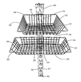
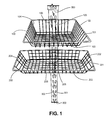
- FIG. 1 is a photograph showing two basket components attached to a support member of a shelving system.
- FIG. 2 is a photograph of five distinct types of hooks hanging on a support member of a shelving system.
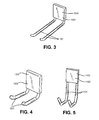
- FIG. 3 illustrates one embodiment of a two prong hook.
- the two pronged hook in this photograph comprises a square shaped backing means, made of metal, and the hooks are affixed to the backing means and are coated with rubber, foam, or similar type of material.
- the hooks are each approximately 8 inches in length and the front surface of the backing means is visible.
- FIG. 4 illustrates one embodiment of a two prong hook.
- the two pronged hook in this photograph comprises a square shaped backing means, made of metal, and the hooks protrude from the backing means, are affixed to the backing means and are coated with rubber, foam, or similar type of material.
- the hooks are each approximately 4 inches in length and the front surface of the backing means is visible.
- FIG. 5 illustrates one embodiment of a two-pronged J-shaped hook.
- the two pronged J-shaped hook in this photograph comprises a square shaped backing means, made of metal, and the J-shaped hooks protrude from the backing means, are affixed to the backing means and are coated with rubber, foam, or similar type of material.
- the front surface of the backing means is visible in this picture.
- FIG. 6 illustrates one embodiment of a multiuse hook.
- the multiuse hook in this photograph comprises a square shaped backing means, made of metal, and the hook is formed as a C-shape, protrudes frontwardly from the backing means, and is affixed to the backing means and is coated with rubber, foam, or similar type of material.
- the hook is approximately 9 inches in length and the front surface of the backing means is visible.
- FIG. 7 illustrates one embodiment of a multiuse hook.
- the multiuse hook in this photograph comprises a square shaped backing means, made of metal, and the hook is formed as a C-shape, protrudes from the backing means, and is affixed to the backing means and is coated with rubber, foam, or similar type of material.
- the hook is approximately 5 inches in length and the front surface of the backing means is visible.
- FIG. 8 illustrates one embodiment of a small basket caddy.
- the caddy in this photograph is formed of wire in a grid pattern, and has a bottom and four sides.
- the caddy protrudes outwardly from the backing means.
- the four sides are perpendicular to the bottom.
- the wire is coated with a plastic or other coating material.
- the front surface of the backing means is visible in this picture.
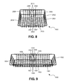
- FIG. 9 illustrates one embodiment of a large basket caddy.
- the caddy in this photograph is formed of wire in a grid pattern, and has a bottom and four sides. The four sides are perpendicular to the bottom.
- the caddy protrudes outwardly from the backing means.
- the wire is coated with a plastic or other coating material.
- the front surface of the backing means is visible in this picture.
- FIG. 10 illustrates one embodiment of a multitool holder.
- the multitool holder depicted has two bars of the same length, parallel to each other, and the two bars are affixed at a ninety degree angle to a backing means.
- the two bars protrude outwardly from the backing means.
- Visible in the picture is the front surface of the backing means, and the backing means contains two holes. One hole is placed near but not touching the uppermost, top edge of the backing means. The other hole is placed near but not touching the lowermost, bottom edge of the backing means.
- FIG. 11 illustrates another embodiment of a multitool holder.
- the multitool holder depicted had two bars of the same length, parallel to each other, and the two bars are affixed at a ninety degree angle to a backing means, thus protruding outwardly from the backing means. Visible in the picture is the front surface of the backing means, and the backing means contains two holes. One hole is placed near but not touching the uppermost, top edge of the backing means. The other hole is placed near but not touching the lowermost, bottom edge of the backing means.
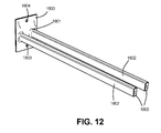
- FIG. 12 illustrates another embodiment of a multitool holder.
- the multitool holder depicted has two bars of the same length, parallel to each other, and the two bars are affixed at a ninety degree angle to a backing means, thus the two bars protrude outwardly from the backing means. Visible in the picture is the front surface of the backing means, and the backing means contains two holes. One hole is placed near but not touching the uppermost, top edge of the backing means. The other hole is placed near but not touching the lowermost, bottom edge of the backing means.
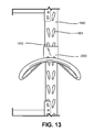
- FIG. 13 illustrates one embodiment of a large multiuse hook attached to a shelving support means.
- the square shaped backing means of the multiuse hook is attached to a shelving support means.
- FIG. 14 illustrates the back surface of the backing means of a multiuse hook.
- the backing means is made of metal or other material.
- Arising from and protruding outwardly from the attachment surface of the backing means are two flanges. Each flange is identical and each flange is oriented to opposite directions.
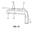
- FIG. 15 illustrates the side view of the backing means of a multiuse hook. Visible in the picture are the two flanges that arise from and protrude outwardly from the back surface of the backing means of the multiuse hook.
- FIG. 16 illustrates the flanges of a backing means of an embodiment of a component of Applicants' invention, where the flanges are secured into the existing openings of the back side of a shelving unit support member.
- the flanges can be described as 2 teeth protruding outwardly from the back side of the backing means. In this picture, the flanges (or teeth) have slid into place and locked into pair of corresponding openings of the shelving unit support member and thereby provide a secure attachment of the component to the shelving unit support member or shelving unit frame.
- Retailers and marketing professionals are constantly seeking to attract the attention of customers to new products and new uses for existing products. This is often a difficult undertaking, as retail and commercial shelf space is usually at a premium and the space requirements of products vary widely. Additionally, retailers, marketers and producers of goods know that in order to sell products, moving inventory to different locations throughout a facility, such as, but not including stores, shopping areas, or warehouses, can often spark the interest of customers. There is value in making the merchandise more accessible, easier to reach, and easier to see, as increased ease of shopping or visibility of products results in increased sales.
- being able to move the location of products to unexpected areas of the shopping venue places products in the path of customers who may not be looking for a particular product, but when the customer sees the product, the customer associates the product with a new use or perhaps becomes aware of it for the first time.
- Retail and commercial floor space is costly. Having flexible, optional, and/or alternative ways to enhance retail and commercial product placement is beneficial to owners and consumers.
- a commonly used shelving system for display or storage in retail, warehouse and commercial establishments is the slat wall-type system. These systems are very industrial looking, and have heavy brackets and limited options with the sizes of backboard and length of shelves
- This invention provides an easily mounted adjustable shelving system and components for the shelving system, for retail, commercial, warehouse and residential purposes.
- the shelving systems and components of the invention work easily with existing shelving systems, so additional investment in the primary shelving systems of products is not necessary.
- the adjustable shelving systems of the invention include components such as baskets, tubs, and barrels of many shapes and sizes (including but not limited to rectangular, square, oval, conical or round shape); hooks and prongs (including but not limited to those having smooth coatings, wire coatings or rubberized coatings, having various lengths and capable of holding various weights and sizes) having various shapes and sizes, and having various lengths and strength capacities; multi-use hooks and prongs of various shapes and sizes, as well as various lengths and strength capacities; caddies of all sizes and shapes; and multi-tool holders of various shapes, sizes, lengths and strength capacities.
- the adjustable shelving system and components of the present invention address the need for more elegant and adjustable systems that easily work with existing shelving systems and are not industrial looking and are able to complement the display of a retail shop, business premises or home.
- the adjustable shelving system and components of the present invention overcome or alleviate shortcomings in existing products by providing an improved shelving system, as well as providing alternatives to enhance and improve retail and other shelving systems.
- the adjustable shelving system and components of the adjustable shelving system described herein comprise a backing means.
- the backing means in certain embodiments, has six sides: a front side, a back side, a top side, a bottom side and two end sides.
- the back side of the backing means has 2 or more flange members that arise from the back face of the back side, and protrude in an outward fashion. The flange members fit into and lock into the existing grooves or the receiving means of support members of shelving systems used in commercial, warehouse, retail and home environments.
- the backing means can be fabricated from one or more materials that are resistant to deformation. The materials used for the backing means may be lightweight or heavyweight, depending on aesthetics and/or features required in any component.
- the backing means can be made of a corrosion resistant material.
- the backing means may be coated to provide an impact resistant surface.
- the backing means may be fabricated from materials such as, but not limited to, metal, plastics or composites, and can be made in any color desired.
- the components of the shelving system of the present invention can be removed easily without need for tools, and cannot be accidentally dislodged.
- the components of the shelving system of the present invention are also able to support a significant amount of weight.
- wire basket component 100 is attached to shelving support member 300 via a backing means 106 .
- Wire basket component 100 has 4 sides ( 102 , 103 , 104 and 105 ) and a bottom 101 .
- Wire basket component 200 is attached to shelving support member 300 via a backing means 206 .
- Wire basket component 200 is rectangular, and has 4 sides ( 202 , 203 , 204 and 205 ) and a bottom 201 .
- Shelving support member 300 has openings 301 and 302 for receiving backing means (back side of backing means not shown) of wire basket component.
- FIG. 2 this figure shows, from top to bottom, a two prong hook 500 , a large multiuse hook 600 , a small multiuse hook 700 , a J-shaped hook 800 , and an 8 inch two pronged hook 900 . All hooks are attached to the support member 400 of a shelving system via the backing means (not shown) of each hook.
- the hook 1000 comprises a backing means 1002 and two outwardly facing prongs 1001 .
- FIG. 4 shows another embodiment of a two pronged hook 1200 .
- the hook 1200 comprises a backing means 1202 and two outwardly facing prongs 1201 which are bent at an angle.
- FIG. 5 shows another embodiment of a two pronged hook 1100 .
- the hook 1100 is a J-shaped hook and comprises a backing means 1102 and two outwardly facing prongs 1101 which are bent to make a J-shape.
- FIG. 6 shows another embodiment of a multiuse hook 1300 .
- the hook 1300 comprises a backing means 1302 and a c-shaped hook 1301 , which is bent upwardly, at an angle.
- FIG. 7 shows an embodiment of a multiuse hook 1400 .
- the hook 1400 comprises a backing means 1402 and a c-shaped hook 1401 , which is bent upwardly, at an angle.
- FIG. 8 refers to one embodiment of a wire basket component 2500 that has 4 sides ( 2502 , 2503 , 2504 and 2505 ) and a bottom 2501 .
- Wire basket component 2500 has a backing means 2508 , two flanges 2506 , two openings 2510 adjacent to flanges 2506 , and two openings 2507 adjacent to flanges 2509 .
- FIG. 9 refers to one embodiment of a wire basket component 1500 that has 4 sides ( 1502 , 1503 , 1504 and 1505 ) and a bottom 1501 .
- Wire basket component 1500 has a backing means 1508 , two flanges 1506 , two openings 1510 adjacent to flanges 1506 , and two openings 1507 adjacent to flanges 1509 .
- FIG. 10 refers to one embodiment of a multitool holder 1600 .
- Multitool holder 1600 has two outwardly facing prongs 1602 , a backing means 1601 , and two holes ( 1604 and 1603 ) in said backing means 1601 .
- the ends 1605 of prongs 1602 are flat surfaces.
- FIG. 11 refers to another one embodiment of a multitool holder 1700 .
- Multitool holder 1700 has two outwardly facing prongs 1702 , a backing means 1701 , and two holes ( 1704 and 1703 ) in said backing means 1701 .
- the ends 1705 of prongs 1702 are flat faces.
- FIG. 12 refers to another one embodiment of a multitool holder 1800 .
- Multitool holder 1800 has two outwardly facing prongs 1802 , a backing means 1801 , and two holes ( 1804 and 1803 ) in said backing means 1801 .
- the ends 1805 of prongs 1802 are flat faces.
- FIG. 13 refers to one embodiment of a multiuse hook 2000 securely attached to a support member 1900 of a shelving unit. Shown are the openings 1901 and 1902 in the support member 1900 of the shelving unit.
- FIG. 14 refers to one embodiment of a multiuse hook 2100 . Shown is the back face or back surface 2105 of the backing means of the multiuse hook 2100 . Also shown are the two flanges 2101 and the two openings 2104 adjacent to the flanges 2101 , and a hole in the backing means of the hook 2100 . Partially visible is the hook 2103 of the multiuse hook 2100 .
- FIG. 15 refers to the side view of one embodiment of a multiuse hook 2200 . Shown is one side surface 2201 of the backing means of the hook 2200 , the two flanges 2202 , and the hole 2203 in the back face 2205 of the backing means of the hook 2200 . Partially visible is the hook 2204 of the multiuse hook 2200 . Not shown are the adjacent openings to the two flanges 2202 in the backing means.
- FIG. 16 shows the back view of the support member 2300 of a shelving unit (not shown), having a pair of openings 2301 and another pair of openings 2302 . Also shown are two flanges 2401 of a backing member 2400 of one embodiment of a component of the invention, and another two flanges 2402 of the backing member 2400 of the same embodiment of the component of the invention.
- references in the specification to “one embodiment”, “an embodiment”, etc., indicate that the embodiment described may include a particular aspect, feature, structure, or characteristic, but not every embodiment necessarily includes that aspect, feature, structure, or characteristic. Moreover, such phrases may, but do not necessarily, refer to the same embodiment referred to in other portions of the specification. Further, when a particular aspect, feature, structure, or characteristic is described in connection with an embodiment, it is within the knowledge of one skilled in the art to affect or connect such aspect, feature, structure, or characteristic with other embodiments, whether or not explicitly described.
- the invention encompasses not only the entire group listed as a whole, but each member of the group individually and all possible subgroups of the main group. Additionally, for all purposes, the invention encompasses not only the main group, but also the main group absent one or more of the group members.
Landscapes
- Supports Or Holders For Household Use (AREA)
Abstract
The invention provides novel adjustable shelving systems and components for shelving systems.
Description
- A commonly used shelving system in retail shops and commercial shops is the slat wall-type system which is very industrial looking, having heavy brackets and limited options regarding the sizes and configurations of backboards and length of shelves. Retailers and marketing professionals are constantly seeking new ways of attracting the interest or attention of purchasers, as well as making products easier to find.
- The invention provides novel adjustable shelving systems and components for shelving systems. In one embodiment, provided is a component for a shelving system, comprising a backing means having planar faces, wherein one planar face comprises two or more flanges that protrude from said planar face, and a means for holding or containing items, wherein said means for holding or containing items is fixedly secured to a second planar face of said backing means.
- The following drawings form part of the specification and are included to further demonstrate certain embodiments or various aspects of the invention. In some instances, embodiments of the invention can be best understood by referring to the accompanying drawings in combination with the detailed description presented herein. The description and accompanying drawings may highlight a certain specific example, or a certain aspect of the invention. However, one skilled in the art will understand that portions of the example or aspects may be used in combination with other examples or aspects of the invention.
-
FIG. 1 is a photograph showing two basket components attached to a support member of a shelving system. -
FIG. 2 is a photograph of five distinct types of hooks hanging on a support member of a shelving system. -
FIG. 3 illustrates one embodiment of a two prong hook. The two pronged hook in this photograph comprises a square shaped backing means, made of metal, and the hooks are affixed to the backing means and are coated with rubber, foam, or similar type of material. In this picture, the hooks are each approximately 8 inches in length and the front surface of the backing means is visible. -
FIG. 4 illustrates one embodiment of a two prong hook. The two pronged hook in this photograph comprises a square shaped backing means, made of metal, and the hooks protrude from the backing means, are affixed to the backing means and are coated with rubber, foam, or similar type of material. In this picture, the hooks are each approximately 4 inches in length and the front surface of the backing means is visible. -
FIG. 5 illustrates one embodiment of a two-pronged J-shaped hook. The two pronged J-shaped hook in this photograph comprises a square shaped backing means, made of metal, and the J-shaped hooks protrude from the backing means, are affixed to the backing means and are coated with rubber, foam, or similar type of material. The front surface of the backing means is visible in this picture. -
FIG. 6 illustrates one embodiment of a multiuse hook. The multiuse hook in this photograph comprises a square shaped backing means, made of metal, and the hook is formed as a C-shape, protrudes frontwardly from the backing means, and is affixed to the backing means and is coated with rubber, foam, or similar type of material. In this picture, the hook is approximately 9 inches in length and the front surface of the backing means is visible. -
FIG. 7 illustrates one embodiment of a multiuse hook. The multiuse hook in this photograph comprises a square shaped backing means, made of metal, and the hook is formed as a C-shape, protrudes from the backing means, and is affixed to the backing means and is coated with rubber, foam, or similar type of material. In this picture, the hook is approximately 5 inches in length and the front surface of the backing means is visible. -
FIG. 8 illustrates one embodiment of a small basket caddy. The caddy in this photograph is formed of wire in a grid pattern, and has a bottom and four sides. The caddy protrudes outwardly from the backing means. The four sides are perpendicular to the bottom. The wire is coated with a plastic or other coating material. The front surface of the backing means is visible in this picture. -
FIG. 9 illustrates one embodiment of a large basket caddy. The caddy in this photograph is formed of wire in a grid pattern, and has a bottom and four sides. The four sides are perpendicular to the bottom. The caddy protrudes outwardly from the backing means. The wire is coated with a plastic or other coating material. The front surface of the backing means is visible in this picture. -
FIG. 10 illustrates one embodiment of a multitool holder. The multitool holder depicted has two bars of the same length, parallel to each other, and the two bars are affixed at a ninety degree angle to a backing means. The two bars protrude outwardly from the backing means. Visible in the picture is the front surface of the backing means, and the backing means contains two holes. One hole is placed near but not touching the uppermost, top edge of the backing means. The other hole is placed near but not touching the lowermost, bottom edge of the backing means. -
FIG. 11 illustrates another embodiment of a multitool holder. The multitool holder depicted had two bars of the same length, parallel to each other, and the two bars are affixed at a ninety degree angle to a backing means, thus protruding outwardly from the backing means. Visible in the picture is the front surface of the backing means, and the backing means contains two holes. One hole is placed near but not touching the uppermost, top edge of the backing means. The other hole is placed near but not touching the lowermost, bottom edge of the backing means. -
FIG. 12 illustrates another embodiment of a multitool holder. The multitool holder depicted has two bars of the same length, parallel to each other, and the two bars are affixed at a ninety degree angle to a backing means, thus the two bars protrude outwardly from the backing means. Visible in the picture is the front surface of the backing means, and the backing means contains two holes. One hole is placed near but not touching the uppermost, top edge of the backing means. The other hole is placed near but not touching the lowermost, bottom edge of the backing means. -
FIG. 13 illustrates one embodiment of a large multiuse hook attached to a shelving support means. The square shaped backing means of the multiuse hook is attached to a shelving support means. -
FIG. 14 illustrates the back surface of the backing means of a multiuse hook. The backing means is made of metal or other material. Arising from and protruding outwardly from the attachment surface of the backing means are two flanges. Each flange is identical and each flange is oriented to opposite directions. -
FIG. 15 illustrates the side view of the backing means of a multiuse hook. Visible in the picture are the two flanges that arise from and protrude outwardly from the back surface of the backing means of the multiuse hook. -
FIG. 16 illustrates the flanges of a backing means of an embodiment of a component of Applicants' invention, where the flanges are secured into the existing openings of the back side of a shelving unit support member. The flanges can be described as 2 teeth protruding outwardly from the back side of the backing means. In this picture, the flanges (or teeth) have slid into place and locked into pair of corresponding openings of the shelving unit support member and thereby provide a secure attachment of the component to the shelving unit support member or shelving unit frame. - Retailers and marketing professionals are constantly seeking to attract the attention of customers to new products and new uses for existing products. This is often a difficult undertaking, as retail and commercial shelf space is usually at a premium and the space requirements of products vary widely. Additionally, retailers, marketers and producers of goods know that in order to sell products, moving inventory to different locations throughout a facility, such as, but not including stores, shopping areas, or warehouses, can often spark the interest of customers. There is value in making the merchandise more accessible, easier to reach, and easier to see, as increased ease of shopping or visibility of products results in increased sales. Also, being able to move the location of products to unexpected areas of the shopping venue places products in the path of customers who may not be looking for a particular product, but when the customer sees the product, the customer associates the product with a new use or perhaps becomes aware of it for the first time.
- Retail and commercial floor space is costly. Having flexible, optional, and/or alternative ways to enhance retail and commercial product placement is beneficial to owners and consumers. A commonly used shelving system for display or storage in retail, warehouse and commercial establishments is the slat wall-type system. These systems are very industrial looking, and have heavy brackets and limited options with the sizes of backboard and length of shelves
- This invention provides an easily mounted adjustable shelving system and components for the shelving system, for retail, commercial, warehouse and residential purposes. The shelving systems and components of the invention work easily with existing shelving systems, so additional investment in the primary shelving systems of products is not necessary.
- The adjustable shelving systems of the invention include components such as baskets, tubs, and barrels of many shapes and sizes (including but not limited to rectangular, square, oval, conical or round shape); hooks and prongs (including but not limited to those having smooth coatings, wire coatings or rubberized coatings, having various lengths and capable of holding various weights and sizes) having various shapes and sizes, and having various lengths and strength capacities; multi-use hooks and prongs of various shapes and sizes, as well as various lengths and strength capacities; caddies of all sizes and shapes; and multi-tool holders of various shapes, sizes, lengths and strength capacities.
- The adjustable shelving system and components of the present invention address the need for more elegant and adjustable systems that easily work with existing shelving systems and are not industrial looking and are able to complement the display of a retail shop, business premises or home.
- The adjustable shelving system and components of the present invention overcome or alleviate shortcomings in existing products by providing an improved shelving system, as well as providing alternatives to enhance and improve retail and other shelving systems.
- In certain embodiments, the adjustable shelving system and components of the adjustable shelving system described herein comprise a backing means. The backing means, in certain embodiments, has six sides: a front side, a back side, a top side, a bottom side and two end sides. In certain embodiments, the back side of the backing means has 2 or more flange members that arise from the back face of the back side, and protrude in an outward fashion. The flange members fit into and lock into the existing grooves or the receiving means of support members of shelving systems used in commercial, warehouse, retail and home environments. The backing means can be fabricated from one or more materials that are resistant to deformation. The materials used for the backing means may be lightweight or heavyweight, depending on aesthetics and/or features required in any component. As a non-limiting example, the backing means can be made of a corrosion resistant material. As another non-limiting example, the backing means may be coated to provide an impact resistant surface. The backing means may be fabricated from materials such as, but not limited to, metal, plastics or composites, and can be made in any color desired.
- The components of the shelving system of the present invention can be removed easily without need for tools, and cannot be accidentally dislodged. The components of the shelving system of the present invention are also able to support a significant amount of weight.
- Referring to
FIG. 1 ,wire basket component 100 is attached toshelving support member 300 via a backing means 106.Wire basket component 100 has 4 sides (102, 103, 104 and 105) and a bottom 101.Wire basket component 200 is attached toshelving support member 300 via a backing means 206.Wire basket component 200 is rectangular, and has 4 sides (202, 203, 204 and 205) and a bottom 201.Shelving support member 300 hasopenings - Referring to
FIG. 2 , this figure shows, from top to bottom, a twoprong hook 500, a largemultiuse hook 600, a smallmultiuse hook 700, a J-shapedhook 800, and an 8 inch twopronged hook 900. All hooks are attached to thesupport member 400 of a shelving system via the backing means (not shown) of each hook. - Referring to
FIG. 3 , a twopronged hook 1000 is shown. Thehook 1000 comprises a backing means 1002 and two outwardly facingprongs 1001. -
FIG. 4 shows another embodiment of a twopronged hook 1200. Thehook 1200 comprises a backing means 1202 and two outwardly facingprongs 1201 which are bent at an angle. -
FIG. 5 shows another embodiment of a twopronged hook 1100. Thehook 1100 is a J-shaped hook and comprises a backing means 1102 and two outwardly facingprongs 1101 which are bent to make a J-shape. -
FIG. 6 shows another embodiment of amultiuse hook 1300. Thehook 1300 comprises a backing means 1302 and a c-shapedhook 1301, which is bent upwardly, at an angle. -
FIG. 7 shows an embodiment of amultiuse hook 1400. Thehook 1400 comprises a backing means 1402 and a c-shapedhook 1401, which is bent upwardly, at an angle. -
FIG. 8 refers to one embodiment of awire basket component 2500 that has 4 sides (2502, 2503, 2504 and 2505) and a bottom 2501.Wire basket component 2500 has a backing means 2508, twoflanges 2506, twoopenings 2510 adjacent toflanges 2506, and twoopenings 2507 adjacent toflanges 2509. -
FIG. 9 refers to one embodiment of awire basket component 1500 that has 4 sides (1502, 1503, 1504 and 1505) and a bottom 1501.Wire basket component 1500 has a backing means 1508, twoflanges 1506, twoopenings 1510 adjacent toflanges 1506, and twoopenings 1507 adjacent toflanges 1509. -
FIG. 10 refers to one embodiment of amultitool holder 1600.Multitool holder 1600 has two outwardly facingprongs 1602, a backing means 1601, and two holes (1604 and 1603) in said backing means 1601. The ends 1605 ofprongs 1602 are flat surfaces. -
FIG. 11 refers to another one embodiment of amultitool holder 1700.Multitool holder 1700 has two outwardly facingprongs 1702, a backing means 1701, and two holes (1704 and 1703) in said backing means 1701. The ends 1705 ofprongs 1702 are flat faces. -
FIG. 12 refers to another one embodiment of amultitool holder 1800.Multitool holder 1800 has two outwardly facingprongs 1802, a backing means 1801, and two holes (1804 and 1803) in said backing means 1801. The ends 1805 ofprongs 1802 are flat faces. -
FIG. 13 refers to one embodiment of amultiuse hook 2000 securely attached to asupport member 1900 of a shelving unit. Shown are theopenings support member 1900 of the shelving unit. -
FIG. 14 refers to one embodiment of amultiuse hook 2100. Shown is the back face or backsurface 2105 of the backing means of themultiuse hook 2100. Also shown are the twoflanges 2101 and the twoopenings 2104 adjacent to theflanges 2101, and a hole in the backing means of thehook 2100. Partially visible is thehook 2103 of themultiuse hook 2100. -
FIG. 15 refers to the side view of one embodiment of amultiuse hook 2200. Shown is oneside surface 2201 of the backing means of thehook 2200, the twoflanges 2202, and thehole 2203 in theback face 2205 of the backing means of thehook 2200. Partially visible is thehook 2204 of themultiuse hook 2200. Not shown are the adjacent openings to the twoflanges 2202 in the backing means. -
FIG. 16 shows the back view of thesupport member 2300 of a shelving unit (not shown), having a pair ofopenings 2301 and another pair ofopenings 2302. Also shown are twoflanges 2401 of abacking member 2400 of one embodiment of a component of the invention, and another twoflanges 2402 of thebacking member 2400 of the same embodiment of the component of the invention. - As used herein, the recited terms have the following meanings. All other terms and phrases used in this specification have their ordinary meanings as one of skill in the art would understand.
- References in the specification to “one embodiment”, “an embodiment”, etc., indicate that the embodiment described may include a particular aspect, feature, structure, or characteristic, but not every embodiment necessarily includes that aspect, feature, structure, or characteristic. Moreover, such phrases may, but do not necessarily, refer to the same embodiment referred to in other portions of the specification. Further, when a particular aspect, feature, structure, or characteristic is described in connection with an embodiment, it is within the knowledge of one skilled in the art to affect or connect such aspect, feature, structure, or characteristic with other embodiments, whether or not explicitly described.
- The singular forms “a,” “an,” and “the” include plural reference unless the context clearly dictates otherwise. It is further noted that the claims may be drafted to exclude any optional element. The term “and/or” means any one of the items, any combination of the items, or all of the items with which this term is associated. The phrase “one or more” is readily understood by one of skill in the art, particularly when read in context of its usage.
- One skilled in the art will also readily recognize that where members are grouped together in a common manner, such as in a Markush group, the invention encompasses not only the entire group listed as a whole, but each member of the group individually and all possible subgroups of the main group. Additionally, for all purposes, the invention encompasses not only the main group, but also the main group absent one or more of the group members.
- While specific embodiments have been described above with reference to the disclosed embodiments and examples, such embodiments are only illustrative and do not limit the scope of the invention. Changes and modifications can be made in accordance with ordinary skill in the art without departing from the invention in its broader aspects as defined in the following claims.
- All publications, patents, and patent documents are incorporated by reference herein, as though individually incorporated by reference.
Claims (3)
1. A component for a shelving system, comprising:
a backing means having at least two planar surfaces, wherein one planar surface comprises two or more flanges that protrude from said planar surface, and
a means for holding or containing items, wherein said means for holding or containing items is fixedly secured to a second planar surface on said backing means.
2. The component of claim 1 , wherein the means is a basket, a caddy, a bucket, a barrel, a two-pronged hook, a two-pronged J-shook, a three-pronged hook, or a multiuse hook.
3. The component of claim 1 , wherein the flanges fit securely into the openings of a shelving unit support member.
Priority Applications (1)
| Application Number | Priority Date | Filing Date | Title |
|---|---|---|---|
| US15/726,867 US20180098623A1 (en) | 2016-10-07 | 2017-10-06 | Adjustable shelving system and components |
Applications Claiming Priority (2)
| Application Number | Priority Date | Filing Date | Title |
|---|---|---|---|
| US201662405360P | 2016-10-07 | 2016-10-07 | |
| US15/726,867 US20180098623A1 (en) | 2016-10-07 | 2017-10-06 | Adjustable shelving system and components |
Publications (1)
| Publication Number | Publication Date |
|---|---|
| US20180098623A1 true US20180098623A1 (en) | 2018-04-12 |
Family
ID=61830317
Family Applications (1)
| Application Number | Title | Priority Date | Filing Date |
|---|---|---|---|
| US15/726,867 Abandoned US20180098623A1 (en) | 2016-10-07 | 2017-10-06 | Adjustable shelving system and components |
Country Status (1)
| Country | Link |
|---|---|
| US (1) | US20180098623A1 (en) |
-
2017
- 2017-10-06 US US15/726,867 patent/US20180098623A1/en not_active Abandoned
Similar Documents
| Publication | Publication Date | Title |
|---|---|---|
| US11304553B2 (en) | Hanger system with hanger coupling member | |
| US6189847B1 (en) | Apparatus for attaching a wide range of article supporting fixtures to a variety of support surfaces | |
| EP2907418B1 (en) | End cap for variable display configurations | |
| US20180184816A1 (en) | Small item overstock storage system | |
| US20170318986A1 (en) | Merchandise Display Strip | |
| US8931231B2 (en) | Panel mounting system with removable security cleat | |
| KR200477212Y1 (en) | Display table for umbrella | |
| US6769656B1 (en) | Assembly for supporting and displaying objects | |
| US8499941B2 (en) | Gravity-fed retail display hook | |
| US20040099618A1 (en) | Ambidextrous merchandise fixture and method of displaying merchandise therefrom | |
| US20120068032A1 (en) | Metal Hooked Utility Bracket Assembly | |
| US8939521B2 (en) | Shelf gap spacer device for a merchandise display system | |
| US8016131B2 (en) | Display tray | |
| US8640875B2 (en) | Tray holder tag support | |
| US20130240461A1 (en) | Product display tower | |
| US8511485B2 (en) | Modular wave shaped merchandiser rack | |
| US20180098623A1 (en) | Adjustable shelving system and components | |
| US7798342B2 (en) | Product display for displaying products in an aisle at a retail store | |
| US20110215063A1 (en) | Jewelry Display System | |
| US10019917B1 (en) | Sign holder and sign for a chair | |
| US20100163504A1 (en) | Wall bracket and accessory system | |
| US6588607B2 (en) | Flip pocket merchandise display system | |
| US10687637B2 (en) | Promotion device | |
| US5788089A (en) | Tag molding support | |
| KR200484632Y1 (en) | the exhibition for hair brush |
Legal Events
| Date | Code | Title | Description |
|---|---|---|---|
| AS | Assignment |
Owner name: MICHEL SALES COMPANY, INC., MINNESOTA Free format text: ASSIGNMENT OF ASSIGNORS INTEREST;ASSIGNOR:BATZLER, PATRICK;REEL/FRAME:043861/0543 Effective date: 20171013 |
|
| STCB | Information on status: application discontinuation |
Free format text: ABANDONED -- FAILURE TO RESPOND TO AN OFFICE ACTION |