US20180098610A1 - Case for portable electronic device - Google Patents
Case for portable electronic device Download PDFInfo
- Publication number
- US20180098610A1 US20180098610A1 US15/832,588 US201715832588A US2018098610A1 US 20180098610 A1 US20180098610 A1 US 20180098610A1 US 201715832588 A US201715832588 A US 201715832588A US 2018098610 A1 US2018098610 A1 US 2018098610A1
- Authority
- US
- United States
- Prior art keywords
- case
- frame structure
- camera
- electronic device
- flash
- Prior art date
- Legal status (The legal status is an assumption and is not a legal conclusion. Google has not performed a legal analysis and makes no representation as to the accuracy of the status listed.)
- Abandoned
Links
Images


Classifications
-
- A—HUMAN NECESSITIES
- A45—HAND OR TRAVELLING ARTICLES
- A45C—PURSES; LUGGAGE; HAND CARRIED BAGS
- A45C11/00—Receptacles for purposes not provided for in groups A45C1/00-A45C9/00
-
- A—HUMAN NECESSITIES
- A45—HAND OR TRAVELLING ARTICLES
- A45C—PURSES; LUGGAGE; HAND CARRIED BAGS
- A45C11/00—Receptacles for purposes not provided for in groups A45C1/00-A45C9/00
- A45C11/001—Receptacles for purposes not provided for in groups A45C1/00-A45C9/00 for storing portable audio devices, e.g. headphones or digital music players
-
- A—HUMAN NECESSITIES
- A45—HAND OR TRAVELLING ARTICLES
- A45C—PURSES; LUGGAGE; HAND CARRIED BAGS
- A45C11/00—Receptacles for purposes not provided for in groups A45C1/00-A45C9/00
- A45C11/002—Receptacles for purposes not provided for in groups A45C1/00-A45C9/00 for storing portable handheld communication devices, e.g. pagers or smart phones
-
- A—HUMAN NECESSITIES
- A45—HAND OR TRAVELLING ARTICLES
- A45C—PURSES; LUGGAGE; HAND CARRIED BAGS
- A45C11/00—Receptacles for purposes not provided for in groups A45C1/00-A45C9/00
- A45C11/003—Receptacles for purposes not provided for in groups A45C1/00-A45C9/00 for storing portable computing devices, e.g. laptops, tablets or calculators
-
- A45C2011/001—
-
- A45C2011/002—
-
- A45C2011/003—
Definitions
- PDAs personal digital assistants
- computers smartphones, mobile phones, satellite phones, cellular phones, pagers, music players, MP3 players, media players, digital cameras, video cameras, bar code scanners, global positioning system (GPS) units, and portable game consoles.
- smartphones mobile phones, satellite phones, cellular phones, pagers, music players, MP3 players, media players, digital cameras, video cameras, bar code scanners, global positioning system (GPS) units, and portable game consoles.
- GPS global positioning system
- These portable electronic devices allow people to play and record music, send and receive e-mail, send text messages, browse Web pages, make phone calls, play and record video, take and view pictures, edit documents, and much more. These devices continue to revolutionize the way people interact, learn, connect with other people, conduct business, and find things. They help people manage their daily lives and can be a source of entertainment. These devices can be used to store valuable information including personal information (e.g., phone numbers, financial information, private photos or videos, and favorite music tracks).
- personal information e.g., phone numbers, financial information, private photos or videos, and favorite music tracks.
- these devices are intended to be carried or moved about. As such, these devices are more vulnerable to damage as compared to non-portable devices. These devices are more likely to be accidentally dropped, hit, or scratched. Some types of damage may be cosmetic (e.g., scratch). However, other types of damage may ruin or limit the functionality of the device. Often these devices contain sensitive and fragile components (e.g., screen, camera lens, flash, processors, accelerometers, and sensors). Accidentally dropping the device could render various features unusable.
- sensitive and fragile components e.g., screen, camera lens, flash, processors, accelerometers, and sensors.
- a case for an electronic device protects the electronic device.
- the case has a back of a first material that is relatively rigid and a frame structure with sides of a second material that is relatively elastic and flexible, which absorb shock.
- the first material is a polycarbonate and the second material is a thermoplastic polyurethane, formed together by a co-molding plastic injection process.
- the thermoplastic polyurethane extends around a perimeter of the case.
- the Crate Case is co-molded with dual materials for double the defense.
- the Crate Case is precision-engineered with a tough back shell and shock-absorbing bumper. With a raised bezel around the perimeter of the device, the screen stays protected while the hard shell exterior offers surface protection.
- the impact-resistant Crate Case is designed for full access to all ports and controls.
- the case is designed for the Apple 6 and 7 families, which include the iPhone 6, 6 Plus, 6S, 6S Plus, 7, and 7 Plus.
- the case is sized to accommodate the phone.
- the iPhone 7 has a length of about 138.3 millimeters (5.44 inches), a width of 67.1 millimeters (2.64 inches), and a thickness of 7.1 millimeters (0.28 inches).
- a weight of the iPhone 7 is about 138 grams (4.87 ounces).
- the iPhone 7 Plus has a length of about 158.2 millimeters (6.23 inches), a width of 77.9 millimeters (3.07 inches), and a thickness of 7.3 millimeters (0.29 inches).
- a weight of the iPhone 7 Plus is about 188 grams (6.63 ounces).
- the iPhone 7 includes: Retina HD display, 4.7-inch (diagonal) LED-backlit widescreen, multi-touch display with IPS technology, 1334-by-750-pixel resolution at 326 pixels per inch, and 1400:1 contrast ratio (typical).
- the iPhone 7 Plus includes: Retina HD display, 5.5-inch (diagonal) LED-backlit widescreen, multi-touch display with IPS technology, 1920-by-1080-pixel resolution at 401 pixels per inch, and 1300:1 contrast ratio (typical). Both models include: wide color display (P3), 625 candela per square meter max brightness (typical), dual-domain pixels for wide viewing angles, fingerprint-resistant oleo-phobic coating, support for display of multiple languages and characters simultaneously, display zoom, and reachability.
- the iPhone 7 family is rated IP67 under IEC standard 60529.
- the iPhone 7 has back camera: 12 megapixel camera, f/1.8 aperture, and digital zoom up to 5 times.
- the iPhone 7 Plus has a back camera: 12 MP wide-angle and telephoto cameras, f/1.8 aperture for the wide angle lens, f/2.8 aperture for the telephoto lens, optical zoom at 2 times, and digital zoom up to 10 times.
- a back of the case include a back opening to expose a camera lens and flash of the electronic device.
- a case for a portable electronic device is a single piece design.
- the left side edge of the case has a covered button for the volume up and volume buttons of the phone, and an opening for the ringer control.
- the right side edge of the case has a covered button for on-off button.
- the bottom side edge of the case has three openings, two openings for two speaker-microphones of the phone, and an opening between the two openings for a power connector (e.g., Apple Lightning port) of the phone.
- a power connector e.g., Apple Lightning port
- the sides of the case are slightly curved and wrap around the sides of the device. Further an upper portion of the sides extends to cover an edging of a front of the device. A lower portion of the sides extends to cover a portion of a back of the phone.
- the upper portion retains the phone in the case, such that device is pressed against the second material of the lower portion of the sides.
- the lower portion helps to protect the device from scratches, provides shock absorption, and ensures a tight and secure fit.
- TPE thermoplastic elastomers
- a case for a portable electronic device includes a frame structure (or side structure) and back panel.
- the frame structure is made from a first material.
- the back panel is made from a second material, different from the first material, and the first material has a different shock absorption characteristic from the second material.
- the frame structure includes a side border having an exterior edge and interior edge.
- the exterior and interior edges being separated by a side border width.
- the interior edge surrounds a perimeter of a compartment or cavity for the portable electronic device.
- the back panel is connected to the frame structure, and more specifically, to a first side of the side border.
- the sides of the portable electronic device are cushioned against side impacts by the first material having a thickness of the frame border width.
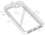
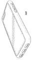
- FIG. 1 shows a first perspective view of a case for a portable electronic device.
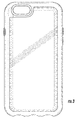
- FIG. 2 shows a front view of the case.
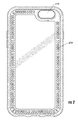
- FIG. 3 shows a back view of the case.
- FIG. 4 shows left-side view of the case.
- FIG. 5 shows a right-side view of the case.
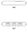
- FIG. 6 shows a top view of the case.
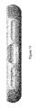
- FIG. 7 shows a bottom view of the case.
- FIG. 8 shows a second perspective view of the case.
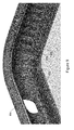
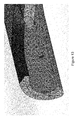
- FIG. 9 shows a perspective view of a corner of the case.
- FIG. 10 shows a perspective cross-sectional view of an upper porter of the case.
- FIG. 11 shows a bottom of the case.
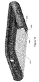
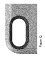
- FIG. 12 shows a camera ring of the case.
- FIG. 13 shows a perspective cross-sectional view of the camera ring.
- FIGS. 1-8 shows various view of a case for a portable electronic device.
- FIG. 1 shows a first perspective view of the case.
- FIG. 2 shows a front view.
- FIG. 3 shows a back view.
- FIG. 4 shows left-side view.
- FIG. 5 shows a right-side view.
- FIG. 6 shows a top view.
- FIG. 7 shows a bottom view.
- FIG. 8 shows a second perspective view.
- FIG. 9 shows a perspective view of a corner of the case.
- FIG. 10 shows a perspective cross-sectional view of an upper porter of the case.
- FIG. 11 shows a bottom of the case.
- FIG. 12 shows a camera ring of the case.
- FIG. 13 shows a perspective cross-sectional view of the camera ring.
- FIG. 2 shows the case in a portrait mode orientation.
- the orientation of the case may change (e.g., landscape mode orientation or upside-down orientation) or vary depending on the point of view or the orientation of the electronic device.
- the case can be used to protect a portable electronic device, such as a smartphone, from damage.
- the case includes a compartment or cavity 105 which holds the portable electronic device.
- the case may include one or more openings (e.g., opening 107 ) or button coverings (e.g., button 109 ) so that a user can access the various features, controls, buttons, switches, dials, knobs, and ports of the electronic device (e.g., touch screen, camera lens, camera flash, power button, headphone jack, and the like) while the electronic device is encased within the case.
- the portable electronic device to be protected is a smartphone.
- this patent application describes the case as being for a smartphone.
- smartphones include the Apple® iPhone®, Samsung® Galaxy®, and there are many others.
- the case can be used with any type of battery-powered portable electronic device, where this device does not necessarily provide telephony functionality.
- the case may be for a portable or handheld gaming device (e.g., Sony® PlayStation® Portable or PSP®, or Nintendo® DSTM), tablet computer (e.g., Apple iPad®) portable or palm-sized computer, personal digital assistant (PDA), pager, audio player, video player, media player (Apple® Touch), cassette player, compact disc (CD) player, digital video disc (DVD) player, camera, video recorder, digital recorder, voice recorder, music recorder, digital audio recorder, or nonvolatile memory storage (e.g., Flash or phase-change memory).
- a portable or handheld gaming device e.g., Sony® PlayStation® Portable or PSP®, or Nintendo® DSTM
- tablet computer e.g., Apple iPad®
- PDA personal digital assistant
- pager e.g., Apple iPad® portable or palm-sized computer
- audio player e.g., video player,
- Apple is a trademark of Apple Computer Incorporated.
- Samsung is a trademark of Samsung Electronics Company Limited.
- Sony is a trademark of Sony Corporation.
- PlayStation and PSP are trademarks of Sony Computer Entertainment Incorporated.
- Nintendo is a trademark of Nintendo Company, Limited.
- the case has a back or bottom 119 and four sides 122 (e.g., left), 124 (e.g., upper or top), 126 (e.g., right), and 128 (e.g., lower or bottom), which form the cavity that holds the portable electronic device.
- the case is a one-piece case; there are not two or more pieces that need to be separated so that the portable electronic device can be inserted into the case. Rather, the portable electronic device can be inserted directly into the case by stretching the elastic sides of the case. Specifically, the sides elastically stretch to fit over the sides and front edge of the portable electronic device and then elastically contract to their original size to hold securely against the sides and front edge of the device. Removal of the portable electronic device from the case is the reverse of insertion.
- the case is made from two different materials, (i) a relatively hard or rigid plastic or polymer material and (ii) a softer, more flexible or elastic plastic or polymer material.
- the back of the case is made of the relatively hard or rigid material while a frame structure which includes the sides are made from the flexible or elastic material.
- a frame structure including the sides extend around the perimeter of the case and is connected to the back. In the case in FIG. 1 , there are four sides and a back.
- the frame structure will have a rubberized or grippier texture as compared to the back panel.
- the sides form the front opening of the case form a closed-polygon shape.
- the closed-polygon shape is a rectangle with rounded corners.
- the closed-polygon shape can have any shape (e.g., square, trapezoid, pentagon, hexagon, octagon, star, circle, arc, or oval).
- the two materials can be formed together through a co-molding or co-injection molding process. During co-molding, the two different materials are thermally bonded or fused together. Alternatively, the two materials can be formed separately and then fitted together (e.g., interlocked or interconnected) to form the case.
- the construction of case can be considered to a composite construction because two or more different materials (e.g., hard or rigid plastic and flexible or elastic plastic) are used to form the case.
- the hard or rigid plastic or polymer material is a polycarbonate (PC) or other plastic or polymer that is harder or more rigid than the side material.
- the hard or rigid plastic or polymer material is translucent, transparent, or clear, so that light can shine or pass through the material. Further, when a phone or other portable electronic device is in the case, a back of the case is visible through the back of the case.
- the hard or rigid plastic or polymer material can be opaque, so light striking one side of the back will not be visible from the other side.
- the two different of the case can be made in any color, combination of colors, combination of hues, or combinations of colors and hues.
- the back material can be a first color or a hue
- the sides can be a second color or hue, where the second color or hue is different from the first color.
- the first and second colors can be different from the color or the camera ring.
- U.S. Pat. No. 8,509,864 describes a camera ring for smartphone or other portable electronic device that prevents glare from flash from affecting the camera and is incorporated by reference.
- U.S. patent application Ser. Nos. 15/333,419, 15/335,375, 15/335,428, and 15/335,430, filed Oct. 26, 2016 are incorporated by reference.
- the flexible or elastic plastic or polymer material is thermoplastic polyurethane (TPU), thermoplastic elastomer (TPE) material, or other plastic or polymer that is softer or more flexible or elastic than the back material.
- TPU thermoplastic polyurethane
- TPE thermoplastic elastomer
- the sides can be made an elastomer, elastic polymer, elastomeric compound, polyurethane, polystyrene, vinyl, polyvinyl chloride (PVC), or nylon, rubber, silicone, and many others.
- An elastomer is a polymer with viscoelasticity (or “elasticity”), generally having low Young's modulus and high failure strain compared with other materials.
- the sides can be made from a composite or combination of multiple relatively flexible or elastic polymers.
- the flexible or elastic plastic or polymer material can also be a foam (e.g., polymer or other substance with trapped bubbles) that provides cushioning or padding.
- foam e.g., polymer or other substance with trapped bubbles
- Some examples of foam include ethylene vinyl acetate (EVA), quantum foam, polyurethane foam (foam rubber), XPS foam, polystyrene, phenolic, or many other manufactured foams.
- EVA is the copolymer of ethylene and vinyl acetate.
- the weight percent vinyl acetate usually varies from 10 to 40 percent, with the remainder being ethylene.
- EVA is often referred to as expanded rubber or foam rubber.
- EVA is a polymer that approaches elastomeric materials in softness and flexibility, yet can be processed like other thermoplastics. The material has good clarity and gloss, low-temperature toughness, stress-crack resistance, hot-melt adhesive waterproof properties, and resistance to ultraviolet (UV) radiation.
- the sides are opaque while the back is translucent. In various other implementations, the sides are opaque translucent and the back is opaque. The sides are translucent and the back is translucent. The sides are translucent while the back is opaque.
- the hard or rigid plastic provides impact protection, such as protection against sharp impacts.
- the sides (of the frame structure) of the case provide shock absorption. To absorb shock, kinetic energy such as generated during the impact against the case is turned into heat and absorbed by the material instead of transferring the impact energy to the device being protected by the case.
- the back material is more rigid than the frame structure or side material, which allows in absorb impact shock.
- the back material e.g., polycarbonate
- the cracked back panel can be replaced with a replacement panel. Or the entire case can be replaced after the impact-absorbing back panel is spent due to an impact.
- the sides can be a foam, and the trapped bubbles in the foam act like compressible springs to absorb the shock. And then after the shock as been absorbed, the frame elastically returns to its original shape (e.g., the bubbles in the foam expand back to their original shape).
- the back material is less elastic than the sides. Thus, a spring constant (Hooke's law) for the back material will less than that for the sides. So, typically, the back material will not absorb as much kinetic energy as the sides.
- An opening of the case may be referred to as an access hole, a combined access hole, or a slot.
- An opening can have any shape.
- a shape of an opening may be a circle, semicircle, square, square with rounded corners, rectangle, rectangle with rounded corners, oval, ellipse, triangle, obround (e.g., a shape having two semicircles connected by parallel lines tangent to their endpoints), crescent, pentagon, hexagon, simple polygon, and so forth.
- An opening may have a closed-shape or figure such as a camera opening 216 ( FIG. 2 ).
- the camera opening is formed as a single opening where the single opening exposes a camera lens and flash of the electronic device.
- this camera opening exposes, makes accessible, or makes visible a camera lens and camera flash of the electronic device.
- the smartphone's camera lens and flash aligns behind the back opening so that the camera lens' view and flash are unobstructed. A picture or video taken with the smartphone in the case will not capture the sides or edges of the camera openings.
- the camera lens and flash of the smartphone are located relatively close to each other.
- Forming the back opening as a single large opening as compared to forming two small openings, each opening aligning with one of the camera lens or flash, has several benefits.
- One benefit is that the camera lens' view will be less likely to be obstructed because there is no case material between the camera lens and the flash.
- a picture taken with the smartphone in the case will not capture case material between the camera lens and flash because there is no case material to capture.
- the light from the flash will be less likely to be obstructed because there is no case material between the camera lens and the flash.
- Camera subjects can be clearly illuminated by the flash because there is no case material between the camera lens and the flash to block light from the flash. This can help to produce pictures where the picture subjects are clearly illuminated with all physical features generally shown and without unwanted shadows.
- the single large back opening feature can help facilitate taking good pictures—especially where ambient light is inadequate (e.g., taking pictures indoors such as at an indoor party, taking pictures at night, taking pictures on a cloudy day, and so forth).
- a shape of the camera opening is an oval or a rectangle having rounded corners. This shape allows the edges (or ends) of the back opening to follow or at least partially follow the curvatures or outlines of the camera lens and flash which are typically circular. Having the shape of the back opening match, partially match, or resemble at least a portion of the outlines or shapes of the camera lens and flash can help to provide protection to the smartphone while still allowing the camera lens and flash to be unobstructed by the case material. That is, the surface area of the back of the smartphone outside of the camera lens and flash will be protected or covered by the case material, but the case material will not overlap or cover the camera lens and flash to block the camera lens and flash. Thus, in some cases it is desirable to select a shape for the back opening where the shape (or at least portions of the shape) resemble the shape of the camera lens, flash, or both.
- the back of a case has does not have a camera opening.
- the back of the case is a continuous surface that is uninterrupted by openings.
- the case may be made of a transparent material (e.g., a clear material) to permit light to pass through the case material and be received by the camera lens of the portable electronic device, to permit light from the flash to pass through the case material and illuminate the subject, or both.
- a transparent material e.g., a clear material
- from the flash passes in a first direction through the case material.
- Ambient light, reflected light from the flash, or both passes in a second direction, opposite the first direction, through the case material to be received by the camera lens.
- Covering the camera lens and flash can further protect the camera lens and flash from damage (e.g., scratches), debris, or both.
- damage e.g., scratches
- the portable electronic device is still able to take pictures, record video, or both because of the transparent case material.
- FIG. 10 shows a cross section of the case, where a hard or rigid plastic case portion 1015 is connected to a flexible or elastic plastic portion 1045 (which may be referred to as a frame structure).
- the hard or rigid plastic case portion can be referred to as a first case material
- the flexible or elastic plastic portion can be referred to as a second case material.
- the back of the case is made form the first case material.
- the frame structure and sides of the case are made from the second case material.
- the cross section of the sides has an arc or C shape.
- the sides of the portable electronic device are held between ends of the C-shaped sides of the case. Opposite sides of the case hold the ends of the device against each other. For example, the bottom side is against the bottom of the device and elastically urges the device and top of the device against the top side of the case, and vice versa.
- the first and second extensions extend from the side.
- the back extends in to the gap formed by this difference, and this gap structure holds the back in place between the first and second extensions of the second case material.
- the second case material extends along an edging 239 of the back.
- FIG. 9 shows details of the structure of the edging and also sides of the case.
- the edging has raised rings 922 , that extend from the surface of the first extension.
- the raised rings are formed along the entire edging of the back side.
- the raised rings have an obround or oval shape, but can be other shapes (e.g., any polygonal shape or circular) in other implementations.
- the back of the portable electronic device is held against the raised rings by an upper edge or lip 934 (e.g., upper end of the C-shaped side).
- the raised rings and their obround or oval shape (with opening within the raised ring) hold the device being protected, and provide a spacing gap, suspending the device in the case, thus providing additional protection for the back of the device.
- the sides of the case also have a structure of raised regions or peaks 946 and lower regions or grooves or valleys 955 , which repeat on the sides of the case.
- the raised regions will be against the sides of the device.
- the raised regions or peaks hold the device being protected, and provide a spacing gap, suspending the device away from the grooves, thus providing additional protection for the sides of the device.
- the upper edge of lip 934 has a thickness that extends away from, for example, the device's screen.
- the lip's thickness will prevent the device's screen from touching the surface. This will help protect the device from possible scratching.
- the corners of the case are rounded, having a particular radius of curvature.
- FIG. 13 shows a cross section of the camera ring and second case material.
- the camera ring is typically made from a different plastic than the flexible or elastic plastic portion and cross-sectional structure shown locks the ring in place.
- the camera ring can be a polycarbonate or other polymer.
- a back of the case from a rigid plastic or polymer material, such as polycarbonate.
- the rigid plastic or polymer material can be translucent or transparent.
- the back of the case can be formed using injection molding.
- sides of the case from a flexible or elastic plastic or polymer material, such as a thermoplastic polyurethane or thermoplastic elastomer.
- the sides of case can also be formed using injection molding.
- the case can be formed using a co-injection molding process.
- the two different materials of the back and sides can be formed together.
- a liquid or uncured plastic is injected or poured into the mold along with a catalyst.
- the mold and plastic is subjected to a temperature to activate the catalyst and material.
- the mold can be opened, and the plastic case portion removed.
- the case portion can be cleaned and flashing removed.
- the mold used in the processing can include features that will form features (e.g., camera-flash opening) of the case described in this application.
- a mold used in processing a case will have a feature that will form the back opening described.
- the mold will have regions where plastic will be (e.g., vessels or channels) and also regions where plastic will be absent (e.g., solid mold material that prevents plastic from curing or forming where the camera-flash opening is desired).
- the case may be made using any manufacturing technique.
- manufacturing techniques that may be used to make a case include injection molding, stereo-lithography, selective laser sintering, fused deposition molding, polyjet, casting (e.g., cast urethane molding), CNC machining, or combinations of these.
- the method includes forming a camera opening through a back of the case.
- the size of the camera opening formed is sufficient to make visible a camera lens and flash of the portable electronic device that is to be placed in the case.
- a length of the camera opening is greater than a width of the camera opening. The length and width are measured in directions transverse to each other.
- a single camera opening exposes two features (e.g., camera lens and flash) of the electronic device.
- a first camera opening exposes camera lens.
- a second camera opening exposes a flash.
- the case is made of a transparent material so that light from the flash can be transmitted through the transparent case material. And ambient light, light reflected from the flash, or both, can be received by the camera lens.
- a case may be made of transparent material and have a single back opening that exposes one of the camera lens or flash.
- the method includes coloring an edge of the back opening a black or other dark color, attaching a black or other dark colored grommet to the back opening, or both.
- the black or dark color can help to reduce the glare from the flash to the camera. This step is optional and is not included in some implementations of the case.
- the edging of the camera-flash opening may be changed to a different color from that of the material.
- edging of the camera-flash opening may be made black or other darker color than that of the case material. Applying the coloration to the openings may be a subsequent step after the case is formed.
- the method may further include forming or applying additional cushioning material to the case, forming other openings to make accessible other features of the portable electronic device, forming covers to be placed over one or more openings of the case, applying a coating to the case (e.g., applying glare reducing coating to camera opening edge), applying a surface treatment to the case (e.g., applying additional rubberized texture to one or more portions the case), or combinations of these.
- a coating e.g., applying glare reducing coating to camera opening edge
- a surface treatment e.g., applying additional rubberized texture to one or more portions the case
- the texture or feel of a material is dependent on material properties (e.g., hardness, modulus, and coefficient of friction), texture, and the TPE wall thickness. These factors may be varied to achieve the desired result. For example, by varying these factors, the sides may be made to be spongy, hard, soft, have a high coefficient of friction, have a low coefficient of friction, and so forth.
- a coefficient of friction (COF) of the sides is greater than a coefficient of friction of the back to which the sides are attached or bonded to.
- COF of the sides is greater than the back of the case to which the sides are attached.
- the coefficient of friction characterizes the degree of force required to move one surface across another—either from a complete stop (static friction) or when the surface is already moving (kinetic friction).
- the sides are designed (or have properties) such that it can provide some level of shock absorption and have a COF such that the electronic device will be secure within the case, but still allows the electronic device to be removed from the case.
- a left sidewall includes a side opening.
- the side opening provides access to ringer controls and covered buttons allow access to the volume buttons of the smartphone.
- the side opening is uncovered so that the user's finger can pass through the side opening and physically touch the ringer or control of the smartphone.
- the button cover covers or at least partially covers the side opening.
- the cover may be, for example, a flexible material such as a rubber.
- the cover can help to protect the buttons of the smartphone from damage and debris, but the buttons are still accessible because the cover can flex when the user pushes the cover which in turn pushes the controls (e.g., depress volume up button by pressing on cover or depress volume down button by pressing on cover).
- FIGS. 7 and 11 show bottom view of different implementations of a case.
- the FIG. 7 implementation can be for an Apple iPhone 6 product
- the FIG. 11 implementation can be for an Apple iPhone 7 product.
- a first bottom opening provides access to, for example, an Apple Lightning port connector and other openings are for the speaker-microphone holes of the device.
- on or more of the bottom openings can be merged together into a single opening.
- the case shown has specific openings sized, shaped, and positioned at particular locations. These openings can be customized for a particular smartphone. It should be appreciated that there may be any number of openings in the upper and lower portions of the case to allow features of a portable electronic device to be accessible to a user. There may be more or fewer openings than that shown in the specific implementation in the figures. For example, a larger opening can be used to replace multiple smaller openings. And a single large opening may be replaced with multiple smaller openings.
- the case includes or is made of polycarbonate.
- the polycarbonate material may be printable or etchable so that images can be made visible on the case as discussed above.
- the case may be made of suitable material such as plastic, nylon, metal (e.g., stainless steel, platinum, or aluminum), wood, or combinations of these.
- the material of the case is a rigid hard plastic. Both upper and lower case portions are made of the same material. The case portions made of a relatively rigid material cannot be stretched as much as, for example, gel, silicone, or rubber, without cracking or breaking.
- the case material is hard or rigid plastic or a non-elastomeric material such as a polycarbonate (e.g., Bayer PC2405 or Makrolon® by Bayer Material Science LLC).
- the case material can be a plastic such as a high density polyethylene, low density polyethylene, thermoplastic, amorphous thermoplastic, or other resin or polymer.
- thermoplastics includes acrylonitrile butadiene styrene (ABS), acrylic, celluloid, cellulose acetate, ethylene-vinyl acetate (EVA), ethylene vinyl alcohol (EVOH), fluoroplastics, ionomers, Kydex®, liquid crystal polymer (LCP), polyacetal (POM or acetal), polyacrylates (acrylic), polyacrylonitrile (PAN or acrylonitrile), polyamide (PA or nylon), polyamide-imide (PAI), polyaryletherketone (PAEK or ketone), polybutadiene (PBD), polybutylene (PB), polybutylene terephthalate (PBT), polycaprolactone (PCL), polychlorotrifluoroethylene (PCTFE), polyethylene terephthalate (PET), polycyclohexylene dimethylene terephthalate (PCT), polyhydroxyalkanoates (PHAs), polyketone (PK), polyester, polyethylene (PE), polyether
- a soft-touch or rubberized coating may be additionally applied to the case surface to help improve a user's grip on the case.
- the soft-touch coating can make the case surface tacky or slightly tacky.
- both upper and lower case portions are made from the same material.
- the upper and lower case portions may be made of different types of materials (e.g., different types of plastics).
- the case material may be (or include), rather than a hard or rigid plastic, a compliant or rubber-like material such as a gel, elastomeric, silicone, or rubber.
- fabric or other materials may be bonded, fused, or otherwise adhered to a surface the case. Such materials may have a decorative patterns.
- some portions of the case can be polished to have a high gloss finish (e.g., similar to glass or a glossy black piano), while other portions will have the soft-touch coating (which is a matte finish).
- all surfaces can have a high gloss finish.
- all surfaces can be coated with the soft-touch coating.
- the high gloss finish can be obtained or achieved by polishing, sanding, rubbing, or buffing the surface with a relatively fine grit material (e.g., sandpaper, polishing cloth, or paste).
- a relatively fine grit material e.g., sandpaper, polishing cloth, or paste.
- polishing can be performed using a buffing machine, such as a rotary buffing machine or other buffing machine.
- the soft-touch coating can be applied by, for example, spraying, brushing, or painting an appropriate coating on the desired surfaces.
- the coating has a thickness of about 0.1 millimeters. But the thickness of the coating can vary, for example, due to manufacturing variations. In other implementations, for example, the thickness can be from about 0.05 millimeters to about 0.3 millimeters. In further implementations, the coating can be less than 0.05 millimeters or greater than 0.3 millimeters.
- the surfaces where the soft-touch coating will be applied do not need to be polished before the coating is applied. However, it may be desirable to buff slightly before applying the coating to ensure the surface is smooth (but not necessarily a high gloss finish) before applying the coating.
- the case can be a material or include materials other than plastic.
- Some examples of case materials include metal (e.g., stainless steel or titanium), glass, transparent or translucent plastic, sapphire, diamond, leather, vinyl, quartz, granite, cloth, fabric, and many others.
Landscapes
- Telephone Set Structure (AREA)
Abstract
Description
- This application claims benefit under 35 U.S.C. § 119(e) from U.S. Provisional Application No. 62/441,318, filed Dec. 31, 2016. This application is also a continuation-in-part of U.S. patent application Ser. No. 29/562,557, filed Apr. 26, 2016. All of the above applications are hereby incorporated herein by reference in their entirety and are to be considered a part of this specification.
- This disclosure is related to a case for portable electronic devices. There are many types of portable electronic devices including personal digital assistants (PDAs), computers, smartphones, mobile phones, satellite phones, cellular phones, pagers, music players, MP3 players, media players, digital cameras, video cameras, bar code scanners, global positioning system (GPS) units, and portable game consoles.
- These portable electronic devices allow people to play and record music, send and receive e-mail, send text messages, browse Web pages, make phone calls, play and record video, take and view pictures, edit documents, and much more. These devices continue to revolutionize the way people interact, learn, connect with other people, conduct business, and find things. They help people manage their daily lives and can be a source of entertainment. These devices can be used to store valuable information including personal information (e.g., phone numbers, financial information, private photos or videos, and favorite music tracks).
- Typically these devices are intended to be carried or moved about. As such, these devices are more vulnerable to damage as compared to non-portable devices. These devices are more likely to be accidentally dropped, hit, or scratched. Some types of damage may be cosmetic (e.g., scratch). However, other types of damage may ruin or limit the functionality of the device. Often these devices contain sensitive and fragile components (e.g., screen, camera lens, flash, processors, accelerometers, and sensors). Accidentally dropping the device could render various features unusable.
- Therefore, it is desirable to protect the electronic device while still allowing features of the device to be easily accessed.
- A case for an electronic device protects the electronic device. The case has a back of a first material that is relatively rigid and a frame structure with sides of a second material that is relatively elastic and flexible, which absorb shock. In a specific implementation, the first material is a polycarbonate and the second material is a thermoplastic polyurethane, formed together by a co-molding plastic injection process. The thermoplastic polyurethane extends around a perimeter of the case. To insert the device, the sides of the case elastically stretch over sides of the device, and then elastically contract to their original size and shape to retain the device in the case.
- A specific implementation of the case is known as the Incase Crate Case product. The Crate Case is co-molded with dual materials for double the defense. The Crate Case is precision-engineered with a tough back shell and shock-absorbing bumper. With a raised bezel around the perimeter of the device, the screen stays protected while the hard shell exterior offers surface protection. The impact-resistant Crate Case is designed for full access to all ports and controls.
- In a specific implementation, the case is designed for the Apple 6 and 7 families, which include the iPhone 6, 6 Plus, 6S, 6S Plus, 7, and 7 Plus. The case is sized to accommodate the phone. The iPhone 7 has a length of about 138.3 millimeters (5.44 inches), a width of 67.1 millimeters (2.64 inches), and a thickness of 7.1 millimeters (0.28 inches). A weight of the iPhone 7 is about 138 grams (4.87 ounces). The iPhone 7 Plus has a length of about 158.2 millimeters (6.23 inches), a width of 77.9 millimeters (3.07 inches), and a thickness of 7.3 millimeters (0.29 inches). A weight of the iPhone 7 Plus is about 188 grams (6.63 ounces).
- The iPhone 7 includes: Retina HD display, 4.7-inch (diagonal) LED-backlit widescreen, multi-touch display with IPS technology, 1334-by-750-pixel resolution at 326 pixels per inch, and 1400:1 contrast ratio (typical). The iPhone 7 Plus includes: Retina HD display, 5.5-inch (diagonal) LED-backlit widescreen, multi-touch display with IPS technology, 1920-by-1080-pixel resolution at 401 pixels per inch, and 1300:1 contrast ratio (typical). Both models include: wide color display (P3), 625 candela per square meter max brightness (typical), dual-domain pixels for wide viewing angles, fingerprint-resistant oleo-phobic coating, support for display of multiple languages and characters simultaneously, display zoom, and reachability. The iPhone 7 family is rated IP67 under IEC standard 60529.
- The iPhone 7 has back camera: 12 megapixel camera, f/1.8 aperture, and digital zoom up to 5 times. The iPhone 7 Plus has a back camera: 12 MP wide-angle and telephoto cameras, f/1.8 aperture for the wide angle lens, f/2.8 aperture for the telephoto lens, optical zoom at 2 times, and digital zoom up to 10 times. A back of the case include a back opening to expose a camera lens and flash of the electronic device.
- In a specific implementation, a case for a portable electronic device is a single piece design. In the second material, the left side edge of the case has a covered button for the volume up and volume buttons of the phone, and an opening for the ringer control. In the second material, the right side edge of the case has a covered button for on-off button. In the second material, the bottom side edge of the case has three openings, two openings for two speaker-microphones of the phone, and an opening between the two openings for a power connector (e.g., Apple Lightning port) of the phone.
- The sides of the case are slightly curved and wrap around the sides of the device. Further an upper portion of the sides extends to cover an edging of a front of the device. A lower portion of the sides extends to cover a portion of a back of the phone. When the device is in the case, the upper portion retains the phone in the case, such that device is pressed against the second material of the lower portion of the sides. The lower portion helps to protect the device from scratches, provides shock absorption, and ensures a tight and secure fit.
- There is not an additional need for the protective strips, stripes, pads, or spines, such as over-molded thermoplastic elastomers (TPE) strips, in the back of the first material. This allows the back of the case to be clear of obstructions. Thus, when the back is made of a transparent or translucent material, there will not be any protective strips or pads to obscure a view of the back of the device.
- In an implementation, a case for a portable electronic device includes a frame structure (or side structure) and back panel. The frame structure is made from a first material. The back panel is made from a second material, different from the first material, and the first material has a different shock absorption characteristic from the second material.
- The frame structure includes a side border having an exterior edge and interior edge. The exterior and interior edges being separated by a side border width. The interior edge surrounds a perimeter of a compartment or cavity for the portable electronic device. The back panel is connected to the frame structure, and more specifically, to a first side of the side border. The sides of the portable electronic device are cushioned against side impacts by the first material having a thickness of the frame border width.
- Other objects, features, and advantages of the present invention will become apparent upon consideration of the following detailed description and the accompanying drawings, in which like reference designations represent like features throughout the figures.
-
FIG. 1 shows a first perspective view of a case for a portable electronic device. -
FIG. 2 shows a front view of the case. -
FIG. 3 shows a back view of the case. -
FIG. 4 shows left-side view of the case. -
FIG. 5 shows a right-side view of the case. -
FIG. 6 shows a top view of the case. -
FIG. 7 shows a bottom view of the case. -
FIG. 8 shows a second perspective view of the case. -
FIG. 9 shows a perspective view of a corner of the case. -
FIG. 10 shows a perspective cross-sectional view of an upper porter of the case. -
FIG. 11 shows a bottom of the case. -
FIG. 12 shows a camera ring of the case. -
FIG. 13 shows a perspective cross-sectional view of the camera ring. -
FIGS. 1-8 shows various view of a case for a portable electronic device.FIG. 1 shows a first perspective view of the case.FIG. 2 shows a front view.FIG. 3 shows a back view.FIG. 4 shows left-side view.FIG. 5 shows a right-side view.FIG. 6 shows a top view.FIG. 7 shows a bottom view.FIG. 8 shows a second perspective view. -
FIG. 9 shows a perspective view of a corner of the case.FIG. 10 shows a perspective cross-sectional view of an upper porter of the case.FIG. 11 shows a bottom of the case.FIG. 12 shows a camera ring of the case.FIG. 13 shows a perspective cross-sectional view of the camera ring. -
FIG. 2 shows the case in a portrait mode orientation. However, the orientation of the case may change (e.g., landscape mode orientation or upside-down orientation) or vary depending on the point of view or the orientation of the electronic device. - This case can be used to protect a portable electronic device, such as a smartphone, from damage. The case includes a compartment or
cavity 105 which holds the portable electronic device. The case may include one or more openings (e.g., opening 107) or button coverings (e.g., button 109) so that a user can access the various features, controls, buttons, switches, dials, knobs, and ports of the electronic device (e.g., touch screen, camera lens, camera flash, power button, headphone jack, and the like) while the electronic device is encased within the case. - Features and aspects of this case may be applied to cases for various portable electronic devices and device types. In a specific implementation, the portable electronic device to be protected is a smartphone. For purposes of discussion, this patent application describes the case as being for a smartphone. Some examples of smartphones include the Apple® iPhone®, Samsung® Galaxy®, and there are many others.
- However, the case can be used with any type of battery-powered portable electronic device, where this device does not necessarily provide telephony functionality. For example, in other implementations, the case may be for a portable or handheld gaming device (e.g., Sony® PlayStation® Portable or PSP®, or Nintendo® DS™), tablet computer (e.g., Apple iPad®) portable or palm-sized computer, personal digital assistant (PDA), pager, audio player, video player, media player (Apple® Touch), cassette player, compact disc (CD) player, digital video disc (DVD) player, camera, video recorder, digital recorder, voice recorder, music recorder, digital audio recorder, or nonvolatile memory storage (e.g., Flash or phase-change memory).
- Trademarks are the property of their respective owners. Apple is a trademark of Apple Computer Incorporated. Samsung is a trademark of Samsung Electronics Company Limited. Sony is a trademark of Sony Corporation. PlayStation and PSP are trademarks of Sony Computer Entertainment Incorporated. Nintendo is a trademark of Nintendo Company, Limited.
- The case has a back or
bottom 119 and four sides 122 (e.g., left), 124 (e.g., upper or top), 126 (e.g., right), and 128 (e.g., lower or bottom), which form the cavity that holds the portable electronic device. The case is a one-piece case; there are not two or more pieces that need to be separated so that the portable electronic device can be inserted into the case. Rather, the portable electronic device can be inserted directly into the case by stretching the elastic sides of the case. Specifically, the sides elastically stretch to fit over the sides and front edge of the portable electronic device and then elastically contract to their original size to hold securely against the sides and front edge of the device. Removal of the portable electronic device from the case is the reverse of insertion. - The case is made from two different materials, (i) a relatively hard or rigid plastic or polymer material and (ii) a softer, more flexible or elastic plastic or polymer material. The back of the case is made of the relatively hard or rigid material while a frame structure which includes the sides are made from the flexible or elastic material. A frame structure including the sides extend around the perimeter of the case and is connected to the back. In the case in
FIG. 1 , there are four sides and a back. The frame structure will have a rubberized or grippier texture as compared to the back panel. - As shown in
FIG. 2 , the sides form the front opening of the case form a closed-polygon shape. In a specific implementation, the closed-polygon shape is a rectangle with rounded corners. In other implementations, the closed-polygon shape can have any shape (e.g., square, trapezoid, pentagon, hexagon, octagon, star, circle, arc, or oval). - The two materials can be formed together through a co-molding or co-injection molding process. During co-molding, the two different materials are thermally bonded or fused together. Alternatively, the two materials can be formed separately and then fitted together (e.g., interlocked or interconnected) to form the case. The construction of case can be considered to a composite construction because two or more different materials (e.g., hard or rigid plastic and flexible or elastic plastic) are used to form the case.
- In a specific implementation, the hard or rigid plastic or polymer material is a polycarbonate (PC) or other plastic or polymer that is harder or more rigid than the side material. In an implementation, the hard or rigid plastic or polymer material is translucent, transparent, or clear, so that light can shine or pass through the material. Further, when a phone or other portable electronic device is in the case, a back of the case is visible through the back of the case. In other implementations, the hard or rigid plastic or polymer material can be opaque, so light striking one side of the back will not be visible from the other side.
- The two different of the case can be made in any color, combination of colors, combination of hues, or combinations of colors and hues. For example, the back material can be a first color or a hue, while the sides can be a second color or hue, where the second color or hue is different from the first color. There is a camera ring, which can be black or another dark color, to reduce or prevent flash glare. The first and second colors can be different from the color or the camera ring. U.S. Pat. No. 8,509,864 describes a camera ring for smartphone or other portable electronic device that prevents glare from flash from affecting the camera and is incorporated by reference. U.S. patent application Ser. Nos. 15/333,419, 15/335,375, 15/335,428, and 15/335,430, filed Oct. 26, 2016 are incorporated by reference.
- In a specific implementation, the flexible or elastic plastic or polymer material is thermoplastic polyurethane (TPU), thermoplastic elastomer (TPE) material, or other plastic or polymer that is softer or more flexible or elastic than the back material. As further example, the sides can be made an elastomer, elastic polymer, elastomeric compound, polyurethane, polystyrene, vinyl, polyvinyl chloride (PVC), or nylon, rubber, silicone, and many others. An elastomer is a polymer with viscoelasticity (or “elasticity”), generally having low Young's modulus and high failure strain compared with other materials. The sides can be made from a composite or combination of multiple relatively flexible or elastic polymers.
- The flexible or elastic plastic or polymer material can also be a foam (e.g., polymer or other substance with trapped bubbles) that provides cushioning or padding. Some examples of foam include ethylene vinyl acetate (EVA), quantum foam, polyurethane foam (foam rubber), XPS foam, polystyrene, phenolic, or many other manufactured foams.
- EVA is the copolymer of ethylene and vinyl acetate. The weight percent vinyl acetate usually varies from 10 to 40 percent, with the remainder being ethylene. EVA is often referred to as expanded rubber or foam rubber. EVA is a polymer that approaches elastomeric materials in softness and flexibility, yet can be processed like other thermoplastics. The material has good clarity and gloss, low-temperature toughness, stress-crack resistance, hot-melt adhesive waterproof properties, and resistance to ultraviolet (UV) radiation.
- In an implementation, the sides are opaque while the back is translucent. In various other implementations, the sides are opaque translucent and the back is opaque. The sides are translucent and the back is translucent. The sides are translucent while the back is opaque.
- The hard or rigid plastic provides impact protection, such as protection against sharp impacts. The sides (of the frame structure) of the case provide shock absorption. To absorb shock, kinetic energy such as generated during the impact against the case is turned into heat and absorbed by the material instead of transferring the impact energy to the device being protected by the case.
- The back material is more rigid than the frame structure or side material, which allows in absorb impact shock. For example, the back material (e.g., polycarbonate) can crack, shatter, or fracture on impact to distribute the energy of the impact. In an implementation, the cracked back panel can be replaced with a replacement panel. Or the entire case can be replaced after the impact-absorbing back panel is spent due to an impact.
- The sides can be a foam, and the trapped bubbles in the foam act like compressible springs to absorb the shock. And then after the shock as been absorbed, the frame elastically returns to its original shape (e.g., the bubbles in the foam expand back to their original shape). In an implementation, the back material is less elastic than the sides. Thus, a spring constant (Hooke's law) for the back material will less than that for the sides. So, typically, the back material will not absorb as much kinetic energy as the sides.
- To allow access to the ports, speakers, and microphone, there are openings. An opening of the case may be referred to as an access hole, a combined access hole, or a slot. An opening can have any shape. For example, a shape of an opening may be a circle, semicircle, square, square with rounded corners, rectangle, rectangle with rounded corners, oval, ellipse, triangle, obround (e.g., a shape having two semicircles connected by parallel lines tangent to their endpoints), crescent, pentagon, hexagon, simple polygon, and so forth. An opening may have a closed-shape or figure such as a camera opening 216 (
FIG. 2 ). - In this specific implementation, the camera opening is formed as a single opening where the single opening exposes a camera lens and flash of the electronic device. When the case is placed on the portable electronic device, this camera opening exposes, makes accessible, or makes visible a camera lens and camera flash of the electronic device. The smartphone's camera lens and flash aligns behind the back opening so that the camera lens' view and flash are unobstructed. A picture or video taken with the smartphone in the case will not capture the sides or edges of the camera openings.
- For some portable electronic devices or smartphones, the camera lens and flash of the smartphone are located relatively close to each other. Forming the back opening as a single large opening as compared to forming two small openings, each opening aligning with one of the camera lens or flash, has several benefits. One benefit is that the camera lens' view will be less likely to be obstructed because there is no case material between the camera lens and the flash. Thus, a picture taken with the smartphone in the case will not capture case material between the camera lens and flash because there is no case material to capture.
- Another benefit is that the light from the flash will be less likely to be obstructed because there is no case material between the camera lens and the flash. Camera subjects can be clearly illuminated by the flash because there is no case material between the camera lens and the flash to block light from the flash. This can help to produce pictures where the picture subjects are clearly illuminated with all physical features generally shown and without unwanted shadows. By not blocking light from the flash, the single large back opening feature can help facilitate taking good pictures—especially where ambient light is inadequate (e.g., taking pictures indoors such as at an indoor party, taking pictures at night, taking pictures on a cloudy day, and so forth).
- In this specific implementation, a shape of the camera opening is an oval or a rectangle having rounded corners. This shape allows the edges (or ends) of the back opening to follow or at least partially follow the curvatures or outlines of the camera lens and flash which are typically circular. Having the shape of the back opening match, partially match, or resemble at least a portion of the outlines or shapes of the camera lens and flash can help to provide protection to the smartphone while still allowing the camera lens and flash to be unobstructed by the case material. That is, the surface area of the back of the smartphone outside of the camera lens and flash will be protected or covered by the case material, but the case material will not overlap or cover the camera lens and flash to block the camera lens and flash. Thus, in some cases it is desirable to select a shape for the back opening where the shape (or at least portions of the shape) resemble the shape of the camera lens, flash, or both.
- In a specific implementation, the back of a case has does not have a camera opening. The back of the case is a continuous surface that is uninterrupted by openings. In this specific implementation, the case may be made of a transparent material (e.g., a clear material) to permit light to pass through the case material and be received by the camera lens of the portable electronic device, to permit light from the flash to pass through the case material and illuminate the subject, or both. In other words, from the flash passes in a first direction through the case material. Ambient light, reflected light from the flash, or both, passes in a second direction, opposite the first direction, through the case material to be received by the camera lens.
- Covering the camera lens and flash can further protect the camera lens and flash from damage (e.g., scratches), debris, or both. However, the portable electronic device is still able to take pictures, record video, or both because of the transparent case material.
-
FIG. 10 shows a cross section of the case, where a hard or rigidplastic case portion 1015 is connected to a flexible or elastic plastic portion 1045 (which may be referred to as a frame structure). The hard or rigid plastic case portion can be referred to as a first case material, and the flexible or elastic plastic portion can be referred to as a second case material. - The back of the case is made form the first case material. The frame structure and sides of the case are made from the second case material. The cross section of the sides has an arc or C shape. The sides of the portable electronic device are held between ends of the C-shaped sides of the case. Opposite sides of the case hold the ends of the device against each other. For example, the bottom side is against the bottom of the device and elastically urges the device and top of the device against the top side of the case, and vice versa.
- The frame structure and sides and second case material extends into the back of the case via a
first extension 1066 and asecond extension 1068. The first extension is against an inside surface ofback 1015, while the second extension is against an outside surface of the back. The first extension extends further away from the side than the second extension. So, when the back is translucent, the first extension is visible through the back. SeeFIG. 3 . In an implementation, a surface of the first extension is flush with the inside surface of back. A surface of the second extension is flush with the outside surface of back. - There is gap and difference in length that the first and second extensions extend from the side. The back extends in to the gap formed by this difference, and this gap structure holds the back in place between the first and second extensions of the second case material. As shown in
FIG. 2 , the second case material extends along an edging 239 of the back. When the portable electronic device is in the case, the edging is against the back of the case. So, the back of the device is suspended in the case by the flexible or elastic plastic material. -
FIG. 9 shows details of the structure of the edging and also sides of the case. The edging has raisedrings 922, that extend from the surface of the first extension. The raised rings are formed along the entire edging of the back side. In a specific implementation, the raised rings have an obround or oval shape, but can be other shapes (e.g., any polygonal shape or circular) in other implementations. The back of the portable electronic device is held against the raised rings by an upper edge or lip 934 (e.g., upper end of the C-shaped side). The raised rings and their obround or oval shape (with opening within the raised ring) hold the device being protected, and provide a spacing gap, suspending the device in the case, thus providing additional protection for the back of the device. - The sides of the case also have a structure of raised regions or peaks 946 and lower regions or grooves or
valleys 955, which repeat on the sides of the case. When a device is in the case, the raised regions will be against the sides of the device. The raised regions or peaks hold the device being protected, and provide a spacing gap, suspending the device away from the grooves, thus providing additional protection for the sides of the device. - As shown in
FIG. 9 , when the device is in the case, the upper edge oflip 934 has a thickness that extends away from, for example, the device's screen. When a user turns the device and places it face down on a surface (e.g., table), the lip's thickness will prevent the device's screen from touching the surface. This will help protect the device from possible scratching. Also, in an implementation, the corners of the case are rounded, having a particular radius of curvature. -
FIG. 13 shows a cross section of the camera ring and second case material. The camera ring is typically made from a different plastic than the flexible or elastic plastic portion and cross-sectional structure shown locks the ring in place. For example, the camera ring can be a polycarbonate or other polymer. - A specific flow for making a case as described in this application is described below. However, it should be understood that the invention is not limited to the specific flows and steps presented. A flow of the invention may have additional steps (not necessarily described in this application), different steps which replace some of the steps presented, fewer steps or a subset of the steps presented, or steps in a different order than presented, or any combination of these. Further, the steps in other implementations of the invention may not be exactly the same as the steps presented and may be modified or altered as appropriate for a particular application or based on the data or situation.
- 1. Forming a back of the case from a rigid plastic or polymer material, such as polycarbonate. The rigid plastic or polymer material can be translucent or transparent. The back of the case can be formed using injection molding.
- 2. Forming sides of the case from a flexible or elastic plastic or polymer material, such as a thermoplastic polyurethane or thermoplastic elastomer. The sides of case can also be formed using injection molding.
- For example, the case can be formed using a co-injection molding process. The two different materials of the back and sides can be formed together. There is a mold of the case portions. A liquid or uncured plastic is injected or poured into the mold along with a catalyst. The mold and plastic is subjected to a temperature to activate the catalyst and material. After a sufficient time for processing to occur, the mold can be opened, and the plastic case portion removed. The case portion can be cleaned and flashing removed. The mold used in the processing can include features that will form features (e.g., camera-flash opening) of the case described in this application.
- 3. Forming a camera opening through a back of the case to make visible a camera lens and flash of a portable electronic device that will be placed in the case. For example, a mold used in processing a case will have a feature that will form the back opening described. The mold will have regions where plastic will be (e.g., vessels or channels) and also regions where plastic will be absent (e.g., solid mold material that prevents plastic from curing or forming where the camera-flash opening is desired).
- The case may be made using any manufacturing technique. Some examples of manufacturing techniques that may be used to make a case include injection molding, stereo-lithography, selective laser sintering, fused deposition molding, polyjet, casting (e.g., cast urethane molding), CNC machining, or combinations of these.
- In a step 3, the method includes forming a camera opening through a back of the case. In a specific implementation, the size of the camera opening formed is sufficient to make visible a camera lens and flash of the portable electronic device that is to be placed in the case. In a specific implementation, a length of the camera opening is greater than a width of the camera opening. The length and width are measured in directions transverse to each other. In this specific implementation, a single camera opening exposes two features (e.g., camera lens and flash) of the electronic device. In another specific implementation, there are two or more camera openings. A first camera opening exposes camera lens. A second camera opening exposes a flash.
- In another specific implementation, no back opening is formed through the back of the case. In this specific implementation, the case is made of a transparent material so that light from the flash can be transmitted through the transparent case material. And ambient light, light reflected from the flash, or both, can be received by the camera lens. A case may be made of transparent material and have a single back opening that exposes one of the camera lens or flash.
- In a specific implementation, the method includes coloring an edge of the back opening a black or other dark color, attaching a black or other dark colored grommet to the back opening, or both. The black or dark color can help to reduce the glare from the flash to the camera. This step is optional and is not included in some implementations of the case.
- The edging of the camera-flash opening (any other openings) may be changed to a different color from that of the material. For example, when the case material is white or other light color, edging of the camera-flash opening (and other openings) may be made black or other darker color than that of the case material. Applying the coloration to the openings may be a subsequent step after the case is formed.
- The method may further include forming or applying additional cushioning material to the case, forming other openings to make accessible other features of the portable electronic device, forming covers to be placed over one or more openings of the case, applying a coating to the case (e.g., applying glare reducing coating to camera opening edge), applying a surface treatment to the case (e.g., applying additional rubberized texture to one or more portions the case), or combinations of these.
- The frame structure and sides of the case of the elastomeric material protect the electronic device from scratches, provide shock absorption (i.e., cushion electronic device), and help to ensure a tight and secure fit for the electronic device. The sides may be described as rubbery or “grippy.”
- Generally, the texture or feel of a material is dependent on material properties (e.g., hardness, modulus, and coefficient of friction), texture, and the TPE wall thickness. These factors may be varied to achieve the desired result. For example, by varying these factors, the sides may be made to be spongy, hard, soft, have a high coefficient of friction, have a low coefficient of friction, and so forth.
- In a specific implementation, a coefficient of friction (COF) of the sides is greater than a coefficient of friction of the back to which the sides are attached or bonded to. For example, the COF of the sides is greater than the back of the case to which the sides are attached. Generally, when two surfaces are dragged flat against each other, the resulting resistance is characterized as friction. The coefficient of friction characterizes the degree of force required to move one surface across another—either from a complete stop (static friction) or when the surface is already moving (kinetic friction).
- Generally, the sides are designed (or have properties) such that it can provide some level of shock absorption and have a COF such that the electronic device will be secure within the case, but still allows the electronic device to be removed from the case.
- As shown in
FIG. 4 , a left sidewall includes a side opening. In this specific implementation, the side opening provides access to ringer controls and covered buttons allow access to the volume buttons of the smartphone. In this specific implementation, the side opening is uncovered so that the user's finger can pass through the side opening and physically touch the ringer or control of the smartphone. - The button cover covers or at least partially covers the side opening. The cover may be, for example, a flexible material such as a rubber. The cover can help to protect the buttons of the smartphone from damage and debris, but the buttons are still accessible because the cover can flex when the user pushes the cover which in turn pushes the controls (e.g., depress volume up button by pressing on cover or depress volume down button by pressing on cover).
-
FIGS. 7 and 11 show bottom view of different implementations of a case. For example theFIG. 7 implementation can be for an Apple iPhone 6 product, while theFIG. 11 implementation can be for an Apple iPhone 7 product. A first bottom opening provides access to, for example, an Apple Lightning port connector and other openings are for the speaker-microphone holes of the device. - In other implementations, on or more of the bottom openings can be merged together into a single opening. For example, there can be a single opening on the bottom, instead of multiple openings as shown.
- The case shown has specific openings sized, shaped, and positioned at particular locations. These openings can be customized for a particular smartphone. It should be appreciated that there may be any number of openings in the upper and lower portions of the case to allow features of a portable electronic device to be accessible to a user. There may be more or fewer openings than that shown in the specific implementation in the figures. For example, a larger opening can be used to replace multiple smaller openings. And a single large opening may be replaced with multiple smaller openings.
- In a specific implementation, the case (or case material) includes or is made of polycarbonate. The polycarbonate material may be printable or etchable so that images can be made visible on the case as discussed above. The case may be made of suitable material such as plastic, nylon, metal (e.g., stainless steel, platinum, or aluminum), wood, or combinations of these. In an implementation, the material of the case is a rigid hard plastic. Both upper and lower case portions are made of the same material. The case portions made of a relatively rigid material cannot be stretched as much as, for example, gel, silicone, or rubber, without cracking or breaking.
- In a specific implementation, the case material is hard or rigid plastic or a non-elastomeric material such as a polycarbonate (e.g., Bayer PC2405 or Makrolon® by Bayer Material Science LLC). The case material can be a plastic such as a high density polyethylene, low density polyethylene, thermoplastic, amorphous thermoplastic, or other resin or polymer.
- Some examples of thermoplastics includes acrylonitrile butadiene styrene (ABS), acrylic, celluloid, cellulose acetate, ethylene-vinyl acetate (EVA), ethylene vinyl alcohol (EVOH), fluoroplastics, ionomers, Kydex®, liquid crystal polymer (LCP), polyacetal (POM or acetal), polyacrylates (acrylic), polyacrylonitrile (PAN or acrylonitrile), polyamide (PA or nylon), polyamide-imide (PAI), polyaryletherketone (PAEK or ketone), polybutadiene (PBD), polybutylene (PB), polybutylene terephthalate (PBT), polycaprolactone (PCL), polychlorotrifluoroethylene (PCTFE), polyethylene terephthalate (PET), polycyclohexylene dimethylene terephthalate (PCT), polyhydroxyalkanoates (PHAs), polyketone (PK), polyester, polyethylene (PE), polyetheretherketone (PEEK), polyetherketoneketone (PEKK), polyetherimide (PEI), polyethersulfone (PES), polysulfone, polyethylenechlorinates (PEC), polyimide (PI), polylactic acid (PLA), polymethylpentene (PMP), polyphenylene oxide (PPO), polyphenylene sulfide (PPS), polyphthalamide (PPA), polypropylene (PP), polystyrene (PS), polysulfone (PSU), polytrimethylene terephthalate (PTT), polyurethane (PU), polyvinyl acetate (PVA), polyvinyl chloride (PVC), polyvinylidene chloride (PVDC), and styrene-acrylonitrile (SAN).
- A soft-touch or rubberized coating may be additionally applied to the case surface to help improve a user's grip on the case. The soft-touch coating can make the case surface tacky or slightly tacky. In an implementation, both upper and lower case portions are made from the same material. However, in other implementations, the upper and lower case portions may be made of different types of materials (e.g., different types of plastics). In other implementations, the case material may be (or include), rather than a hard or rigid plastic, a compliant or rubber-like material such as a gel, elastomeric, silicone, or rubber. In other implementations, fabric or other materials may be bonded, fused, or otherwise adhered to a surface the case. Such materials may have a decorative patterns.
- When a hard plastic is used, some portions of the case can be polished to have a high gloss finish (e.g., similar to glass or a glossy black piano), while other portions will have the soft-touch coating (which is a matte finish). In other implementations, all surfaces can have a high gloss finish. Or, all surfaces can be coated with the soft-touch coating.
- The high gloss finish can be obtained or achieved by polishing, sanding, rubbing, or buffing the surface with a relatively fine grit material (e.g., sandpaper, polishing cloth, or paste). One can polish the plastic with successively finer grit materials until the desired finish is obtained. Polishing can be performed using a buffing machine, such as a rotary buffing machine or other buffing machine.
- The soft-touch coating can be applied by, for example, spraying, brushing, or painting an appropriate coating on the desired surfaces. In a specific implementation, the coating has a thickness of about 0.1 millimeters. But the thickness of the coating can vary, for example, due to manufacturing variations. In other implementations, for example, the thickness can be from about 0.05 millimeters to about 0.3 millimeters. In further implementations, the coating can be less than 0.05 millimeters or greater than 0.3 millimeters. Generally, the surfaces where the soft-touch coating will be applied do not need to be polished before the coating is applied. However, it may be desirable to buff slightly before applying the coating to ensure the surface is smooth (but not necessarily a high gloss finish) before applying the coating.
- In other implementations, the case can be a material or include materials other than plastic. Some examples of case materials include metal (e.g., stainless steel or titanium), glass, transparent or translucent plastic, sapphire, diamond, leather, vinyl, quartz, granite, cloth, fabric, and many others.
- This description of the invention has been presented for the purposes of illustration and description. It is not intended to be exhaustive or to limit the invention to the precise form described, and many modifications and variations are possible in light of the teaching above. The embodiments were chosen and described in order to best explain the principles of the invention and its practical applications. This description will enable others skilled in the art to best utilize and practice the invention in various embodiments and with various modifications as are suited to a particular use. The scope of the invention is defined by the following claims.
Claims (18)
Priority Applications (1)
| Application Number | Priority Date | Filing Date | Title |
|---|---|---|---|
| US15/832,588 US20180098610A1 (en) | 2016-04-26 | 2017-12-05 | Case for portable electronic device |
Applications Claiming Priority (3)
| Application Number | Priority Date | Filing Date | Title |
|---|---|---|---|
| US29562557 | 2016-04-26 | ||
| US201662441318P | 2016-12-31 | 2016-12-31 | |
| US15/832,588 US20180098610A1 (en) | 2016-04-26 | 2017-12-05 | Case for portable electronic device |
Related Parent Applications (1)
| Application Number | Title | Priority Date | Filing Date |
|---|---|---|---|
| US29562557 Continuation-In-Part | 2016-04-26 | 2016-04-26 |
Publications (1)
| Publication Number | Publication Date |
|---|---|
| US20180098610A1 true US20180098610A1 (en) | 2018-04-12 |
Family
ID=61829570
Family Applications (1)
| Application Number | Title | Priority Date | Filing Date |
|---|---|---|---|
| US15/832,588 Abandoned US20180098610A1 (en) | 2016-04-26 | 2017-12-05 | Case for portable electronic device |
Country Status (1)
| Country | Link |
|---|---|
| US (1) | US20180098610A1 (en) |
Cited By (15)
| Publication number | Priority date | Publication date | Assignee | Title |
|---|---|---|---|---|
| RU187718U1 (en) * | 2018-08-27 | 2019-03-15 | Владимир Антонович Ручкин | REPLACEMENT WALL PHONE CASE |
| USD896212S1 (en) * | 2019-07-04 | 2020-09-15 | Shenzhen Chuangxinxin Technology Co., Ltd. | Mobile phone case |
| CN111938289A (en) * | 2020-09-21 | 2020-11-17 | 深圳市太维新材料科技有限公司 | 3C product creative protection package |
| RU208249U1 (en) * | 2021-04-21 | 2021-12-10 | Омар Хасамбекович Набиев | SOLID WOOD PROTECTIVE PHONE CASE |
| CN113940149A (en) * | 2019-05-15 | 2022-01-14 | 泰格斯国际有限责任公司 | Portable electronic device housing with thermal vent |
| USD941297S1 (en) | 2020-02-28 | 2022-01-18 | Catalyst Lifestyle Limited | Bumper for electronic device |
| USD942438S1 (en) * | 2020-02-28 | 2022-02-01 | Catalyst Lifestyle Limited | Bumper for electronic communications device |
| USD945990S1 (en) * | 2020-06-15 | 2022-03-15 | Choton Excellent Technology (Shen Zhen) Co., Ltd | Mobile phone protection shell |
| USD949138S1 (en) * | 2020-06-19 | 2022-04-19 | Speculative Product Design, Llc | Case for an electronic communications device |
| USD952626S1 (en) * | 2021-12-29 | 2022-05-24 | Liqing Gu | Phone case |
| USD984449S1 (en) | 2020-02-28 | 2023-04-25 | Catalyst Lifestyle Limited | Case for electronic device |
| USD984425S1 (en) | 2018-09-11 | 2023-04-25 | Catalyst Lifestyle Limited | Mobile phone protection case |
| US20230246665A1 (en) * | 2020-06-23 | 2023-08-03 | Joseph K. Greco | Shield for a first responder radio |
| USD1057701S1 (en) * | 2024-09-18 | 2025-01-14 | Zehao Zhuang | Phone case |
| USD1101727S1 (en) * | 2021-01-19 | 2025-11-11 | Global Cellular, Inc. | Case for an electronic device |
Citations (22)
| Publication number | Priority date | Publication date | Assignee | Title |
|---|---|---|---|---|
| US20120118773A1 (en) * | 2010-10-12 | 2012-05-17 | TreeFrog Developments, Inc DBA LifeProof | Housing for encasing an object |
| US20120325720A1 (en) * | 2011-06-21 | 2012-12-27 | A.G. Findings & Mfg. Co., Inc. | Portable device case with corner protection element |
| US20130252679A1 (en) * | 2012-03-23 | 2013-09-26 | Beast Kingdom Toys Co.,Ltd. | Protective device for mobile devices |
| US20130292269A1 (en) * | 2012-05-04 | 2013-11-07 | A.G. Findings & Mfg. Co., Inc. | Mobile device case having tension elements |
| US8718731B1 (en) * | 2013-01-30 | 2014-05-06 | Wai Tang | Shock-absorbent electronic device case |
| US20140152890A1 (en) * | 2012-06-01 | 2014-06-05 | Treefrog Developments, Inc. | Housing for encasing an object having a thin profile |
| US20150014188A1 (en) * | 2013-07-10 | 2015-01-15 | AFC Trident, Inc. | Case for a portable electronic device having rims and a material |
| US20150068934A1 (en) * | 2013-08-15 | 2015-03-12 | Urban Armor Gear, Llc | Composite protective case for phones, other portable electronic devices and other apparatus |
| US20150119118A1 (en) * | 2013-10-25 | 2015-04-30 | M-Edge International Corp. | Molded shock resistant case for an electronic device |
| US20150195929A1 (en) * | 2014-01-03 | 2015-07-09 | Tech 21 Licensing Limited | Case for a mobile device with a screen |
| US20150295617A1 (en) * | 2014-04-11 | 2015-10-15 | Catalyst Lifestyle Limited | Waterproof case |
| WO2015181644A2 (en) * | 2014-05-30 | 2015-12-03 | Samsonite Ip Holdings S.Ar.L | Protective cover for an electronic device including impact geometry |
| USD747708S1 (en) * | 2014-12-24 | 2016-01-19 | Tech 21 Licensing Limited | Mobile communications device cover |
| USD747707S1 (en) * | 2014-12-24 | 2016-01-19 | Tech 21 Licensing Limited | Mobile communications device band |
| USD753641S1 (en) * | 2014-09-17 | 2016-04-12 | Tech 21 Licensing Limited | Mobile communications device cover |
| USD754651S1 (en) * | 2014-09-17 | 2016-04-26 | Tech 21 Licensing Limited | Mobile communications device band |
| US20160142522A1 (en) * | 2014-11-14 | 2016-05-19 | Dae-Young Kim | Case having transparent back plate for electronic devices |
| US20160157573A1 (en) * | 2014-12-04 | 2016-06-09 | Samsonite IP Holdings S.ar.I. | Case for an Electronic Device |
| US20170013925A1 (en) * | 2015-07-13 | 2017-01-19 | Incipio, Llc | Mobile device cases and case system with embedded sidewall shock absorber |
| US9788620B1 (en) * | 2016-07-12 | 2017-10-17 | Ideo Plastics Inc. | Electronic device cover |
| USD808372S1 (en) * | 2015-11-24 | 2018-01-23 | Incase Designs Corp. | Case for portable electronic communications device |
| USD814453S1 (en) * | 2016-06-16 | 2018-04-03 | Samsonite Ip Holdings S.Àr.L. | Case for an electronic device |
-
2017
- 2017-12-05 US US15/832,588 patent/US20180098610A1/en not_active Abandoned
Patent Citations (23)
| Publication number | Priority date | Publication date | Assignee | Title |
|---|---|---|---|---|
| US20120118773A1 (en) * | 2010-10-12 | 2012-05-17 | TreeFrog Developments, Inc DBA LifeProof | Housing for encasing an object |
| US20120325720A1 (en) * | 2011-06-21 | 2012-12-27 | A.G. Findings & Mfg. Co., Inc. | Portable device case with corner protection element |
| US20130252679A1 (en) * | 2012-03-23 | 2013-09-26 | Beast Kingdom Toys Co.,Ltd. | Protective device for mobile devices |
| US20130292269A1 (en) * | 2012-05-04 | 2013-11-07 | A.G. Findings & Mfg. Co., Inc. | Mobile device case having tension elements |
| US20140152890A1 (en) * | 2012-06-01 | 2014-06-05 | Treefrog Developments, Inc. | Housing for encasing an object having a thin profile |
| US8718731B1 (en) * | 2013-01-30 | 2014-05-06 | Wai Tang | Shock-absorbent electronic device case |
| US20150014188A1 (en) * | 2013-07-10 | 2015-01-15 | AFC Trident, Inc. | Case for a portable electronic device having rims and a material |
| US20150068934A1 (en) * | 2013-08-15 | 2015-03-12 | Urban Armor Gear, Llc | Composite protective case for phones, other portable electronic devices and other apparatus |
| US20150119118A1 (en) * | 2013-10-25 | 2015-04-30 | M-Edge International Corp. | Molded shock resistant case for an electronic device |
| US20150195929A1 (en) * | 2014-01-03 | 2015-07-09 | Tech 21 Licensing Limited | Case for a mobile device with a screen |
| US20150295617A1 (en) * | 2014-04-11 | 2015-10-15 | Catalyst Lifestyle Limited | Waterproof case |
| WO2015181644A2 (en) * | 2014-05-30 | 2015-12-03 | Samsonite Ip Holdings S.Ar.L | Protective cover for an electronic device including impact geometry |
| US20170187853A1 (en) * | 2014-05-30 | 2017-06-29 | Samsonite IP Holdings S.àr.l | Protective Cover for an Electronic Device Including Impact Geometry |
| USD753641S1 (en) * | 2014-09-17 | 2016-04-12 | Tech 21 Licensing Limited | Mobile communications device cover |
| USD754651S1 (en) * | 2014-09-17 | 2016-04-26 | Tech 21 Licensing Limited | Mobile communications device band |
| US20160142522A1 (en) * | 2014-11-14 | 2016-05-19 | Dae-Young Kim | Case having transparent back plate for electronic devices |
| US20160157573A1 (en) * | 2014-12-04 | 2016-06-09 | Samsonite IP Holdings S.ar.I. | Case for an Electronic Device |
| USD747708S1 (en) * | 2014-12-24 | 2016-01-19 | Tech 21 Licensing Limited | Mobile communications device cover |
| USD747707S1 (en) * | 2014-12-24 | 2016-01-19 | Tech 21 Licensing Limited | Mobile communications device band |
| US20170013925A1 (en) * | 2015-07-13 | 2017-01-19 | Incipio, Llc | Mobile device cases and case system with embedded sidewall shock absorber |
| USD808372S1 (en) * | 2015-11-24 | 2018-01-23 | Incase Designs Corp. | Case for portable electronic communications device |
| USD814453S1 (en) * | 2016-06-16 | 2018-04-03 | Samsonite Ip Holdings S.Àr.L. | Case for an electronic device |
| US9788620B1 (en) * | 2016-07-12 | 2017-10-17 | Ideo Plastics Inc. | Electronic device cover |
Cited By (16)
| Publication number | Priority date | Publication date | Assignee | Title |
|---|---|---|---|---|
| RU187718U1 (en) * | 2018-08-27 | 2019-03-15 | Владимир Антонович Ручкин | REPLACEMENT WALL PHONE CASE |
| USD984425S1 (en) | 2018-09-11 | 2023-04-25 | Catalyst Lifestyle Limited | Mobile phone protection case |
| CN113940149A (en) * | 2019-05-15 | 2022-01-14 | 泰格斯国际有限责任公司 | Portable electronic device housing with thermal vent |
| USD896212S1 (en) * | 2019-07-04 | 2020-09-15 | Shenzhen Chuangxinxin Technology Co., Ltd. | Mobile phone case |
| USD984449S1 (en) | 2020-02-28 | 2023-04-25 | Catalyst Lifestyle Limited | Case for electronic device |
| USD941297S1 (en) | 2020-02-28 | 2022-01-18 | Catalyst Lifestyle Limited | Bumper for electronic device |
| USD942438S1 (en) * | 2020-02-28 | 2022-02-01 | Catalyst Lifestyle Limited | Bumper for electronic communications device |
| USD945990S1 (en) * | 2020-06-15 | 2022-03-15 | Choton Excellent Technology (Shen Zhen) Co., Ltd | Mobile phone protection shell |
| USD949138S1 (en) * | 2020-06-19 | 2022-04-19 | Speculative Product Design, Llc | Case for an electronic communications device |
| US20230246665A1 (en) * | 2020-06-23 | 2023-08-03 | Joseph K. Greco | Shield for a first responder radio |
| US11973527B2 (en) * | 2020-06-23 | 2024-04-30 | Joseph K Greco | Shield for a first responder radio |
| CN111938289A (en) * | 2020-09-21 | 2020-11-17 | 深圳市太维新材料科技有限公司 | 3C product creative protection package |
| USD1101727S1 (en) * | 2021-01-19 | 2025-11-11 | Global Cellular, Inc. | Case for an electronic device |
| RU208249U1 (en) * | 2021-04-21 | 2021-12-10 | Омар Хасамбекович Набиев | SOLID WOOD PROTECTIVE PHONE CASE |
| USD952626S1 (en) * | 2021-12-29 | 2022-05-24 | Liqing Gu | Phone case |
| USD1057701S1 (en) * | 2024-09-18 | 2025-01-14 | Zehao Zhuang | Phone case |
Similar Documents
| Publication | Publication Date | Title |
|---|---|---|
| US20180098610A1 (en) | Case for portable electronic device | |
| US8457701B2 (en) | Case for portable electronic device | |
| US9204697B2 (en) | Protective casing providing impact absorption and water resistance for portable electronic devices | |
| US10667589B2 (en) | Mobile device cases and case system with embedded sidewall shock absorber | |
| US7957524B2 (en) | Protective covering for an electronic device | |
| US9408446B2 (en) | Case for a portable electronic device | |
| US20120088558A1 (en) | Phone case | |
| US20200288833A1 (en) | Mobile device cases and case systems with embedded sidewall shock absorber | |
| US20150296946A1 (en) | Portable computing device case convertible to upright stand | |
| US10206490B2 (en) | Accessory device for electronic device and method for manufacturing the same | |
| US20150014188A1 (en) | Case for a portable electronic device having rims and a material | |
| CN104053328A (en) | Case structures for portable electronic devices | |
| US10236928B2 (en) | Molded mobile device case with storage compartment having hinged access | |
| TW201436691A (en) | Housing structure of portable electronic device | |
| KR101027766B1 (en) | Portable terminal protection waterproof package | |
| US20150370288A1 (en) | Protective enclosures for mobile computing devices | |
| US20180289122A1 (en) | Protective Case for Portable Electronic Device | |
| US20170366217A1 (en) | Providing a seal for a protective mobile device case | |
| US10542802B1 (en) | Case for portable electronic device | |
| US20130032432A1 (en) | Slip Resistant Cover For Portable Electronics | |
| US20160254835A1 (en) | Integrated screen and perimeter protector for an electronic device | |
| US20180271263A1 (en) | Protective Case for Portable Electronic Device | |
| KR101585383B1 (en) | Protecting case for mobile device | |
| US20210314013A1 (en) | Mobile device case with storage compartment | |
| KR101059568B1 (en) | Portable Electronic Device Waterproof Case Assembly Structure |
Legal Events
| Date | Code | Title | Description |
|---|---|---|---|
| AS | Assignment |
Owner name: WELLS FARGO BANK, NATIONAL ASSOCIATION, AS ADMINISTRATIVE AGENT, CALIFORNIA Free format text: SECURITY INTEREST;ASSIGNOR:INCASE DESIGNS CORP.;REEL/FRAME:047247/0438 Effective date: 20180706 Owner name: WELLS FARGO BANK, NATIONAL ASSOCIATION, AS ADMINIS Free format text: SECURITY INTEREST;ASSIGNOR:INCASE DESIGNS CORP.;REEL/FRAME:047247/0438 Effective date: 20180706 |
|
| AS | Assignment |
Owner name: MONROE CAPITAL MANAGEMENT ADVISORS, LLC, ILLINOIS Free format text: SECURITY INTEREST;ASSIGNOR:INCASE DESIGNS CORP.;REEL/FRAME:046466/0325 Effective date: 20180706 |
|
| STPP | Information on status: patent application and granting procedure in general |
Free format text: RESPONSE TO NON-FINAL OFFICE ACTION ENTERED AND FORWARDED TO EXAMINER |
|
| AS | Assignment |
Owner name: INCASE DESIGNS CORP., CALIFORNIA Free format text: ASSIGNMENT OF ASSIGNORS INTEREST;ASSIGNORS:CORRALIZA, STEVEN;HO, WILLIAM;SIGNING DATES FROM 20180130 TO 20180131;REEL/FRAME:048223/0192 |
|
| STPP | Information on status: patent application and granting procedure in general |
Free format text: FINAL REJECTION MAILED |
|
| AS | Assignment |
Owner name: MIDCAP FUNDING IV TRUST, MARYLAND Free format text: SECURITY INTEREST;ASSIGNORS:INCIPIO, LLC;INCASE DESIGNS CORP.;GRIFFIN TECHNOLOGY, LLC;AND OTHERS;REEL/FRAME:050129/0814 Effective date: 20190521 |
|
| AS | Assignment |
Owner name: INCASE DESIGNS CORP., CALIFORNIA Free format text: RELEASE OF SECURITY INTEREST IN PATENTS AT REEL/FRAME NO. 47247/0438;ASSIGNOR:WELLS FARGO BANK, NATIONAL ASSOCIATION, AS ADMINISTRATIVE AGENT;REEL/FRAME:049345/0845 Effective date: 20190521 |
|
| STCB | Information on status: application discontinuation |
Free format text: ABANDONED -- FAILURE TO RESPOND TO AN OFFICE ACTION |
|
| AS | Assignment |
Owner name: SIENA LENDING GROUP LLC, CONNECTICUT Free format text: SECURITY INTEREST;ASSIGNOR:ARMOR ACQUISITION LLC;REEL/FRAME:057112/0057 Effective date: 20210806 |
|
| AS | Assignment |
Owner name: ARMOR ACQUISITION LLC, CALIFORNIA Free format text: ASSIGNMENT OF ASSIGNORS INTEREST;ASSIGNOR:INCASE DESIGNS CORP.;REEL/FRAME:058176/0805 Effective date: 20210806 |
|
| AS | Assignment |
Owner name: VINCI BRANDS LLC, CALIFORNIA Free format text: CHANGE OF NAME;ASSIGNOR:ARMOR ACQUISITION LLC;REEL/FRAME:059912/0179 Effective date: 20210824 |
|
| AS | Assignment |
Owner name: VEVEY LLC, NEW YORK Free format text: ASSIGNMENT OF ASSIGNORS INTEREST;ASSIGNOR:ACS GROUP ACQUISITION LLC;REEL/FRAME:070610/0873 Effective date: 20231201 Owner name: ACS GROUP ACQUISITION LLC, NEW YORK Free format text: ASSIGNMENT OF ASSIGNORS INTEREST;ASSIGNOR:VINCI BRANDS LLC;REEL/FRAME:070610/0783 Effective date: 20231201 |