US20180098604A1 - Jewelry with interchangeable decorative element of various shapes - Google Patents
Jewelry with interchangeable decorative element of various shapes Download PDFInfo
- Publication number
- US20180098604A1 US20180098604A1 US15/728,655 US201715728655A US2018098604A1 US 20180098604 A1 US20180098604 A1 US 20180098604A1 US 201715728655 A US201715728655 A US 201715728655A US 2018098604 A1 US2018098604 A1 US 2018098604A1
- Authority
- US
- United States
- Prior art keywords
- base
- spaced
- sidewall
- apart
- spring element
- Prior art date
- Legal status (The legal status is an assumption and is not a legal conclusion. Google has not performed a legal analysis and makes no representation as to the accuracy of the status listed.)
- Abandoned
Links
- 125000001475 halogen functional group Chemical group 0.000 claims abstract description 49
- 230000002093 peripheral effect Effects 0.000 claims abstract description 14
- 239000010437 gem Substances 0.000 claims description 16
- 229910001751 gemstone Inorganic materials 0.000 claims description 15
- BQCADISMDOOEFD-UHFFFAOYSA-N Silver Chemical compound [Ag] BQCADISMDOOEFD-UHFFFAOYSA-N 0.000 claims description 10
- 229910052709 silver Inorganic materials 0.000 claims description 10
- 239000004332 silver Substances 0.000 claims description 10
- BASFCYQUMIYNBI-UHFFFAOYSA-N platinum Chemical compound [Pt] BASFCYQUMIYNBI-UHFFFAOYSA-N 0.000 claims description 8
- RTAQQCXQSZGOHL-UHFFFAOYSA-N Titanium Chemical compound [Ti] RTAQQCXQSZGOHL-UHFFFAOYSA-N 0.000 claims description 5
- PCHJSUWPFVWCPO-UHFFFAOYSA-N gold Chemical compound [Au] PCHJSUWPFVWCPO-UHFFFAOYSA-N 0.000 claims description 5
- 229910052737 gold Inorganic materials 0.000 claims description 5
- 239000010931 gold Substances 0.000 claims description 5
- 229910052719 titanium Inorganic materials 0.000 claims description 5
- 239000010936 titanium Substances 0.000 claims description 5
- 229910052751 metal Inorganic materials 0.000 claims description 4
- 239000002184 metal Substances 0.000 claims description 4
- 238000000034 method Methods 0.000 claims description 4
- 229910052697 platinum Inorganic materials 0.000 claims description 4
- 239000010970 precious metal Substances 0.000 claims description 4
- -1 argentium silver) Chemical compound 0.000 description 3
- 229910001118 argentium sterling silver Inorganic materials 0.000 description 2
- 230000013011 mating Effects 0.000 description 2
- 229910052703 rhodium Inorganic materials 0.000 description 2
- 239000010948 rhodium Substances 0.000 description 2
- MHOVAHRLVXNVSD-UHFFFAOYSA-N rhodium atom Chemical compound [Rh] MHOVAHRLVXNVSD-UHFFFAOYSA-N 0.000 description 2
- 235000014443 Pyrus communis Nutrition 0.000 description 1
- 229910000831 Steel Inorganic materials 0.000 description 1
- 239000000853 adhesive Substances 0.000 description 1
- 230000001070 adhesive effect Effects 0.000 description 1
- 230000008676 import Effects 0.000 description 1
- 239000000463 material Substances 0.000 description 1
- 238000012986 modification Methods 0.000 description 1
- 230000004048 modification Effects 0.000 description 1
- 239000010959 steel Substances 0.000 description 1
- 229910000898 sterling silver Inorganic materials 0.000 description 1
- 239000010934 sterling silver Substances 0.000 description 1
- 239000004575 stone Substances 0.000 description 1
- 238000005494 tarnishing Methods 0.000 description 1
- 238000003466 welding Methods 0.000 description 1
Images
Classifications
-
- A—HUMAN NECESSITIES
- A44—HABERDASHERY; JEWELLERY
- A44C—PERSONAL ADORNMENTS, e.g. JEWELLERY; COINS
- A44C17/00—Gems or the like
- A44C17/02—Settings for holding gems or the like, e.g. for ornaments or decorations
- A44C17/0208—Settings for holding gems or the like, e.g. for ornaments or decorations removable
- A44C17/0216—Settings for holding gems or the like, e.g. for ornaments or decorations removable with automatic locking action, e.g. by using a spring
-
- A—HUMAN NECESSITIES
- A44—HABERDASHERY; JEWELLERY
- A44C—PERSONAL ADORNMENTS, e.g. JEWELLERY; COINS
- A44C9/00—Finger-rings
- A44C9/0053—Finger-rings having special functions
Definitions
- Embodiments of the present invention relate generally to jewelry, and more particularly, to jewelry having an interchangeable decorative element. Another aspect of the present invention relates to a spring element for jewelry having an interchangeable decorative element.
- the mount includes a base having a foundation wall, a first sidewall surrounding the base wall, a second sidewall spaced apart from and inwardly of the first sidewall, an peripheral recess formed between the first and second sidewalls, and a central recess bounded by the foundation wall and the second sidewall, the central recess being configured to removably receive the decorative element therein, the second sidewall including a plurality of spaced-apart vertical posts on an interior surface thereof; and a spring element positioned in the base between the foundation wall and a bottom end of the second sidewall, the spring element comprising a first plurality of spaced-apart protrusions positioned in the central recess of the base, an inner periphery of the spring element including a first plurality of spaced-apart notches extending from the inner periphery toward an outer periphery of the spring element, each vertical post of the second sidewall of the base being
- One aspect of the present invention is directed to a piece of jewelry including a decorative element including a support member and a jewel, the support member including a first end and an opposing second end, the second end including a plurality of spaced-apart notches; a base having a foundation wall, a first sidewall surrounding the foundation wall, a second sidewall spaced apart from and inwardly of the first sidewall, a peripheral recess formed between the first and second sidewalls, and a central recess bounded by the foundation wall and the second sidewall, the decorative element being removably secured within the central recess of the base, an interior surface of the second sidewall of the base including a plurality of spaced-apart vertical posts and an exterior surface of the second sidewall including a plurality of spaced-apart grooves; a spring element positioned in the base between the foundation wall and a bottom end of the second sidewall, the spring element comprising a first plurality of spaced-apart protrusions positioned in the central recess of
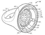
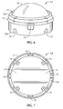
- FIG. 1 is a side perspective view of a piece of jewelry, namely a ring, in accordance with a preferred embodiment of the present invention
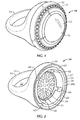
- FIG. 2 is a side perspective view of an assembled base and spring element of the ring of FIG. 1 ;
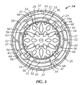
- FIG. 3 is a top perspective view of the assembled base and spring element shown in FIG. 2 ;
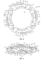
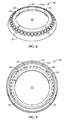
- FIG. 4 is top perspective view of a spring element of the ring of FIG. 1 ;
- FIG. 5 is a side perspective view of the spring element shown in FIG. 4 ;
- FIG. 6 is a side perspective view of a decorative element of the ring of FIG. 1 ;
- FIG. 7 is a bottom perspective view of the decorative element shown in FIG. 6 ;
- FIG. 8 is a top perspective view of a halo of the ring of FIG. 1 ;
- FIG. 9 is bottom perspective view of the halo shown in FIG. 8 ;
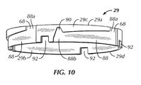
- FIG. 10 is a side perspective view of the inner sidewall 29 of the base 14 .
- the present invention is equally applicable to any type of jewelry which includes a decorative element.
- the present invention may be used for a necklace pendant, an earring, a button, a brooch, a watch, cufflinks and the like.
- the ring 10 includes a base 14 , a spring element 16 (more particularly an annular spring element), and a halo 18 (more particularly an annular halo).
- the base 14 and the halo 18 are both preferably made from a precious metal, such as gold, silver, tarnish resistant silver (e.g., argentium silver), titanium, platinum, or the like, and are preferably made from the same material to provide the look of a conventional ring.
- the base 14 and halo 18 may in some circumstances be plated, such as with rhodium or the like, to prevent tarnishing.
- the halo 18 also preferably includes a decorative design, which may be in the form of a raised or etched pattern (not shown) molded or welded on a visible surface of the halo 18 , additional jewels 21 attached to the visible surface of the halo 18 , or the like. Designs or patterns (not shown) may also be formed on a visible surface of the base 14 .
- the base 14 generally includes a finger hole 22 through which the user extends his or her finger for wearing of the ring 10 .
- the finger hole 22 is generally circular in shape but may be other shapes, as desired.
- multiple bases 14 may be provided, each with a different size and/or shape for the finger hole 22 to allow for interchangeability of the base 14 with the other components (e.g., the decorative element 12 and the halo 18 ) for different-sized fingers.
- the upper portion 26 of the base 14 includes a base wall or foundation wall 31 .
- the upper portion 26 further includes an outer sidewall 27 surrounding the base wall 31 , an inner sidewall 29 spaced apart from and inwardly of the outer sidewall 27 , an annular recess 33 formed between the inner and outer sidewalls 29 , 27 , and a central recess 28 defined by the base wall 31 and the inner sidewall 29 .
- the central recess 28 extends from a distal rim 29 a of the inner sidewall 29 toward the finger hole 22 , but is closed off by the base wall 31 , such that the central recess 28 is configured to receive the decorative element 12 therein.
- a plurality of spaced-apart posts 66 are provided on an interior surface 29 b of the inner sidewall 29 (i.e., the surface proximate the central recess 28 ).
- the posts 66 preferably extend from the base wall 31 upwardly along the interior surface 29 b of the inner sidewall 29 , and are thus vertical posts 66 .
- the cutouts 92 formed in a bottom end 29 d (i.e., opposite the distal rim 29 a ) of the inner sidewall 29 represent the locations of the posts 66 to be provided.
- An exterior surface 29 c, and more particularly an exterior peripheral surface 29 c, of the inner sidewall 29 is preferably provided with a plurality of spaced-apart notches or cutouts 68 .
- each notch 68 is at least slightly offset from each post 66 .
- the exterior peripheral surface of the inner sidewall 29 further includes a plurality of tracks 88 . More particularly, a corresponding elongated track 88 is provided for each notch 68 .
- Each elongated track 88 has a first end 88 a at the respective notch 68 and extends around a portion of the external periphery of the inner sidewall 29 to an opposing second end 88 b.
- a groove 90 is provided at the second end 88 b of each track 88 .
- the second end 88 b of each track 88 is preferably spaced apart from the first end 88 a of an adjacent track 88 .
- the second end 88 b, and more particularly the groove 90 , of each track 88 serves as a travel stop for a respective protrusion 86 of the halo 18 , as is discussed in greater detail below.
- the spring element 16 has a generally flat base surface 39 and an annular configuration or shape.
- the spring element 16 is positioned in the base 14 , and more particularly in the upper portion 26 of the base 14 .
- the spring element 16 is oriented in a horizontal plane and is positioned between the base wall 31 and the bottom end 29 d of the inner sidewall 29 (i.e., the end opposite from the distal rim 29 a ).
- the spring element 16 is preferably made from a metal, such as steel, and includes an inner cavity 17 .
- an outer periphery 19 of the spring element 16 includes a first row of a plurality of spaced apart protrusions 37 .
- Each of the protrusions 37 preferably protrudes upwardly out of the plane of the base surface 39 and has a generally curved or concave shape relative to the base surface 39 .
- Each protrusion 37 preferably has a first end 41 and an opposing second end 43 .
- the second end 43 of each protrusion 37 is preferably spaced apart from the base surface 39 .
- the protrusions 37 are portions of the base surface 39 which are bent out of the plane of the base surface 39 , such that the first end 41 is integrally formed with the base surface 39 and the second end 43 is a distal free end preferably spaced apart from the base surface 29 .
- the second end 43 of each protrusion 37 is preferably at least slightly bent upwardly away from the plane of the base surface 39 (i.e., convex relative to the plane of the base surface 39 ).
- the second end 43 of each protrusion 37 may be provided with or proximate to a travel stop or post (not shown).
- the outer periphery 19 of the spring element 16 further preferably includes a first row of spaced-apart recesses or notches 60 .
- Each notch 60 is preferably formed in the same region as each protrusion 37 . More particularly, each notch 60 is preferably formed at least in the area of the second end 43 of each protrusion 37 . More preferably, each notch 60 extends along the entire length of a respective protrusion 37 and farther past the second end 43 of the respective protrusion 37 for a certain distance.
- an inner periphery 48 of the spring element 16 which surrounds and defines the cavity 17 preferably includes a second row of a plurality of spaced apart protrusions 52 .
- Each of the protrusions 52 preferably protrudes upwardly out of the plane of the base surface 39 and has a generally curved or concave shape relative to the base surface 39 .
- Each protrusion 52 preferably has a first end 54 and an opposing second end 56 .
- the protrusions 52 are portions of the base surface 39 which are bent out of the plane of the base surface 39 , such that the first end 54 is integrally formed with the base surface 39 and the second end 56 is a distal free end.
- the inner periphery 48 preferably includes a second row of spaced apart recesses or notches 64 .
- One notch 64 is preferably formed between each pair of adjacent protrusions 52 .
- Each notch 64 extends from the inner periphery 48 toward the outer periphery 19 .
- the first row of protrusions 37 is preferably spaced apart from the second row of protrusions 52 .
- each outer protrusion 37 is at least slightly offset from each inner protrusion 52 .
- the spring element 16 is positioned between the base wall 31 of the base 14 and the bottom end 29 d of the inner sidewall 29 , such that the first (outer) row of protrusions 37 are positioned in the annular (i.e., peripheral) recess 33 , the second (inner) row of protrusions 52 are positioned in the central recess 28 and each post 66 of the inner sidewall 29 of the base 14 is received within a respective notch 64 of the spring element 16 .
- the spring element 16 is secured to the base 14 in this position under the inner sidewall 29 by laser welding or another similar technique.
- the base 14 and spring element 16 need not specifically interact and engage in this manner.
- the base 14 and the spring element 16 may be formed together as an integral body which would eliminate the need for certain features, such as the notches 64 .
- the decorative element 12 preferably includes a jewel or stone 70 and a cylindrical base or bezel 72 that receives and holds the jewel 70 in place.
- the cylindrical base 72 preferably includes a central cavity 74 configured to receive and hold the jewel 70 .
- the cylindrical base 72 preferably includes a first or top end 72 a, an opposing second or bottom end 72 b and a plurality of spaced-apart prongs 76 extending from the cylindrical sidewall of the base 72 inwardly toward the cavity 74 between the top and bottom ends 72 a, 72 b.
- the spaced-apart prongs 76 support the jewel 70 .
- the jewel 70 may be fixed within the base 72 by way of a friction fit, mechanical fastener, adhesive, or other methods well known to those of ordinary skill in the art to secure precious in a jewelry setting.
- the base 72 is preferably made from a metal, such as, but not limited to, sterling silver, tarnish resistant silver (e.g., argentium silver), gold, platinum, titanium, or the like, and may be plated with rhodium or the like.
- the base 72 also protects the edges of the jewel 70 from contact with other components of the ring 10 , which may cause wear or damage to the jewel 70 .
- the second (bottom) end 72 b of the cylindrical base 72 preferably includes a plurality of spaced-apart notches or recesses 78 .
- the bottom end 72 b of the cylindrical base 72 includes four notches 78 .
- the decorative element 12 is positioned within the central recess 28 of the base 14 .
- the bottom end 72 b of the base 72 of the decorative element 12 is supported by the inner row of spaced-apart protrusions 52 in a raised manner (i.e., raised off of the base wall 31 of the upper portion 26 of the base 14 ).
- each notch 78 of the bottom end 72 b of the base 72 mates with, and more particularly receives, a respective one of the posts 66 formed on the interior surface of the inner sidewall 29 in the central recess 28 .
- the mating of the notches 78 and posts 66 prevents rotation of the decorative element 12 with respect to the base 14 while the halo 18 is being attached to the base 14 , as will be described in more detail below.
- the halo 18 includes a central channel 32 extending therethrough.
- the halo 18 is a generally cylindrically shaped sleeve. At least a portion of the decorative element 12 is received within the channel 32 as the halo 18 secures the decorative element 12 to the base 14 of the ring 10 .
- the channel 32 extends from an first or top end 80 of the halo 18 to an opposing second or bottom end 82 of the halo 18 .
- the channel 32 is also at least partially bounded by a cylindrical sidewall 84 extending from the bottom end 82 toward the top end 80 .
- a plurality of spaced apart protrusions 86 are formed on the interior surface 84 a of the sidewall 84 .
- the decorative element 12 and particularly the jewel 70 , and the halo 18 are not limited to a circular shape, but rather may have any suitable shape, such as an oval, a rectangle, a square, a pear, a teardrop and the like.
- the base of these components is still preferably circular so as to rotate about and engage with the base 14 of the ring 10 as discussed herein.
- the halo 18 and decorative element 12 may be provided as an integral or fixedly attached single element (not shown) (also known as a crown).
- the base 14 of the ring 10 may be the same as described above or may be altered if necessary accommodate the integral element (e.g., the crown).
- the spring element 16 is positioned and secured in the base 14 as described above (alternatively, the base 14 and spring element 16 may be integrally formed), the decorative element 12 is positioned within the central recess 28 of the base 14 as described above, and the halo 18 is removably positioned on and attached to the top of the base 14 (alternatively the decorative element 12 and halo 18 may be integrally formed), such that the decorative element 12 is received in the channel 32 and the sidewall 84 of the halo 18 is received in the annular recess 33 of the base 14 .
- each protrusion 86 of the halo 18 mates with a respective notch 68 formed in the exterior peripheral surface of the inner sidewall 29 of the base 14 .
- the halo 18 is rotated in a first direction, preferably a clockwise direction, relative to the base 14 , which causes each protrusion 86 to travel along the curved contour of a respective elongated track 88 on the exterior surface 29 c of the inner sidewall 29 of the base 14 . More particularly, each protrusion 86 of the halo 18 is first received in a notch 68 , which corresponds to the first end 88 a of the track 88 .
- the protrusion 86 travels along the elongated track 88 toward the second end 88 b.
- the halo 18 is to be rotated in the first direction until each protrusion 86 is received in the groove 90 at the second end 88 b of the track 88 .
- the mating of the protrusions 86 and grooves 90 prevents further rotation of the halo 18 with respect to the base 14 in the first direction.
- the halo 18 is rotated in a second direction which is opposite to the first direction (e.g., preferably a counter-clockwise direction), in order to cause the protrusions 86 to be brought out of a mated configuration with the grooves 90 at the second ends 88 b of the tracks 88 . That is, sufficient torque must be applied in the second direction so as to cause each protrusion 86 to be removed from a respective groove 90 and subsequently travel from the second end 88 b toward the first end 88 a of the track 88 , until the protrusion 86 is once again mated with the respective notch 68 of the base 14 . Then, the halo 18 may be lifted from the base 14 for changing of the decorative element 12 .
- the first direction e.g., preferably a counter-clockwise direction
Landscapes
- Adornments (AREA)
Abstract
A mount for removably mounting a decorative element is provided. The mount includes a base, a spring element positioned in the base and a halo configured to be removably secured to the base. The base has a foundation wall, a first sidewall surrounding the base wall, a second sidewall spaced apart from and inwardly of the first sidewall, a peripheral recess formed between the first and second sidewalls, and a central recess bounded by the foundation wall and the second sidewall. The second sidewall includes a plurality of spaced-apart vertical posts on an interior surface thereof. The spring element includes a plurality of spaced-apart protrusions positioned in the central recess of the base configured to support the decorative element. An inner periphery of the spring element includes a plurality of spaced-apart notches, and each vertical post of the second sidewall of the base is received within a respective notch.
Description
- This application claims priority to U.S. Provisional Patent Application No. 62/406,221, filed on Oct. 10, 2016, entitled “Jewelry with Interchangeable Decorative Element of Various Shapes,” the entire contents of which are incorporated by reference herein.
- Embodiments of the present invention relate generally to jewelry, and more particularly, to jewelry having an interchangeable decorative element. Another aspect of the present invention relates to a spring element for jewelry having an interchangeable decorative element.
- In the context of jewelry, typically a jewel or decorative element is permanently set into a jewel setting so that removal thereof is difficult, if not impossible. Thus, a person wishing to vary the look of his or her jewelry is forced to purchase multiple different jewelry elements, which can be expensive, particularly as the body of the jewelry itself is often made from a precious metal, such as gold, silver, titanium, or the like. In addition, in the event that the decorative element is damaged, the jewelry may have to be discarded. Presently there is no viable option for providing jewelry with a decorative element that can be easily removed and replaced.
- It would therefore be desirable to provide jewelry that allows for quick and easy replacement of the decorative element.
- One aspect of the present invention is directed to a mount for removably mounting a decorative element. The mount includes a base having a foundation wall, a first sidewall surrounding the base wall, a second sidewall spaced apart from and inwardly of the first sidewall, an peripheral recess formed between the first and second sidewalls, and a central recess bounded by the foundation wall and the second sidewall, the central recess being configured to removably receive the decorative element therein, the second sidewall including a plurality of spaced-apart vertical posts on an interior surface thereof; and a spring element positioned in the base between the foundation wall and a bottom end of the second sidewall, the spring element comprising a first plurality of spaced-apart protrusions positioned in the central recess of the base, an inner periphery of the spring element including a first plurality of spaced-apart notches extending from the inner periphery toward an outer periphery of the spring element, each vertical post of the second sidewall of the base being received within a respective notch of the first plurality of spaced-apart notches of the spring element.
- One aspect of the present invention is directed to a piece of jewelry including a decorative element including a support member and a jewel, the support member including a first end and an opposing second end, the second end including a plurality of spaced-apart notches; a base having a foundation wall, a first sidewall surrounding the foundation wall, a second sidewall spaced apart from and inwardly of the first sidewall, a peripheral recess formed between the first and second sidewalls, and a central recess bounded by the foundation wall and the second sidewall, the decorative element being removably secured within the central recess of the base, an interior surface of the second sidewall of the base including a plurality of spaced-apart vertical posts and an exterior surface of the second sidewall including a plurality of spaced-apart grooves; a spring element positioned in the base between the foundation wall and a bottom end of the second sidewall, the spring element comprising a first plurality of spaced-apart protrusions positioned in the central recess of the base, an inner periphery of the spring element including a first plurality of spaced-apart notches extending from the inner periphery toward an outer periphery of the spring element, each vertical post of the second sidewall of the base being received within a respective notch of the first plurality of spaced-apart notches of the spring element and within a respective notch of the plurality of spaced-apart notches of the second end of the support member of the decorative element, the second end of the support member of the decorative element being supported by the first plurality of spaced-apart protrusions of the spring element; and a halo including a first end, an opposing second end, a sidewall extending from the second end toward the first end, and a central channel extending from the first end to the second end and configured to removably receive a portion of the decorative element therein, the sidewall of the halo being positioned in the peripheral recess of the base, the second end of the halo including a plurality of spaced-apart protrusions formed on an interior surface of the sidewall, each protrusion of the halo being received within a respective groove of the plurality of spaced-apart grooves formed on the exterior surface of the second sidewall of the base.
- The following detailed description of preferred embodiments of the invention, will be better understood when read in conjunction with the appended drawings. For the purpose of illustration, there is shown in the drawings an embodiment which is presently preferred. It should be understood, however, that the invention is not limited to the precise arrangements and instrumentalities shown.
-
FIG. 1 is a side perspective view of a piece of jewelry, namely a ring, in accordance with a preferred embodiment of the present invention; -
FIG. 2 is a side perspective view of an assembled base and spring element of the ring ofFIG. 1 ; -
FIG. 3 is a top perspective view of the assembled base and spring element shown inFIG. 2 ; -
FIG. 4 is top perspective view of a spring element of the ring ofFIG. 1 ; -
FIG. 5 is a side perspective view of the spring element shown inFIG. 4 ; -
FIG. 6 is a side perspective view of a decorative element of the ring ofFIG. 1 ; -
FIG. 7 is a bottom perspective view of the decorative element shown inFIG. 6 ; -
FIG. 8 is a top perspective view of a halo of the ring ofFIG. 1 ; -
FIG. 9 is bottom perspective view of the halo shown inFIG. 8 ; and -
FIG. 10 is a side perspective view of theinner sidewall 29 of thebase 14. - Certain terminology is used in the following description for convenience only and is not limiting. The words “right”, “left”, “lower”, and “upper” designate directions in the drawings to which reference is made. The words “inwardly” and “outwardly” refer to directions toward and away from, respectively, the geometric center of the piece of jewelry and designated parts thereof. The terminology includes the above-listed words, derivatives thereof, and words of similar import. Additionally, the words “a” and “an” mean “at least one.”
- It will be understood by those skilled in the art that while the below description relates generally to a piece of jewelry in the form of a ring, the present invention is equally applicable to any type of jewelry which includes a decorative element. For example, the present invention may be used for a necklace pendant, an earring, a button, a brooch, a watch, cufflinks and the like.
- Referring to the drawings in detail, there is shown a preferred embodiment of a
ring 10 that is configured to removably receive adecorative element 12, which may be a jewel, precious stone, or the like (seeFIG. 1 ). Thering 10 includes abase 14, a spring element 16 (more particularly an annular spring element), and a halo 18 (more particularly an annular halo). Thebase 14 and thehalo 18 are both preferably made from a precious metal, such as gold, silver, tarnish resistant silver (e.g., argentium silver), titanium, platinum, or the like, and are preferably made from the same material to provide the look of a conventional ring. In addition, thebase 14 andhalo 18 may in some circumstances be plated, such as with rhodium or the like, to prevent tarnishing. Thehalo 18 also preferably includes a decorative design, which may be in the form of a raised or etched pattern (not shown) molded or welded on a visible surface of thehalo 18,additional jewels 21 attached to the visible surface of thehalo 18, or the like. Designs or patterns (not shown) may also be formed on a visible surface of thebase 14. - Referring to
FIGS. 1-3 , thebase 14 generally includes afinger hole 22 through which the user extends his or her finger for wearing of thering 10. Thefinger hole 22 is generally circular in shape but may be other shapes, as desired. In addition,multiple bases 14 may be provided, each with a different size and/or shape for thefinger hole 22 to allow for interchangeability of thebase 14 with the other components (e.g., thedecorative element 12 and the halo 18) for different-sized fingers. - Surrounding the
finger hole 22 are a generally curvedlower portion 24 and a generally cylindrically-shapedupper portion 26. More particularly, theupper portion 26 of thebase 14 includes a base wall orfoundation wall 31. Theupper portion 26 further includes anouter sidewall 27 surrounding thebase wall 31, aninner sidewall 29 spaced apart from and inwardly of theouter sidewall 27, anannular recess 33 formed between the inner andouter sidewalls central recess 28 defined by thebase wall 31 and theinner sidewall 29. More particularly, thecentral recess 28 extends from adistal rim 29 a of theinner sidewall 29 toward thefinger hole 22, but is closed off by thebase wall 31, such that thecentral recess 28 is configured to receive thedecorative element 12 therein. - Referring to
FIGS. 2-3 , a plurality of spaced-apart posts 66 are provided on an interior surface 29 b of the inner sidewall 29 (i.e., the surface proximate the central recess 28). Theposts 66 preferably extend from thebase wall 31 upwardly along the interior surface 29 b of theinner sidewall 29, and are thusvertical posts 66. InFIG. 10 , thecutouts 92 formed in abottom end 29 d (i.e., opposite thedistal rim 29 a) of theinner sidewall 29 represent the locations of theposts 66 to be provided. - An
exterior surface 29 c, and more particularly an exteriorperipheral surface 29 c, of theinner sidewall 29 is preferably provided with a plurality of spaced-apart notches orcutouts 68. Preferably, eachnotch 68 is at least slightly offset from eachpost 66. - Referring to
FIG. 10 , the exterior peripheral surface of theinner sidewall 29 further includes a plurality oftracks 88. More particularly, a correspondingelongated track 88 is provided for eachnotch 68. Eachelongated track 88 has afirst end 88 a at therespective notch 68 and extends around a portion of the external periphery of theinner sidewall 29 to an opposingsecond end 88 b. Agroove 90 is provided at thesecond end 88 b of eachtrack 88. Thesecond end 88 b of eachtrack 88 is preferably spaced apart from thefirst end 88 a of anadjacent track 88. Thesecond end 88 b, and more particularly thegroove 90, of eachtrack 88 serves as a travel stop for arespective protrusion 86 of thehalo 18, as is discussed in greater detail below. - Referring to
FIGS. 4-5 , thespring element 16 has a generallyflat base surface 39 and an annular configuration or shape. Thespring element 16 is positioned in thebase 14, and more particularly in theupper portion 26 of thebase 14. Specifically, thespring element 16 is oriented in a horizontal plane and is positioned between thebase wall 31 and thebottom end 29 d of the inner sidewall 29 (i.e., the end opposite from thedistal rim 29 a). Thespring element 16 is preferably made from a metal, such as steel, and includes aninner cavity 17. - Referring to
FIGS. 4-5 , anouter periphery 19 of thespring element 16 includes a first row of a plurality of spaced apartprotrusions 37. Preferably, there are at least four spaced-apartprotrusions 37. Each of theprotrusions 37 preferably protrudes upwardly out of the plane of thebase surface 39 and has a generally curved or concave shape relative to thebase surface 39. Eachprotrusion 37 preferably has afirst end 41 and an opposingsecond end 43. Thesecond end 43 of eachprotrusion 37 is preferably spaced apart from thebase surface 39. In one embodiment, theprotrusions 37 are portions of thebase surface 39 which are bent out of the plane of thebase surface 39, such that thefirst end 41 is integrally formed with thebase surface 39 and thesecond end 43 is a distal free end preferably spaced apart from thebase surface 29. In one embodiment, thesecond end 43 of eachprotrusion 37 is preferably at least slightly bent upwardly away from the plane of the base surface 39 (i.e., convex relative to the plane of the base surface 39). Alternatively, thesecond end 43 of eachprotrusion 37 may be provided with or proximate to a travel stop or post (not shown). - The
outer periphery 19 of thespring element 16 further preferably includes a first row of spaced-apart recesses ornotches 60. Eachnotch 60 is preferably formed in the same region as eachprotrusion 37. More particularly, eachnotch 60 is preferably formed at least in the area of thesecond end 43 of eachprotrusion 37. More preferably, eachnotch 60 extends along the entire length of arespective protrusion 37 and farther past thesecond end 43 of therespective protrusion 37 for a certain distance. - Referring to
FIGS. 4-5 , aninner periphery 48 of thespring element 16 which surrounds and defines thecavity 17 preferably includes a second row of a plurality of spaced apart protrusions 52. Preferably, there are at least four spaced-apartprotrusions 52. Each of theprotrusions 52 preferably protrudes upwardly out of the plane of thebase surface 39 and has a generally curved or concave shape relative to thebase surface 39. Eachprotrusion 52 preferably has afirst end 54 and an opposingsecond end 56. In one embodiment, theprotrusions 52 are portions of thebase surface 39 which are bent out of the plane of thebase surface 39, such that thefirst end 54 is integrally formed with thebase surface 39 and thesecond end 56 is a distal free end. - The
inner periphery 48 preferably includes a second row of spaced apart recesses ornotches 64. Onenotch 64 is preferably formed between each pair ofadjacent protrusions 52. Eachnotch 64 extends from theinner periphery 48 toward theouter periphery 19. - The first row of
protrusions 37 is preferably spaced apart from the second row ofprotrusions 52. Preferably, eachouter protrusion 37 is at least slightly offset from eachinner protrusion 52. - Referring to
FIGS. 2-5 , in an assembled configuration of thering 10, thespring element 16 is positioned between thebase wall 31 of thebase 14 and thebottom end 29 d of theinner sidewall 29, such that the first (outer) row ofprotrusions 37 are positioned in the annular (i.e., peripheral)recess 33, the second (inner) row ofprotrusions 52 are positioned in thecentral recess 28 and each post 66 of theinner sidewall 29 of thebase 14 is received within arespective notch 64 of thespring element 16. Preferably, thespring element 16 is secured to the base 14 in this position under theinner sidewall 29 by laser welding or another similar technique. However, it will be understood by those skilled in the art that thebase 14 andspring element 16 need not specifically interact and engage in this manner. In one embodiment, for example, thebase 14 and thespring element 16 may be formed together as an integral body which would eliminate the need for certain features, such as thenotches 64. - Referring to
FIGS. 6-7 , thedecorative element 12 preferably includes a jewel orstone 70 and a cylindrical base orbezel 72 that receives and holds thejewel 70 in place. More particularly, thecylindrical base 72 preferably includes acentral cavity 74 configured to receive and hold thejewel 70. In one embodiment, thecylindrical base 72 preferably includes a first ortop end 72 a, an opposing second orbottom end 72 b and a plurality of spaced-apartprongs 76 extending from the cylindrical sidewall of the base 72 inwardly toward thecavity 74 between the top and bottom ends 72 a, 72 b. The spaced-apartprongs 76 support thejewel 70. - The
jewel 70 may be fixed within thebase 72 by way of a friction fit, mechanical fastener, adhesive, or other methods well known to those of ordinary skill in the art to secure precious in a jewelry setting. Thebase 72 is preferably made from a metal, such as, but not limited to, sterling silver, tarnish resistant silver (e.g., argentium silver), gold, platinum, titanium, or the like, and may be plated with rhodium or the like. The base 72 also protects the edges of thejewel 70 from contact with other components of thering 10, which may cause wear or damage to thejewel 70. The second (bottom) end 72 b of thecylindrical base 72 preferably includes a plurality of spaced-apart notches or recesses 78. Preferably, thebottom end 72 b of thecylindrical base 72 includes fournotches 78. - Referring to
FIGS. 1 and 6-7 , in an assembled configuration of thering 10, thedecorative element 12 is positioned within thecentral recess 28 of thebase 14. Thebottom end 72 b of thebase 72 of thedecorative element 12 is supported by the inner row of spaced-apartprotrusions 52 in a raised manner (i.e., raised off of thebase wall 31 of theupper portion 26 of the base 14). Also, eachnotch 78 of thebottom end 72 b of the base 72 mates with, and more particularly receives, a respective one of theposts 66 formed on the interior surface of theinner sidewall 29 in thecentral recess 28. The mating of thenotches 78 andposts 66 prevents rotation of thedecorative element 12 with respect to the base 14 while thehalo 18 is being attached to thebase 14, as will be described in more detail below. - Referring to
FIGS. 8-9 , thehalo 18 includes acentral channel 32 extending therethrough. In one embodiment, thehalo 18 is a generally cylindrically shaped sleeve. At least a portion of thedecorative element 12 is received within thechannel 32 as thehalo 18 secures thedecorative element 12 to thebase 14 of thering 10. Thechannel 32 extends from an first ortop end 80 of thehalo 18 to an opposing second orbottom end 82 of thehalo 18. Thechannel 32 is also at least partially bounded by acylindrical sidewall 84 extending from thebottom end 82 toward thetop end 80. At thebottom end 82, a plurality of spaced apartprotrusions 86 are formed on theinterior surface 84 a of thesidewall 84. - It will be understood by those skilled in the art that the
decorative element 12, and particularly thejewel 70, and thehalo 18 are not limited to a circular shape, but rather may have any suitable shape, such as an oval, a rectangle, a square, a pear, a teardrop and the like. The base of these components is still preferably circular so as to rotate about and engage with thebase 14 of thering 10 as discussed herein. It will also be understood by those skilled in the art that thehalo 18 anddecorative element 12 may be provided as an integral or fixedly attached single element (not shown) (also known as a crown). Also, thebase 14 of thering 10 may be the same as described above or may be altered if necessary accommodate the integral element (e.g., the crown). - Referring to
FIG. 1 , in the assembled configuration of thering 10, thespring element 16 is positioned and secured in the base 14 as described above (alternatively, thebase 14 andspring element 16 may be integrally formed), thedecorative element 12 is positioned within thecentral recess 28 of the base 14 as described above, and thehalo 18 is removably positioned on and attached to the top of the base 14 (alternatively thedecorative element 12 andhalo 18 may be integrally formed), such that thedecorative element 12 is received in thechannel 32 and thesidewall 84 of thehalo 18 is received in theannular recess 33 of thebase 14. Also, eachprotrusion 86 of thehalo 18 mates with arespective notch 68 formed in the exterior peripheral surface of theinner sidewall 29 of thebase 14. To secure thedecorative element 12 to thebase 14, thehalo 18 is rotated in a first direction, preferably a clockwise direction, relative to thebase 14, which causes eachprotrusion 86 to travel along the curved contour of a respectiveelongated track 88 on theexterior surface 29 c of theinner sidewall 29 of thebase 14. More particularly, eachprotrusion 86 of thehalo 18 is first received in anotch 68, which corresponds to thefirst end 88 a of thetrack 88. Then, as thehalo 18 is rotated in the first direction, theprotrusion 86 travels along theelongated track 88 toward thesecond end 88 b. Thehalo 18 is to be rotated in the first direction until eachprotrusion 86 is received in thegroove 90 at thesecond end 88 b of thetrack 88. The mating of theprotrusions 86 andgrooves 90 prevents further rotation of thehalo 18 with respect to the base 14 in the first direction. - To remove the
halo 18 from the base 14 (e.g., to change the decorative element 12), thehalo 18 is rotated in a second direction which is opposite to the first direction (e.g., preferably a counter-clockwise direction), in order to cause theprotrusions 86 to be brought out of a mated configuration with thegrooves 90 at the second ends 88 b of thetracks 88. That is, sufficient torque must be applied in the second direction so as to cause eachprotrusion 86 to be removed from arespective groove 90 and subsequently travel from thesecond end 88 b toward thefirst end 88 a of thetrack 88, until theprotrusion 86 is once again mated with therespective notch 68 of thebase 14. Then, thehalo 18 may be lifted from thebase 14 for changing of thedecorative element 12. - It will be appreciated by those skilled in the art that changes could be made to the embodiments described above without departing from the broad inventive concept thereof. It is understood, therefore, that this invention is not limited to the particular embodiments disclosed, but it is intended to cover modifications within the spirit and scope of the present invention as defined by the appended claims.
Claims (20)
1. A mount for removably mounting a decorative element comprising:
a base having a foundation wall, a first sidewall surrounding the base wall, a second sidewall spaced apart from and inwardly of the first sidewall, a peripheral recess formed between the first and second sidewalls, and a central recess bounded by the foundation wall and the second sidewall, the central recess being configured to removably receive the decorative element therein, the second sidewall including a plurality of spaced-apart vertical posts on an interior surface thereof; and
a spring element positioned in the base between the foundation wall and a bottom end of the second sidewall, the spring element comprising a first plurality of spaced-apart protrusions positioned in the central recess of the base, an inner periphery of the spring element including a first plurality of spaced-apart notches extending from the inner periphery toward an outer periphery of the spring element, each vertical post of the second sidewall of the base being received within a respective notch of the first plurality of spaced-apart notches of the spring element.
2. The mount according to claim 1 , wherein the base comprises a precious metal selected from the group consisting of gold, silver, tarnish resistant silver, titanium and platinum.
3. The mount according to claim 1 , further comprising a halo configured to be removably secured to the base.
4. The mount according to claim 1 , further comprising a crown formed of a halo integrally formed with the decorative element.
5. The mount according to claim 1 , wherein the spring element is made from a metal.
6. The mount according to claim 1 , wherein the first plurality of spaced-apart protrusions of the spring element are curved protrusions.
7. The mount according to claim 1 , wherein the spring element further comprises a second plurality of spaced-apart protrusions positioned in the peripheral recess of the base.
8. The mount according to claim 1 , wherein the second plurality of spaced-apart protrusions of the spring element are curved protrusions.
9. A piece of jewelry comprising:
a decorative element including a support member and a jewel, the support member including a first end and an opposing second end, the second end including a plurality of spaced-apart notches;
a base having a foundation wall, a first sidewall surrounding the foundation wall, a second sidewall spaced apart from and inwardly of the first sidewall, a peripheral recess formed between the first and second sidewalls, and a central recess bounded by the foundation wall and the second sidewall, the decorative element being removably secured within the central recess of the base, an interior surface of the second sidewall of the base including a plurality of spaced-apart vertical posts and an exterior surface of the second sidewall including a plurality of spaced-apart grooves;
a spring element positioned in the base between the foundation wall and a bottom end of the second sidewall, the spring element comprising a first plurality of spaced-apart protrusions positioned in the central recess of the base, an inner periphery of the spring element including a first plurality of spaced-apart notches extending from the inner periphery toward an outer periphery of the spring element, each vertical post of the second sidewall of the base being received within a respective notch of the first plurality of spaced-apart notches of the spring element and within a respective notch of the plurality of spaced-apart notches of the second end of the support member of the decorative element, the second end of the support member of the decorative element being supported by the first plurality of spaced-apart protrusions of the spring element; and
a halo including a first end, an opposing second end, a sidewall extending from the second end toward the first end, and a central channel extending from the first end to the second end and configured to removably receive a portion of the decorative element therein, the sidewall of the halo being positioned in the peripheral recess of the base, the second end of the halo including a plurality of spaced-apart protrusions formed on an interior surface of the sidewall, each protrusion of the halo being received within a respective groove of the plurality of spaced-apart grooves formed on the exterior surface of the second sidewall of the base.
10. The piece of jewelry according to claim 9 , wherein each of the first plurality of spaced-apart notches of the inner periphery of the spring element is formed between two of the protrusions of the first plurality of spaced-apart protrusions.
11. The piece of jewelry according to claim 9 , wherein the first plurality of spaced-apart protrusions of the spring element are curved protrusions.
12. The piece of jewelry according to claim 9 , wherein the spring element further comprises a second plurality of spaced-apart protrusions positioned in the peripheral recess of the base.
13. The piece of jewelry according to claim 9 , wherein the second plurality of spaced-apart protrusions of the spring element are curved protrusions.
14. The piece of jewelry according to claim 9 , wherein the outer periphery of the spring element includes a second plurality of spaced-apart notches.
15. The piece of jewelry according to claim 9 , wherein the base comprises a precious metal selected from the group consisting of gold, silver, tarnish resistant silver, titanium and platinum.
16. The piece of jewelry according to claim 9 , wherein the halo and the decorative element are integrally formed as a crown.
17. The piece of jewelry according to claim 9 , wherein the halo and the decorative element are separable from each other.
18. The piece of jewelry according to claim 9 , wherein the spring element is made from a metal.
19. The piece of jewelry according to claim 9 , wherein the exterior surface of the second sidewall of the base includes a plurality of spaced-apart notches and a plurality of elongated tracks, each elongated track extending along a portion of the exterior surface of the second sidewall from a corresponding one of the notches to a corresponding one of the grooves.
20. A method of assembling the piece of jewelry of claim 9 , the method comprising:
positioning the halo and the decorative element on the base, such that the jewel is positioned within the central recess of the base, the second end of the support member of the decorative element is supported by the first plurality of spaced-apart protrusions, the sidewall of the halo is positioned in the peripheral recess of the base, and each protrusion of the second end of the halo is received within a respective notch of the plurality of spaced-apart notches formed on the exterior surface of the second sidewall of the base; and
rotating the halo in a first direction such that each protrusion of the second end of the halo travels along a corresponding elongated track away from the respective notch until the protrusion is received within the respective groove.
Priority Applications (1)
| Application Number | Priority Date | Filing Date | Title |
|---|---|---|---|
| US15/728,655 US20180098604A1 (en) | 2016-10-10 | 2017-10-10 | Jewelry with interchangeable decorative element of various shapes |
Applications Claiming Priority (2)
| Application Number | Priority Date | Filing Date | Title |
|---|---|---|---|
| US201662406221P | 2016-10-10 | 2016-10-10 | |
| US15/728,655 US20180098604A1 (en) | 2016-10-10 | 2017-10-10 | Jewelry with interchangeable decorative element of various shapes |
Publications (1)
| Publication Number | Publication Date |
|---|---|
| US20180098604A1 true US20180098604A1 (en) | 2018-04-12 |
Family
ID=61829463
Family Applications (1)
| Application Number | Title | Priority Date | Filing Date |
|---|---|---|---|
| US15/728,655 Abandoned US20180098604A1 (en) | 2016-10-10 | 2017-10-10 | Jewelry with interchangeable decorative element of various shapes |
Country Status (1)
| Country | Link |
|---|---|
| US (1) | US20180098604A1 (en) |
Cited By (14)
| Publication number | Priority date | Publication date | Assignee | Title |
|---|---|---|---|---|
| USD840261S1 (en) * | 2017-07-25 | 2019-02-12 | Bella Vaughan, Llc | Ring |
| USD850971S1 (en) * | 2017-07-25 | 2019-06-11 | Bella Vaughan, Llc | Ring |
| USD852667S1 (en) * | 2017-07-25 | 2019-07-02 | Bella Vaughan, Llc | Ring |
| USD852668S1 (en) * | 2017-07-25 | 2019-07-02 | Bella Vaughan, Llc | Ring |
| USD855490S1 (en) * | 2017-07-25 | 2019-08-06 | Bella Vaughan, Llc | Ring |
| USD871957S1 (en) * | 2017-07-25 | 2020-01-07 | Bella Vaughan, Llc | Ring |
| USD872627S1 (en) * | 2017-07-25 | 2020-01-14 | Bella Vaughan, Llc | Ring |
| CN113229579A (en) * | 2021-06-04 | 2021-08-10 | 峰达珠宝(深圳)有限公司 | Decorative element |
| CN113317602A (en) * | 2021-07-13 | 2021-08-31 | 薛晓昕 | Freely combined jewelry structure |
| US20220218079A1 (en) * | 2021-01-08 | 2022-07-14 | Catherine A. BECK | Interchangeable Decorative Element System |
| USD969010S1 (en) * | 2020-11-06 | 2022-11-08 | Harry Winston Sa | Ring |
| US20240122315A1 (en) * | 2022-10-14 | 2024-04-18 | Plume Design, Inc. | Attaching a decorative element to a smart ring |
| WO2025109425A1 (en) * | 2023-11-24 | 2025-05-30 | G. Et F. Châtelain, Succursale De Chanel Sarl | Transparent support for a precious or semi-precious stone |
| CH721326A1 (en) * | 2023-11-24 | 2025-05-30 | G Et F Chatelain Succursale De Chanel Sarl | Transparent support for precious or semi-precious stones |
-
2017
- 2017-10-10 US US15/728,655 patent/US20180098604A1/en not_active Abandoned
Cited By (16)
| Publication number | Priority date | Publication date | Assignee | Title |
|---|---|---|---|---|
| USD850971S1 (en) * | 2017-07-25 | 2019-06-11 | Bella Vaughan, Llc | Ring |
| USD852667S1 (en) * | 2017-07-25 | 2019-07-02 | Bella Vaughan, Llc | Ring |
| USD852668S1 (en) * | 2017-07-25 | 2019-07-02 | Bella Vaughan, Llc | Ring |
| USD855490S1 (en) * | 2017-07-25 | 2019-08-06 | Bella Vaughan, Llc | Ring |
| USD871957S1 (en) * | 2017-07-25 | 2020-01-07 | Bella Vaughan, Llc | Ring |
| USD872627S1 (en) * | 2017-07-25 | 2020-01-14 | Bella Vaughan, Llc | Ring |
| USD840261S1 (en) * | 2017-07-25 | 2019-02-12 | Bella Vaughan, Llc | Ring |
| USD969010S1 (en) * | 2020-11-06 | 2022-11-08 | Harry Winston Sa | Ring |
| US11576472B2 (en) * | 2021-01-08 | 2023-02-14 | Catherine A. BECK | Interchangeable decorative element system |
| US20220218079A1 (en) * | 2021-01-08 | 2022-07-14 | Catherine A. BECK | Interchangeable Decorative Element System |
| CN113229579A (en) * | 2021-06-04 | 2021-08-10 | 峰达珠宝(深圳)有限公司 | Decorative element |
| CN113317602A (en) * | 2021-07-13 | 2021-08-31 | 薛晓昕 | Freely combined jewelry structure |
| US20240122315A1 (en) * | 2022-10-14 | 2024-04-18 | Plume Design, Inc. | Attaching a decorative element to a smart ring |
| WO2024081606A1 (en) * | 2022-10-14 | 2024-04-18 | Plume Design, Inc. | Attaching a decorative element to a smart ring |
| WO2025109425A1 (en) * | 2023-11-24 | 2025-05-30 | G. Et F. Châtelain, Succursale De Chanel Sarl | Transparent support for a precious or semi-precious stone |
| CH721326A1 (en) * | 2023-11-24 | 2025-05-30 | G Et F Chatelain Succursale De Chanel Sarl | Transparent support for precious or semi-precious stones |
Similar Documents
| Publication | Publication Date | Title |
|---|---|---|
| US20180098604A1 (en) | Jewelry with interchangeable decorative element of various shapes | |
| US10973288B2 (en) | Apparatus and method of manufacture of a jewelry setting | |
| US11388962B2 (en) | Jewelry piece with a magnetic closure for an in interchangeable ornament | |
| EP2852301B1 (en) | Customizable ornament for jewelry or costume jewelry products | |
| US11576472B2 (en) | Interchangeable decorative element system | |
| US11980262B2 (en) | Jewelry piece with a spring closure for an interchangeable ornament | |
| US20100083702A1 (en) | Jewelry assembly | |
| US20160066661A1 (en) | Magnetic jewelry connectors for forming a jewelry piece | |
| US12458117B2 (en) | Jewelry piece with a magnetic closure for an interchangeable ornament | |
| US20160174670A1 (en) | Interchangeable wafer rings | |
| CN115024568A (en) | Jewelry article | |
| KR20120035660A (en) | Structure fixing precious stones for a personalornaments | |
| EP4218490B1 (en) | Jewel support base and ornament | |
| JP7247116B2 (en) | Jewelry for holding interchangeable ornaments | |
| JP2007268242A (en) | Ornamental stone fixing method and jewelry | |
| JP4561174B2 (en) | Jewelery, method of attaching decorative body to jewelry, timepiece and method of attaching decorative body to watch | |
| KR200328407Y1 (en) | The Fixed structure for Accessaries | |
| KR200348877Y1 (en) | Personal ornaments | |
| KR200329767Y1 (en) | Jewel Setter | |
| JP2025033713A (en) | Fixed Structures and Jewelry | |
| KR101973714B1 (en) | Floating ring and manufacturing method thereof | |
| JPH0657216U (en) | Fastener | |
| JP2005074859A (en) | Accessory | |
| KR200193484Y1 (en) | Rimg | |
| KR200307328Y1 (en) | structure fixing precious stones for a personal ornaments |
Legal Events
| Date | Code | Title | Description |
|---|---|---|---|
| AS | Assignment |
Owner name: CB DESIGNS LLC, PENNSYLVANIA Free format text: ASSIGNMENT OF ASSIGNORS INTEREST;ASSIGNOR:BECK, CATHERINE A.;REEL/FRAME:044409/0915 Effective date: 20171205 |
|
| STPP | Information on status: patent application and granting procedure in general |
Free format text: NON FINAL ACTION MAILED |
|
| STCB | Information on status: application discontinuation |
Free format text: ABANDONED -- FAILURE TO RESPOND TO AN OFFICE ACTION |