US20180098598A1 - Sandal - Google Patents
Sandal Download PDFInfo
- Publication number
- US20180098598A1 US20180098598A1 US15/839,931 US201715839931A US2018098598A1 US 20180098598 A1 US20180098598 A1 US 20180098598A1 US 201715839931 A US201715839931 A US 201715839931A US 2018098598 A1 US2018098598 A1 US 2018098598A1
- Authority
- US
- United States
- Prior art keywords
- sole
- medial
- sandal
- point
- section
- Prior art date
- Legal status (The legal status is an assumption and is not a legal conclusion. Google has not performed a legal analysis and makes no representation as to the accuracy of the status listed.)
- Granted
Links
- 210000001872 metatarsal bone Anatomy 0.000 claims abstract description 30
- 210000001255 hallux Anatomy 0.000 claims abstract description 20
- 210000000548 hind-foot Anatomy 0.000 claims description 6
- 230000005021 gait Effects 0.000 abstract description 16
- 208000010332 Plantar Fasciitis Diseases 0.000 abstract description 8
- 230000008901 benefit Effects 0.000 abstract description 5
- 238000011282 treatment Methods 0.000 abstract description 5
- 230000002265 prevention Effects 0.000 abstract description 2
- 210000000878 metatarsophalangeal joint Anatomy 0.000 abstract 1
- 210000000474 heel Anatomy 0.000 description 19
- 210000002683 foot Anatomy 0.000 description 15
- 210000003195 fascia Anatomy 0.000 description 13
- 239000000463 material Substances 0.000 description 10
- 210000003371 toe Anatomy 0.000 description 10
- 238000013461 design Methods 0.000 description 9
- 230000007246 mechanism Effects 0.000 description 7
- 239000011800 void material Substances 0.000 description 7
- 239000010410 layer Substances 0.000 description 5
- 210000003205 muscle Anatomy 0.000 description 5
- 241000469816 Varus Species 0.000 description 4
- 210000000988 bone and bone Anatomy 0.000 description 4
- 230000006870 function Effects 0.000 description 4
- 230000006835 compression Effects 0.000 description 3
- 238000007906 compression Methods 0.000 description 3
- 208000034656 Contusions Diseases 0.000 description 2
- 229920005830 Polyurethane Foam Polymers 0.000 description 2
- 210000000459 calcaneus Anatomy 0.000 description 2
- 238000011960 computer-aided design Methods 0.000 description 2
- 230000000694 effects Effects 0.000 description 2
- 239000005038 ethylene vinyl acetate Substances 0.000 description 2
- 239000007788 liquid Substances 0.000 description 2
- 230000033001 locomotion Effects 0.000 description 2
- 230000007935 neutral effect Effects 0.000 description 2
- 229920001296 polysiloxane Polymers 0.000 description 2
- 229920002635 polyurethane Polymers 0.000 description 2
- 239000004814 polyurethane Substances 0.000 description 2
- 239000011496 polyurethane foam Substances 0.000 description 2
- 230000009467 reduction Effects 0.000 description 2
- 230000000087 stabilizing effect Effects 0.000 description 2
- 230000004913 activation Effects 0.000 description 1
- 210000003423 ankle Anatomy 0.000 description 1
- DQXBYHZEEUGOBF-UHFFFAOYSA-N but-3-enoic acid;ethene Chemical compound C=C.OC(=O)CC=C DQXBYHZEEUGOBF-UHFFFAOYSA-N 0.000 description 1
- 230000008859 change Effects 0.000 description 1
- 238000004590 computer program Methods 0.000 description 1
- 238000010276 construction Methods 0.000 description 1
- 239000007799 cork Substances 0.000 description 1
- 238000011161 development Methods 0.000 description 1
- 201000010099 disease Diseases 0.000 description 1
- 208000037265 diseases, disorders, signs and symptoms Diseases 0.000 description 1
- 229920001971 elastomer Polymers 0.000 description 1
- 210000004744 fore-foot Anatomy 0.000 description 1
- 230000006872 improvement Effects 0.000 description 1
- 238000001746 injection moulding Methods 0.000 description 1
- 238000003780 insertion Methods 0.000 description 1
- 230000037431 insertion Effects 0.000 description 1
- 210000000452 mid-foot Anatomy 0.000 description 1
- 229920001200 poly(ethylene-vinyl acetate) Polymers 0.000 description 1
- 238000011160 research Methods 0.000 description 1
- 210000000824 sesamoid bone Anatomy 0.000 description 1
- 239000002356 single layer Substances 0.000 description 1
- 238000009987 spinning Methods 0.000 description 1
- 239000003381 stabilizer Substances 0.000 description 1
- 238000005728 strengthening Methods 0.000 description 1
- 239000000725 suspension Substances 0.000 description 1
- 208000024891 symptom Diseases 0.000 description 1
- 210000002435 tendon Anatomy 0.000 description 1
- 230000001225 therapeutic effect Effects 0.000 description 1
- 239000002023 wood Substances 0.000 description 1
Images

Classifications
-
- A—HUMAN NECESSITIES
- A43—FOOTWEAR
- A43B—CHARACTERISTIC FEATURES OF FOOTWEAR; PARTS OF FOOTWEAR
- A43B3/00—Footwear characterised by the shape or the use
- A43B3/12—Sandals; Strap guides thereon
- A43B3/128—Sandals; Strap guides thereon characterised by the sole
-
- A—HUMAN NECESSITIES
- A43—FOOTWEAR
- A43B—CHARACTERISTIC FEATURES OF FOOTWEAR; PARTS OF FOOTWEAR
- A43B13/00—Soles; Sole-and-heel integral units
- A43B13/14—Soles; Sole-and-heel integral units characterised by the constructive form
- A43B13/141—Soles; Sole-and-heel integral units characterised by the constructive form with a part of the sole being flexible, e.g. permitting articulation or torsion
-
- A—HUMAN NECESSITIES
- A43—FOOTWEAR
- A43B—CHARACTERISTIC FEATURES OF FOOTWEAR; PARTS OF FOOTWEAR
- A43B13/00—Soles; Sole-and-heel integral units
- A43B13/14—Soles; Sole-and-heel integral units characterised by the constructive form
- A43B13/143—Soles; Sole-and-heel integral units characterised by the constructive form provided with wedged, concave or convex end portions, e.g. for improving roll-off of the foot
- A43B13/145—Convex portions, e.g. with a bump or projection, e.g. 'Masai' type shoes
-
- A—HUMAN NECESSITIES
- A43—FOOTWEAR
- A43B—CHARACTERISTIC FEATURES OF FOOTWEAR; PARTS OF FOOTWEAR
- A43B13/00—Soles; Sole-and-heel integral units
- A43B13/14—Soles; Sole-and-heel integral units characterised by the constructive form
- A43B13/16—Pieced soles
-
- A—HUMAN NECESSITIES
- A43—FOOTWEAR
- A43B—CHARACTERISTIC FEATURES OF FOOTWEAR; PARTS OF FOOTWEAR
- A43B13/00—Soles; Sole-and-heel integral units
- A43B13/14—Soles; Sole-and-heel integral units characterised by the constructive form
- A43B13/18—Resilient soles
- A43B13/181—Resiliency achieved by the structure of the sole
- A43B13/186—Differential cushioning region, e.g. cushioning located under the ball of the foot
-
- A—HUMAN NECESSITIES
- A43—FOOTWEAR
- A43B—CHARACTERISTIC FEATURES OF FOOTWEAR; PARTS OF FOOTWEAR
- A43B3/00—Footwear characterised by the shape or the use
- A43B3/10—Low shoes, e.g. comprising only a front strap; Slippers
- A43B3/108—Low shoes, e.g. comprising only a front strap; Slippers characterised by the sole
-
- A—HUMAN NECESSITIES
- A43—FOOTWEAR
- A43B—CHARACTERISTIC FEATURES OF FOOTWEAR; PARTS OF FOOTWEAR
- A43B7/00—Footwear with health or hygienic arrangements
- A43B7/14—Footwear with health or hygienic arrangements with foot-supporting parts
- A43B7/1405—Footwear with health or hygienic arrangements with foot-supporting parts with pads or holes on one or more locations, or having an anatomical or curved form
- A43B7/141—Footwear with health or hygienic arrangements with foot-supporting parts with pads or holes on one or more locations, or having an anatomical or curved form having an anatomical or curved form
-
- A—HUMAN NECESSITIES
- A43—FOOTWEAR
- A43B—CHARACTERISTIC FEATURES OF FOOTWEAR; PARTS OF FOOTWEAR
- A43B3/00—Footwear characterised by the shape or the use
- A43B3/06—Shoes with flaps; Footwear with divided uppers
- A43B3/08—Shoes with flaps; Footwear with divided uppers with rubber or elastic insertions or gussets
-
- A—HUMAN NECESSITIES
- A43—FOOTWEAR
- A43B—CHARACTERISTIC FEATURES OF FOOTWEAR; PARTS OF FOOTWEAR
- A43B3/00—Footwear characterised by the shape or the use
- A43B3/12—Sandals; Strap guides thereon
-
- A—HUMAN NECESSITIES
- A43—FOOTWEAR
- A43B—CHARACTERISTIC FEATURES OF FOOTWEAR; PARTS OF FOOTWEAR
- A43B7/00—Footwear with health or hygienic arrangements
- A43B7/14—Footwear with health or hygienic arrangements with foot-supporting parts
- A43B7/22—Footwear with health or hygienic arrangements with foot-supporting parts with fixed flat-foot insertions, metatarsal supports, ankle flaps or the like
Definitions
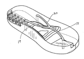
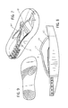
- FIG. 1 is a depiction of one embodiment of the sandal from a perspective view—the left sandal is shown.
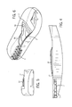
- FIG. 2 is a side view of one embodiment of the left sandal. The view is from the inside of the sandal, also known as the medial side, looking to the wearer's left.
- FIG. 3 is a top view of one embodiment of the left sandal. This view shows one embodiment of the medial split feature in cutaway.
- FIG. 4 is a side view of one embodiment of the left sandal. The view is from the inside, or medial side, of the sandal looking to the wearer's left. This view also shows the apertures for the strap attachment points in cutaway.
- FIG. 5 is a front view of one embodiment of the left sandal. The view is from the inside, or medial side, of the sandal looking to the wearer's left.
- FIG. 6 is a depiction of one embodiment of the left sandal from another perspective view. This view also shows the strap attachment apertures and medial split in cutaway view.
- FIG. 7 is a perspective view of the one embodiment of the left sandal that shows the strap.
- FIG. 8 is an additional perspective view of one embodiment of the left sandal that shows the strap.
- FIG. 9 is a view of one embodiment of the sole bottom that includes a swirl tread design.
- the sandal can be used for the treatment and prevention of plantar fasciitis.
- the sandal has sole 1 .
- Sole 1 will include big toe rise 6 , medial split 7 , upward bend 8 and metatarsal bar 9 . All the figures show that upward bend 8 and metatarsal bar 9 are contiguous, integrated components.
- sole 1 has rocker bottom 10 .
- the wearer When the wearer is in a neutral position, only the center of sole 1 will be in contact with the ground surface. The elevations in the front and back sections of rocker bottom 10 will be slightly off the floor.
- the sandal will have a shape that is generally in the broad outline of an anatomically correct foot.
- the anatomically correct foot includes slight medial angulation of the hind foot and slight adduction of the mid and forefoot.
- the overall design of the rocker bottom sole is designed to be sharp enough to decrease tension on the plantar fascia, but shallow enough to allow only gentle balance motions to promote massage of the fascia and strengthening of the intrinsic muscles of the foot as well as the dynamic stabilizing muscles of the ankle.
- Big toe rise 6 is designed so that the wearer's big toe is higher than the other toes. The wearer's other toes rest on lateral toe bed 11 which is lower than big toe rise 6 . Big toe rise 6 is sized so as to lift the wearer's big toe higher than the remaining toes. Big toe rise 6 begins approximately at metatarsophalangeal (MTP) joint point 24 of sole 1 . MTP joint point 24 approximately coincides with the wearer's first MTP joint of the big toe. In one preferred embodiment, big toe rise 6 will rise up from MTP joint point 24 going toward the front of sole 1 at an angle of approximately 5 to 20 degrees. As shown in FIGS.
- MTP metatarsophalangeal
- toe slope 12 will connect lateral toe bed 11 and big toe rise 6 to provide greater comfort for the wearer.
- big toe rise 6 begins just at the level of the sesamoid bones and provides a cushion for these bones.
- the angulation of the big toe rise will be approximately 15 to 20 degrees.
- toe rise 6 will promote the windlass mechanism of the plantar fascia.
- the windlass mechanism describes how the plantar fascia is pulled taut during the wearer's gait.
- the windlass mechanism is caused by the dorsiflexion of the first MTP joint during the phase of gait known as “toe-off.”
- the toe-off phase occurs as the body moves over the planted foot.
- the foot moves in a slightly rotational way, spinning from the fifth metatarsal head, along the ball of the foot, to the first MTP joint.
- the MTP joint flexes and the plantar fascia pulls taught.
- the heel is tipped into varus and the posterior tibial muscle fires.
- Plantar fasciitis is caused by an imbalance at any point of this complex relationship during the gait cycle. This problem is often exacerbated by those with varus hindfeet, stiff first MTP joints and neutral to cavus midfeet.
- the improved sandal is designed to accommodate the biomechanical forces that promote and exacerbate plantar fasciitis. By assisting in forward roll with a rocker-bottom, using tread design to accommodate the lateral to medial spin during gait, cushioning the origin of the plantar fascia with the medial split and assisting the windlass mechanism with the toe rise, the sandal described herein will allow for improvement in the symptoms of plantar fasciitis.
- the gait cycle begins with heel strike. Historically, it was thought that the hindfoot struck the ground in a position of eversion. However it is more likely that the heel strikes in slight varus and quickly moves to eversion as the foot moves to foot-flat during gait. Sole 1 has a slight lateral to medial curve with rises on each side and contact being more centralized at the heel. This shape of sole 1 will assist the wearer in this natural motion. As the heel strikes in varus, the lateral portion of the hindfoot sole will easily accommodate this force. As the heel moves to eversion the medial portion of the posterior sole will allow for lesser impact on the calcaneus and plantar fascia. Medial split 7 is limited to the posterior medial aspect of the heel in order to allow for enough support during gait.
- Medial split 7 allows for a slightly less amount of energy to be absorbed by the calcaneus in the region of the plantar fascia insertion. Often, in plantar fasciitis, this region of bone has stress changes consistent with “bone bruising.” Medial split 7 and the overall design of the sandal aim to lessen the pain associated with this type of bone bruising.
- Medial split 7 is a void or cut out section of sole 1 .
- the location of medial split is at the back of sole 1 , behind upward bend 8 and metatarsal bar 9 .
- Medial split 7 is designed so that when the wearer initially strikes heel 13 against the ground surface, the wearer's weight will be equally supported medially and laterally. However, as the wearer's weight on heel 13 is increased, medial split 7 will compress more than the lateral section of heel 13 . The compression effect will absorb energy from the medial portion of the heel while still providing some suspension for the medial heel strike. The purpose of this feature is to promote a lateral to medial rotation of the heel portion and reduce wearer heel pain.
- medial split takes up approximately 25% of the length of sole 1 and 50% of the width of sole 1 at heel 13 .
- medial split extends forward from heel 13 and terminates at the mid-arch section 15 of sole 1 . It is believed that medial split 7 can perform its desired functions described above if it takes between 20% and 30% of the length of sole 1 and 30% to 50% of the width of sole 1 .
- medial split 7 can be constructed by a void in sole 1 that is then partially filled by columns 11 .
- Material for columns 11 is chosen so that medial split 7 will compress more than the surrounding sections of sole 1 during the gait of the wearer.
- sole 11 is constructed of conventional materials used in sandal construction.
- the sole can be constructed in a single layer using ethylene vinyl acetate (EVA), polyurethane surrounding another material such as gel or liquid silicone, or polyurethane foam.
- EVA ethylene vinyl acetate
- sole 1 in layers, including but not limited to a top layer, midsole, and outsole. If layers are used, the insole is typically a thin layer of EVA.
- the midsole which is usually the thickest layer, consists of polyurethane surrounding another material such as gel or liquid silicone, or polyurethane foam.
- Outsoles are usually made of some type of rubber.
- medial split 7 is a void partially filled with columns
- medial split 7 could also be designed in other ways to create the same results during the wearer's gait.
- Medial split 7 could be a void only, in which case the material immediately adjacent the void would need to have greater density and flexion resistance so as to allow some compression but also some medial support through the wearer's heel strike and gait.
- Medial split 7 could also be constructed by using material that is less dense in this section of the sole.
- Medial split 7 could also be constructed by a void that is partially occupied by structures other than columns 11 .
- the void could be partially occupied by honeycomb structures or by parallel wall structures oriented in any direction.
- sole 11 can include a tread pattern with a ball and swirl design. This tread pattern will promote the lateral to medial spin of the wearer's foot during the gait. Those skilled in the art will be familiar with variations of the ball and swirl tread design that will perform the desired function.
- Metatarsal bar 9 serves to support the transverse arch.
- the transverse arch of the foot is the arch that runs along the mediolateral axis of the foot. As shown in FIG. 5 , bar mid-section 16 is higher than bar lateral section 17 . As the upwardly curved shape of metatarsal bar 9 supports the transverse arch, it is believed that this shape will help to prevent collapse of the middle foot as the windlass mechanism is activated.
- the medial longitudinal arch that is usually associated with the concept of ‘arch’ in the foot, is also supported in terms of function by the transverse arch.
- the transverse arch is formed at the bony level by the association of the cuneiforms as they articulate with the metatarsals.
- the apex of this arch is at the position of the 2nd metatarsal bone. If the transverse arch is accommodated and there is less stress on the keystone position of this arch, there is less stress on the medial longitudinal arch.
- the improved sandal with its strong structural transverse arch, will reduce the force required by the posterior tibial muscle, the main dynamic stabilizer of the foot. Therefore, most of this muscle and tendon unit's force will go toward stabilizing the apex of the medial longitudinal arch.
- metatarsal bar 9 is partially integrated with gently sloped upward bend 8 .
- Upward bend 8 begins to rise from sole 1 at a point just forward of the terminus of medial split 7 and reaches its highest point at its intersection with metatarsal bar 9 .
- Upward bend 8 then slopes downward again, terminating at sole 1 at a point slightly behind big toe rise 6 .
- Upward bend 8 also serves to support the arch during the activation of the windlass mechanism.
- the sandal will include strap 2 .
- Strap 2 includes strap junction 17 , anterior segment 18 , medial segment 19 , and lateral segment 20 .
- Anterior segment 18 extends from strap junction 17 to anterior attachment point 21 .
- anterior attachment point 21 is located on sole 1 at a point in or proximate to big toe rise 6 .
- Medial segment 19 extends from strap junction 21 to medial attachment point 22 .
- medial attachment point 22 is located on sole 1 at a point in or immediately forward of medial split 7 .
- medial section 19 originates from the front edge of medial split 7 .
- Lateral segment 20 extends from strap junction 21 to lateral attachment point 23 .
- lateral attachment point 23 is located on sole 1 at a point near the medial edge of sole 1 but at a point on the long axis of sole 1 that is approximately even with medial attachment point 22 .
- strap 17 is constructed so that its segments have varying densities. Specifically, the density and stiffness of medial segment 19 and lateral segment 20 are greater than the density and stiffness for strap junction 17 and anterior segment 18 . It is believed that having relatively greater stiffness and density in medial segment 19 and lateral segment 20 will keep metatarsal bar 9 and upward bend 8 engaged with the transverse arch of the wearer during the wearer's gait.
- the combination of the elements will provide therapeutic effects for those wearers who suffer from plantar fasciitis and preventative effects for those who do not.
- the rocker sole 10 with a gentle medial to lateral rise also present in the hindfoot again allows for reduced tension on the tie-rod or the medial longitudinal arch, or plantar fascia, during gait.
- the improved sandal provides a biomechanical assistive portion at each moment designed to reduce the stress on the plantar fascia and yet allow efficient gait. It is believed that the combination of all of these biomechanical elements in this design will allow for a reduction in plantar fascia pain for those suffering this debilitating disease.
- the treatment of plantar fasciitis by this improved sandal a far more cost effective treatment for this problem than any invasive treatments now available.
Landscapes
- Health & Medical Sciences (AREA)
- Epidemiology (AREA)
- General Health & Medical Sciences (AREA)
- Public Health (AREA)
- Footwear And Its Accessory, Manufacturing Method And Apparatuses (AREA)
Abstract
Description
- This application claims priority to the U.S. patent application Ser. No. 13/103,746 titled “SANDAL” filed on May 9, 2011.
- Not Applicable.
- Not Applicable.
-
FIG. 1 is a depiction of one embodiment of the sandal from a perspective view—the left sandal is shown. -
FIG. 2 is a side view of one embodiment of the left sandal. The view is from the inside of the sandal, also known as the medial side, looking to the wearer's left. -
FIG. 3 is a top view of one embodiment of the left sandal. This view shows one embodiment of the medial split feature in cutaway. -
FIG. 4 is a side view of one embodiment of the left sandal. The view is from the inside, or medial side, of the sandal looking to the wearer's left. This view also shows the apertures for the strap attachment points in cutaway. -
FIG. 5 is a front view of one embodiment of the left sandal. The view is from the inside, or medial side, of the sandal looking to the wearer's left. -
FIG. 6 is a depiction of one embodiment of the left sandal from another perspective view. This view also shows the strap attachment apertures and medial split in cutaway view. -
FIG. 7 is a perspective view of the one embodiment of the left sandal that shows the strap. -
FIG. 8 is an additional perspective view of one embodiment of the left sandal that shows the strap. -
FIG. 9 is a view of one embodiment of the sole bottom that includes a swirl tread design. - An improved sandal with several orthotic benefits is described herein. It is believed that the sandal can be used for the treatment and prevention of plantar fasciitis. As depicted in
FIG. 1 , the sandal has sole 1. Sole 1 will include big toe rise 6,medial split 7, upwardbend 8 andmetatarsal bar 9. All the figures show that upwardbend 8 andmetatarsal bar 9 are contiguous, integrated components. - As shown in
FIG. 2 ,sole 1 hasrocker bottom 10. When the wearer is in a neutral position, only the center of sole 1 will be in contact with the ground surface. The elevations in the front and back sections ofrocker bottom 10 will be slightly off the floor. As shown inFIG. 3 , the sandal will have a shape that is generally in the broad outline of an anatomically correct foot. The anatomically correct foot includes slight medial angulation of the hind foot and slight adduction of the mid and forefoot. The overall design of the rocker bottom sole is designed to be sharp enough to decrease tension on the plantar fascia, but shallow enough to allow only gentle balance motions to promote massage of the fascia and strengthening of the intrinsic muscles of the foot as well as the dynamic stabilizing muscles of the ankle. - Big toe rise 6 is designed so that the wearer's big toe is higher than the other toes. The wearer's other toes rest on
lateral toe bed 11 which is lower than big toe rise 6. Big toe rise 6 is sized so as to lift the wearer's big toe higher than the remaining toes. Big toe rise 6 begins approximately at metatarsophalangeal (MTP)joint point 24 of sole 1.MTP joint point 24 approximately coincides with the wearer's first MTP joint of the big toe. In one preferred embodiment, big toe rise 6 will rise up fromMTP joint point 24 going toward the front of sole 1 at an angle of approximately 5 to 20 degrees. As shown inFIGS. 1 and 3 , in one preferred embodiment,toe slope 12 will connectlateral toe bed 11 and big toe rise 6 to provide greater comfort for the wearer. In an additional preferred embodiment, big toe rise 6 begins just at the level of the sesamoid bones and provides a cushion for these bones. In an additional preferred embodiment the angulation of the big toe rise will be approximately 15 to 20 degrees. - It is believed that toe rise 6 will promote the windlass mechanism of the plantar fascia. The windlass mechanism describes how the plantar fascia is pulled taut during the wearer's gait. The windlass mechanism is caused by the dorsiflexion of the first MTP joint during the phase of gait known as “toe-off.” The toe-off phase occurs as the body moves over the planted foot. The foot moves in a slightly rotational way, spinning from the fifth metatarsal head, along the ball of the foot, to the first MTP joint. At that point in the gait cycle, the MTP joint flexes and the plantar fascia pulls taught. The heel is tipped into varus and the posterior tibial muscle fires. This initiates heel rise, then the achilles mechanism allows for push-off. Plantar fasciitis is caused by an imbalance at any point of this complex relationship during the gait cycle. This problem is often exacerbated by those with varus hindfeet, stiff first MTP joints and neutral to cavus midfeet. The improved sandal is designed to accommodate the biomechanical forces that promote and exacerbate plantar fasciitis. By assisting in forward roll with a rocker-bottom, using tread design to accommodate the lateral to medial spin during gait, cushioning the origin of the plantar fascia with the medial split and assisting the windlass mechanism with the toe rise, the sandal described herein will allow for improvement in the symptoms of plantar fasciitis.
- The gait cycle begins with heel strike. Historically, it was thought that the hindfoot struck the ground in a position of eversion. However it is more likely that the heel strikes in slight varus and quickly moves to eversion as the foot moves to foot-flat during gait. Sole 1 has a slight lateral to medial curve with rises on each side and contact being more centralized at the heel. This shape of sole 1 will assist the wearer in this natural motion. As the heel strikes in varus, the lateral portion of the hindfoot sole will easily accommodate this force. As the heel moves to eversion the medial portion of the posterior sole will allow for lesser impact on the calcaneus and plantar fascia.
Medial split 7 is limited to the posterior medial aspect of the heel in order to allow for enough support during gait.Medial split 7 allows for a slightly less amount of energy to be absorbed by the calcaneus in the region of the plantar fascia insertion. Often, in plantar fasciitis, this region of bone has stress changes consistent with “bone bruising.”Medial split 7 and the overall design of the sandal aim to lessen the pain associated with this type of bone bruising. - With reference to all the figures,
medial split 7 will now be described in greater detail.Medial split 7 is a void or cut out section of sole 1. The location of medial split is at the back of sole 1, behindupward bend 8 andmetatarsal bar 9.Medial split 7 is designed so that when the wearer initially strikesheel 13 against the ground surface, the wearer's weight will be equally supported medially and laterally. However, as the wearer's weight onheel 13 is increased,medial split 7 will compress more than the lateral section ofheel 13. The compression effect will absorb energy from the medial portion of the heel while still providing some suspension for the medial heel strike. The purpose of this feature is to promote a lateral to medial rotation of the heel portion and reduce wearer heel pain. - In the embodiment shown, medial split takes up approximately 25% of the length of sole 1 and 50% of the width of sole 1 at
heel 13. In a preferred embodiment, medial split extends forward fromheel 13 and terminates at themid-arch section 15 of sole 1. It is believed thatmedial split 7 can perform its desired functions described above if it takes between 20% and 30% of the length of sole 1 and 30% to 50% of the width of sole 1. - All the figures except
FIG. 5 show that in one embodiment,medial split 7 can be constructed by a void in sole 1 that is then partially filled bycolumns 11. Material forcolumns 11 is chosen so thatmedial split 7 will compress more than the surrounding sections of sole 1 during the gait of the wearer. - The remainder of sole 11 is constructed of conventional materials used in sandal construction. Those skilled in the art will know that the sole can be constructed in a single layer using ethylene vinyl acetate (EVA), polyurethane surrounding another material such as gel or liquid silicone, or polyurethane foam. In some cases, those skilled can construct sole 1 in layers, including but not limited to a top layer, midsole, and outsole. If layers are used, the insole is typically a thin layer of EVA. The midsole, which is usually the thickest layer, consists of polyurethane surrounding another material such as gel or liquid silicone, or polyurethane foam. Outsoles are usually made of some type of rubber. Those skilled in the art may also choose to use cork or wood as materials, or any material which may be fashioned using injection molding or three-dimensional sculpting with Computer Aided Design (CAD) devices. It will be obvious to those skilled in the art to use a variety of such materials for the sole 1, and this invention is not intended to be limited to any particular materials used in sole 1.
- While in the embodiment depicted,
medial split 7 is a void partially filled with columns,medial split 7 could also be designed in other ways to create the same results during the wearer's gait.Medial split 7 could be a void only, in which case the material immediately adjacent the void would need to have greater density and flexion resistance so as to allow some compression but also some medial support through the wearer's heel strike and gait.Medial split 7 could also be constructed by using material that is less dense in this section of the sole.Medial split 7 could also be constructed by a void that is partially occupied by structures other thancolumns 11. For example, the void could be partially occupied by honeycomb structures or by parallel wall structures oriented in any direction. - As shown in the embodiment in
FIG. 9 , sole 11 can include a tread pattern with a ball and swirl design. This tread pattern will promote the lateral to medial spin of the wearer's foot during the gait. Those skilled in the art will be familiar with variations of the ball and swirl tread design that will perform the desired function. -
Metatarsal bar 9 serves to support the transverse arch. The transverse arch of the foot is the arch that runs along the mediolateral axis of the foot. As shown inFIG. 5 ,bar mid-section 16 is higher thanbar lateral section 17. As the upwardly curved shape ofmetatarsal bar 9 supports the transverse arch, it is believed that this shape will help to prevent collapse of the middle foot as the windlass mechanism is activated. - The medial longitudinal arch, that is usually associated with the concept of ‘arch’ in the foot, is also supported in terms of function by the transverse arch. The transverse arch is formed at the bony level by the association of the cuneiforms as they articulate with the metatarsals. The apex of this arch is at the position of the 2nd metatarsal bone. If the transverse arch is accommodated and there is less stress on the keystone position of this arch, there is less stress on the medial longitudinal arch. The improved sandal, with its strong structural transverse arch, will reduce the force required by the posterior tibial muscle, the main dynamic stabilizer of the foot. Therefore, most of this muscle and tendon unit's force will go toward stabilizing the apex of the medial longitudinal arch. This reduces the stress on either end of the tie-rod of that arch. Arches have forces at each inferior point with compression of the apex of the arch. The vector of force is typically away from these points as the apex depresses with load. A tie-rod connects the two bottom points of the arch. As the arch depresses, and therefore widens, these ends of the tie-rod must handle the tension applied. In the foot, the ends of the tie-rod at the origin of the plantar fascia and the first metatarsophlangeal joint. The improved sandal design will promote a reduction in the tension applied at the point of origin of the plantar fascia and thereby decrease pain.
- As shown in the figures,
metatarsal bar 9 is partially integrated with gently slopedupward bend 8.Upward bend 8 begins to rise from sole 1 at a point just forward of the terminus ofmedial split 7 and reaches its highest point at its intersection withmetatarsal bar 9.Upward bend 8 then slopes downward again, terminating at sole 1 at a point slightly behind big toe rise 6.Upward bend 8 also serves to support the arch during the activation of the windlass mechanism. - As shown in
FIGS. 5, 7, and 8 , the sandal will include strap 2. Strap 2 includesstrap junction 17,anterior segment 18,medial segment 19, andlateral segment 20.Anterior segment 18 extends fromstrap junction 17 toanterior attachment point 21. Preferablyanterior attachment point 21 is located on sole 1 at a point in or proximate to big toe rise 6.Medial segment 19 extends fromstrap junction 21 tomedial attachment point 22. Preferablymedial attachment point 22 is located on sole 1 at a point in or immediately forward ofmedial split 7. In one preferred embodiment,medial section 19 originates from the front edge ofmedial split 7.Lateral segment 20 extends fromstrap junction 21 tolateral attachment point 23. Preferablylateral attachment point 23 is located on sole 1 at a point near the medial edge of sole 1 but at a point on the long axis of sole 1 that is approximately even withmedial attachment point 22. - In one preferred embodiment,
strap 17 is constructed so that its segments have varying densities. Specifically, the density and stiffness ofmedial segment 19 andlateral segment 20 are greater than the density and stiffness forstrap junction 17 andanterior segment 18. It is believed that having relatively greater stiffness and density inmedial segment 19 andlateral segment 20 will keepmetatarsal bar 9 andupward bend 8 engaged with the transverse arch of the wearer during the wearer's gait. - The combination of the elements will provide therapeutic effects for those wearers who suffer from plantar fasciitis and preventative effects for those who do not. The rocker sole 10 with a gentle medial to lateral rise also present in the hindfoot again allows for reduced tension on the tie-rod or the medial longitudinal arch, or plantar fascia, during gait. As the foot moves from heel-strike to foot-flat to toe-off, the improved sandal provides a biomechanical assistive portion at each moment designed to reduce the stress on the plantar fascia and yet allow efficient gait. It is believed that the combination of all of these biomechanical elements in this design will allow for a reduction in plantar fascia pain for those suffering this debilitating disease. The treatment of plantar fasciitis by this improved sandal a far more cost effective treatment for this problem than any invasive treatments now available.
- Any and all references to patents, documents, and other writings contained herein shall not be construed as an admission as to their status with respect to being or not being prior art.
- The described features, advantages, and characteristics may be combined in any suitable manner in one or more embodiments. One skilled in the relevant art will recognize that the various components of this design may be practiced without one or more of the specific features or advantages of a particular embodiment. In other instances, additional features and advantages may be recognized in certain embodiments that may not be present in all embodiments.
- Reference throughout this specification to “one embodiment”, “an embodiment”, or similar language means that a particular feature, structure, or characteristic described in connection with the embodiment is included in at least one embodiment. Thus the appearance of the phrase “in one embodiment”, “in an embodiment”, and similar language throughout this specification may, but do not necessarily, all refer to the same embodiment.
- The invention may be embodied in other specific forms without departing from the spirit or essential characteristics thereof. The present embodiments are therefore considered in all respects as illustrative and not restrictive. Accordingly, the scope of the invention is established by the appended claims rather than the foregoing description. All changes which come within the meaning and range of equivalency of the claims are therefore intended to be embraced therein.
- Moreover, the terms “substantially” or “approximately” as used herein may be applied to modify any quantitative representation that could permissibly vary without resulting in a change to the basic function to which it is related.
-
- sole 1
- strap 2
- front strap 3
- medial strap 4
- lateral strap 5
- big toe rise 6
-
medial split 7 -
upward bend 8 -
metatarsal bar 9 -
rocker bottom 10 -
lateral toe bed 11 -
toe slope 12 -
heel 13 - columns 14
-
mid-arch section 15 -
bar midsection 16 -
strap junction 17 -
anterior segment 18 -
medial segment 19 -
lateral segment 20 - anterior attachment point
-
medial attachment point 22 -
lateral attachment point 23 - MTP
joint point 24
Claims (11)
Priority Applications (2)
| Application Number | Priority Date | Filing Date | Title |
|---|---|---|---|
| US15/839,931 US10757997B2 (en) | 2011-05-09 | 2017-12-13 | Sandal |
| US16/987,540 US11744317B2 (en) | 2011-05-09 | 2020-08-07 | Sandal with heel strap |
Applications Claiming Priority (2)
| Application Number | Priority Date | Filing Date | Title |
|---|---|---|---|
| US13/103,746 US9867419B1 (en) | 2011-05-09 | 2011-05-09 | Sandal |
| US15/839,931 US10757997B2 (en) | 2011-05-09 | 2017-12-13 | Sandal |
Related Parent Applications (1)
| Application Number | Title | Priority Date | Filing Date |
|---|---|---|---|
| US13/103,746 Continuation US9867419B1 (en) | 2011-05-09 | 2011-05-09 | Sandal |
Related Child Applications (1)
| Application Number | Title | Priority Date | Filing Date |
|---|---|---|---|
| US16/987,540 Continuation-In-Part US11744317B2 (en) | 2011-05-09 | 2020-08-07 | Sandal with heel strap |
Publications (2)
| Publication Number | Publication Date |
|---|---|
| US20180098598A1 true US20180098598A1 (en) | 2018-04-12 |
| US10757997B2 US10757997B2 (en) | 2020-09-01 |
Family
ID=60935483
Family Applications (2)
| Application Number | Title | Priority Date | Filing Date |
|---|---|---|---|
| US13/103,746 Active 2034-08-05 US9867419B1 (en) | 2011-05-09 | 2011-05-09 | Sandal |
| US15/839,931 Active 2031-09-15 US10757997B2 (en) | 2011-05-09 | 2017-12-13 | Sandal |
Family Applications Before (1)
| Application Number | Title | Priority Date | Filing Date |
|---|---|---|---|
| US13/103,746 Active 2034-08-05 US9867419B1 (en) | 2011-05-09 | 2011-05-09 | Sandal |
Country Status (1)
| Country | Link |
|---|---|
| US (2) | US9867419B1 (en) |
Cited By (3)
| Publication number | Priority date | Publication date | Assignee | Title |
|---|---|---|---|---|
| US20180338854A1 (en) * | 2017-05-25 | 2018-11-29 | Cluffy Biomedical, LLC | Reverse insole |
| WO2025146773A1 (en) * | 2024-01-04 | 2025-07-10 | 哲也 伊藤 | Footwear |
| WO2025182382A1 (en) * | 2024-02-27 | 2025-09-04 | 哲也 伊藤 | Footwear |
Families Citing this family (2)
| Publication number | Priority date | Publication date | Assignee | Title |
|---|---|---|---|---|
| ES2732234A1 (en) * | 2018-05-20 | 2019-11-21 | Carrillo Sanchez Arturo | Polarized Flip Flops (Machine-translation by Google Translate, not legally binding) |
| US12471662B2 (en) * | 2022-04-14 | 2025-11-18 | Bass Pro Intellectual Property, L.L.C. | Footwear with cork outsole |
Citations (4)
| Publication number | Priority date | Publication date | Assignee | Title |
|---|---|---|---|---|
| US4419836A (en) * | 1978-06-19 | 1983-12-13 | Wong James K | Footwear in the form of a sandal |
| US5579591A (en) * | 1993-06-29 | 1996-12-03 | Limited Responsibility Company Frontier | Footwear for patients of osteoarthritis of the knee |
| US6170176B1 (en) * | 1999-12-21 | 2001-01-09 | James G. Clough | Shoe apparatus and method |
| US7832119B2 (en) * | 2006-02-17 | 2010-11-16 | Solution Source | First metatarsal head lift orthotic |
Family Cites Families (3)
| Publication number | Priority date | Publication date | Assignee | Title |
|---|---|---|---|---|
| US4262433A (en) * | 1978-08-08 | 1981-04-21 | Hagg Vernon A | Sole body for footwear |
| BE885449A (en) * | 1980-09-29 | 1981-01-16 | Spronken Orthopedie | OUTSOLE FOR USE UNDER AN IMMOBILIZING LIBRARY WITH ALL FOOT JOINTS STIFF |
| US6983555B2 (en) * | 2003-03-24 | 2006-01-10 | Reebok International Ltd. | Stable footwear that accommodates shear forces |
-
2011
- 2011-05-09 US US13/103,746 patent/US9867419B1/en active Active
-
2017
- 2017-12-13 US US15/839,931 patent/US10757997B2/en active Active
Patent Citations (4)
| Publication number | Priority date | Publication date | Assignee | Title |
|---|---|---|---|---|
| US4419836A (en) * | 1978-06-19 | 1983-12-13 | Wong James K | Footwear in the form of a sandal |
| US5579591A (en) * | 1993-06-29 | 1996-12-03 | Limited Responsibility Company Frontier | Footwear for patients of osteoarthritis of the knee |
| US6170176B1 (en) * | 1999-12-21 | 2001-01-09 | James G. Clough | Shoe apparatus and method |
| US7832119B2 (en) * | 2006-02-17 | 2010-11-16 | Solution Source | First metatarsal head lift orthotic |
Cited By (4)
| Publication number | Priority date | Publication date | Assignee | Title |
|---|---|---|---|---|
| US20180338854A1 (en) * | 2017-05-25 | 2018-11-29 | Cluffy Biomedical, LLC | Reverse insole |
| US11020263B2 (en) * | 2017-05-25 | 2021-06-01 | Cluffy, LLC | Reverse insole |
| WO2025146773A1 (en) * | 2024-01-04 | 2025-07-10 | 哲也 伊藤 | Footwear |
| WO2025182382A1 (en) * | 2024-02-27 | 2025-09-04 | 哲也 伊藤 | Footwear |
Also Published As
| Publication number | Publication date |
|---|---|
| US10757997B2 (en) | 2020-09-01 |
| US9867419B1 (en) | 2018-01-16 |
Similar Documents
| Publication | Publication Date | Title |
|---|---|---|
| US10757997B2 (en) | Sandal | |
| RU2489069C2 (en) | Sole for low shoe, in particular - training shoe | |
| US8250784B2 (en) | Shoe insole | |
| US5826351A (en) | Shoe sole and shoe and sandal including the sole | |
| US9167864B1 (en) | Footwear with dynamic arch system | |
| KR102463611B1 (en) | insoles for shoes | |
| US10314363B2 (en) | Insole for shoe | |
| JP2015526251A (en) | Basketball insole | |
| JPWO2020136916A1 (en) | Sole and shoes | |
| KR101514680B1 (en) | Mesopodium and Of metatarsal and to distribute the pressure of Midsole and Shoes this fulfill | |
| US10827798B2 (en) | Footwear with dynamic arch system | |
| JP5729558B2 (en) | Insoles | |
| US9918515B2 (en) | Footwear with dynamic arch system | |
| KR20140069009A (en) | Shoe and method for the construction thereof | |
| WO1999020134A1 (en) | Footwear having a protuberance | |
| JP7500024B2 (en) | Shoe sole with shock absorbing layer structure | |
| US11452329B2 (en) | Orthopedic shoe appliance | |
| US20110289802A1 (en) | Shoe appliance with an orthopedic device | |
| US11744317B2 (en) | Sandal with heel strap | |
| JP5970423B2 (en) | Foot pads | |
| JP7397259B2 (en) | Corrective socks and foot orthopedic supports | |
| JP7285990B1 (en) | insole | |
| JP7350346B2 (en) | footwear | |
| WO2026053385A1 (en) | Insole | |
| KR101397429B1 (en) | Posture correcting functioanal shoes |
Legal Events
| Date | Code | Title | Description |
|---|---|---|---|
| FEPP | Fee payment procedure |
Free format text: ENTITY STATUS SET TO UNDISCOUNTED (ORIGINAL EVENT CODE: BIG.); ENTITY STATUS OF PATENT OWNER: SMALL ENTITY |
|
| FEPP | Fee payment procedure |
Free format text: ENTITY STATUS SET TO SMALL (ORIGINAL EVENT CODE: SMAL); ENTITY STATUS OF PATENT OWNER: SMALL ENTITY |
|
| STPP | Information on status: patent application and granting procedure in general |
Free format text: DOCKETED NEW CASE - READY FOR EXAMINATION |
|
| STPP | Information on status: patent application and granting procedure in general |
Free format text: NON FINAL ACTION MAILED |
|
| STPP | Information on status: patent application and granting procedure in general |
Free format text: NOTICE OF ALLOWANCE MAILED -- APPLICATION RECEIVED IN OFFICE OF PUBLICATIONS |
|
| STCF | Information on status: patent grant |
Free format text: PATENTED CASE |
|
| MAFP | Maintenance fee payment |
Free format text: PAYMENT OF MAINTENANCE FEE, 4TH YR, SMALL ENTITY (ORIGINAL EVENT CODE: M2551); ENTITY STATUS OF PATENT OWNER: SMALL ENTITY Year of fee payment: 4 |