US20180098550A1 - Safety system - Google Patents
Safety system Download PDFInfo
- Publication number
- US20180098550A1 US20180098550A1 US15/363,544 US201615363544A US2018098550A1 US 20180098550 A1 US20180098550 A1 US 20180098550A1 US 201615363544 A US201615363544 A US 201615363544A US 2018098550 A1 US2018098550 A1 US 2018098550A1
- Authority
- US
- United States
- Prior art keywords
- processing unit
- safety
- signal
- glove
- conducting element
- Prior art date
- Legal status (The legal status is an assumption and is not a legal conclusion. Google has not performed a legal analysis and makes no representation as to the accuracy of the status listed.)
- Granted
Links
Images


Classifications
-
- A—HUMAN NECESSITIES
- A22—BUTCHERING; MEAT TREATMENT; PROCESSING POULTRY OR FISH
- A22B—SLAUGHTERING
- A22B5/00—Accessories for use during or after slaughtering
- A22B5/16—Skinning instruments or knives
- A22B5/166—Drum skinners
-
- F—MECHANICAL ENGINEERING; LIGHTING; HEATING; WEAPONS; BLASTING
- F16—ENGINEERING ELEMENTS AND UNITS; GENERAL MEASURES FOR PRODUCING AND MAINTAINING EFFECTIVE FUNCTIONING OF MACHINES OR INSTALLATIONS; THERMAL INSULATION IN GENERAL
- F16P—SAFETY DEVICES IN GENERAL; SAFETY DEVICES FOR PRESSES
- F16P3/00—Safety devices acting in conjunction with the control or operation of a machine; Control arrangements requiring the simultaneous use of two or more parts of the body
- F16P3/12—Safety devices acting in conjunction with the control or operation of a machine; Control arrangements requiring the simultaneous use of two or more parts of the body with means, e.g. feelers, which in case of the presence of a body part of a person in or near the danger zone influence the control or operation of the machine
- F16P3/14—Safety devices acting in conjunction with the control or operation of a machine; Control arrangements requiring the simultaneous use of two or more parts of the body with means, e.g. feelers, which in case of the presence of a body part of a person in or near the danger zone influence the control or operation of the machine the means being photocells or other devices sensitive without mechanical contact
- F16P3/147—Safety devices acting in conjunction with the control or operation of a machine; Control arrangements requiring the simultaneous use of two or more parts of the body with means, e.g. feelers, which in case of the presence of a body part of a person in or near the danger zone influence the control or operation of the machine the means being photocells or other devices sensitive without mechanical contact using electro-magnetic technology, e.g. tags or radar
Definitions
- the present invention relates to a safety system for work machines provided for protecting operators.
- the system can be applied to any type of machinery that has at least one moving organ with which an operator can come into contact accidentally.
- a known skinner comprises a frame that supports a plane on which the portion of meat to be skinned is placed.
- the machine is equipped with a toothed roller, put in rotation by a motor, which drags the portion of meat, manually retained by the operator, to subject it to the action of a blade, in order to remove its rind.
- skinners may be equipped with electronic safety systems.
- a safety system which comprises an electronic unit associated with the operator and a central processing unit associated with the operating machine, able to receive signals from the unit associated with the operator.
- the unit associated with the operator is connected to gloves entirely made of a conductive material, envisaged to be worn by an operator.
- the central unit is configured to block the machine if the glove comes into contact with the roll or the blade, in turn made of conductive material.
- the drawbacks encountered in the known system include in particular the fact that it does not provide the certainty that the skinner is only and exclusively activated if the operator is actually wearing both gloves.
- the technical task underlying the present invention is therefore to propose an electronic safety system that is more effective than the known systems mentioned above.
- the technical task is reached by the safety system provided in accordance with claim 1 .
- FIG. 1 is a representation, projected onto a plane, of the path of a safety wire applied to a glove according to the invention
- FIG. 2 is a schematic axonometric view of a glove according to the invention.
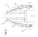
- FIG. 3 is a schematic front view of a sling according to the invention, worn by an operator;
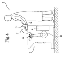
- FIG. 4 is a schematic lateral view of an operator wearing a work uniform on top of the sling according to the previous figure and using a skinner;
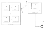
- FIG. 5 is a diagram that represents the proposed system
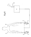
- FIG. 6 is a diagram that represents some aspects of a particular embodiment of the invention.
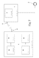
- FIG. 7 is a diagram that represents the first and the second electronic processing unit according to the invention.
- 1 indicates a safety system according to the invention.
- the proposed system 1 has been devised for use with an industrial machine 2 equipped with a moving organ 21 , especially a machine for processing meat or fish on an industrial scale.
- the invention has been designed for use with a skinner 2 , of the type described in the discussion of the known art.
- the mentioned moving organ comprises the toothed roller 21 , mentioned above.
- the proposed system 1 is designed to protect the safety of operators 3 working with the machine 21 , with particular reference to the integrity of their hands.
- the invention includes a first processing unit 4 associated with the toothed roller 21 and configured to receive signals.
- Such first processing unit 4 includes a command module 41 configured to modify the operation of the roller 21 , upon receiving an alarm signal.
- the command module 41 can establish the stopping of the roller 21 or the inversion of its rotation direction.
- the roller 21 can be activated by a motor 22 (shown in FIGS. 4 and 5 ) provided with a command logic configured to receive a stopping or inversion signal produced by the command module 41 .
- the command logic may comprise a control board that commands the remote control switches 23 activating the motor 22 based on signals for stopping or inverting the motion produced by the command module 41 of the first processing unit 4 .
- the invention includes gloves 5 that can be worn by an operator 3 during the operations for separating the rind, through the use of the skinner 2 .
- the operator 3 has available at least one pair of gloves 5 , right and left, which constitute components to allow the invention to detect a condition of serious danger to the integrity of the hands.
- a multitude of gloves 5 is made available, provided in accordance with the invention, to allow their replacement, when they are worn or damaged.
- the proposed system 1 also includes a second processing unit 6 , operatively associated with gloves 5 and configured to transmit signals to the first processing unit 4 .
- the second unit 6 is comprised in a second functional group which is worn by the operator 3 , while the first unit 4 can be included in a first functional group 40 , distinct from the second one and contained or integrated into the machine 2 .
- a first “fixed” functional group 40 may be provided for each machine 2 or there may also be a single central unit that remotely handles a plurality of skinners.
- the principle does not exclude the fact that the first and the second functional units 40 are contained in the same device or that they are even integrated or coinciding with each other.
- processing units 4 , 6 are presented hereunder as divided into distinct functional modules for the purpose of describing the functions thereof in a clear and complete manner.
- each processing unit may 4 , 6 consist of a single electronic device, duly programmed to perform the functions described, and the various modules may correspond to hardware and/or routine software entities belonging to the programmed device.
- Such functions may be performed by a plurality of electronic devices over which the aforesaid functional modules can be distributed.
- the first and second processing unit 4 , 6 each include a respective microcontroller.
- each glove 5 comprises an element 51 for conducting signals, connected to the second unit 6 and through at least one portion of the palm and/or the fingers and/or the edge of the hand.
- each glove 5 includes a single conducting element 51 which travels along the palm, the volar part of the fingers, including the “tips” (the parts that cover the fingertips) and the “edge” zone of the hand, opposite the thumb, including the external side of the little finger.
- the conducting element 51 substantially affects the whole of the front zone of the glove 5 , i.e. the one opposite the back, plus the lateral portion opposite the thumb.
- the conducting element 51 is preferably located at the surface of the glove 5 , but versions are also possible in which it is internal or incorporated into the fabric or material with which the glove 5 itself is made.
- the conducting element 51 may be wire-shaped and be sewn into the glove 5 itself.
- the conducting element 51 may define a path formed by rectilinear portions and curved portions, configured so that two contiguous portions are less than 10 mm away from each other and preferably less than 7 mm and, even more preferably about 5 mm away from each other; versions are not excluded in which two contiguous portions are less than 5 mm or 4 mm away from each other.
- the path, or circuit, described by the conducting element 51 is preferably composed of groups formed by a plurality of rectilinear portions connected by curved portions.
- five groups of the type described in the previous paragraph can be found, arranged in a succession along the path, and corresponding to: thumb, index finger, middle finger, ring finger, palm and little finger, together with the edge side of the hand.
- the conducting element 51 may be wire-shaped, and may be an electric wire, therefore adapted to transmit an electric safety signal, or an optical fibre, adapted to transmit an optical safety signal.
- the invention also includes a device for generating a safety signal connected to the conducting element 51 .
- the conducting element 51 is an electric wire which, for the purpose of simplicity, will be called the safety wire.
- the safety wire 51 may comprise a steel core coated in a teflon sheath and may be sewn onto the surface of the glove 5 with a sealing wire made of polyester or a synthetic material; applications are not excluded in which the sealing wire is made of natural material.
- the sheath of the safety wire 51 may be made of material other than teflon, however teflon is preferable as it allows protection from the acidic substances with which the safety wire 51 comes into contact while processing the meat, and also from ultraviolet rays.
- the glove 5 intended to cover the hand and to support the safety wire 51 is preferably made of cotton, so as to be easily tearable; in this way, in case of contact with the teeth of the roller 21 or with the edge of the blade, it is less likely for the glove 5 to get stuck and drag the hand against the roller 21 and the blade themselves.
- Special connection points may be provided, for example two conducting studs 52 located in opposite points of the glove 5 , to which respective opposite ends of the safety wire 51 are electrically connected.
- the device for generating the safety signal is placed in connection with the studs 52 through special terminals, so as to allow the closure of the circuit.
- a sort of sling 61 may be provided to be worn by the operator 3 , configured like a pouch, which carries fixed, or however integral, the aforementioned second functional group, from which pairs of cables 62 extend which end in respective terminals for connection with the studs 52 .
- the second functional group comprises the second processing unit 6 and the signal generating device, connected to one another and, for example, closed in a sealed way into the same casing.
- the second processing unit 6 comprises a first control module 63 configured to detect an interruption in the transmission of the safety signal along the safety wire 51 (or other conducting element) of at least one glove 5 .
- the invention may envisage a device for measuring the impedance of the signal that crosses the safety wire 51 connected to the second processing unit 6 ; such measurement device is preferably included in the second aforementioned functional group.
- the first control module 63 is configured to determine the interruption of the transmission of the signal following a measurement of the impedance value that reaches or exceeds an interruption threshold.
- the signal has been interrupted if the impedance measured in the safety wire 52 has an infinite value.
- the system 1 also envisages the second processing unit 6 comprising an alarm module 64 , subjected to the first control module 63 and able to generate an alarm signal, upon verifying the aforementioned interruption of the safety signal.
- the alarm signal is transmitted to the first processing unit 4 which then stops or inverts the motion of the roller 21 , according to the methods described above.
- the path of the safety wire 51 defines a particularly dense pattern at the zones of the glove 5 (and the hand) which are statistically more susceptible to being affected by contact with the roller 21 , it is clear that the invention allows possible accidents of operators to be strongly reduced, with a minimum or zero risk of false positives or negatives.
- the invention preferably comprises wireless telecommunication means 81 , 82 which connect the first and the second functional group.
- the second portable functional group may comprise a radio frequency transmitting device 81 , connected to the second unit 6 , able to transmit radio signals, in particular the mentioned alarm signal, to a receiver 82 connected to the first unit 4 and contained in the first functional group 40 (see the diagram in FIG. 5 ).
- each skinner 2 present in an industrial system for treating meat may be provided with its own first functional group 40 , to which the motor 22 of the toothed roller 21 is subjected, while each operator 3 can be equipped with the aforementioned sling 61 that carries the second functional group, able to detect and process the safety signals that run through the gloves 5 .
- the operator 3 is free to move comfortably, without any obstacles to the correct work manoeuvres and can move quickly away from the machine, in case of danger, without any constraints due to cables or other similar physical connections and also without the risk of electrocution inherent in a wire connection with the machine.
- Each glove 5 may comprise electrical means 9 for contact with the hand of the operator 3 , defining in the operator 3 himself an electrical circuit 91 between the two gloves 5 worn in the right and left hands.
- the second processing unit 6 comprises a second control module 65 configured to check whether between the two contact means 9 of the gloves 5 , an open or a short circuit is defined.
- the second control module 65 may be configured to perform a periodic verification on such a circuit 91 , for example with a period of less than 5 seconds and preferably equal to about 2 seconds.
- the second unit 6 comprises an inhibition module 66 , subjected to the second control module 65 and configured to generate an inhibition signal when between the contact means 9 an open circuit or a short circuit is defined.
- an element is located made of conductive material 9 connected to the second processing unit 6 , for example through the studs 52 and the cables 62 mentioned above.
- a circuit 91 can be closed that transports a current that can be produced by the device that generates a safety signal or by another dedicated device.
- the second processing unit 6 may determine whether the circuit 91 that passes through the operator 3 is open or short using the measurement device used for the verification of the integrity of the safety wire 51 or another device for measuring the impedance, still comprised in the second functional group.
- the command module 41 of the first processing unit 4 is configured to inhibit the activation of the toothed roller 21 , upon receiving an inhibition signal.
- the command module 41 inhibits the action of the roller 21 , preventing the activation of the motor 22 , according to the methods already explained above, as long as it continues to receive the inhibition signal.
- the second processing unit 6 will detect an open circuit between the contact means 9 and will prevent the action of the roller 21 .
- the second processing unit 6 would detect a short circuit and would, again, inhibit the action of the roller 21 .
- the invention is also configured as an equipment for safely processing meat, which comprises a skinner 2 with which the safety system 1 described above is associated.
Landscapes
- Engineering & Computer Science (AREA)
- General Engineering & Computer Science (AREA)
- Mechanical Engineering (AREA)
- Life Sciences & Earth Sciences (AREA)
- Food Science & Technology (AREA)
- Radar, Positioning & Navigation (AREA)
- Remote Sensing (AREA)
- Gloves (AREA)
- Professional, Industrial, Or Sporting Protective Garments (AREA)
- Manipulator (AREA)
- Burglar Alarm Systems (AREA)
- Alarm Systems (AREA)
Abstract
Description
- The present invention relates to a safety system for work machines provided for protecting operators.
- In particular, the system can be applied to any type of machinery that has at least one moving organ with which an operator can come into contact accidentally.
- In particular, the machine according to the invention is especially designed to protect the upper limbs of the operators, particularly in relation to their hands.
- Even more in particular, the system may be devised above all, but not exclusively, for its application to skinners. A skinner, or membrane removing machine, is a machine used in the meat industry to separate the rind from the flesh of a portion of meat.
- A known skinner comprises a frame that supports a plane on which the portion of meat to be skinned is placed.
- The machine is equipped with a toothed roller, put in rotation by a motor, which drags the portion of meat, manually retained by the operator, to subject it to the action of a blade, in order to remove its rind.
- In practice, the operator manually moves the portion of meat towards the roller and, therefore, when using these machines, the risk of accidental contact between the operator's hand and the roller itself is intrinsic.
- For these reasons, skinners may be equipped with electronic safety systems.
- In particular, a safety system is known which comprises an electronic unit associated with the operator and a central processing unit associated with the operating machine, able to receive signals from the unit associated with the operator.
- The unit associated with the operator is connected to gloves entirely made of a conductive material, envisaged to be worn by an operator.
- The central unit is configured to block the machine if the glove comes into contact with the roll or the blade, in turn made of conductive material.
- In practice, if the glove and the roller or the blade touch each other, an electric circuit is closed which generates an alarm signal which, once processed by the unit on board the machine, stops the rotation of the roller.
- However, such a system has been shown to be only partially effective.
- The drawbacks encountered in the known system include in particular the fact that it does not provide the certainty that the skinner is only and exclusively activated if the operator is actually wearing both gloves.
- The technical task underlying the present invention is therefore to propose an electronic safety system that is more effective than the known systems mentioned above.
- The technical task is reached by the safety system provided in accordance with claim 1.
- Further characteristics and advantages of the present invention will become more apparent from the following indicative, and hence non-limiting, description of a preferred, but not exclusive, embodiment of the proposed system as illustrated in the appended drawings, in which:
-
FIG. 1 is a representation, projected onto a plane, of the path of a safety wire applied to a glove according to the invention; -
FIG. 2 is a schematic axonometric view of a glove according to the invention; -
FIG. 3 is a schematic front view of a sling according to the invention, worn by an operator; -
FIG. 4 is a schematic lateral view of an operator wearing a work uniform on top of the sling according to the previous figure and using a skinner; -
FIG. 5 is a diagram that represents the proposed system; -
FIG. 6 is a diagram that represents some aspects of a particular embodiment of the invention; and -
FIG. 7 is a diagram that represents the first and the second electronic processing unit according to the invention. - With reference to
FIG. 5, 1 indicates a safety system according to the invention. - The proposed system 1 has been devised for use with an
industrial machine 2 equipped with a movingorgan 21, especially a machine for processing meat or fish on an industrial scale. - In detail, the invention has been designed for use with a
skinner 2, of the type described in the discussion of the known art. - For the purpose of simplifying the disclosure and without losing any general details, reference shall be made below to the particular case in which the machine is a
skinner 2; therefore, the mentioned moving organ comprises thetoothed roller 21, mentioned above. - The proposed system 1 is designed to protect the safety of
operators 3 working with themachine 21, with particular reference to the integrity of their hands. - The invention includes a
first processing unit 4 associated with thetoothed roller 21 and configured to receive signals. - Such
first processing unit 4 includes acommand module 41 configured to modify the operation of theroller 21, upon receiving an alarm signal. - More precisely, upon the alarm signal, the
command module 41 can establish the stopping of theroller 21 or the inversion of its rotation direction. - In further detail, the
roller 21 can be activated by a motor 22 (shown inFIGS. 4 and 5 ) provided with a command logic configured to receive a stopping or inversion signal produced by thecommand module 41. - The command logic may comprise a control board that commands the
remote control switches 23 activating themotor 22 based on signals for stopping or inverting the motion produced by thecommand module 41 of thefirst processing unit 4. - Furthermore, the invention includes gloves 5 that can be worn by an
operator 3 during the operations for separating the rind, through the use of theskinner 2. - In detail, the
operator 3 has available at least one pair of gloves 5, right and left, which constitute components to allow the invention to detect a condition of serious danger to the integrity of the hands. - Preferably, a multitude of gloves 5 is made available, provided in accordance with the invention, to allow their replacement, when they are worn or damaged.
- The proposed system 1 also includes a
second processing unit 6, operatively associated with gloves 5 and configured to transmit signals to thefirst processing unit 4. - Preferably, the
second unit 6 is comprised in a second functional group which is worn by theoperator 3, while thefirst unit 4 can be included in a first functional group 40, distinct from the second one and contained or integrated into themachine 2. - In practice, a first “fixed” functional group 40 may be provided for each
machine 2 or there may also be a single central unit that remotely handles a plurality of skinners. - The principle does not exclude the fact that the first and the second functional units 40 are contained in the same device or that they are even integrated or coinciding with each other.
- It should be noted that the
processing units - In practice, each processing unit may 4, 6 consist of a single electronic device, duly programmed to perform the functions described, and the various modules may correspond to hardware and/or routine software entities belonging to the programmed device.
- Alternatively, or in addition, such functions may be performed by a plurality of electronic devices over which the aforesaid functional modules can be distributed.
- In a preferred embodiment of the invention, the first and
second processing unit - According to an important aspect of the invention, shown in
FIGS. 1 and 2 , each glove 5 comprises anelement 51 for conducting signals, connected to thesecond unit 6 and through at least one portion of the palm and/or the fingers and/or the edge of the hand. - In describing the different zones of the glove 5, the names of the anatomical parts of the hand covered by the zones themselves are used.
- Preferably, each glove 5 includes a single conducting
element 51 which travels along the palm, the volar part of the fingers, including the “tips” (the parts that cover the fingertips) and the “edge” zone of the hand, opposite the thumb, including the external side of the little finger. - In other words, as shown in
FIGS. 1 and 2 , the conductingelement 51 substantially affects the whole of the front zone of the glove 5, i.e. the one opposite the back, plus the lateral portion opposite the thumb. - An embodiment is not excluded wherein the back of the glove 5 is also affected by the conducting
element 51. - The conducting
element 51 is preferably located at the surface of the glove 5, but versions are also possible in which it is internal or incorporated into the fabric or material with which the glove 5 itself is made. - The
conducting element 51 may be wire-shaped and be sewn into the glove 5 itself. - As shown in
FIGS. 1 and 2 , the conductingelement 51 may define a path formed by rectilinear portions and curved portions, configured so that two contiguous portions are less than 10 mm away from each other and preferably less than 7 mm and, even more preferably about 5 mm away from each other; versions are not excluded in which two contiguous portions are less than 5 mm or 4 mm away from each other. Even more in detail, the path, or circuit, described by the conductingelement 51 is preferably composed of groups formed by a plurality of rectilinear portions connected by curved portions. - In the example shown, five groups of the type described in the previous paragraph can be found, arranged in a succession along the path, and corresponding to: thumb, index finger, middle finger, ring finger, palm and little finger, together with the edge side of the hand.
- The conducting
element 51 may be wire-shaped, and may be an electric wire, therefore adapted to transmit an electric safety signal, or an optical fibre, adapted to transmit an optical safety signal. - It is to be noted that the invention also includes a device for generating a safety signal connected to the conducting
element 51. - Below, reference will be made to the non-limiting example, in which the conducting
element 51 is an electric wire which, for the purpose of simplicity, will be called the safety wire. - The
safety wire 51 may comprise a steel core coated in a teflon sheath and may be sewn onto the surface of the glove 5 with a sealing wire made of polyester or a synthetic material; applications are not excluded in which the sealing wire is made of natural material. - The sheath of the
safety wire 51 may be made of material other than teflon, however teflon is preferable as it allows protection from the acidic substances with which thesafety wire 51 comes into contact while processing the meat, and also from ultraviolet rays. - The glove 5 intended to cover the hand and to support the
safety wire 51, is preferably made of cotton, so as to be easily tearable; in this way, in case of contact with the teeth of theroller 21 or with the edge of the blade, it is less likely for the glove 5 to get stuck and drag the hand against theroller 21 and the blade themselves. - Special connection points may be provided, for example two conducting
studs 52 located in opposite points of the glove 5, to which respective opposite ends of thesafety wire 51 are electrically connected. - In this case, the device for generating the safety signal is placed in connection with the
studs 52 through special terminals, so as to allow the closure of the circuit. - As shown in
FIG. 3 , a sort ofsling 61 may be provided to be worn by theoperator 3, configured like a pouch, which carries fixed, or however integral, the aforementioned second functional group, from which pairs ofcables 62 extend which end in respective terminals for connection with thestuds 52. - In this case, the second functional group comprises the
second processing unit 6 and the signal generating device, connected to one another and, for example, closed in a sealed way into the same casing. - The
second processing unit 6 comprises afirst control module 63 configured to detect an interruption in the transmission of the safety signal along the safety wire 51 (or other conducting element) of at least one glove 5. - In detail, the invention may envisage a device for measuring the impedance of the signal that crosses the
safety wire 51 connected to thesecond processing unit 6; such measurement device is preferably included in the second aforementioned functional group. - In this case, the
first control module 63 is configured to determine the interruption of the transmission of the signal following a measurement of the impedance value that reaches or exceeds an interruption threshold. - In particular, it is considered that the signal has been interrupted if the impedance measured in the
safety wire 52 has an infinite value. - In practice if, during the skinning operations of a portion of meat 7, one of the gloves 5 worn comes into contact with the
roller 21, or even with the blade, and a cut or damage is caused to thesafety wire 51, this is detected and processed by thesecond processing unit 6. - The system 1 according to the invention also envisages the
second processing unit 6 comprising analarm module 64, subjected to thefirst control module 63 and able to generate an alarm signal, upon verifying the aforementioned interruption of the safety signal. - The alarm signal is transmitted to the
first processing unit 4 which then stops or inverts the motion of theroller 21, according to the methods described above. - Given that, as shown in
FIGS. 1 and 2 , the path of thesafety wire 51 defines a particularly dense pattern at the zones of the glove 5 (and the hand) which are statistically more susceptible to being affected by contact with theroller 21, it is clear that the invention allows possible accidents of operators to be strongly reduced, with a minimum or zero risk of false positives or negatives. - The invention preferably comprises wireless telecommunication means 81, 82 which connect the first and the second functional group.
- For example, the second portable functional group may comprise a radio
frequency transmitting device 81, connected to thesecond unit 6, able to transmit radio signals, in particular the mentioned alarm signal, to areceiver 82 connected to thefirst unit 4 and contained in the first functional group 40 (see the diagram inFIG. 5 ). - In general, the most varied wireless telecommunication means can be used.
- In practice, each
skinner 2 present in an industrial system for treating meat, may be provided with its own first functional group 40, to which themotor 22 of thetoothed roller 21 is subjected, while eachoperator 3 can be equipped with theaforementioned sling 61 that carries the second functional group, able to detect and process the safety signals that run through the gloves 5. - Therefore, the
operator 3 is free to move comfortably, without any obstacles to the correct work manoeuvres and can move quickly away from the machine, in case of danger, without any constraints due to cables or other similar physical connections and also without the risk of electrocution inherent in a wire connection with the machine. - Below, with the aid of
FIG. 6 , a preferred embodiment of the invention is described, which envisages steps to guarantee that theoperator 3 uses the protection aids offered by the proposed system 1. - Each glove 5 may comprise electrical means 9 for contact with the hand of the
operator 3, defining in theoperator 3 himself anelectrical circuit 91 between the two gloves 5 worn in the right and left hands. - Furthermore, the
second processing unit 6 comprises asecond control module 65 configured to check whether between the two contact means 9 of the gloves 5, an open or a short circuit is defined. - The
second control module 65 may be configured to perform a periodic verification on such acircuit 91, for example with a period of less than 5 seconds and preferably equal to about 2 seconds. - In this case, the
second unit 6 comprises aninhibition module 66, subjected to thesecond control module 65 and configured to generate an inhibition signal when between the contact means 9 an open circuit or a short circuit is defined. - In practice, within each glove 5 and, in use, in contact with the skin of an
operator 3, an element is located made of conductive material 9 connected to thesecond processing unit 6, for example through thestuds 52 and thecables 62 mentioned above. - When the two conducting elements 9 of different gloves 5 are in contact with the skin of the hands or wrists of the
operator 3, acircuit 91 can be closed that transports a current that can be produced by the device that generates a safety signal or by another dedicated device. - Furthermore, the
second processing unit 6 may determine whether thecircuit 91 that passes through theoperator 3 is open or short using the measurement device used for the verification of the integrity of thesafety wire 51 or another device for measuring the impedance, still comprised in the second functional group. - In this embodiment, the
command module 41 of thefirst processing unit 4 is configured to inhibit the activation of thetoothed roller 21, upon receiving an inhibition signal. - Preferably, the
command module 41 inhibits the action of theroller 21, preventing the activation of themotor 22, according to the methods already explained above, as long as it continues to receive the inhibition signal. - In practice, if the
operator 3 is not wearing one or both gloves 5, thesecond processing unit 6 will detect an open circuit between the contact means 9 and will prevent the action of theroller 21. - If the
operator 3 places in contact the two elements 9 made of conductive material, present within the gloves 5, with the intention of “tricking” the system 1, then thesecond processing unit 6 would detect a short circuit and would, again, inhibit the action of theroller 21. - It therefore happens that the system 1 proposed obliges the
operator 3 to wear the gloves 5 using them correctly, reducing to a minimum the number and size of accidents and at the same time reduce the costs for compensation and disputes that the industries in the meat sector currently have to sustain. - The invention is also configured as an equipment for safely processing meat, which comprises a
skinner 2 with which the safety system 1 described above is associated.
Claims (12)
Applications Claiming Priority (2)
| Application Number | Priority Date | Filing Date | Title |
|---|---|---|---|
| IT102016000101951A IT201600101951A1 (en) | 2016-10-11 | 2016-10-11 | SECURITY SYSTEM |
| IT102016000101951 | 2016-10-11 |
Publications (2)
| Publication Number | Publication Date |
|---|---|
| US20180098550A1 true US20180098550A1 (en) | 2018-04-12 |
| US10051870B2 US10051870B2 (en) | 2018-08-21 |
Family
ID=57614118
Family Applications (1)
| Application Number | Title | Priority Date | Filing Date |
|---|---|---|---|
| US15/363,544 Active US10051870B2 (en) | 2016-10-11 | 2016-11-29 | Safety system |
Country Status (6)
| Country | Link |
|---|---|
| US (1) | US10051870B2 (en) |
| EP (1) | EP3309440B1 (en) |
| DK (1) | DK3309440T3 (en) |
| ES (1) | ES2727579T3 (en) |
| IT (1) | IT201600101951A1 (en) |
| PL (1) | PL3309440T3 (en) |
Cited By (6)
| Publication number | Priority date | Publication date | Assignee | Title |
|---|---|---|---|---|
| DE102018215885A1 (en) * | 2018-09-19 | 2020-03-19 | Robert Bosch Gmbh | Food slicer |
| US10837599B2 (en) * | 2018-02-08 | 2020-11-17 | Alken Inc. | Safety system for machinery |
| WO2021091399A1 (en) * | 2019-11-06 | 2021-05-14 | Kando Innovation Limited | Productivity enhancement apparatus for power operated skinning equipment |
| AU2020264309B2 (en) * | 2019-11-06 | 2022-05-19 | Kando Innovation Limited | Productivity enhancement apparatus for power operated skinning equipment |
| US20240300063A1 (en) * | 2021-02-18 | 2024-09-12 | Sawstop Holding Llc | Detection systems for aim-enabled power tools |
| US12179376B2 (en) | 2021-03-24 | 2024-12-31 | Grasselli S.P.A. | Safety system |
Families Citing this family (3)
| Publication number | Priority date | Publication date | Assignee | Title |
|---|---|---|---|---|
| IT201800010518A1 (en) | 2018-11-22 | 2020-05-22 | Grasselli S P A | Meat cutting machine with improved safety system. |
| IT201900000163A1 (en) * | 2019-01-08 | 2020-07-08 | Marcegaglia Specialties S P A | Emergency system for industrial machines |
| US20220136650A1 (en) * | 2019-03-05 | 2022-05-05 | Grasselli S.P.A. | Improved garment |
Family Cites Families (14)
| Publication number | Priority date | Publication date | Assignee | Title |
|---|---|---|---|---|
| US4965909A (en) * | 1988-10-04 | 1990-10-30 | Mccullough Timothy J | Safety control for power operated equipment |
| US5160289A (en) * | 1989-10-10 | 1992-11-03 | Townsend Engineering Company | Safety means for powered machinery |
| US5025175A (en) | 1989-10-10 | 1991-06-18 | Townsend Engineering Company | Safety means for powered machinery |
| US5201684A (en) * | 1989-10-10 | 1993-04-13 | Townsend Engineering Company | Safety means for powered machinery |
| US4996742A (en) * | 1989-10-26 | 1991-03-05 | Townsend Engineering Company | Safety method and means for stopping and starting meat skinning machines |
| US5083973A (en) * | 1989-10-26 | 1992-01-28 | Townsend Engineering Company | Safety method and means for stopping meat skinning machines |
| IT1239202B (en) | 1990-03-07 | 1993-09-28 | Giorgio Grasselli | IMPROVEMENTS TO THE CONTROL AND SAFETY SYSTEM FOR ELECTRICALLY OPERATED DEVICES. |
| US5157379A (en) * | 1990-06-14 | 1992-10-20 | Everett Dennison | Method for monitoring a protective garment |
| US5569071A (en) * | 1991-06-10 | 1996-10-29 | T. Thomas Metier | Cradle and method for the slaughtering of ratites, including ostrich and emu |
| US5669809A (en) * | 1996-05-22 | 1997-09-23 | Townsend; Ray T. | Safety means for powered machinery |
| ITRE20020030A1 (en) | 2002-04-12 | 2003-10-13 | Giorgio Grasselli | PERFECTED SAFETY SYSTEM FOR MACHINE TOOLS |
| DE102008005986A1 (en) * | 2008-01-24 | 2009-07-30 | Dr. Ing. H.C. F. Porsche Aktiengesellschaft | Protection device for machine tool i.e. drill press, has control transponder permanently staying in connection with transmitting and receiving unit with identifier different from signal transponder |
| ITMI20121413A1 (en) * | 2012-08-08 | 2014-02-09 | Giorgio Grasselli | SAFETY SYSTEM FOR MACHINE SCOTENNATRICE |
| WO2015140770A2 (en) * | 2014-03-20 | 2015-09-24 | Steelpro- Engenharia Industrial Lda | Wearable safety device and system for sawing, cutting and milling machines |
-
2016
- 2016-10-11 IT IT102016000101951A patent/IT201600101951A1/en unknown
- 2016-11-29 DK DK16201142.3T patent/DK3309440T3/en active
- 2016-11-29 PL PL16201142T patent/PL3309440T3/en unknown
- 2016-11-29 EP EP16201142.3A patent/EP3309440B1/en active Active
- 2016-11-29 US US15/363,544 patent/US10051870B2/en active Active
- 2016-11-29 ES ES16201142T patent/ES2727579T3/en active Active
Cited By (12)
| Publication number | Priority date | Publication date | Assignee | Title |
|---|---|---|---|---|
| US10837599B2 (en) * | 2018-02-08 | 2020-11-17 | Alken Inc. | Safety system for machinery |
| US11629818B2 (en) | 2018-02-08 | 2023-04-18 | Alken Inc. | Safety system for machinery |
| DE102018215885A1 (en) * | 2018-09-19 | 2020-03-19 | Robert Bosch Gmbh | Food slicer |
| WO2021091399A1 (en) * | 2019-11-06 | 2021-05-14 | Kando Innovation Limited | Productivity enhancement apparatus for power operated skinning equipment |
| AU2020264309B2 (en) * | 2019-11-06 | 2022-05-19 | Kando Innovation Limited | Productivity enhancement apparatus for power operated skinning equipment |
| CN114901075A (en) * | 2019-11-06 | 2022-08-12 | 瞰度创新有限公司 | Productivity enhancement apparatus for power operated debarking apparatus |
| US20220394983A1 (en) * | 2019-11-06 | 2022-12-15 | Keith Blenkinsopp | Productivity enhancement apparatus for power operated skinning equipment |
| JP2023500708A (en) * | 2019-11-06 | 2023-01-10 | カンド イノベーション リミテッド | Productivity improvement device for power peeling machine |
| JP7399281B2 (en) | 2019-11-06 | 2023-12-15 | カンド イノベーション リミテッド | Productivity improvement device for power peeling machine |
| US12279623B2 (en) * | 2019-11-06 | 2025-04-22 | Kando Innovation Limited | Productivity enhancement apparatus for power operated skinning equipment |
| US20240300063A1 (en) * | 2021-02-18 | 2024-09-12 | Sawstop Holding Llc | Detection systems for aim-enabled power tools |
| US12179376B2 (en) | 2021-03-24 | 2024-12-31 | Grasselli S.P.A. | Safety system |
Also Published As
| Publication number | Publication date |
|---|---|
| EP3309440B1 (en) | 2019-03-27 |
| ES2727579T3 (en) | 2019-10-17 |
| US10051870B2 (en) | 2018-08-21 |
| DK3309440T3 (en) | 2019-05-27 |
| PL3309440T3 (en) | 2019-08-30 |
| IT201600101951A1 (en) | 2018-04-11 |
| EP3309440A1 (en) | 2018-04-18 |
Similar Documents
| Publication | Publication Date | Title |
|---|---|---|
| US10051870B2 (en) | Safety system | |
| US3953770A (en) | Safety equipment for machinery used in processing plates, etc. | |
| JP7252946B2 (en) | voltage sensing gloves | |
| US8941494B2 (en) | Safety system for flaying machine | |
| EP3781915B1 (en) | Vibration dose measurement apparatus | |
| EP1353111B1 (en) | Improved safety system for machine tools | |
| US20170099888A1 (en) | Electrical safety device | |
| US8593295B2 (en) | Process for detecting an alarm in an operating machine by determining an electric interaction between the operator and the machine | |
| US10670667B2 (en) | Wearable partial discharge detector | |
| US20220136650A1 (en) | Improved garment | |
| CA2028489A1 (en) | Safety method and means for stopping and starting meat skinning machines | |
| US10883661B2 (en) | Device and method for safety instrumented control of a machine | |
| KR102820038B1 (en) | Wearable electrocardiography device with immediate feedback | |
| AU2020101307A4 (en) | Electrical Field Detecting System | |
| KR20240076098A (en) | Wrist watch type live wire detection sensor device | |
| KR101630407B1 (en) | Safety suite patterning flexible antenna and conductivity guidance path | |
| KR20250039731A (en) | Apparatus and method for evaluating donning and doffing of personal protective equipment | |
| KR20200000673U (en) | Wrist protecting care wear for treating carpal tunnel syndrome using arduino | |
| SI23445A (en) | Device and process for touch detection |
Legal Events
| Date | Code | Title | Description |
|---|---|---|---|
| AS | Assignment |
Owner name: GRASSELLI S.P.A., ITALY Free format text: ASSIGNMENT OF ASSIGNORS INTEREST;ASSIGNOR:GRASSELLI, GIORGIO;REEL/FRAME:040468/0456 Effective date: 20161129 |
|
| STCF | Information on status: patent grant |
Free format text: PATENTED CASE |
|
| MAFP | Maintenance fee payment |
Free format text: PAYMENT OF MAINTENANCE FEE, 4TH YR, SMALL ENTITY (ORIGINAL EVENT CODE: M2551); ENTITY STATUS OF PATENT OWNER: SMALL ENTITY Year of fee payment: 4 |
|
| MAFP | Maintenance fee payment |
Free format text: PAYMENT OF MAINTENANCE FEE, 8TH YR, SMALL ENTITY (ORIGINAL EVENT CODE: M2552); ENTITY STATUS OF PATENT OWNER: SMALL ENTITY Year of fee payment: 8 |