US20180098497A1 - Aquatic vegetation harvesting system - Google Patents
Aquatic vegetation harvesting system Download PDFInfo
- Publication number
- US20180098497A1 US20180098497A1 US15/709,406 US201715709406A US2018098497A1 US 20180098497 A1 US20180098497 A1 US 20180098497A1 US 201715709406 A US201715709406 A US 201715709406A US 2018098497 A1 US2018098497 A1 US 2018098497A1
- Authority
- US
- United States
- Prior art keywords
- vegetation
- aquatic
- grinding
- water
- movable
- Prior art date
- Legal status (The legal status is an assumption and is not a legal conclusion. Google has not performed a legal analysis and makes no representation as to the accuracy of the status listed.)
- Granted
Links
- 238000003306 harvesting Methods 0.000 title claims abstract description 44
- 238000007667 floating Methods 0.000 claims description 39
- XLYOFNOQVPJJNP-UHFFFAOYSA-N water Substances O XLYOFNOQVPJJNP-UHFFFAOYSA-N 0.000 claims description 29
- 238000005520 cutting process Methods 0.000 claims description 10
- 238000000034 method Methods 0.000 claims description 7
- 238000005086 pumping Methods 0.000 claims description 5
- 239000002023 wood Substances 0.000 claims description 2
- 230000012010 growth Effects 0.000 abstract description 3
- 241000196324 Embryophyta Species 0.000 description 31
- 239000000463 material Substances 0.000 description 7
- 230000032258 transport Effects 0.000 description 7
- 238000010586 diagram Methods 0.000 description 6
- 238000012545 processing Methods 0.000 description 6
- 239000007788 liquid Substances 0.000 description 5
- IJGRMHOSHXDMSA-UHFFFAOYSA-N nitrogen Substances N#N IJGRMHOSHXDMSA-UHFFFAOYSA-N 0.000 description 5
- 231100000614 poison Toxicity 0.000 description 5
- 239000003643 water by type Substances 0.000 description 5
- 239000003651 drinking water Substances 0.000 description 4
- 235000020188 drinking water Nutrition 0.000 description 4
- OAICVXFJPJFONN-UHFFFAOYSA-N Phosphorus Chemical class [P] OAICVXFJPJFONN-UHFFFAOYSA-N 0.000 description 3
- 230000008901 benefit Effects 0.000 description 3
- 238000013461 design Methods 0.000 description 3
- 239000004009 herbicide Substances 0.000 description 3
- 238000012986 modification Methods 0.000 description 3
- 230000004048 modification Effects 0.000 description 3
- 229910052757 nitrogen Inorganic materials 0.000 description 3
- 229910052698 phosphorus Chemical class 0.000 description 3
- 239000011574 phosphorus Chemical class 0.000 description 3
- 230000007096 poisonous effect Effects 0.000 description 3
- 241000498251 Hydrilla Species 0.000 description 2
- 241001124569 Lycaenidae Species 0.000 description 2
- 239000003638 chemical reducing agent Substances 0.000 description 2
- 239000003337 fertilizer Substances 0.000 description 2
- 238000004519 manufacturing process Methods 0.000 description 2
- 239000002574 poison Substances 0.000 description 2
- 230000008569 process Effects 0.000 description 2
- 230000035755 proliferation Effects 0.000 description 2
- 239000000126 substance Substances 0.000 description 2
- 239000002028 Biomass Substances 0.000 description 1
- 241000195493 Cryptophyta Species 0.000 description 1
- QVGXLLKOCUKJST-UHFFFAOYSA-N atomic oxygen Chemical compound [O] QVGXLLKOCUKJST-UHFFFAOYSA-N 0.000 description 1
- 238000004891 communication Methods 0.000 description 1
- 238000010276 construction Methods 0.000 description 1
- 230000000779 depleting effect Effects 0.000 description 1
- 238000009795 derivation Methods 0.000 description 1
- 210000003608 fece Anatomy 0.000 description 1
- 238000001914 filtration Methods 0.000 description 1
- 239000007789 gas Substances 0.000 description 1
- 230000002363 herbicidal effect Effects 0.000 description 1
- 238000003973 irrigation Methods 0.000 description 1
- 230000002262 irrigation Effects 0.000 description 1
- 239000010871 livestock manure Substances 0.000 description 1
- 235000012459 muffins Nutrition 0.000 description 1
- 150000002829 nitrogen Chemical class 0.000 description 1
- 230000001473 noxious effect Effects 0.000 description 1
- 235000015097 nutrients Nutrition 0.000 description 1
- 239000001301 oxygen Substances 0.000 description 1
- 229910052760 oxygen Inorganic materials 0.000 description 1
- 230000008635 plant growth Effects 0.000 description 1
- 238000007789 sealing Methods 0.000 description 1
- 239000010865 sewage Substances 0.000 description 1
- 238000005507 spraying Methods 0.000 description 1
- 238000003860 storage Methods 0.000 description 1
- 238000012546 transfer Methods 0.000 description 1
- 238000005406 washing Methods 0.000 description 1
Images


Classifications
-
- A—HUMAN NECESSITIES
- A01—AGRICULTURE; FORESTRY; ANIMAL HUSBANDRY; HUNTING; TRAPPING; FISHING
- A01D—HARVESTING; MOWING
- A01D44/00—Harvesting of underwater plants, e.g. harvesting of seaweed
-
- A—HUMAN NECESSITIES
- A01—AGRICULTURE; FORESTRY; ANIMAL HUSBANDRY; HUNTING; TRAPPING; FISHING
- A01M—CATCHING, TRAPPING OR SCARING OF ANIMALS; APPARATUS FOR THE DESTRUCTION OF NOXIOUS ANIMALS OR NOXIOUS PLANTS
- A01M21/00—Apparatus for the destruction of unwanted vegetation, e.g. weeds
- A01M21/02—Apparatus for mechanical destruction
-
- B—PERFORMING OPERATIONS; TRANSPORTING
- B63—SHIPS OR OTHER WATERBORNE VESSELS; RELATED EQUIPMENT
- B63B—SHIPS OR OTHER WATERBORNE VESSELS; EQUIPMENT FOR SHIPPING
- B63B35/00—Vessels or similar floating structures specially adapted for specific purposes and not otherwise provided for
Definitions
- the present invention relates to an apparatus and system for economically and efficiently harvesting and controlling the growth of aquatic vegetation such as weeds and the like.
- Controlling and harvesting aquatic vegetation such as weeds and the like should be a large and growing industry. However, due to lack of properly designed equipment, the industry is stagnant, if not contracting.
- U.S. Patent Application Publication No. 2002/0112360 to Penny discloses a tracked amphibious vehicle with a weed shredder attached thereto. The vehicle is driven along a shallow, weedy area while the shredder mows the weeds, thereby leaving the shredded vegetation in the water. This nitrogen and phosphorus rich vegetation promotes the future re-growth of weeds and is referred to by Water Management agencies as “Source Point Pollution”.
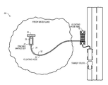
- FIG. 1 is a schematic side diagram of an aquatic vegetation harvesting system in accordance with an embodiment of the present invention
- FIG. 2 is a schematic top view diagram of the aquatic vegetation harvesting system of FIG. 1 ;
- FIG. 3 is a schematic top view diagram of the aquatic vegetation harvesting system of FIG. 1 showing a possible orientation on a body of water relative to a shore;
- FIG. 4 is a schematic top view diagram of an alternative possible vegetation harvesting system of FIG. 1 showing a possible floating barge for processing vegetation for transporting the processed vegetation to shore;
- FIG. 5 is schematic top view diagram of the floating processing barge of FIG. 4 ;
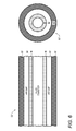
- FIG. 6 is a cross-sectional view of a possible floating tube used to transport processed vegetation to shore in accordance with an embodiment of the present invention
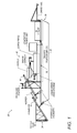
- FIG. 7 is a side schematic view of an alternative possible vegetation harvesting system having a possible articulated floating tracked vehicle with a pivoting joint positioned between two floating tracked sections;
- FIG. 8 is a front view of the alternative possible vegetation harvesting system of FIG. 7 ;
- FIG. 9 is a top view of the alternative possible vegetation harvesting system of FIG. 7 ;
- FIG. 10 is a side, top, front and bottom view showing a possible press configuration
- FIG. 11 is a side, top, front, back and bottom view showing a possible reducer configuration
- FIG. 12 is a side schematic view of an alternative possible vegetation harvesting system having harvesting equipment mounted to a floating watercraft such as a boat in accordance with an embodiment of the invention
- FIG. 13 is a front view of the alternative possible vegetation harvesting system of FIG. 7 ;
- FIG. 14 is a top view of the alternative possible vegetation harvesting system of FIG. 7 ;
- FIG. 15 depicts an embodiment of a tracked floating vehicle
- FIG. 16 depicts an alternate embodiment of a tracked floating vehicle
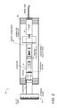
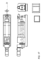
- FIG. 17 depicts a schematic diagram of a press
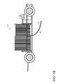
- FIG. 18 depicts an embodiment of a hose reel
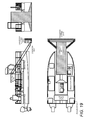
- FIG. 19 depicts an embodiment of a powered platform
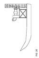
- FIG. 20 depicts an embodiment of a propulsion system.
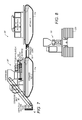
- FIGS. 1-6 An aquatic vegetation harvesting system 20 is shown and described in FIGS. 1-6 .
- the harvesting system 20 includes a water-based vehicle 22 , which is preferably a tracked, floating vehicle that operates equally well in shallow and deep water, with a vegetation cutting system 24 , grinding system 26 , liquefying system 28 and vegetation transmitting system 30 operably secured thereto.
- the preferred vehicle 22 and each of these systems are discussed in detail below.
- the system includes a floating tracked vehicle 22 such as shown in FIGS. 15-16 .
- a floating tracked vehicle 22 such as shown in FIGS. 15-16 .
- a floating vehicle known as the “Wilson Marsh Buggy” that is used to transport equipment, materials and personnel through shallow water, swamps and marshes can be adapted to serve as the vehicle for this system.
- the vehicle may be a conventional floating barge as shown in FIGS. 1-2 .
- the cutting system 24 can include a conventional cross auger 40 and a cutter head 42 extending from the vehicle to operably engage the vegetation to be cut.
- a conveyor 44 can transmit the cut vegetation up and onto the vehicle 22 for further processing.
- the cut vegetation is preferably further processed on board the vehicle 22 with a grinding system 26 operably secured to receive the cut vegetation from the conveyor 44 and transfer finely ground vegetation to the liquefying system 28 .
- the liquefying system 28 is preferably an industrial “Screw Press” which takes vegetation and turns it into a liquefied state for easy pumping/transportation to shore. Once liquefied, the product is sent to the transmitting system.
- One possible preferred screw press is one currently manufactured in Tampa, Fla. and called the “Vincent Screw Press. This type of press may work particularly well for this purpose. Additional information regarding the preferred screw press is provided in FIG. 17 .
- the grinder known as a “Muffin Monster Grinder” will also operate well in this environment.
- the grinder is preferably mounted onto the screw press.
- the purpose of the grinder is to increase throughput and more importantly protect the screw press from foreign material that may cause damage.
- the grinder is designed to handle any material that may be found in the waterways including wood, plastic and the like.
- Finely ground vegetation is transmitted to the shore with a transmitting system 30 operably secured to the vehicle.
- the system includes a pump 50 and a discharge hose 52 , which is preferably a floating tube 52 ′, extending from the vehicle 22 to the shore 60 as shown in FIGS. 4 and 5 , or alternatively to a storage barge.
- a swing tube is preferably operably secured to the vehicle 22 to move the discharge hose 52 and ensure it is out of the way when the vehicle 22 turns around or backs up.
- the swing tube is preferably located at the back of the vehicle 22 .
- a generator 62 powers pump 50 and the other components of the system 20 .
- the floating tube 52 ′ has the ability to roll onto a reel 70 while pumping as shown in FIG. 18 .
- a conventional high pressure hose will not float effectively without attachment of buoys.
- the preferred tube 52 remains buoyant by positioning an inner tube 80 within a larger cross-sectional area larger tube 82 as shown. The finely ground vegetation is transmitted through the inner tube 80 , while the gap 84 between the inner and outer tubes contains air or other gas, thereby allowing the tube 52 to float without the need for buoys. This is important as efficiency is critical in reducing the costs to the Water Management Agencies, thereby reducing the amounts of poisonous herbicides from our drinking water.
- the “self-floating” hose allows for fast deployment, redeployment and retrieval.
- An exemplary tube 52 ′ construction found to work particularly well includes placing a smaller diameter hose inside a standard 5.5 inch diameter hose resulting in an effective air gap between the two hoses. By sealing the air inside the gap, the hose will float even when the inner hose is filled with finely ground liquefied aquatic vegetation.
- the Continuous Manure Application Reel 90 allows the hose to be easily rolled in and out as necessary, can include a booster pump to pump finely ground and liquefied vegetation to shore, can sit on its own barge, and can provide its own diesel power or the like to run the booster pump, reel and drive system as needed.
- the finely ground and liquefied vegetation can be loaded into tanker trucks or the like for transport.
- the currently available aquatic vegetation harvesting system 20 is designed to go in waters that are minimally 24′′ to 36′′ deep. When current harvesters enter shallower waters, they get stuck in the muddy bottom of the lake—swamp. This creates a large problem for State agencies, as an example, Florida has the Florida Everglades that need massive harvesting and current designed equipment cannot service that body of water due to it being a shallow water swamp.
- harvesting of aquatic weeds requires the removal of said weeds to shore.
- Our design can also transport the harvested weeds to the on-shore drop off location. This harvesting system can cut, collect and haul weeds to shore.
- controlling laws may require the removal of the weeds as they contain high concentration of nutrients, such as phosphorus and nitrogen.
- nutrients such as phosphorus and nitrogen.
- the Florida Fish and Wildlife department correctly state that this is the main culprit in algae outbreaks and further aquatic weed proliferation.
- our invention includes “liquefying” the aquatic weeds on the harvester itself or on a barge close by. Once weeds are liquefied through the use of a “screw press”, they are pumped through a floating hose to shore where the liquids are then hauled away. It is predicted our new system will be sufficiently more efficient due to the time saving issues on not having to transport the weeds to shore.
- the standard harvester would harvest a load of weeds and turn around and deliver the harvested weeds to the floating barge which would be only be a few yards from the harvester so the turnaround time to off load weeds is fast.
- a water-taxi system is another extant system that can be used unload the harvester while still harvesting and transport said load to the barge for processing, losing zero production time.
- the barge would receive the harvested weeds via a conveyor, then liquefied and pumped to shore through a floating hose and trucked away by tanker trucks.
- the purpose of this design is to have a hose-in-a-hose system that can have liquid being pumped through the inside hose and float.
- the hose we will be using is the same hard hose used on hose reels for irrigation systems.
- the key difference is our new design has a smaller hose on the inside of the existing hose. The smaller hose will be used to pump the liquid and the larger outer hose to hold the air pressure for buoyancy.
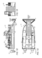
- an alternative tracked vehicle 20 ′ is disclosed.
- the alternative tracked vehicle 20 ′ of this embodiment includes a forward floating tracked vehicle 22 a and an aft floating tracked vehicle 22 b joined together at a pivot point 125 , preferably with a knuckle joint 130 . This allows the forward and aft floating tacked vehicles 22 a , 22 b (respectively) to pivot with respect to each other about the pivot point 125 .
- hydraulic cylinders 132 in communication with a control system (not shown) operably engage the forward and aft floating tracked vehicles 22 a , 22 b (respectively) to allow the pivot position to between the two floating tracked vehicles to be selected by an operator.
- the vehicle 20 ′ may be steered by the operator operating the onboard propulsion systems on one or both vehicles 22 a , 22 b and selecting a desired pivot angle between the forward and aft floating tracked vehicles 22 a , 22 b.
- Harvesting equipment may be mounted to either the forward or the aft floating tracked vehicles as desired.
- FIG. 7 one possible orientation of equipment is shown with the processing equipment mounted to the forward tracked vehicle and the power pack mounted to the aft tracked vehicle. Additional harvesting equipment may also be mounted to one or the other of the tracked vehicle as needed.
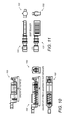
- a preferred press 100 known as a Vincent IKP16 press is shown.
- a preferred reducer 102 arrangement is shown.
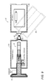
- an alternative vehicle 20 ′ for carrying the vegetation harvesting equipment is disclosed.
- the alternative vehicle 20 ′ of this embodiment includes a trackless floating watercraft such as a boat 300 or the like.
- the trackless floating watercraft can include a wide lower surface and a shallow hull for allowing the watercraft to float in shallow water even when heavily loaded with harvesting equipment.
- a propulsion system such as one or more outboard motors 302 and the like can be mounted to the watercraft.
- Harvested biomass may be stored in a collection tank 304 mounted within the hull of the watercraft.
- Harvesting equipment may be mounted to either the forward or the aft floating tracked vehicles as desired. In FIG. 12 , one possible orientation of equipment is shown with the processing equipment mounted to the forward tracked vehicle and the power pack mounted to the aft tracked vehicle. Additional harvesting equipment may also be mounted to one or the other of the tracked vehicle as needed.
Landscapes
- Life Sciences & Earth Sciences (AREA)
- Engineering & Computer Science (AREA)
- Mechanical Engineering (AREA)
- Environmental Sciences (AREA)
- Pest Control & Pesticides (AREA)
- Insects & Arthropods (AREA)
- Marine Sciences & Fisheries (AREA)
- Wood Science & Technology (AREA)
- Zoology (AREA)
- Chemical & Material Sciences (AREA)
- Combustion & Propulsion (AREA)
- Ocean & Marine Engineering (AREA)
- Catching Or Destruction (AREA)
- Harvesting Machines For Specific Crops (AREA)
Abstract
Description
- This application claims priority to U.S. Provisional Application Ser. No. 62/396,771 entitled “AQUATIC VEGETATION HARVESTING SYSTEM” filed Sep. 19, 2016; U.S. Provisional Application Ser. No. 62/447,868 entitled “ARTICULATED VEGETATION HARVESTING SYSTEM” filed Jan. 18, 2017; and U.S. Provisional Application Ser. No. 62/447,890 entitled “FLOATING WATERCRAFT VEGETATION HARVESTING SYSTEM” filed Jan. 18, 2017, which are incorporated herein by reference in its entirety.
- The present invention relates to an apparatus and system for economically and efficiently harvesting and controlling the growth of aquatic vegetation such as weeds and the like.
- Controlling and harvesting aquatic vegetation such as weeds and the like should be a large and growing industry. However, due to lack of properly designed equipment, the industry is stagnant, if not contracting.
- This represents a massive and continuing problem for both State and Federal agencies responsible for the management of the Waterways and “Wetlands” throughout the USA and the rest of the world as well. Human sewage discharges, fertilizer washing off the farmlands and residential/commercial properties has promoted the growth of aquatic vegetation to where it is:
-
- a. Depleting the oxygen from the water and killing off marine life, thereby decimating recreational areas across America, causing massive economic losses in the billions annually.
- b. Choking the navigational waterways to where boats cannot operate there, due to the weeds clogging their props, further destroying both America's recreational areas and highly cost-effective transportation waterways.
- The Wetlands across America are a “natural filtration system” used by nature to remove pollutions from water. Again, due to the increase of “man induced” fertilizer to the waterways, the plant growth in places like the Florida Everglades have become clogged and ineffective, thereby greatly reducing to eliminating its ability to filter the water prior to going back into the aquifer and becoming the drinking water for all surrounding metropolitan cities.
- To date, systems for performing these tasks have had limited success. For example, U.S. Patent Application Publication No. 2002/0112360 to Penny, the disclosure of which is hereby incorporated by reference, discloses a tracked amphibious vehicle with a weed shredder attached thereto. The vehicle is driven along a shallow, weedy area while the shredder mows the weeds, thereby leaving the shredded vegetation in the water. This nitrogen and phosphorus rich vegetation promotes the future re-growth of weeds and is referred to by Water Management agencies as “Source Point Pollution”.
- An alternative solution to mechanical harvesting is spraying the weeds with a poisonous herbicide. But this too is problematic, as most of these weeds live in the drinking water of the local population.
- There is mechanical equipment that “harvests” the aquatic weeds, similar to a Combine used on a farm, but they are not cost effective at all, therefore way too expensive for Water Management Agencies to use. Furthermore, they can only operate in deep waters, leaving both shallow water and the Wetlands unmanaged. This leaves the Agencies with the “cost effective” but deadly-to-humans solution, poisonous herbicides.
- Thus, despite the improvements of the known aquatic harvesters, there remains a need for a cost effective harvesting system that:
-
- a. operates equally well in shallow and deep water while quickly and economically harvesting the vegetation; and/or,
- b. quickly and economically transports the harvested vegetation to shore, removing from the water system the plants and their nitrogen and phosphorus values contained therein, thereby eliminating Source Point Pollution.
The present invention disclosed herein fulfills these and other needs.
- Advantages of the present invention will become apparent to those skilled in the art with the benefit of the following detailed description of embodiments and upon reference to the accompanying drawings in which:
-
FIG. 1 is a schematic side diagram of an aquatic vegetation harvesting system in accordance with an embodiment of the present invention; -
FIG. 2 is a schematic top view diagram of the aquatic vegetation harvesting system ofFIG. 1 ; -
FIG. 3 is a schematic top view diagram of the aquatic vegetation harvesting system ofFIG. 1 showing a possible orientation on a body of water relative to a shore; -
FIG. 4 is a schematic top view diagram of an alternative possible vegetation harvesting system ofFIG. 1 showing a possible floating barge for processing vegetation for transporting the processed vegetation to shore; -
FIG. 5 is schematic top view diagram of the floating processing barge ofFIG. 4 ; -
FIG. 6 is a cross-sectional view of a possible floating tube used to transport processed vegetation to shore in accordance with an embodiment of the present invention; -
FIG. 7 is a side schematic view of an alternative possible vegetation harvesting system having a possible articulated floating tracked vehicle with a pivoting joint positioned between two floating tracked sections; -
FIG. 8 is a front view of the alternative possible vegetation harvesting system ofFIG. 7 ; -
FIG. 9 is a top view of the alternative possible vegetation harvesting system ofFIG. 7 ; -
FIG. 10 is a side, top, front and bottom view showing a possible press configuration; -
FIG. 11 is a side, top, front, back and bottom view showing a possible reducer configuration; -
FIG. 12 is a side schematic view of an alternative possible vegetation harvesting system having harvesting equipment mounted to a floating watercraft such as a boat in accordance with an embodiment of the invention; -
FIG. 13 is a front view of the alternative possible vegetation harvesting system ofFIG. 7 ; and -
FIG. 14 is a top view of the alternative possible vegetation harvesting system ofFIG. 7 ; -
FIG. 15 depicts an embodiment of a tracked floating vehicle; -
FIG. 16 depicts an alternate embodiment of a tracked floating vehicle; -
FIG. 17 depicts a schematic diagram of a press; -
FIG. 18 depicts an embodiment of a hose reel; -
FIG. 19 depicts an embodiment of a powered platform; and -
FIG. 20 depicts an embodiment of a propulsion system. - While the invention may be susceptible to various modifications and alternative forms, specific embodiments thereof are shown by way of example in the drawings and will herein be described in detail. The drawings may not be to scale. It should be understood, however, that the drawings and detailed description thereto are not intended to limit the invention to the particular form disclosed, but to the contrary, the intention is to cover all modifications, equivalents, and alternatives falling within the spirit and scope of the present invention as defined by the appended claims.
- It is to be understood the present invention is not limited to particular devices or methods, which may, of course, vary. It is also to be understood that the terminology used herein is for the purpose of describing particular embodiments only, and is not intended to be limiting. As used in this specification and the appended claims, the singular forms “a”, “an”, and “the” include singular and plural referents unless the content clearly dictates otherwise. Furthermore, the word “may” is used throughout this application in a permissive sense (i.e., having the potential to, being able to), not in a mandatory sense (i.e., must). The term “include,” and derivations thereof, mean “including, but not limited to.” The term “coupled” means directly or indirectly connected.
- An aquatic
vegetation harvesting system 20 is shown and described inFIGS. 1-6 . As best shown inFIGS. 1 and 2 , theharvesting system 20 includes a water-basedvehicle 22, which is preferably a tracked, floating vehicle that operates equally well in shallow and deep water, with avegetation cutting system 24, grindingsystem 26, liquefyingsystem 28 andvegetation transmitting system 30 operably secured thereto. Thepreferred vehicle 22 and each of these systems are discussed in detail below. - Preferably, the system includes a floating tracked
vehicle 22 such as shown inFIGS. 15-16 . This allows the system to operate in shallow water by the vehicle operating on its tracks and in deep water with the vehicle floating. A floating vehicle known as the “Wilson Marsh Buggy” that is used to transport equipment, materials and personnel through shallow water, swamps and marshes can be adapted to serve as the vehicle for this system. Alternatively, in some situations, the vehicle may be a conventional floating barge as shown inFIGS. 1-2 . - As shown in
FIGS. 1 and 2 , the cuttingsystem 24 can include aconventional cross auger 40 and acutter head 42 extending from the vehicle to operably engage the vegetation to be cut. Aconveyor 44 can transmit the cut vegetation up and onto thevehicle 22 for further processing. - The cut vegetation is preferably further processed on board the
vehicle 22 with a grindingsystem 26 operably secured to receive the cut vegetation from theconveyor 44 and transfer finely ground vegetation to the liquefyingsystem 28. - The liquefying
system 28 is preferably an industrial “Screw Press” which takes vegetation and turns it into a liquefied state for easy pumping/transportation to shore. Once liquefied, the product is sent to the transmitting system. One possible preferred screw press is one currently manufactured in Tampa, Fla. and called the “Vincent Screw Press. This type of press may work particularly well for this purpose. Additional information regarding the preferred screw press is provided inFIG. 17 . - The grinder known as a “Muffin Monster Grinder” will also operate well in this environment. The grinder is preferably mounted onto the screw press. The purpose of the grinder is to increase throughput and more importantly protect the screw press from foreign material that may cause damage. The grinder is designed to handle any material that may be found in the waterways including wood, plastic and the like.
- Finely ground vegetation is transmitted to the shore with a transmitting
system 30 operably secured to the vehicle. Preferably, the system includes apump 50 and adischarge hose 52, which is preferably a floatingtube 52′, extending from thevehicle 22 to the shore 60 as shown inFIGS. 4 and 5 , or alternatively to a storage barge. A swing tube is preferably operably secured to thevehicle 22 to move thedischarge hose 52 and ensure it is out of the way when thevehicle 22 turns around or backs up. The swing tube is preferably located at the back of thevehicle 22. A generator 62, powers pump 50 and the other components of thesystem 20. - More preferably, the floating
tube 52′ has the ability to roll onto areel 70 while pumping as shown inFIG. 18 . A conventional high pressure hose will not float effectively without attachment of buoys. Referring toFIG. 6 , thepreferred tube 52 remains buoyant by positioning aninner tube 80 within a larger cross-sectional arealarger tube 82 as shown. The finely ground vegetation is transmitted through theinner tube 80, while thegap 84 between the inner and outer tubes contains air or other gas, thereby allowing thetube 52 to float without the need for buoys. This is important as efficiency is critical in reducing the costs to the Water Management Agencies, thereby reducing the amounts of poisonous herbicides from our drinking water. The “self-floating” hose allows for fast deployment, redeployment and retrieval. Plus, with the ability to add or decrease air pressure within the air-chamber of the hose, we can raise or lower the depth of the hose to where it lays on the waterway bed, or any distance from the bed to floating on the surface. This is critical as we can adjust the hose if and whenever it becomes a navigational hazard without stopping the harvest production. - An
exemplary tube 52′ construction found to work particularly well includes placing a smaller diameter hose inside a standard 5.5 inch diameter hose resulting in an effective air gap between the two hoses. By sealing the air inside the gap, the hose will float even when the inner hose is filled with finely ground liquefied aquatic vegetation. - Referring to
FIG. 18 , the Continuous Manure Application Reel 90 (CMA REEL) allows the hose to be easily rolled in and out as necessary, can include a booster pump to pump finely ground and liquefied vegetation to shore, can sit on its own barge, and can provide its own diesel power or the like to run the booster pump, reel and drive system as needed. - Once pumped to shore, the finely ground and liquefied vegetation can be loaded into tanker trucks or the like for transport.
- The currently available aquatic
vegetation harvesting system 20 is designed to go in waters that are minimally 24″ to 36″ deep. When current harvesters enter shallower waters, they get stuck in the muddy bottom of the lake—swamp. This creates a large problem for State agencies, as an example, Florida has the Florida Everglades that need massive harvesting and current designed equipment cannot service that body of water due to it being a shallow water swamp. - By installing
tracks 100 on a standard aquatic weed harvester we now can do both shallow waters as well as deep waters with the same machine, as shown inFIGS. 15-16 . - Secondly, by definition, “harvesting” of aquatic weeds requires the removal of said weeds to shore. Our design can also transport the harvested weeds to the on-shore drop off location. This harvesting system can cut, collect and haul weeds to shore.
- Moreover, controlling laws may require the removal of the weeds as they contain high concentration of nutrients, such as phosphorus and nitrogen. For example, the Florida Fish and Wildlife department correctly state that this is the main culprit in algae outbreaks and further aquatic weed proliferation.
- The challenge with the current models of aquatic weed harvester is time and hence, expense required to haul the harvested weeds to shore. This makes mechanical harvesting expensive and less viable as the aquatic weeds need to be hauled long distances across a body of water.
- To make the process more time effective, and hence, significantly more affordable, our invention includes “liquefying” the aquatic weeds on the harvester itself or on a barge close by. Once weeds are liquefied through the use of a “screw press”, they are pumped through a floating hose to shore where the liquids are then hauled away. It is predicted our new system will be sufficiently more efficient due to the time saving issues on not having to transport the weeds to shore.
- In the event we are only harvesting in deep water, a standard aquatic weed harvester can be used. In this case, our “system of liquefaction” of the weeds would be close by on a floating barge.
- The standard harvester would harvest a load of weeds and turn around and deliver the harvested weeds to the floating barge which would be only be a few yards from the harvester so the turnaround time to off load weeds is fast. A water-taxi system is another extant system that can be used unload the harvester while still harvesting and transport said load to the barge for processing, losing zero production time. The barge would receive the harvested weeds via a conveyor, then liquefied and pumped to shore through a floating hose and trucked away by tanker trucks.
- In the event the floating hose is not an option (waterway navigational hazard, distance), we will use liquid tanks on floating barges (and/or the tanks themselves can be floatable) to receive the liquefied plants. Once the tanks are full, they would be hauled and/or floated to shore.
- The purpose of this design is to have a hose-in-a-hose system that can have liquid being pumped through the inside hose and float. The hose we will be using is the same hard hose used on hose reels for irrigation systems. The key difference is our new design has a smaller hose on the inside of the existing hose. The smaller hose will be used to pump the liquid and the larger outer hose to hold the air pressure for buoyancy.
- It is particularly useful that we are able to continuously pump liquid from the harvester to shore. This way we never have to stop harvesting in a given area. This hose system would have a reach of approximately 2,500 feet (half a mile) from the hose reel. Therefore, our system can harvest a large area before we would have to stop harvesting and reset up. The State of Florida currently spends 20 million dollars on chemicals poisons to battle the proliferation of the noxious aquatic weed Hydrilla alone. The Fish and Wildlife officials have said that currently using chemicals to battle Hydrilla and other aquatic weeds is their only viable option at this time. Our invention will challenge that, thereby removing many thousands of metric tons of poisons from our daily drinking water.
- Referring to
FIGS. 7-1 ′l, an alternative trackedvehicle 20′ is disclosed. In order to minimize undue repetition, like elements between the disclosed embodiments are like numbered. The alternative trackedvehicle 20′ of this embodiment includes a forward floating trackedvehicle 22 a and an aft floating trackedvehicle 22 b joined together at apivot point 125, preferably with aknuckle joint 130. This allows the forward and aft floating tackedvehicles pivot point 125. - Preferably,
hydraulic cylinders 132 in communication with a control system (not shown) operably engage the forward and aft floating trackedvehicles vehicle 20′ may be steered by the operator operating the onboard propulsion systems on one or bothvehicles vehicles - Harvesting equipment may be mounted to either the forward or the aft floating tracked vehicles as desired. In
FIG. 7 , one possible orientation of equipment is shown with the processing equipment mounted to the forward tracked vehicle and the power pack mounted to the aft tracked vehicle. Additional harvesting equipment may also be mounted to one or the other of the tracked vehicle as needed. - Referring to
FIG. 10 , apreferred press 100 known as a Vincent IKP16 press is shown. Referring toFIG. 11 , apreferred reducer 102 arrangement is shown. - Referring to
FIGS. 12-14 , analternative vehicle 20′ for carrying the vegetation harvesting equipment is disclosed. In order to minimize undue repetition, like elements between the disclosed embodiments are like numbered. Thealternative vehicle 20′ of this embodiment includes a trackless floating watercraft such as aboat 300 or the like. - The trackless floating watercraft can include a wide lower surface and a shallow hull for allowing the watercraft to float in shallow water even when heavily loaded with harvesting equipment. A propulsion system such as one or more
outboard motors 302 and the like can be mounted to the watercraft. Harvested biomass may be stored in acollection tank 304 mounted within the hull of the watercraft. - Harvesting equipment may be mounted to either the forward or the aft floating tracked vehicles as desired. In
FIG. 12 , one possible orientation of equipment is shown with the processing equipment mounted to the forward tracked vehicle and the power pack mounted to the aft tracked vehicle. Additional harvesting equipment may also be mounted to one or the other of the tracked vehicle as needed. - In this patent, certain U.S. patents, U.S. patent applications, and other materials (e.g., articles) have been incorporated by reference. The text of such U.S. patents, U.S. patent applications, and other materials is, however, only incorporated by reference to the extent that no conflict exists between such text and the other statements and drawings set forth herein. In the event of such conflict, then any such conflicting text in such incorporated by reference U.S. patents, U.S. patent applications, and other materials is specifically not incorporated by reference in this patent.
- Further modifications and alternative embodiments of various aspects of the invention will be apparent to those skilled in the art in view of this description. Accordingly, this description is to be construed as illustrative only and is for the purpose of teaching those skilled in the art the general manner of carrying out the invention. It is to be understood that the forms of the invention shown and described herein are to be taken as examples of embodiments. Elements and materials may be substituted for those illustrated and described herein, parts and processes may be reversed, and certain features of the invention may be utilized independently, all as would be apparent to one skilled in the art after having the benefit of this description of the invention. Changes may be made in the elements described herein without departing from the spirit and scope of the invention as described in the following claims.
Claims (16)
Priority Applications (1)
| Application Number | Priority Date | Filing Date | Title |
|---|---|---|---|
| US15/709,406 US10602663B2 (en) | 2016-09-19 | 2017-09-19 | Aquatic vegetation harvesting system |
Applications Claiming Priority (4)
| Application Number | Priority Date | Filing Date | Title |
|---|---|---|---|
| US201662396771P | 2016-09-19 | 2016-09-19 | |
| US201762447890P | 2017-01-18 | 2017-01-18 | |
| US201762447868P | 2017-01-18 | 2017-01-18 | |
| US15/709,406 US10602663B2 (en) | 2016-09-19 | 2017-09-19 | Aquatic vegetation harvesting system |
Publications (2)
| Publication Number | Publication Date |
|---|---|
| US20180098497A1 true US20180098497A1 (en) | 2018-04-12 |
| US10602663B2 US10602663B2 (en) | 2020-03-31 |
Family
ID=61829460
Family Applications (1)
| Application Number | Title | Priority Date | Filing Date |
|---|---|---|---|
| US15/709,406 Active 2038-01-20 US10602663B2 (en) | 2016-09-19 | 2017-09-19 | Aquatic vegetation harvesting system |
Country Status (1)
| Country | Link |
|---|---|
| US (1) | US10602663B2 (en) |
Cited By (3)
| Publication number | Priority date | Publication date | Assignee | Title |
|---|---|---|---|---|
| CN114980728A (en) * | 2019-12-02 | 2022-08-30 | 飞拓公司 | System and method for aquatic plant harvesting |
| CN116249647A (en) * | 2020-11-06 | 2023-06-09 | 唐山圣因海洋科技有限公司 | Suspension cleaning equipment for aquaculture |
| US20240239537A1 (en) * | 2021-05-21 | 2024-07-18 | Climate Foundation | Apparatuses devices and methods for harvesting or collecting seaweed and aquatic flora from large bodies of water for storing and transporting seaweed and aquatic flora |
Family Cites Families (28)
| Publication number | Priority date | Publication date | Assignee | Title |
|---|---|---|---|---|
| US3546858A (en) * | 1969-02-10 | 1970-12-15 | Merle P Chaplin | Harvesting marine growths |
| US3626675A (en) * | 1969-11-10 | 1971-12-14 | Merle P Chaplin | Weed pump |
| US3750723A (en) * | 1971-01-04 | 1973-08-07 | Air Logistics Corp | Single point mooring system |
| US3866396A (en) * | 1971-05-10 | 1975-02-18 | Dorman A Meyer | Removal of marine growths from lakes, waterways, and other bodies of water |
| US4258534A (en) * | 1979-03-07 | 1981-03-31 | Bryant Charles B | Aquatic harvesting apparatus |
| US4764137A (en) * | 1986-11-13 | 1988-08-16 | Frank Schulte | Floatable dredge hose |
| US6023920A (en) | 1997-12-18 | 2000-02-15 | The Master's Dredging Company, Inc. | Apparatus for destroying aquatic vegetation |
| US6116004A (en) | 1998-10-07 | 2000-09-12 | The Master's Dredging Company | Aquatic vegetation shredder |
| US6725637B2 (en) | 1998-10-09 | 2004-04-27 | Trent G. Snider | Water craft for reducing aquatic plant infestation |
| US6250054B1 (en) | 1998-12-07 | 2001-06-26 | William E. Kramer | Device for removal of aquatic vegetation |
| US6449931B1 (en) | 2000-02-02 | 2002-09-17 | The Master's Dredging Company, Inc. | Aquatic vegetation shredder having bow and stern mounted high speed, large chopping propellers |
| US6357213B1 (en) * | 2000-06-14 | 2002-03-19 | Mark L. Dillingham | Water vegetation removal system |
| US6393812B1 (en) | 2000-10-31 | 2002-05-28 | Hydromentia, Inc. | Method and apparatus for gathering, transporting, and processing aquatic plants |
| US20020095921A1 (en) | 2001-01-25 | 2002-07-25 | The Master's Dredging Company, Inc. | Airboat with aquatic vegetation shredding assembly |
| US20020112460A1 (en) * | 2001-02-21 | 2002-08-22 | The Master's Dredging Company, Inc. | Tracked amphibious vehicle with aquatic vegetation shredding assembly |
| US6910319B2 (en) | 2001-12-05 | 2005-06-28 | David Castleberry | Hydrojet for cutting plant growth from waterways |
| WO2004017715A1 (en) | 2002-08-26 | 2004-03-04 | Freshwater Environmental Management Pty Ltd | Aquatic plant harvester |
| US6672039B1 (en) | 2002-09-16 | 2004-01-06 | Clarence W. Shonnard | Apparatus and method for cutting and harvesting infestations of aquatic vegetation in shallow areas of water bodies |
| US6832465B2 (en) | 2002-10-24 | 2004-12-21 | Ronald F. Horvath | Aquatic weeding device |
| US7036295B1 (en) | 2005-03-28 | 2006-05-02 | Vaughan James A | Aquatic growth harvester |
| US7958705B1 (en) * | 2008-05-20 | 2011-06-14 | Bourque John R | Waterborne vegetation harvesting apparatus |
| US8381500B2 (en) | 2008-10-15 | 2013-02-26 | John Grimes | Aquatic weed harvester |
| US8359819B1 (en) | 2009-01-13 | 2013-01-29 | Dennis W Timm | Lake weed harvester |
| US8734195B2 (en) * | 2011-10-28 | 2014-05-27 | Great Lakes Dredge & Dock Company, Llc | Mooring buoy assembly |
| US8826634B2 (en) | 2011-12-20 | 2014-09-09 | Stephen Landry, Jr. | Method and apparatus for cutting aquatic vegetation |
| US9060464B2 (en) | 2012-09-07 | 2015-06-23 | Liquid Waste Technology, Llc | Method and apparatus for dredging and removing aquatic vegetation |
| US9493215B2 (en) | 2013-06-12 | 2016-11-15 | Liquid Waste Technology, Llc | Floating debris harvesting system |
| US10051788B2 (en) * | 2016-07-06 | 2018-08-21 | Mark Jirik | Duckweed removal and collection device |
-
2017
- 2017-09-19 US US15/709,406 patent/US10602663B2/en active Active
Cited By (3)
| Publication number | Priority date | Publication date | Assignee | Title |
|---|---|---|---|---|
| CN114980728A (en) * | 2019-12-02 | 2022-08-30 | 飞拓公司 | System and method for aquatic plant harvesting |
| CN116249647A (en) * | 2020-11-06 | 2023-06-09 | 唐山圣因海洋科技有限公司 | Suspension cleaning equipment for aquaculture |
| US20240239537A1 (en) * | 2021-05-21 | 2024-07-18 | Climate Foundation | Apparatuses devices and methods for harvesting or collecting seaweed and aquatic flora from large bodies of water for storing and transporting seaweed and aquatic flora |
Also Published As
| Publication number | Publication date |
|---|---|
| US10602663B2 (en) | 2020-03-31 |
Similar Documents
| Publication | Publication Date | Title |
|---|---|---|
| US11097815B2 (en) | Vessel for cleaning waste in shallow waters | |
| US8479481B2 (en) | Aquatic plant harvester | |
| US10602663B2 (en) | Aquatic vegetation harvesting system | |
| CA2945864C (en) | Device for collecting and removing plastic, sludge-like materials deposited on the beds of bodies of water | |
| CA2840478C (en) | Method and apparatus for harvesting pollution from a body of water | |
| CN110709318B (en) | Floating and manoeuvrable hull washing and cleaning device for a marine vessel | |
| US3546858A (en) | Harvesting marine growths | |
| US8673155B2 (en) | Oil spill recovery method, vessel and apparatus | |
| CN102285428B (en) | Shoal hybrid driven aquatic plant harvesting ship | |
| GB2486286A (en) | Oil spill recovery vessel | |
| CA2846047C (en) | Apparatus for transporting pollution from a body of water | |
| CA2758915A1 (en) | Method and apparatus for harvesting beached seaweed by vacuum | |
| US7958705B1 (en) | Waterborne vegetation harvesting apparatus | |
| US3698163A (en) | Aquatic harvester | |
| Kader et al. | Design of rubbish collecting system for inland waterways | |
| US8899165B2 (en) | Folding floating vessel | |
| US11878780B1 (en) | Autonomous hull biofouling cleaning system | |
| CN202180917U (en) | Shoal combined-driven water plant harvesting boat | |
| AU2018285355B2 (en) | System and method for use in fish farming or marine harvesting | |
| US3847105A (en) | Aquatic harvester | |
| US4507909A (en) | Compactor and paddle wheel for aquatic harvester | |
| WO2012027620A2 (en) | Treatment system and method for shallow water and saturated soil environments | |
| EP4179868B1 (en) | Combination of a workboat and a transport module and method of operating such a combination | |
| CN201023402Y (en) | Urban environmental protection amphibious multifunctional ship | |
| GB2473165A (en) | Oil spill recovery vessel having an oil transfer bollard and oil spill recovery method |
Legal Events
| Date | Code | Title | Description |
|---|---|---|---|
| FEPP | Fee payment procedure |
Free format text: ENTITY STATUS SET TO UNDISCOUNTED (ORIGINAL EVENT CODE: BIG.); ENTITY STATUS OF PATENT OWNER: MICROENTITY |
|
| FEPP | Fee payment procedure |
Free format text: ENTITY STATUS SET TO MICRO (ORIGINAL EVENT CODE: MICR); ENTITY STATUS OF PATENT OWNER: MICROENTITY Free format text: ENTITY STATUS SET TO SMALL (ORIGINAL EVENT CODE: SMAL); ENTITY STATUS OF PATENT OWNER: MICROENTITY |
|
| STPP | Information on status: patent application and granting procedure in general |
Free format text: NON FINAL ACTION MAILED |
|
| STPP | Information on status: patent application and granting procedure in general |
Free format text: RESPONSE TO NON-FINAL OFFICE ACTION ENTERED AND FORWARDED TO EXAMINER |
|
| STPP | Information on status: patent application and granting procedure in general |
Free format text: NOTICE OF ALLOWANCE MAILED -- APPLICATION RECEIVED IN OFFICE OF PUBLICATIONS |
|
| STPP | Information on status: patent application and granting procedure in general |
Free format text: PUBLICATIONS -- ISSUE FEE PAYMENT VERIFIED |
|
| STCF | Information on status: patent grant |
Free format text: PATENTED CASE |
|
| AS | Assignment |
Owner name: AGUACULTURE LIMITED LIABILITY COMPANY, FLORIDA Free format text: ASSIGNMENT OF ASSIGNORS INTEREST;ASSIGNOR:SZABO, NICHOLAS;REEL/FRAME:056534/0242 Effective date: 20201127 |
|
| MAFP | Maintenance fee payment |
Free format text: PAYMENT OF MAINTENANCE FEE, 4TH YEAR, MICRO ENTITY (ORIGINAL EVENT CODE: M3551); ENTITY STATUS OF PATENT OWNER: MICROENTITY Year of fee payment: 4 |