US20180098492A1 - Grass trimmer, operating method thereof and control method thereof - Google Patents
Grass trimmer, operating method thereof and control method thereof Download PDFInfo
- Publication number
- US20180098492A1 US20180098492A1 US15/839,257 US201715839257A US2018098492A1 US 20180098492 A1 US20180098492 A1 US 20180098492A1 US 201715839257 A US201715839257 A US 201715839257A US 2018098492 A1 US2018098492 A1 US 2018098492A1
- Authority
- US
- United States
- Prior art keywords
- spool
- trimming
- grass trimmer
- line
- auto
- Prior art date
- Legal status (The legal status is an assumption and is not a legal conclusion. Google has not performed a legal analysis and makes no representation as to the accuracy of the status listed.)
- Granted
Links
Images


Classifications
-
- A—HUMAN NECESSITIES
- A01—AGRICULTURE; FORESTRY; ANIMAL HUSBANDRY; HUNTING; TRAPPING; FISHING
- A01D—HARVESTING; MOWING
- A01D34/00—Mowers; Mowing apparatus of harvesters
- A01D34/01—Mowers; Mowing apparatus of harvesters characterised by features relating to the type of cutting apparatus
- A01D34/412—Mowers; Mowing apparatus of harvesters characterised by features relating to the type of cutting apparatus having rotating cutters
- A01D34/416—Flexible line cutters
- A01D34/4166—Mounting or replacement of the lines
-
- A—HUMAN NECESSITIES
- A01—AGRICULTURE; FORESTRY; ANIMAL HUSBANDRY; HUNTING; TRAPPING; FISHING
- A01D—HARVESTING; MOWING
- A01D34/00—Mowers; Mowing apparatus of harvesters
- A01D34/01—Mowers; Mowing apparatus of harvesters characterised by features relating to the type of cutting apparatus
- A01D34/412—Mowers; Mowing apparatus of harvesters characterised by features relating to the type of cutting apparatus having rotating cutters
- A01D34/416—Flexible line cutters
- A01D34/4161—Means for feeding cutter line
- A01D34/4163—Means for feeding cutter line by triggered line feedout, e.g. bump-feeding
-
- A—HUMAN NECESSITIES
- A01—AGRICULTURE; FORESTRY; ANIMAL HUSBANDRY; HUNTING; TRAPPING; FISHING
- A01D—HARVESTING; MOWING
- A01D34/00—Mowers; Mowing apparatus of harvesters
- A01D34/01—Mowers; Mowing apparatus of harvesters characterised by features relating to the type of cutting apparatus
- A01D34/412—Mowers; Mowing apparatus of harvesters characterised by features relating to the type of cutting apparatus having rotating cutters
- A01D34/416—Flexible line cutters
-
- A—HUMAN NECESSITIES
- A01—AGRICULTURE; FORESTRY; ANIMAL HUSBANDRY; HUNTING; TRAPPING; FISHING
- A01D—HARVESTING; MOWING
- A01D2101/00—Lawn-mowers
-
- A—HUMAN NECESSITIES
- A01—AGRICULTURE; FORESTRY; ANIMAL HUSBANDRY; HUNTING; TRAPPING; FISHING
- A01D—HARVESTING; MOWING
- A01D34/00—Mowers; Mowing apparatus of harvesters
- A01D34/01—Mowers; Mowing apparatus of harvesters characterised by features relating to the type of cutting apparatus
- A01D34/412—Mowers; Mowing apparatus of harvesters characterised by features relating to the type of cutting apparatus having rotating cutters
- A01D34/416—Flexible line cutters
- A01D34/4165—Mounting of the cutter head
Definitions
- the present disclosure relates generally to grass trimmers and, more particularly, to a grass trimmer having an auto-winding mode, an operating method thereof and a control method thereof.
- Grass trimmers are a kind of gardening tools, which are used to trim the lawn.
- the grass trimmer includes a trimming head.
- the trimming head rotates at high speed to drive a trimming line mounted thereon to rotate so as to realize the cutting function.
- the trimming head includes a spool allowing the trimming line to wind thereon.
- the trimming line is worn away gradually due to wear. After operating for a period, it is needed to change a new trimming line and wind the new trimming line around the spool.
- a user needs to rotate the spool manually to wind the trimming line around the spool. The winding operation is inconvenient and the winding speed is slow.
- a grass trimmer in one aspect of the disclosure, includes a trimming head, a driving device for driving the trimming head to rotate so as to cut vegetation and an operating device for a user to operate so as to control the driving device.
- the trimming head includes a spool and a line holding element, the spool is used to wind a trimming line, and the line holding element is formed with a line holding structure allowing the trimming line to pass or bypass.
- the driving device includes a motor, the grass trimmer has an auto-winding mode, in the auto-winding mode, the motor drives at least one of the spool and the line holding element to make the spool and the line holding element rotate relatively so that the trimming line is wound on the spool automatically.
- an operating method for winding a trimming line of a grass trimmer includes:
- the grass trimmer including a spool allowing the trimming line to be wound thereon, a line holding element being formed with a line holding structure, and a motor being capable of driving at least one of the spool and the line holding element;
- an operating method for winding a trimming line of a grass trimmer includes:
- a control method for winding a trimming line of a grass trimmer includes a spool allowing the trimming line to be wound thereon, a line holding element being formed with a line holding structure for holding the trimming line and a motor being capable of driving at least one of the spool and the line holding element to make the spool and the line holding element rotate relatively.
- the control method includes supplying power to the motor to make the spool and the line holding element rotate relatively.
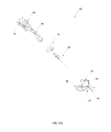
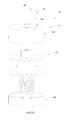
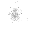
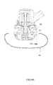
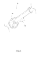
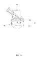
- FIG. 1A is a schematic view of an exemplary grass trimmer.
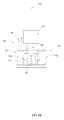
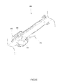
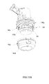
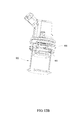
- FIG. 1B a schematic view showing the structure of a part of the grass trimmer in FIG. 1A .
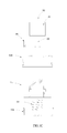
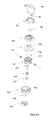
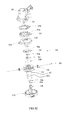
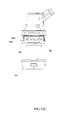
- FIG. 1C is an exploded view of the structure in FIG. 1B .
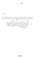
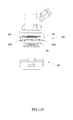
- FIG. 1D is a schematic view showing the transmission of a spool and a head housing in FIG. 1B .
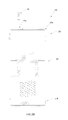
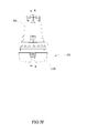
- FIG. 2A is an exploded view of an exemplary trimming head and an exemplary damping device.
- FIG. 2B is a section view of the trimming head and the damping device in FIG. 2A .
- FIG. 3A is also a schematic view of an exemplary trimming head and an exemplary damping device.
- FIG. 3B is a schematic view showing the transmission of a spool and a head housing in FIG. 3A .
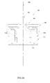
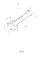
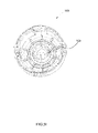
- FIG. 4A is also a schematic view of an exemplary grass trimmer.
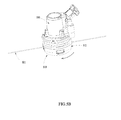
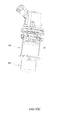
- FIG. 4B is a schematic view showing the structure of a part of the grass trimmer in FIG. 4A .
- FIG. 4C is a section view of the structure in FIG. 4B .
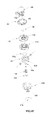
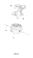
- FIG. 4D is an exploded view of the structure in FIG. 4B .
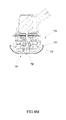
- FIG. 4E is another exploded view of the structure in FIG. 4B .
- FIG. 4F is a section view of an upper cover in FIG. 4E .
- FIG. 4G is a section view of a spool in FIG. 4E .
- FIG. 4H is a schematic view showing the inserting method of a trimming head in FIG. 4A .
- FIG. 4I is a schematic view of an operating device in FIG. 4A .
- FIG. 4J is another schematic view of the operating device in FIG. 4A , wherein a first operating element and a second operating element are in a first preset operating state and a second preset operating state respectively.
- FIG. 4K is a schematic view of an operating device.
- FIG. 4L is a schematic view showing a second operating element of the operating device in FIG. 4K , wherein the second operating element is in a second position.
- FIG. 4M is a schematic view of a line breaking device.
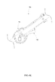
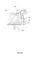
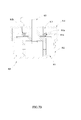
- FIG. 5A is also a schematic view of an exemplary grass trimmer.
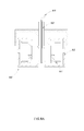
- FIG. 5B is a schematic view of a trimming head and a first housing of the grass trimmer in FIG. 5A .
- FIG. 5C is a schematic view of the trimming head and the first housing in FIG. 5B , wherein the trimming head and the first housing are separated.
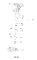
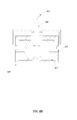
- FIG. 5D is an exploded view of the structure in FIG. 5B .
- FIG. 5E is another exploded view of the structure in FIG. 5B .
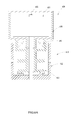
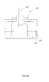
- FIG. 5F is a plane view of the structure in FIG. 5B .
- FIG. 5G is a sectional view of the structure cut along line A-A in FIG. 5F .
- FIG. 5H is a schematic view of a spool and a positioning element in FIG. 5D .
- FIG. 5I is a schematic view of a lower cover in FIG. 5D .
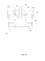
- FIG. 5J is a schematic view of the trimming head in FIG. 5F , wherein the trimming head is moved upwardly relative to the first housing.
- FIG. 5K is a sectional view of the structure cut along line B-B in FIG. 5J .
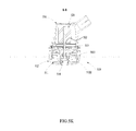
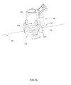
- FIG. 5L is a schematic view of a damping device in FIG. 5A .
- FIG. 5M is a schematic view of the first housing and a driving shaft in FIG. 5C .
- FIG. 5N is a sectional view of the structure cut along line C-C in FIG. 5M .
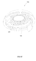
- FIG. 5O is an exploded view of the damping device in FIG. 5A .
- FIG. 5P is a plane view of the damping device in FIG. 5A , wherein a stopping element of the damping device is at a stopping position.
- FIG. 5Q is a sectional view of the structure cut along line D-D in FIG. 5P .
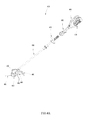
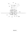
- FIG. 6A is a schematic view of a trimming head, a motor and a damping device.
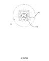
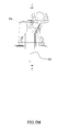
- FIG. 7A is a schematic view of an electric magnet and a trimming head.
- FIG. 7B is a schematic view of a head housing in FIG. 7A , wherein the head housing is moved relative to a spool.
- FIG. 8A is a schematic view of a head housing, wherein the head housing can be pulled by a rope.
- FIG. 8B is a schematic view of the head housing in FIG. 8 a , wherein the head housing is moved relative to a spool.
- FIG. 8C is another schematic view of a head housing, wherein the head housing can be pulled by a rope.
- FIG. 8D is a schematic view of the head housing in FIG. 8C , wherein the head housing is moved relative to a spool.
- FIG. 9A is a circuit block diagram of a grass trimmer using a brushless motor.
- FIG. 9B is a schematic view of a driving circuit in FIG. 9A .
- FIG. 9C is a circuit block diagram of a grass trimmer using a brush motor.
- FIG. 10A is a schematic view of the second operating element disposed on a connecting rod assembly.
- FIG. 10B is a schematic view of the second operating element disposed on the first housing.
- FIG. 10C is a schematic view of the second operating element disposed on a guard.
- FIG. 11A is a schematic view of a grass trimmer having a line holding element.
- FIG. 11B is a schematic view of a head housing and a spool of the grass trimmer in FIG. 11A , wherein the head housing and the spool are separated.
- FIG. 11C is a plane view of the structure in FIG. 11A .
- FIG. 11D is a schematic view of an exemplary line holding element.
- FIG. 12A is a schematic view of a trimming head and a line holding element acted as an attachment.
- FIG. 12B is a schematic view of the line holding element in FIG. 12A , wherein the line holding element is in a working state.
- FIG. 12C is a schematic view of a line frame element, wherein the line frame element is driven by a motor.
- FIG. 13A is a schematic view of an energy storing device, a motor and a trimming head.
- FIG. 13B is an enlarged view of a part of the structure in FIG. 13A .
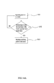
- FIG. 14A is a flow diagram showing a control method for controlling winding of a grass trimmer.
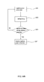
- FIG. 14B is another flow diagram showing a control method for winding of a grass trimmer.
- FIG. 14C is a flow diagram showing an operating method for winding of a grass trimmer
- a grass trimmer 100 includes a trimming head 110 , a driving device 120 and an operating device 130 .
- the trimming head 110 is configured to mount and accommodate a trimming line 101 .
- the trimming line 101 is partially accommodated in the trimming head 110 .
- the trimming line 101 has a part extending out of the trimming head 110 which is used to cut vegetation when the trimming head 110 is rotated.
- the driving device 120 is able to drive the trimming head 110 to rotate about an axis 110 a so as to cut vegetation.
- the operating device 130 is used for a user to control the grass trimmer 100 .
- the driving device 120 includes a motor 121 and a driving shaft 122 .
- the driving shaft 122 is connected with the trimming head 110 so as to drive the trimming head 110 to rotate.
- the grass trimmer 100 further includes a first housing 150 , a second housing 160 and a battery pack 170 .
- the first housing 150 is configured to mount and accommodate the motor 121 .
- the battery pack 170 acting as a power source at least can supply power to the grass trimmer 100 .
- the second housing 160 is configured to engage with the battery pack 170 detachably.
- a circuit board is accommodated in the second housing 160 , which is connected with the motor 121 electrically so that the battery pack 170 can supply power to the motor 121 and control the motor 121 .
- the first housing 150 and the second housing 160 are connected with each other through a connecting rod assembly 190 .
- the operating device 130 is fixedly mounted on the connecting rod assembly 190 .
- the grass trimmer 100 further includes an auxiliary handle 191 for the user to grip which is fixedly mounted on the connecting rod assembly 190 .
- the trimmer head 110 includes a spool 111 and a head housing 112 .
- the spool 111 is accommodated in the head housing 112 for winding the trimming line 101 .
- the spool 111 is formed with an inner aperture 111 a .
- the head housing 112 is formed with an outer aperture 112 a .
- the head housing 112 includes an upper cover 112 b and a lower cover 112 c , so that the head housing 112 is easy to assemble with the spool 111 and it is easy for the user to open the head housing 112 to check the inside of the head housing 112 .
- the trimmer head 110 includes a spring 113 which can apply a force between the head housing 112 and the spool 111 .
- the force applied by the spring 113 makes the spool 111 depart from the lower cover 112 c.
- the inner aperture 111 a and the outer aperture 112 a are aligned, and then the trimming line 101 is passed through the outer aperture 112 a and entered into the inner aperture 111 a .
- the trimming line 101 can be wound on the spool 111 under the limiting action of the outer aperture 112 a .
- the driving shaft 122 is connected with the head housing 112 , which can drive the spool 111 to rotate about the axis 110 a directly.
- the spool 111 is connected rotatably with the head housing 112 , which can rotate relative to the head housing 112 . Meanwhile, the head housing 112 is able to move relative to the spool 111 in a direction parallel to the axis 110 a.
- the spool 111 is provided with a first circumferential structure 111 b
- the head housing 112 is provided with a second circumferential structure 112 d .
- the spool 111 can move upward so that the first circumferential structure 111 b is engaged with the second circumferential structure 112 d .
- the spool 111 can be rotated synchronously with the head housing 112 .
- the first circumferential structure 111 b and the second circumferential structure 112 d have a transmitting surface therebetween which is obliquely inclined with the axis 110 a.
- the user can start the motor 121 to make the grass trimmer 100 be in a cutting mode.
- the trimming line 101 wound on the spool 111 is sufficiently long, a part of the trimming line 101 exposed out of the head housing 112 can cut the vegetation in a whipping action.
- the grass trimmer 100 further includes a damping device 140 .
- the damping device 140 includes a friction element 141 .
- the friction element 141 is connected slidably with the first housing 150 and can move along a direction A.
- the head housing 112 tends to rotate relative to the spool 111 .
- a component force in the direction of the axis 110 a is acted on the head housing 112 due to the inclined transmitting surface between the first circumferential structure 111 b and the second circumferential structure 112 d .
- the component force can overcome the spring force of the spring 113 sufficiently to make the head housing 112 move upward, so that the first circumferential structure 111 b is disengaged with the second circumferential structure 112 d .
- the spool 111 can rotate relative to the head housing 112 , and the grass trimmer 100 is in an auto-winding mode.
- the spool 111 driven by the motor 121 can rotate relative to the head housing 112 under the action of the friction element 141 so as to realize an auto-winding function.
- the spool 111 when the spool 111 is wound with enough trimming line 101 and the part of the trimming line 101 exposed out of the head housing is not long enough to cut the vegetation, the spool 111 can rotate relative to the head housing 112 so as to feed the trimming line 101 automatically for cutting purposes.
- the function of the friction element 141 is to produce damping on the head housing 112 so as to slow down the head housing 112 .
- the relative rotation is occurred between the head housing 112 and the spool 111 .
- the user can operate the friction element 141 directly or indirectly to switch the grass trimmer 100 between the cutting mode and the auto-winding mode.
- the user can operate the friction element 141 in a status corresponding to the desired mode firstly, and then start the motor 121 .
- a trimming head 210 which is similar to the trimming head 110 includes a spool 211 and a head housing 212 .
- the spool 211 and the head housing 212 are similar to the spool 111 and the head housing 112 in FIGS. 1-3 .
- the head housing 212 includes an upper cover 212 a and a lower cover 212 b.
- a damping device 240 in FIGS. 2A-2B includes a stop pin 241 for stopping the head housing 212 rotating wherein the head housing 212 is formed with a stop recess 212 c for engaging with the stop pin 241 .
- the stop recess 212 c is disposed on the upper cover 212 a .
- the stop pin 241 is inserted in the stop recess 212 c so that the head housing 212 is stopped from rotating relative the grass trimmer.
- the relative rotation between the spool 211 and the head housing 212 can realize the function of auto-winding.
- the function of the stop pin 241 is also to damp the rotation of the head housing 212 .
- the damping function of the friction element 141 is to slow down
- the damping function of the stop pin 241 is to limit the movement.
- slowing down and limiting movement are both defined as damping.
- Both the friction element 141 and the stop pin 241 can be considered as a kind of the damping device.
- a trimming head 310 can be driven to rotate about an axis 310 a .
- the trimming head 310 includes a spool 311 and a head housing 312 .
- the head housing 312 is formed with an outer aperture 312 a allowing a trimming line to pass through.
- the spool 311 is formed with an inner aperture 311 a.
- a one-way bearing 340 and a supporting element 350 are provided.
- the one-way bearing 340 allows two elements or two parts connected therewith to be able to rotate relatively in one direction, but does not allow them to rotate relatively in another direction.
- the supporting element 350 is connected rotatably with a part of the trimming head 310 and can support the trimming head 310 rotatably.
- the supporting element 350 may be a first housing for accommodating a motor or a component connected with the first housing fixedly, for example a trimming guard.
- the one-way bearing 340 is disposed between the supporting element 350 and the head housing 312 , so that the supporting element 350 is able to rotate unidirectionally relative to the head housing 312 .
- the head housing 312 can rotate in one direction and cannot rotate in another direction.
- a driving shaft 322 is connected fixedly with the spool 311 , so that the spool 311 can rotate relative to the supporting element 350 in two directions. Taking the supporting element 350 as a reference, the spool 311 can rotate forwardly and reversely.
- the spool 311 is provided with a first circumferential structure 311 a
- the head housing 312 is provided with a second circumferential structure 312 a which is able to engage with the first circumferential structure 311 a .
- the difference is that at least one of the transmitting surfaces of the first circumferential structure 311 a and the second circumferential structure 312 a is substantially parallel to the axis 310 a .
- the spool 311 when the motor is rotated in a forward direction, the spool 311 is driven by the driving shaft 322 to rotate forwardly. At this moment, the torque is transmitted through the transmitting surfaces of the first circumferential structure 311 a and the second circumferential structure 312 a which are substantially parallel to the axis 310 a . Meanwhile, the one-way bearing 340 allows the head housing 312 to be able to rotate forwardly relative to the supporting element 350 , i.e. the grass trimmer. So, the spool 311 is rotated synchronously with the head housing 312 , and the grass trimmer performs the cutting mode.
- the spool 311 When the motor is rotated in a reverse direction, the spool 311 is driven by the driving shaft 322 to rotate reversely.
- the head housing 312 is stopped from rotating reversely by the one-way bearing 340 , so that a relative rotation is created between the spool 311 and the head housing 312 .
- the first circumferential structure 311 a and the second circumferential structure 312 a are disengaged with each other because their contacting surfaces are inclined surfaces.
- the first circumferential structure 311 a and the second circumferential structure 312 a cannot stop the relative rotation between the spool 311 and the head housing 312 thoroughly, so the relative rotation is created continuously and the grass trimmer performs the auto-winding mode.
- the function of the one-way bearing 340 is similar to the stop pin 241 which is to stop the head housing 312 from rotating. So, the one-way bearing 340 can be considered as a kind of the damping device.
- the difference in the examples is that the friction element 141 and the stop pin 241 are needed to be operated or activated whereas the one-way bearing 340 can realize the damping function in response to a change in the driving direction of the motor.
- the mechanical structure for activating the auto-winding mode is simplified.
- the auto-winding mode and the cutting mode can be switched therebetween by means of controlling the forward and reverse rotation of the motor.
- the trimming head 310 is driven by the motor around the rotate axis 310 a , and the grass trimmer has the cutting mode, the auto-winding mode, and a release mode (feeding mode) shifted therebetween by use of first and second circumferential structures 311 a , 312 a and/or the one-way bearing 340 .
- the motor rotates in the first direction, and drives the spool 311 to rotate along with the head housing 312 by engagement or coupling between the first and second circumferential structures 311 a , 312 a.
- the motor rotates in the first direction to drive the rotation of the trimming head or spool 311 .
- the trimming head 310 is knocked thereon so that the spool 311 and the head housing 312 may be decoupled from each other by a spring element, such as shown in FIGS. 2 a and 2 b , to generate a relative rotation therebetween, thereby releasing the trimming line from the spool 311 .
- the motor rotates in the second direction opposite to the first direction, and drives the spool 311 to rotate relative to the head housing 312 by the disengagement of the first and second circumferential structures 311 a , 312 a in the opposite second direction.
- the head housing or the wire holding member 312 is fixed to the motor case through the damper or one-way bearing device 340 , and the head housing or the wire holding member 312 cannot be rotated, so that the spool 311 and the wire holding member 312 can maintain a relative rotation relationship therebetween, thereby automatically winding at least a part of the trimming line around the spool 311 , which is being driven by the motor.
- an auto-winding method for a grass trimmer, with the grass trimmer including a motor configured for driving a spool, the method comprises the steps of:
- a product of another auto-winding method for a grass trimmer can be also employed to automatically wind at least a part of the trimming line onto or around the spool.
- the grass trimmer including a motor or driving device configured for driving a spool
- the auto-winding method for the grass trimmer comprising the steps of:
- the motor or driving device can be activated before or after the trimming line is coupled to the spool in the third example.
- a grass trimmer 400 includes a trimming head 410 , a driving device 420 and an operating device 430 .
- the trimming head 410 is configured to mount and accommodate a trimming line 401 .
- the trimming line 401 is partially accommodated in the trimming head 410 .
- the trimming line 401 has a part extending out of the trimming head 410 which is used to cut vegetation when the trimming head 410 is rotated.
- the trimming head 410 can be driven by the driving device 420 to rotate about an axis 410 a so as to drive the trimming line 401 to cut vegetation.
- the operating device 430 is used for the user to operate so as to control the grass trimmer 400 .
- the driving device 420 includes a motor 421 and a driving shaft 422 .
- the driving shaft 422 is connected fixedly with the trimming head 410 so as to drive the trimming head 410 to rotate.
- the grass trimmer 400 further includes a first housing 450 , a second housing 460 and a battery pack 470 .
- the first housing 450 is configured to mount and accommodate the motor 421 .
- the battery pack 470 acting as a power source at least can supply power to the motor 421 of the grass trimmer 400 .
- the second housing 460 is configured to engage with the battery pack 470 detachably.
- a circuit board is accommodated in the second housing 460 , which is connected with the motor 421 electrically so that the battery pack 470 can supply power to the motor 421 and control the motor 421 .
- the first housing 450 and the second housing 460 are connected with each other through a connecting rod assembly 490 .
- the operating device 430 is fixedly mounted on the connecting rod assembly 490 .
- the grass trimmer 400 further includes an auxiliary handle 491 for the user to grip which is fixedly mounted on the connecting rod assembly 490 .
- the trimming line 401 is mounted on the trimming head 410 .
- a guard 480 is used to prevent the trimming line 401 from hurting the user, so that it can realize the function of safety and protection.
- the trimming head 410 includes a spool 411 and a head housing 412 .
- the spool 411 for winding the trimming line 401 is connected with the driving shaft 422 and can be driven by the driving shaft 422 to rotate about the axis 410 a.
- the head housing 412 includes an upper cover 412 a and a lower cover 412 b .
- the trimming head 410 further includes a fan 412 c .
- the fan 412 c includes blades for generating airflow.
- the fan 412 c can be driven by the motor 421 to rotate so as to generate airflow.
- a one-way bearing 440 acting as a damping device is used.
- the function of the one-way bearing 440 is to make the head housing 412 connect with the motor 421 in a unidirectional rotary way.
- a supporting element 452 is connected with the motor 421 , which allows the driving shaft 422 to pass through.
- the supporting element 452 is formed with a projecting portion 452 a for supporting an inner ring of the one-way bearing 440 .
- the one-way bearing 440 is not connected with the head housing 412 directly, but connected between the supporting element 452 and the fan 412 c . So, the fan 412 c is only able to rotate unidirectionally relative to the supporting element 452 . Because the fan 412 c is connected with the head housing 412 fixedly, the head housing 412 is only able to rotate unidirectionally relative to the supporting element 452 as well.
- the upper cover 412 a is formed with first connecting teeth 412 d .
- the fan 412 c is formed with second connecting teeth 412 e for engaging with the first connecting teeth 412 d .
- the engagement between the first connecting teeth 412 d and the second connecting teeth 412 e can provide a guiding effect, so that the head housing 412 is able to slide relative to the fan 412 c along the axis 410 a and the fan 412 c is able to rotate about the axis 410 a together with the head housing 412 . That is the fan 412 c is connected with the head housing 412 fixedly.
- the grass trimmer 400 further includes a guard 451 fastened to the first housing 450 .
- the guard 451 is able to cover the blades of the fan 412 c in a radial direction of the axis 410 a so as to prevent grass clippings from winding on the fan 412 c .
- the guard 451 is able to change the direction of the airflow of the fan 412 c , so that the airflow generated by the fan 412 c can blow the grass clippings outward along the radial direction of the axis 410 a.
- the spool 411 is driven directly by the driving shaft 422 to rotate.
- the head housing 412 can rotate relative to the spool 411 and slide relative to the spool 411 in the direction of the axis 410 a.
- the spool 411 is formed with first engaging teeth 411 a on the upper portion and second engaging teeth 411 b on the lower portion.
- the head housing 412 is formed with first matching teeth 412 f and second matching teeth 412 g therein. Specifically, the first matching teeth 412 f is formed on the upper cover 412 a , and the second matching teeth 412 g is formed on the lower cover 412 b.
- the first matching teeth 412 f are engaged with the first engaging teeth 411 a . So, when the spool 411 is rotated, it can drive the head housing 412 to rotate synchronously.
- the transmitting surfaces of the first matching teeth 412 f and the first engaging teeth 411 a are inclined surfaces, so that the first matching teeth 412 f and the first engaging teeth 411 a only can rotate together unidirectionally.
- the spool 411 is rotated reversely, the spool 411 rotates relative to the head housing 412 due to the skid between the inclined surfaces.
- the second engaging teeth 411 b is engaged with the second matching teeth 412 g . Because the transmitting surfaces of the second engaging teeth 411 b and the second matching teeth 412 g are inclined surfaces, the skid can occur between the second engaging teeth 411 b and the second matching teeth 412 g . So, when the head housing 412 is at the second axial position relative to the spool 411 , the head housing 412 cannot be driven by the spool 411 completely. The head housing 412 still can rotate relative to the spool 411 , but the speed difference of the relative rotation is decreased by the engagement of the second engaging teeth 411 b and the second matching teeth 412 g.
- the trimming head 410 includes a spring 410 b .
- the spring 410 b can generate a force acting between the lower cover 412 b and the spool 411 , so that the head housing 412 is biased to the axial position and can rotate with the spool 411 synchronously. That is the first axial position described above.
- the trimming head 410 further includes a first contacting element 410 c and a second contacting element 410 d .
- the spring 410 b is disposed between the first contacting element 410 c and the second contacting element 410 d and can act on the first contacting element 410 c and the second contacting element 410 d directly.
- the first contacting element 410 c and the second contacting element 410 d can prevent the spring 410 b from wearing on the spool 411 and the head housing 412 , which are made of metal.
- the trimming head 410 further includes a button 410 e which is connected rotatably with the lower cover 412 b .
- a bearing 410 f is disposed between the button 410 e and the lower cover 412 b , so that the button 410 e can be rotated relative to the lower cover 412 b .
- the button 410 e and the lower cover 412 b can move together in the direction of the axis 410 a .
- the lower cover 412 b can move therewith. That is, the axial position of the head housing 412 can be changed when the button 410 e is bumped.
- the user can bump the trimming head 410 , and the button 410 e contacts with the ground to make the head housing 412 slide, so that the first engaging teeth 411 a is disengaged with the first matching teeth 410 f and rotated relative to the first matching teeth 410 f .
- the button 410 e is bumped, the head housing 412 can slide to the second axial position relative the spool 411 and rotate at a lower speed relative to the spool 411 . So, the trimmer line 401 wound on the spool 411 can be fed out of the head housing 412 partially, and the grass trimmer 400 performs a line feeding mode.
- This arrangement has advantages that is, when the motor 421 is rotated at a speed in the cutting mode, the relative rotation speed of the head housing 412 and the spool 411 is controlled, so that the trimmer line 401 cannot be fed excessively during each bumping.
- the button 410 e is able to rotate freely relative to the lower cover 412 b under the action of the bearing 410 f , so that the wearing of the trimmer head 410 is reduced.
- the spring 410 b can generate a force acting on the head housing 412 so as to make the head housing 412 move downwardly relative to the spool 411 .
- An anti-vibration element 410 g is disposed between the upper cover 412 e and the spool 411 for reducing the impact between the upper cover 412 e and the spool 411 .
- the anti-vibration element 410 g is a rubber washer.
- the spool 411 is formed with an inner aperture 411 c and the head housing 412 is formed with an outer aperture 412 h allowing the trimming line 401 to pass from the inside to the outside of the head housing 412 .
- the inner aperture 411 c and the outer aperture 412 h are aligned automatically in the circumferential direction.
- the trimming line 40 a is not mounted on the trimming head 410 and the motor 421 is stopped, the inner aperture 411 c and the outer aperture 412 h are aligned automatically in the circumferential direction.
- the spool 411 is formed with several inner apertures 411 c , and the number of the inner apertures 411 c is even.
- the several inner apertures 411 c are distributed uniformly in the circumferential direction of the axis 410 e .
- the number of the first engaging teeth 411 a is corresponded with the number of the inner apertures 411 c .
- the number of the second engaging teeth 411 b is corresponded with the number of the inner apertures 411 c .
- the spool 411 is formed with six inner apertures 411 c .
- the spool 411 is further formed with six first engaging teeth 411 a and six second engaging teeth 411 b.
- the spool 411 is formed with a guiding opening 411 d for guiding the trimming line 401 to enter the inner apertures 411 c .
- the guiding opening 411 d is expanded gradually along the radial direction of the rotating axis of the spool 411 .
- the first engaging teeth 411 a are formed with inclined surfaces.
- the guiding opening 411 d has a maximum size L 1 in the circumferential direction of the axis 410 a which is greater than a maximum size L 2 between two adjacent first engaging teeth 411 a in the circumferential direction of the axis 410 a.
- the transmitting surfaces of the first engaging teeth 411 a and the first matching teeth 412 f are so arranged that the outer apertures 412 h and the inner apertures 411 c can be aligned automatically in the circumferential direction when the motor 421 is stopped.
- the word “align” means that the trimming line 401 passing through the outer apertures 412 h can be guided into the inner apertures 411 c directly.
- the spool 411 is formed with a first flange 411 e and a second flange 411 f on its two ends.
- the spool 411 is further formed with a division plate 411 g in the middle portion.
- a first winding portion for winding and accommodating the trimmer line 401 is formed between the first flange 411 e and the division plate 411 g .
- a second winding portion for winding and accommodating the trimmer line 401 is formed between the second flange 411 f and the division plate 411 g.
- the spool 411 is driven by the driving shaft 422 to rotate, and the upper cover 412 a is driven by the spool 411 to rotate.
- the fan 412 c is driven by the upper cover 412 a to rotate.
- the fan 412 c can rotate relative to the second housing 460 in a first direction referring to an arrow B in FIG. 4 b .
- the motor 421 is rotated forwardly so as to drive the spool 411 and the head housing 412 to rotate in the first direction.
- the trimming line 401 when it is needed to supplement the trimming line 401 , two ends of the trimming line 401 can be passed through the opposite outer apertures 412 h of the head housing 412 respectively, and then the two ends of the trimming line 401 are extended into the two opposite inner apertures 411 c of the spool 411 respectively.
- the user can insert two trimming lines 401 into the two inner apertures 411 c respectively.
- the user can control the grass trimmer 400 to make it perform the auto-winding mode.
- the motor 421 is rotated reversely so as to drive the spool 411 to rotate in a second direction opposite to the first direction. Due to the effect of the one-way bearing 440 , the fan 412 c cannot rotate in the second direction.
- the fan 412 c is connected with the head housing 412 through the first connecting teeth 412 d and the second connecting teeth 412 e , so the head housing 412 cannot rotate in the second direction.
- the spool 411 is driven by the driving shaft 422 to rotate relative to the head housing 412 in the second direction so as to realize the auto-winding function.
- first engaging teeth 411 a , the second engaging teeth 411 b , the first matching teeth 410 f and the second matching teeth 410 g are inclined teeth.
- the inclined surfaces of the inclined teeth cannot stop the spool 411 rotating relative to the head housing 412 .
- the grass trimmer 400 includes a line breaking device 481 for cutting off the trimming line 401 automatically in the auto-winding mode.
- the line breaking device 481 includes a line breaking element 482 .
- the trimming head 410 can rotate relative to the line breaking element 482 .
- the line breaking element 482 is fastened to the guard 480 .
- the trimming line 401 can be driven by the trimming head 410 to pass the line breaking element 482 .
- the trimming line 401 is tensioned, it can be cut off by the line breaking element 482 .
- the trimming line 401 In the cutting mode and feeding mode, the trimming line 401 can be cut off in the middle by the line breaking element 482 , and the trimming line 401 is divided into two parts.
- the trimming line 401 can be cut off in a bumping way when it is tensioned on the outside of the head housing 412 .
- the operating device 430 includes a first operating element 431 and a second operating element 432 .
- the first operating element 431 has an initial status and a first preset operating status.
- the second operating element 432 has an initial status and a second preset operating status.
- the first operating element 431 and the second operating element 432 are in the initial status.
- the first operating element 431 is in the first preset operating status and the second operating element 432 is in the second preset operating status.
- the grass trimmer 100 can start the auto-winding mode.
- the operating device 430 includes a first resetting assembly 433 and a second resetting assembly 434 .
- the first resetting assembly 433 can make the first operating element 431 get out of the first preset operating status when the first operating element 431 is not operated by the user.
- the second resetting assembly 434 can make the second operating element 432 get out of the second preset operating status when the second operating element 432 is not operated by the user.
- the first operating element 431 When the user only operates the first operating element 431 and does not operate the second operating element 432 , that is the second operating element 432 is not in the second preset operating status, the first operating element 431 is operated to move to the first preset operating status. At this moment, the grass trimmer 400 is in the cutting mode.
- another operating device 730 includes a first operating element 731 and a second operating element 732 .
- the first operating element 731 is used to activate a motor.
- the second operating element 732 is used for the user to operate so as to choose the auto-winding mode of the grass trimmer.
- the second operating element 732 has a first position a second position. As shown in FIG. 4K , the second operating element 732 is in the first position which corresponds with the auto-winding mode. At this moment, when the motor is activated by the first operating element 731 , the grass trimmer goes into the auto-winding mode. As shown in FIG. 4L , the second operating element 732 is in the second position which corresponds with the cutting mode. At this moment, when the motor is activated by the first operating element 731 , the grass trimmer goes into the cutting mode.
- a line breaking device 781 can cut off a trimming line 701 in the auto-winding mode.
- the line breaking device 781 includes a line breaking element 782 which is able to rotate with a trimming head 710 synchronously.
- the trimming line 701 is driven by the trimming head 710 to close to the line breaking element 782 so that the trimming line 701 is cut off.
- the line breaking element 782 is fixed to a head housing 712 .
- the trimming line 701 is close to the head housing 712 .
- the trimming line 701 is tensioned and contacts with the line breaking element 782 , it is cut off by the line breaking element 782 .
- the head housing 412 is formed with outer apertures 412 h .
- the head housing 412 In the auto-winding mode, the head housing 412 is rotated relative to the spool 411 .
- the head housing 412 acts as a hand of the user winding the trimming line 401
- the outer apertures 412 h act as the fingers of the user holding the trimming line 401 .
- the head housing 412 can be defined as a line holding element.
- the line holding element can hold the trimming line 401 so that the trimming line 401 can rotate relative to the spool 411 .
- the outer apertures 412 h can be defined as a line holding structure.
- the line holding structure acts as the fingers to hold and locate the trimming line 401 , and meanwhile allow the trimming line 401 to pass the outer apertures 412 h continuously and wind on the spool 411 .
- a grass trimmer 500 includes a trimming head 510 , a driving device 520 and an operating device 530 .
- the driving device 520 includes a driving shaft 522 .
- the driving shaft 522 is connected with the trimming head 510 so as to drive the trimming head 510 to rotate about a central axis 502 .
- the driving device 520 further includes a motor 521 .
- the driving shaft 522 is an output shaft of the motor 521 .
- the grass trimmer includes a first housing 550 , a second housing 560 and a battery pack 570 .
- the motor 521 is fixed to the first housing 550 .
- the battery pack 570 for supplying power to the motor 521 is connected with the second housing 560 detachably.
- a circuit board is disposed in the second housing 560 , which is connected with the motor 521 to control the motor 521 .
- the first housing 550 and the second housing 560 is connected through a connecting rod assembly 590 .
- the operating device 530 is fixed to the connecting rod assembly 590 .
- the grass trimmer 500 further includes an auxiliary handle 591 fixed to the connecting rod assembly 590 for the user to grip.
- a trimming line 501 is mounted on the trimming head 510 .
- a guard 580 can prevent the trimming line 501 from hurting the user so as to realize the function of protection.
- the trimming head 510 includes a spool 511 and a head housing 512 .
- the spool 511 allowing the trimming line 501 to wind thereon is formed with an inner aperture 511 a and the end of the trimming line 501 is extended into the inner aperture 511 a .
- the spool 511 is formed with two inner apertures 511 a on the opposite sides. Two trimming lines 501 can be inserted in the two inner apertures 511 a respectively. Or, two ends of one trimming line 501 can be inserted in the two inner apertures 511 a respectively.
- the spool 511 is accommodated in the head housing 512 .
- the head housing 512 includes an upper cover 512 a and a lower cover 512 b which are coupled with each other through a snap joint.
- the spool 511 is disposed between the upper cover 512 a and the lower cover 512 b .
- the head housing 512 is formed with outer apertures 512 c allowing the trimming line 501 to go through the head housing 512 from the inside.
- the outer apertures 512 c are formed on the lower cover 512 b .
- the trimming head 510 includes eyelets 518 fastened on the lower cover 512 b which allow the trimming line 501 to pass through. More specifically, the eyelets 518 are made of metal which can prevent the trimming line 501 from wearing the lower cover 512 b.
- the grass trimmer 500 further includes a one-way bearing 513 .
- a one-way bearing 513 When the one-way bearing 513 is rotated in one direction, an inner ring and an outer ring of the one-way bearing 513 are rotated synchronously. While, when the one-way bearing 513 is rotated in the reverse direction, the inner ring is rotated relative to the outer ring.
- the one-way bearing 513 allows the head housing 512 and the spool 511 to rotate synchronously. While, when the driving shaft 522 is rotated in the reverse direction, the spool 511 is rotated relative the head housing 512 under the action of the one-way bearing 513 .
- the trimming head 510 includes an elastic element 514 which is able to generate a force between the head housing 512 and the spool 511 .
- the force acts on the head housing 512 to make the head housing 512 depart from the first housing 550 or the motor 521 .
- elastic element 514 is disposed between the lower cover 512 b and the spool 511 .
- the spool 511 can apply force on the lower cover 512 b and the spool 511 respectively through its two ends. The two ends can be connected with the lower cover 512 b and the spool 511 directly and apply force on them, or connected with the lower cover 512 b and the spool 511 indirectly and apply force on them through other components.
- the trimming head 510 further includes a washer 514 a disposed between the elastic element 514 and the spool 511 .
- the force of the elastic element 514 is transferred to the spool 511 through the washer 514 a .
- the elastic element 514 is rotated relative to the spool 511 .
- the washer 514 a is able to prevent the elastic element 514 from wearing the spool 511 .
- the trimming head 510 is bumped by the user, the elastic element 514 is compressed, and the head housing 512 is moved in a direction close to the first housing 550 or the motor 521 . As shown in FIG. 5B , the head housing 512 is moved upward.
- the elastic element 514 can apply force on the lower cover 512 b so as to make the lower cover 512 b to move downward or in the direction far from the first housing 550 or the motor 521 . So, the line bump feeding is realized.
- the grass trimmer 500 further includes a fan 515 .
- the fan 515 can be formed by the head housing 512 or a separate element. Specifically, the fan 515 is a separate element, which is connected with the driving shaft 522 and driven by the driving shaft 522 to rotate. Alternatively, the fan can be connected with the head housing and driven by the head housing to rotate.
- the fan 515 is provided with several blades 515 a .
- the trimming head 510 includes an end cap 515 b fixed to the fan 515 . More specifically, the end cap 515 b is fixed to the blades 515 a .
- the end cap 515 b has an annular shape and allows the driving shaft 522 to pass through.
- the fan 515 is disposed between the motor 521 and the head housing 512 .
- the fan 515 is also disposed between the first housing 550 and the head housing 512 .
- the fan 515 is also disposed between the first housing 550 and the spool 511 .
- the upper cover 512 a is disposed between the fan 515 and the lower cover 512 b .
- the upper cover 512 a is also disposed between the fan 515 and the spool 511 . It can be considered as the fan 515 is disposed above the head housing 512 .
- the spool 511 is connected with the driving shaft 522 so as to rotate with the driving shaft 522 synchronously.
- the fan 515 is rotated with the driving shaft 522 and the spool 511 synchronously.
- the spool 511 is fixed to the driving shaft 522 through a locating nut 522 a , so the axial position of the spool 511 relative to the driving shaft 522 is limited.
- the trimming head 510 further includes a connecting element 516 which is formed with a plurality of feeding teeth 516 a for feeding line.
- the head housing 512 is formed with a plurality of matching teeth 512 d for engaging with the feeding teeth 516 a .
- the matching teeth 512 d is engaged with the feeding teeth 516 a so as to control the line bump feeding.
- the trimming head 510 further includes a connecting shaft 513 a fixed to the driving shaft 522 .
- the fan 515 is fixed to the connecting shaft 513 a , so that the fan 515 can be driven by the driving shaft 522 to rotate.
- the one-way bearing 513 is fixed to the connecting shaft 513 a .
- the connecting shaft 513 a is disposed in the inner ring of the one-way bearing 513 . So, the driving shaft 522 can drive the inner ring of the one-way bearing 513 to rotate, and the inner ring is rotated with the driving shaft 522 synchronously. Further, the connecting shaft 513 a can limit the axial position of the one-way bearing 513 relative to the driving shaft 522 .
- the connecting element 516 is fixed to the outer ring of the one-way bearing 513 and rotated with the outer ring synchronously.
- the one-way bearing 513 and the connecting element 516 are fixed by a screw 513 b , so the displacement of the one-way bearing 513 and the connecting element 516 in the axial direction is limited.
- the connecting element 516 is engaged with the head housing 512 through the engagement of the feeding teeth 516 a and the matching teeth 512 d .
- the head housing 512 is driven to rotate by the connecting element 516 .
- the trimming head 510 further includes locating elements 517 for aligning the inner apertures 511 a and the outer apertures 512 c .
- the user can make the head housing 512 rotate to align with the spool 511 conveniently.
- the trimming line 501 is passed through the outer apertures 512 c of the head housing 512 and entered into the inner apertures 511 a .
- the locating elements 517 are fixed to the spool 511 .
- the trimming head 510 includes a pressing plate 517 a for fixing the locating elements 517 to the spool 511 .
- the lower cover 512 b is formed with locating recesses 512 e for engaging with the locating elements 517 .
- the locating elements 517 are entered into the locating recesses 512 e partially, the inner apertures 511 a and the outer apertures 512 c are aligned.
- the trimming head 510 is in a free state which is not bumped.
- the trimming head 510 is in a compressed state which is bumped.
- the lower cover 512 b is contacted with the ground, and the ground applies an upward force to the lower cover 512 b so that the upper cover 512 a and the lower cover 512 b move upward to the state in FIGS. 5J and 5K relative to the spool 511 , the fan 515 , the motor 521 and the driving shaft 522 .
- the head housing 512 is rotated to a certain angle relative to the spool 511 .
- the angle is limited by the engagement of the feeding teeth 516 a and the match teeth 512 d , so a specific length of the trimming line 501 is released.
- the elastic element 514 generates a force to make the lower cover 512 b move downward or in a direction far from the spool 511 to the state in FIGS. 5F and 5G .
- the line bump feeding is finished. This feeding mode is called bump feeding mode.
- the feeding mode means that an end of the trimming line 501 is disengaged from the spool 511 and extended out of the head housing 512 . Or, it could be said that the length of the trimming line 501 located out of the head housing 512 is increased. Or, it could be said that the length of the trimming line 501 for cutting vegetation is increased.
- the trimming head 510 is rotated clockwise in a direction indicated by an arrow.
- the spool 511 and the head housing 512 are all rotated clockwise.
- the trimming line 501 is fixed relative to the trimming head 510 .
- the spool 511 is fixed relative to the head housing 512 .
- the grass trimmer 500 also has the auto-winding mode. In the auto-winding mode, the spool 511 is rotated relative to the head housing 512 , and the trimming line 501 located out of the head housing 512 is wound on the spool 511 gradually.
- the rotation direction of the spool 511 in the auto-winding mode is opposite to the rotation direction of the spool 511 in the cutting mode.
- the head housing 512 is fixed. Specifically, the head housing 512 is stopped from rotating in the same direction as the spool 511 . That is the head housing 512 is stopped from rotating counterclockwise.
- the grass trimmer 500 further includes a damping device 540 which is fixed by the first housing 550 .
- the damping device 540 includes a stopping element 541 which is a damping element.
- the stopping element 541 is used to stop the head housing 512 rotating in one direction relative to the first housing 550 .
- the damping device 540 further includes an activating element 542 and a reset spring 543 .
- the stopping element 541 is controlled to be at different positions by the activating element 542 .
- the reset spring 543 can generate force acting on the stopping element 541 so as to make the stopping element 541 restore to an initial state.
- the grass trimmer 500 further includes a guard 551 fixed on the first housing 550 .
- the reset spring 543 is connected with the stopping element 541 and the guard 551 on its two ends respectively and can apply force between the stopping element 541 and the guard 551 .
- the damping device 540 includes a protecting element 544 and a guiding element 545 .
- the activating element 542 is covered by the protecting element 544 so that the user is easy to operate the activating element 542 .
- the guiding element 545 is engaged with the stopping element 541 and the activating element 542 so as to guide the stopping element 541 and the activating element 542 .
- the guiding element 545 is fixed on the first housing 550 , which can be integrated with the guard 551 or the first housing 550 .
- the guard 551 can be integrated with the first housing 550 .
- the guard 551 , the first housing 550 and the guiding element 545 can be integrated as a component.
- the head housing 512 is provided with stopping bulges 512 f
- the stopping bulges 512 f can be engaged with the stopping element 541 for stopping the head housing 512 from rotating relative to the spool 511 .
- the stopping bulges 512 f are formed on the upper cover 512 a and located on the edge of the upper cover 512 a.
- the stopping element 541 has a first position and a second position relative to the trimming head 510 or the first housing 550 .
- the stopping element 541 in the first position, that is the initial position of the stopping element 541 , the stopping element 541 is separated from the head housing 512 and disengaged with the stopping bulges 512 f to stop the head housing 512 from rotating in one direction. Or, it could be said that the stopping element 541 is not extended downward.
- the stopping element 541 in the second position, that is a stopping position, the stopping element 541 is contacted with the head housing 512 so as to stop the head housing 512 from rotating in one direction relative to the first housing 550 .
- the engagement of the stopping element 541 and the stopping bulges 512 f can stop the head housing 512 from rotating counterclockwise as the arrow shown in FIG. 5L .
- the stopping element 541 is able to slide relative to the trimming head 510 or the first housing 550 .
- the stopping element 541 is able to slide in the direction of the rotating axis of the trimming head 510 . Or, it could be said that the sliding direction of the stopping element 541 is substantially parallel to the rotating axis of the trimming head 510 .
- the stopping element 541 is able to rotate relative to the first housing 550 about a rotating axis.
- the rotating axis of the stopping element 541 is substantially parallel to the rotating axis of the trimming head 510 or the driving shaft 522 .
- the stopping element 541 is provided with guiding ribs 541 a .
- the guiding element 545 is formed with guiding slots 545 a .
- the stopping element 541 slides relative to the first housing 550
- the guiding ribs 541 a slide in the guiding slots 545 a .
- the engagement of the guiding ribs 541 a and the guiding slots 545 a can stop the stopping element 541 from rotating relative to the first housing 550 .
- the activating element 542 is provided with limiting ribs 542 a .
- the engagement of the limiting ribs 542 a and the guiding slots 545 a can stop the activating element 542 from rotating relative to the first housing 550 .
- the activating element 542 is formed with a driving surface 542 b .
- the stopping element 541 is formed with an engaging surface 541 b .
- the driving surface 542 b is formed on the bottom of the activating element 542
- the engaging surface 541 b is formed on the top of the guiding ribs 541 a .
- the activating element 542 is stopped from rotating relative to the first housing 550 .
- the driving surface 542 b is engaged with the engaging surface 541 b so as to constitute an engagement of inclined surfaces.
- the stopping element 541 is rotated relative to the activating element 542 or the first housing 550 and reaches the stopping position finally.
- the user can control the trimming head 510 to enter the cutting mode or the feeding mode, and the trimming head 510 is rotated in another direction.
- the rotation direction of the motor in the cutting mode is different from the rotation direction of the motor in the auto-winding mode.
- the rotation direction of the motor in the feeding mode is different from the rotation direction of the motor in the auto-winding mode.
- the stopping bulges 512 f on the head housing 512 is contacted with the stopping element 541 so as to drive the stopping element 541 to rotate.
- the stopping element 541 is moved upward under the action of the reset spring 543 .
- the guiding ribs 541 a slide upward in the guiding slots 545 a and restore to the initial position.
- the operating device 530 includes a first operating element 531 and a second operating element 533 .
- the first operating element 531 is triggered, the grass trimmer 500 is in the cutting mode.
- the second operating element 533 is used for the user to start the auto-winding mode of the grass trimmer 500 .
- the operating device 530 further includes a handle housing 532 for the user to grip.
- the first operating element 531 and the second operating element 533 are connected with the handle housing 532 .
- the first operating element 531 and the second operating element 533 are close to each other for easy operation by the user.
- the grass trimmer 500 includes a first electronic switch and a second electronic switch.
- the first electronic switch is controlled by the first operating element 531
- the second electronic switch is controlled by the second operating element 533 .
- the first operating element 531 is triggered, the second operating element 533 cannot be triggered.
- the first operating element 531 cannot be triggered.
- the grass trimmer 500 is in the cutting mode.
- the grass trimmer 500 cannot go into the auto-winding mode.
- the grass trimmer 500 is in the auto-winding mode.
- the grass trimmer includes a first electronic switch which can be controlled by the first operating element and the second operating element.
- the first operating element 531 is able to start the motor 521 .
- the motor 521 rotates in a first running state.
- the second operating element 533 is able to start the motor 521 .
- the motor 521 rotates in a second running state.
- the rotation direction of the motor 521 in the first running state is different from the rotation direction of the motor 521 in the second running state.
- the motor 521 runs in the second running state.
- the motor 521 runs in the first running state, and the rotational speed of the motor 521 is greater than or equal to 4000 rpm and less than or equal to 8000 rpm.
- the rotational speed of the spool 511 is greater than or equal to 100 rpm and less than or equal to 2000 rpm. More specifically, the rotational speed of the spool 511 is greater than or equal to 300 rpm and less than or equal to 800 rpm. Alternatively, the rotational speed of the spool 511 is greater than or equal to 30 rpm and less than or equal to 600 rpm. Or, the rotational speed of the spool 511 is greater than or equal to 60 rpm and less than or equal to 300 rpm.
- a ratio of the rotational speeds of the spool 511 in the cutting mode and in the auto-winding mode is greater than or equal to 5 and less than or equal to 300. Further, the ratio of the rotational speeds of the spool 511 in the cutting mode and in the auto-winding mode is greater than or equal to 10 and less than or equal to 200.
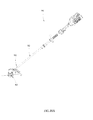
- a motor 621 has a driving shaft 622 for driving a head housing 612 and a one-way bearing 640 and a damping device 611 are provided.
- a driving device 620 includes the motor 621 .
- a trimming head 610 includes a spool 611 and the head housing 612 .
- a supporting element 650 is configured as a housing for accommodating the motor 621 .
- the one-way bearing 640 is disposed between the spool 611 and the supporting element 650 , so that the spool 511 can only rotate unidirectionally relative to the supporting element 650 .
- the driving shaft 622 passes through the spool 611 , but the spool 611 is not driven by the driving shaft 622 directly. That is, the torque is not transmitted directly between the driving shaft 622 and the spool 611 .
- the driving shaft 622 is connected fixedly with the head housing 612 , and the head housing 612 is driven by the head housing 612 directly. And then the spool 611 is driven by the head housing 612 through the transmission structure in FIG. 3B .
- the spool 611 and the head housing 612 can be rotated synchronously so as to perform the cutting mode.
- the motor 621 is rotated reversely, the spool 611 is rotated relative to the head housing 612 so as to perform the auto-winding mode.
- the damping device can not only apply a resistance force on the head housing to damp its rotation, but can also apply a resistance force on the spool to damp its rotation.
- the damping device can apply a resistance force both on the head housing and on the spool.
- more than one damping element can be disposed based on the embodiment in FIG. 6A , so that the head housing 612 can be damped and slowed down through contacting in the auto-winding mode.
- the damping device includes a first damping element and a second damping element.
- the first damping element can apply a first resistance force on the spool to damp its rotation.
- the second damping element can apply a second resistance force on the head housing to damp its rotation.
- the head housing can be rotated relative to the spool under the effect of the first resistance force and the second resistance force.
- a trimming head 810 includes a spool 811 and a head housing 812 which are similar to the spool and the head housing described previously.
- a driving shaft 822 is connected directly with the spool 811 so as to drive the spool 811 to rotate.
- the spool 811 and the head housing 812 are formed with transmission structures 811 a and 812 a respectively which can be engaged with each other.
- the transmission structures 811 a and 812 a are engaged with each other, so the head housing 812 is driven by the spool 811 to rotate together.
- the transmission structures 811 a and 812 a are disengaged from each other. At this moment, if the head housing 812 is damped, the spool 811 is rotated relative to the head housing 812 .
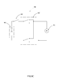
- an electromagnet 813 is provided, and a magnetic element 812 b is fastened on the head housing 812 .
- a supporting element 814 can be provided for mounting the electromagnet 813 .
- the supporting element 814 can be a guard of the grass trimmer, a housing of the motor or other parts connected fixedly with them.
- the electromagnet 813 When it is needed to perform the auto-winding mode, the electromagnet 813 is powered on to generate a magnetic field so as to attract the magnetic element 812 b . So, the axial position of the head housing 812 is changed. At this moment, the motor is controlled so as to make the driving shaft 822 drive the spool 811 , and a relative rotation is created between the spool 811 and the head housing 812 . While, when it is needed to perform the cutting mode, the electromagnet 813 does not generate the magnetic field, and the head housing 812 is moved in the axial direction so as to make the transmission structures 811 a and 812 a engage. Thus, the spool 811 and the head housing 812 are rotated synchronously.
- the magnetic element 812 b is an annular element.
- the electromagnet 813 is disposed at a corresponding position.
- a part of the head housing 812 can be made of magnetic material or metal material.
- a trimming head 810 ′ includes a rope, wire, cable, or the like 813 ′.
- the rope 813 ′ passes through a driving shaft 822 ′ directly, which is used to pull a head housing 812 ′ to change the position of the head housing 812 ′.
- a spool 811 ′ can be rotated relative to the head housing 812 ′.
- a trimming head 810 ′′ includes a rope 813 ′′ for pulling a head housing 812 ′′ from the top so as to change the position of the head housing 812 ′′.
- a spool 811 ′′ can be rotated relative to the head housing 812 ′′.
- the motor can be used to drive the head housing or the similar method can be used to change its position so as to realize the function above.
- a clutch device is provided for disengaging the spool and the head housing when it is needed. So, only one of the spool and the head housing is driven by the driving shaft, and the relative rotation is created between them. While, when the spool and the head housing are needed to rotate synchronously, they are engaged, so that one of them can drive the other.
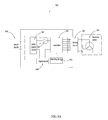
- a grass trimmer 900 includes a brushless motor 901 , a driving circuit 902 , a controller 903 , a detecting device 904 , a power supply circuit 905 and a power supply 906 .
- the brushless motor 901 includes three-phase windings with Y-type connection. Certainly, the three-phase windings can use triangular connection.
- the driving circuit 902 is used to drive the brushless motor 901 .
- the driving circuit 902 includes six semiconductor switches Q 1 -Q 6 which constitute a full-bridge circuit with six arms.
- the terminals of the windings of the brushless motor 901 are connected between two corresponding semiconductor switches of the driving circuit 902 .
- the semiconductor switches Q 1 -Q 6 can be driven by corresponding electrical signals so as to conduct the circuit at a certain duty cycle.
- the current passes the corresponding winding to drive the brushless motor 901 .
- the controlling signal can control the current of the brushless motor 901 through controlling the duty cycle of the semiconductor switches Q 1 -Q 6 so as to control the speed of the brushless motor 901 .
- the controller 903 is used to control the driving circuit 902 , and in particular to send controlling signals to the driving circuit 902 .
- the controller 903 can be constituted by a main chip mainly for operating and outputting signals and a driving chip mainly for sending driving signals to the driving circuit 902 .
- the main chip controls the driving circuit 902 through controlling the driving chip.
- the controller 903 can be constituted by one chip.
- the detecting device 904 includes a Hall sensor which including several Hall elements.
- the detecting device 904 can determine the speed of a rotor of the brushless motor 901 according to the signal change of the Hall elements.
- the detecting device 904 can detect the voltage and current of the windings of the brushless motor 901 and feedback to the controller 903 as the control basis of the controller 903 .
- the power supply circuit 905 is mainly used to adjust the voltage of the power supply 906 so that the controller 903 can obtain proper power supply.
- the power supply 906 is mainly used to supply power to the grass trimmer 900 .
- the power supply 906 is a battery device which can be charged repeatedly.
- a physical switch 907 can be disposed between the controller 903 and the power supply circuit 905 which can be controlled by the user to switch on or off the electric connection between the controller 903 and the power supply circuit 905 , so the controller 903 cannot drive the brushless motor 901 .
- the physical switch 907 can be acted as a main switch of the grass trimmer 900 , which is used for the user to control the start of the brushless motor 901 .
- a signal switch 908 can be provided.
- the signal switch 908 is able to be operated by the user to send different signals.
- the controller 903 can output different control modes according to the signals sent by the signal switch 908 , so that the brushless motor 901 has different running states.
- the signal switch 908 can be acted as an operating element for the user to choose the cutting mode or the auto-winding mode.
- the signal switch 908 sends a first signal.
- the user controls the physical switch 907 to power on the controller 903 .
- the controller 903 enters a first control mode according to the first signal received and outputs the driving signal to the driving circuit 902 so as to make the brushless motor 901 rotate forwardly at a high speed.
- the signal switch 908 sends a second signal which is different from the first signal.
- the controller 903 enters a second control mode according to the second signal and outputs the control signal so as to make the brushless motor 901 rotate reversely at a low speed.
- two physical switches or two signal switches can be used, which can be used to switch the modes and control the start of the brushless motor 901 respectively.
- the speed can be controlled by the duty cycle used for driving the driving circuit 902 when the controller 903 is in the first control mode and the second control mode.
- the controller 903 can output the driving signal at a high duty cycle in the first control mode, and output the driving signal at a low duty cycle in the second control mode.
- the current of the brushless motor 901 can be detected by the detecting device 904 .
- the controller 903 can determine whether the trimming line is tensioned according to a current threshold or a current slop threshold so as to make the brushless motor 901 in the auto-winding mode stop.
- a current threshold can be set to determine whether the winding is finished.
- the speed of the motor decreases due to the increase of the load.
- a speed threshold or a speed slop threshold can be set to determine whether the winding is finished.
- a position sensor or an optical sensor can be used to determine the position and state of the trimming line so as to finish the auto-winding mode.
- the controller 903 activates the auto-winding mode firstly. If a representation of the high load occurs, for example the large current or low speed, the controller 903 can determine that the auto-winding mode is not suitable for running at this moment. And then the brushless motor 901 is stopped to drive, and a sound signal or a light signal can be used to remind the user.
- a representation of the high load for example the large current or low speed
- the controller 903 can determine the load state of the brushless motor 901 according to the speed or current of the brushless motor 901 so as to determine when to stop the winding and whether the auto-winding mode is suitable currently.
- controller 903 can realize the controlling method as following:
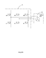
- the grass trimmer 900 includes a brush motor 901 ′.
- a toggle switch 902 ′ can be used to switch the connecting methods between the brush motor 901 ′ and a power supply 903 ′.
- a main switch 904 ′ can be operated to start the brush motor 901 ′.
- a difference between the grass trimmer 910 in FIG. 10A and the grass trimmer 500 in FIG. 5A is the position of the second operating element.
- the second operating element is disposed on the connecting rod assembly 912 and close to the trimming head 913 .
- a second operating element 921 of a grass trimmer 920 can be disposed on a first housing 922 .
- a second operating element 931 of a grass trimmer 930 can be disposed on a first housing 932 .
- the second operating element is disposed close to the trimming head, so that the user can start the auto-winding mode conveniently when the trimming line is inserted in the trimming head. Otherwise, the first operating element for starting the cutting mode is far from the second operating element, so that the user cannot touch the first operating element while the auto-winding is running. Similarly, the second operating element cannot be touched accidentally while the cutting mode is running.
- a grass trimmer 940 includes a spool 941 , a head housing 942 and line frame elements 943 .
- the spool 941 can be driven by a motor to rotate.
- the head housing 942 includes an upper cover 942 a and a lower cover 942 b which are detachable.
- the head housing 942 can be rotated relative to the spool 941 .
- the line frame elements 943 can be mounted on the head housing 942 , in particular on the upper cover 942 a in a detachable or undetachable method. When the line frame elements 943 are mounted on the upper cover 942 a , they can be rotated relative to the spool 941 .
- the line frame elements 943 when the line frame elements 943 are mounted on the upper cover 942 a , they can be rotated with the head housing 942 constituted by the upper cover 942 a and the lower cover 942 b synchronously, or with the upper cover 942 a when the lower cover 942 b is detached. Moreover, the line frame elements 943 can be mounted on other part which is able to rotate relative to the spool 941 .
- the line frame elements 943 are formed with line frame structures 943 a allowing the trimming line to pass through and connecting arms 943 b for connecting the line frame structures 943 a to make the line frame structures 943 a locate on the outside of the spool 941 .
- the connecting arms 943 b make the line frame structures 943 a locate on the outside of the spool 941 in a circumferential direction.
- the user can wind the trimming line without opening the head housing 942 , that is without separating the upper cover 942 a and the lower cover 942 b . It is similar to the line winding method described above.
- the trimming line can be passed through apertures 942 c of the head housing 942 . Because the line frame elements 943 cannot be rotated relative to the head housing 942 , the line frame structures 943 a can be aligned with the apertures 942 c . So, the trimming line can be passed through the line frame structures 943 a and then inserted into the spool 941 .
- the spool 941 is rotated relative to the apertures 942 c or the line frame structures 943 a so that the trimming line is wound on the spool 941 .
- the advantage is that the user can finish the line winding while not having to open the head housing 942 .
- the user also can realize the line winding in the method of opening the head housing 942 .
- the lower cover 942 b is opened to expose the spool 941 and the line frame elements 943 .
- the trimming line is passed through the line frame structures 943 a and inserted in the spool 941 .
- the grass trimmer can be operated so as to realize the relative rotation of the spool 941 and the line frame elements 943 . So, the trimming line passes through the line frame structures 943 a continuously and winds on the spool 941 .
- the lower cover 942 b can be mounted back.
- the advantage is that, it is easy for the user to observe the state of line winding and control according to the state of line winding.
- the line frame elements 943 can be omitted.
- a whole or a part of the head housing 942 can be made of transparent material, which can realize the object of observing the state of line winding as well.
- the line frame elements 943 can be a detachable attachment.
- the head housing 942 can be opened, and the lower cover 942 b can be separated.
- the line frame elements 943 are mounted on the upper cover 942 a or other part which is rotatable relative to the spool 941 , for example a housing 944 for accommodating the motor.
- the grass trimmer is passed through the line frame structures 943 a and inserted in the spool 941 .
- the spool 941 is driven to rotate.
- the line frame elements 943 can be driven.
- the trimming line can be wound on the spool 941 through the relative rotation between the spool 941 and the line frame elements 943 .
- the line frame elements 943 are detached, and the free ends of the trimming line can go out from the apertures 942 c of the lower cover 942 b .
- the lower cover 942 b is coupled with the upper cover 942 a , and the line winding is finished.
- the upper cover 942 a and the lower cover 942 b can be formed with a half of the apertures 942 c respectively.
- the whole apertures 942 c is formed. That is the upper cover 942 a and the lower cover 942 b are formed with two recesses respectively.
- the trimming line is located in the recesses of the upper cover 942 a or the lower cover 942 b , and then the upper cover 942 a and the lower cover 942 b are coupled as a whole.
- the trimming line can pass the apertures formed by the coupling of the upper cover 942 a and the lower cover 942 b . It is easy for the user to make the free ends of the trimming line go out of the head housing 942 from the inside.
- the advantage of the detachable line frame elements 943 is that, for the grass trimmer with the head housing 942 being capable of detaching entirely or partially, the spool 941 can be exposed through detaching the head housing 942 , and then the line frame elements 943 as an attachment is disposed (the line frame elements 943 may be not mounted on the head housing 942 but mounted on other part which is fixed relative to the motor, for example the housing of the motor or the guard). And then the spool 941 is driven at a low speed so as to realize the auto-winding. This can make the previous grass trimmer without auto-winding function have the corresponding hardware structure for auto-winding after the line frame elements 943 are disposed. Hence, the speed of the motor for driving the spool 941 should be adjusted so that the spool 941 is rotated at a low speed during auto-winding to ensure user safety.
- the line frame elements 943 are formed with the line frame structures 943 a .
- the line frame elements 943 can be rotated relative to the spool 941 .
- the line frame elements 943 are equivalent to simulating the manual winding of the user's hand
- the line frame structures 943 a are equivalent to the fingers for holding the trimming line.
- the line frame elements 943 can be defined as a line holding element for holding the trimming line so as to make the trimming line rotate relative to the spool.
- the line frame structures 943 a can be defined as a line holding structure which simulates the fingers to hold the trimming line at a location and allows the trimming line pass through the line frame structures 943 a continuously so as to wind on the spool 941 .
- a trimming head 940 ′ includes a spool 941 ′ and a head housing 942 ′, which is similar to the trimming head 940 in FIGS. 11A-11C .
- the difference is that the line frame elements 943 are replaced by the winding pins 943 ′.
- the head housing 942 ′ can be constituted by an upper cover 942 a ′ and a lower cover 942 b ′ which are detachable.
- the winding pins 943 ′ similar to the line frame elements 943 can be detachable or undetachable, which can be mounted on other part being capable of rotating relative to the spool 941 ′.
- the difference is that the winding pins 943 ′ are not formed with the line frame structures 943 a , but formed with concave parts 943 a ′.
- the concave parts 943 a ′ can locate the trimming line going around the concave parts 943 a ′.
- the winding pins 943 ′ When the winding pins 943 ′ are rotated relative to the spool 941 ′, they can drive the trimming line through the friction force so as to realize the auto-winding. So, the winding pins 943 ′ can be defined as a line holding element, and the concave parts 943 a ′ can be defined as a line holding structure.
- line frame elements 953 can be acted as functional attachments which are independent of a trimming head 950 .
- Line frame elements 953 include a fixing seat 953 c except line frame structures 953 a and connecting arms 953 b .
- the fixing seat 953 c is connected with the connecting arms 953 b .
- an upper cover 952 a and a lower cover 952 b of a head housing 952 are separated so as to expose a spool 951 .
- the trimming line is passed through the line frame structures 953 a and inserted into the spool 951 .
- a motor is started to drive the spool 951 .
- the spool 951 is rotated relative to the line frame elements 953 so as to realize the auto-winding.
- an auxiliary device such as a bracket can be used to fix the grass trimmer or the spool 951 , and an extra motor 954 is used to drive the line frame elements 953 to rotate relative to the spool 951 . So, the auto-winding is realized. In this embodiment, the requirements of configuration of the grass trimmer itself is reduced. The auto-winding can be realized through the line frame elements 953 acting as separate attachments or a combination of the line frame elements 953 and a corresponding driving device, as long as the head housing 952 can be opened. And it is no need to change the grass trimmer too much.
- a grass trimmer includes a trimming head 961 , a motor 962 and an energy storing device 963 .
- the motor 962 is used to drive the trimming head 961 to rotate so as to cut vegetation.
- the trimming head 961 includes a spool and a head housing. The spool is accommodated in the head housing.
- the detail structure of the trimming head 961 can refer to the trimming head 410 in FIGS. 4A-4D .
- the grass trimmer includes a housing 964 for accommodating the motor 962 .
- the motor 962 is an electric motor having a motor shaft 966 for outputting power.
- the grass trimmer has the function of auto-winding.
- the spool can be rotated relative to the head housing so that the trimming line winds on the spool automatically.
- the energy storing device 963 is able to drive one of the spool and the head housing to rotate relative to the other so as to realize the function of auto-winding.
- the motor 962 rotates to make the energy storing device 963 store energy. Then, the user can control the energy storing device 963 to release energy so as to realize the function of auto-winding.
- the energy storing device 963 is disposed within the housing 964 , which is mounted on the top of the motor 962 .
- the energy storing device 963 includes an elastic element 965 which is a coil spring.
- the coil spring is coupled with the motor shaft 966 on an end. When the motor shaft 966 is rotated, it drives the end of the coil spring to move in a direction indicated by an arrow 967 . And the other end of the coil spring is fixed. At this moment, the coil spring stores energy. When it is needed to realize the function of auto-winding, the coil spring retracts to drive the motor shaft 966 to rotate reversely.
- the motor shaft 966 is connected with the spool or the head housing, so one of the spool or the head housing is driven by the motor shaft 966 to rotate relative to the other. Thus, the function of auto-winding is realized.
- a method for controlling the grass trimmer in particular a method for controlling the grass trimmer to wind the trimming line based on the embodiments described above is illustrated as flowing.
- the grass trimmer at least includes the spool, the line holding element and the motor.
- the spool is used to mount the trimming line.
- the trimming line can be mounted on the spool in a winding method or other method such as storing.
- the main function of the line holding element is similar to the function of the fingers against the trimming line while winding the trimming line with hands. That is the line holding element produces a limiting effect to make the trimming line revolve (taking the spool as a reference) and allow the trimming line to pass the line holding element and wind on the spool.
- the motor can drive one of the spool and the line holding element, so that the line holding element simulates the relative motion pattern of the hand and the spool when mounting the trimming line manually. That is, the relative rotation is created between the spool and the line holding element.
- the line holding element can be constituted by a housing for accommodating the spool.
- the head housing can be acted as the line holding element.
- the control method includes: S 101 supplying power to the motor so as to produce a relative rotation between the spool and the line holding element. More specifically, the control method supplies power to the motor when the grass trimmer is operated by the user.
- the power supplied to the motor can be electric energy.
- the grass trimmer includes a controller and an operating element.
- the controller is used to control whether to supply power to the motor.
- the grass trimmer is controlled by the controller to supply power to the motor.
- the grass trimmer is controlled by the controller to stop supplying power to the motor.
- the grass trimmer includes another operating element.
- the grass trimmer is controlled by the controller to stop supplying power to the motor.
- the two different operating elements are needed to be pressed to make the grass trimmer supply power to the motor.
- the operating method includes: S 101 supplying power to the motor, S 102 determining whether the load slope of the motor is greater than a preset value, and S 103 stopping supplying power to the motor.
- the controller determines whether to stop supplying power to the motor according to the load slop of the motor (the slope in the present invention should be considered as including mathematic definition which indicates rising tendency such as the derivative).
- the load slope of the motor is greater than the preset value
- the grass trimmer is controlled automatically to stop supplying power to the motor.
- the load slope of the motor isn't greater than the preset value
- the grass trimmer is controlled to supply power to the motor continuously.
- the load state can be determined according to the speed or the speed slope of the motor. When the speed slope is less than a preset value, the controller stops supplying power to the motor.
- the current slope of the electric motor can be used to make a similar judgement control. Specifically, when the current slope of the electric motor is greater than a preset value, the controller stops supplying power to the motor.
- the control method can use a timing method.
- the control method includes: S 201 supplying power to the motor, S 202 starting timing, S 203 determining whether the time satisfies a preset time, and S 204 stopping supplying power to the motor. Specifically, when the grass trimmer is controlled by the controller to supply power to the motor, timing is started. When the time satisfies the preset time, the grass trimmer is controlled to stop supplying power to the motor. when the time does not satisfy the preset time, the grass trimmer is controlled to supply power to the motor continuously.
- the motor can be provided with different power so that the spool and the line holding element can rotate at a first relative speed and a second relative speed respectively.
- the speed of the motor can be changed, so the relative rotation speed between the spool and the line holding element can be changed.
- the relative rotation speed between the spool and the line holding element should be less than the rotation speed of the trimming line or the spool while the trimming line is cutting vegetation.
- the method mainly includes the following steps:
- the grass trimmer includes the spool for winding the trimming line, line holding element being formed with line holding structure allowing the trimming line to pass through and the motor being capable of driving one of the spool and the line holding element.
- the grass trimmer in this step can be the grass trimmer in the foregoing examples. It is noted that the line holding element is detachable.
- the trimming line is associated with the line holding element and inserted in the spool.
- associating the trimming line with the line holding element it is dependent on the specific form of the line holding element and the line holding structure, which can refer to the examples described above.
- inserting in the spool can be understood as inserting in the holes or apertures formed on the spool or other structure which can limit the ends of the trimming line to hold the trimming line thereon.
- This step can make both the spool and the line holding structure act on the trimming line so as to get ready to mount the trimming line.
- the user can start the motor through the operating element or an action activating the sensor disposed on the grass trimmer, so that the relative rotation is produced between the spool and the line holding element.
- the user can switch off the motor to make the spool and the line holding element be relatively static.
- the controller of the grass trimmer can be used to determine when to switch off the motor.
- the operating element disposed on the grass trimmer can be triggered to start the motor, and the motor can be switched off by triggering the operating element once again or by triggering another operating element.
Landscapes
- Life Sciences & Earth Sciences (AREA)
- Environmental Sciences (AREA)
- Harvester Elements (AREA)
Abstract
Description
- The present application claims the benefit of International Application Number PCT/CN2016/110351, filed on Dec. 16, 2016, through which this application also claims the benefit of Chinese Patent Application No. 201610044465.6, filed on Jan. 22, 2016, Chinese Patent application number 201610626524.0, filed on Aug. 1, 2016, and Chinese Patent application number 201610875071.5, filed on Oct. 7, 2016 in the SIPO (State Intellectual Property Office—Chinese Patent Office), each of which is incorporated herein by reference in its entirety.
- The present disclosure relates generally to grass trimmers and, more particularly, to a grass trimmer having an auto-winding mode, an operating method thereof and a control method thereof.
- Grass trimmers are a kind of gardening tools, which are used to trim the lawn. The grass trimmer includes a trimming head. The trimming head rotates at high speed to drive a trimming line mounted thereon to rotate so as to realize the cutting function.
- The trimming head includes a spool allowing the trimming line to wind thereon. During the cutting operation, the trimming line is worn away gradually due to wear. After operating for a period, it is needed to change a new trimming line and wind the new trimming line around the spool. For the currently known trimming line, a user needs to rotate the spool manually to wind the trimming line around the spool. The winding operation is inconvenient and the winding speed is slow.
- The statements in this section merely provide background information related to the present disclosure and may not constitute prior art.
- In one aspect of the disclosure, a grass trimmer is provided. The grass trimmer includes a trimming head, a driving device for driving the trimming head to rotate so as to cut vegetation and an operating device for a user to operate so as to control the driving device. The trimming head includes a spool and a line holding element, the spool is used to wind a trimming line, and the line holding element is formed with a line holding structure allowing the trimming line to pass or bypass. The driving device includes a motor, the grass trimmer has an auto-winding mode, in the auto-winding mode, the motor drives at least one of the spool and the line holding element to make the spool and the line holding element rotate relatively so that the trimming line is wound on the spool automatically.
- In another aspect of the disclosure, an operating method for winding a trimming line of a grass trimmer is disclosed. The operating method includes:
- providing the grass trimmer, the grass trimmer including a spool allowing the trimming line to be wound thereon, a line holding element being formed with a line holding structure, and a motor being capable of driving at least one of the spool and the line holding element;
- associating the trimming line with the line holding element and inserting the trimming line in the spool; and
- starting the motor to make the spool and the line holding element rotate relatively.
- In another aspect of the disclosure, an operating method for winding a trimming line of a grass trimmer is disclosed. The operating method includes:
- associating the trimming line with a line holding element disposed on the grass trimmer and inserting the trimming line in a spool disposed on the grass trimmer; and
- starting a motor to make the spool and the line holding element rotate relatively.
- In another aspect of the disclosure, a control method for winding a trimming line of a grass trimmer is disclosed. The grass trimmer includes a spool allowing the trimming line to be wound thereon, a line holding element being formed with a line holding structure for holding the trimming line and a motor being capable of driving at least one of the spool and the line holding element to make the spool and the line holding element rotate relatively. The control method includes supplying power to the motor to make the spool and the line holding element rotate relatively.
- Further areas of applicability will become apparent from the description provided herein. It should be understood that the description and specific examples are intended for purposes of illustration only and are not intended to limit the scope of the present disclosure.
-
FIG. 1A is a schematic view of an exemplary grass trimmer. -
FIG. 1B a schematic view showing the structure of a part of the grass trimmer inFIG. 1A . -
FIG. 1C is an exploded view of the structure inFIG. 1B . -
FIG. 1D is a schematic view showing the transmission of a spool and a head housing inFIG. 1B . -
FIG. 2A is an exploded view of an exemplary trimming head and an exemplary damping device. -
FIG. 2B is a section view of the trimming head and the damping device inFIG. 2A . -
FIG. 3A is also a schematic view of an exemplary trimming head and an exemplary damping device. -
FIG. 3B is a schematic view showing the transmission of a spool and a head housing inFIG. 3A . -
FIG. 4A is also a schematic view of an exemplary grass trimmer. -
FIG. 4B is a schematic view showing the structure of a part of the grass trimmer inFIG. 4A . -
FIG. 4C is a section view of the structure inFIG. 4B . -
FIG. 4D is an exploded view of the structure inFIG. 4B . -
FIG. 4E is another exploded view of the structure inFIG. 4B . -
FIG. 4F is a section view of an upper cover inFIG. 4E . -
FIG. 4G is a section view of a spool inFIG. 4E . -
FIG. 4H is a schematic view showing the inserting method of a trimming head inFIG. 4A . -
FIG. 4I is a schematic view of an operating device inFIG. 4A . -
FIG. 4J is another schematic view of the operating device inFIG. 4A , wherein a first operating element and a second operating element are in a first preset operating state and a second preset operating state respectively. -
FIG. 4K is a schematic view of an operating device. -
FIG. 4L is a schematic view showing a second operating element of the operating device inFIG. 4K , wherein the second operating element is in a second position. -
FIG. 4M is a schematic view of a line breaking device. -
FIG. 5A is also a schematic view of an exemplary grass trimmer. -
FIG. 5B is a schematic view of a trimming head and a first housing of the grass trimmer inFIG. 5A . -
FIG. 5C is a schematic view of the trimming head and the first housing inFIG. 5B , wherein the trimming head and the first housing are separated. -
FIG. 5D is an exploded view of the structure inFIG. 5B . -
FIG. 5E is another exploded view of the structure inFIG. 5B . -
FIG. 5F is a plane view of the structure inFIG. 5B . -
FIG. 5G is a sectional view of the structure cut along line A-A inFIG. 5F . -
FIG. 5H is a schematic view of a spool and a positioning element inFIG. 5D . -
FIG. 5I is a schematic view of a lower cover inFIG. 5D . -
FIG. 5J is a schematic view of the trimming head inFIG. 5F , wherein the trimming head is moved upwardly relative to the first housing. -
FIG. 5K is a sectional view of the structure cut along line B-B inFIG. 5J . -
FIG. 5L is a schematic view of a damping device inFIG. 5A . -
FIG. 5M is a schematic view of the first housing and a driving shaft inFIG. 5C . -
FIG. 5N is a sectional view of the structure cut along line C-C inFIG. 5M . -
FIG. 5O is an exploded view of the damping device inFIG. 5A . -
FIG. 5P is a plane view of the damping device inFIG. 5A , wherein a stopping element of the damping device is at a stopping position. -
FIG. 5Q is a sectional view of the structure cut along line D-D inFIG. 5P . -
FIG. 6A is a schematic view of a trimming head, a motor and a damping device. -
FIG. 7A is a schematic view of an electric magnet and a trimming head. -
FIG. 7B is a schematic view of a head housing inFIG. 7A , wherein the head housing is moved relative to a spool. -
FIG. 8A is a schematic view of a head housing, wherein the head housing can be pulled by a rope. -
FIG. 8B is a schematic view of the head housing inFIG. 8a , wherein the head housing is moved relative to a spool. -
FIG. 8C is another schematic view of a head housing, wherein the head housing can be pulled by a rope. -
FIG. 8D is a schematic view of the head housing inFIG. 8C , wherein the head housing is moved relative to a spool. -
FIG. 9A is a circuit block diagram of a grass trimmer using a brushless motor. -
FIG. 9B is a schematic view of a driving circuit inFIG. 9A . -
FIG. 9C is a circuit block diagram of a grass trimmer using a brush motor. -
FIG. 10A is a schematic view of the second operating element disposed on a connecting rod assembly. -
FIG. 10B is a schematic view of the second operating element disposed on the first housing. -
FIG. 10C is a schematic view of the second operating element disposed on a guard. -
FIG. 11A is a schematic view of a grass trimmer having a line holding element. -
FIG. 11B is a schematic view of a head housing and a spool of the grass trimmer inFIG. 11A , wherein the head housing and the spool are separated. -
FIG. 11C is a plane view of the structure inFIG. 11A . -
FIG. 11D is a schematic view of an exemplary line holding element. -
FIG. 12A is a schematic view of a trimming head and a line holding element acted as an attachment. -
FIG. 12B is a schematic view of the line holding element inFIG. 12A , wherein the line holding element is in a working state. -
FIG. 12C is a schematic view of a line frame element, wherein the line frame element is driven by a motor. -
FIG. 13A is a schematic view of an energy storing device, a motor and a trimming head. -
FIG. 13B is an enlarged view of a part of the structure inFIG. 13A . -
FIG. 14A is a flow diagram showing a control method for controlling winding of a grass trimmer. -
FIG. 14B is another flow diagram showing a control method for winding of a grass trimmer. -
FIG. 14C is a flow diagram showing an operating method for winding of a grass trimmer - The drawings described herein are for illustrative purposes only of selected embodiments and not all possible implementations, and are not intended to limit the scope of the present disclosure. Corresponding reference numerals indicate corresponding parts throughout the several views of the drawings.
- The following description is merely exemplary in nature and is in no way intended to limit the scope of the invention hereinafter claimed, its application, or uses.
- Referring to
FIGS. 1A-1C , agrass trimmer 100 includes a trimminghead 110, adriving device 120 and anoperating device 130. - The trimming
head 110 is configured to mount and accommodate atrimming line 101. Thetrimming line 101 is partially accommodated in the trimminghead 110. Thetrimming line 101 has a part extending out of the trimminghead 110 which is used to cut vegetation when the trimminghead 110 is rotated. - The
driving device 120 is able to drive the trimminghead 110 to rotate about anaxis 110 a so as to cut vegetation. The operatingdevice 130 is used for a user to control thegrass trimmer 100. - Specifically, the driving
device 120 includes amotor 121 and a drivingshaft 122. The drivingshaft 122 is connected with the trimminghead 110 so as to drive the trimminghead 110 to rotate. - The
grass trimmer 100 further includes afirst housing 150, asecond housing 160 and abattery pack 170. Thefirst housing 150 is configured to mount and accommodate themotor 121. Thebattery pack 170 acting as a power source at least can supply power to thegrass trimmer 100. Thesecond housing 160 is configured to engage with thebattery pack 170 detachably. - A circuit board is accommodated in the
second housing 160, which is connected with themotor 121 electrically so that thebattery pack 170 can supply power to themotor 121 and control themotor 121. Thefirst housing 150 and thesecond housing 160 are connected with each other through a connectingrod assembly 190. The operatingdevice 130 is fixedly mounted on the connectingrod assembly 190. Thegrass trimmer 100 further includes anauxiliary handle 191 for the user to grip which is fixedly mounted on the connectingrod assembly 190. - The
trimmer head 110 includes aspool 111 and ahead housing 112. Thespool 111 is accommodated in thehead housing 112 for winding thetrimming line 101. Thespool 111 is formed with aninner aperture 111 a. Thehead housing 112 is formed with anouter aperture 112 a. As an example, thehead housing 112 includes anupper cover 112 b and alower cover 112 c, so that thehead housing 112 is easy to assemble with thespool 111 and it is easy for the user to open thehead housing 112 to check the inside of thehead housing 112. - The
trimmer head 110 includes aspring 113 which can apply a force between thehead housing 112 and thespool 111. The force applied by thespring 113 makes thespool 111 depart from thelower cover 112 c. - When it is needed to mount a
new trimming line 101, theinner aperture 111 a and theouter aperture 112 a are aligned, and then thetrimming line 101 is passed through theouter aperture 112 a and entered into theinner aperture 111 a. At this moment, as long as thespool 111 is moved relative to thehead housing 112, thetrimming line 101 can be wound on thespool 111 under the limiting action of theouter aperture 112 a. The drivingshaft 122 is connected with thehead housing 112, which can drive thespool 111 to rotate about theaxis 110 a directly. - The
spool 111 is connected rotatably with thehead housing 112, which can rotate relative to thehead housing 112. Meanwhile, thehead housing 112 is able to move relative to thespool 111 in a direction parallel to theaxis 110 a. - As shown in
FIG. 1D , thespool 111 is provided with a firstcircumferential structure 111 b, and thehead housing 112 is provided with a secondcircumferential structure 112 d. Under the action of thespring 113, thespool 111 can move upward so that the firstcircumferential structure 111 b is engaged with the secondcircumferential structure 112 d. Thus, thespool 111 can be rotated synchronously with thehead housing 112. It is noted that, the firstcircumferential structure 111 b and the secondcircumferential structure 112 d have a transmitting surface therebetween which is obliquely inclined with theaxis 110 a. - When the first
circumferential structure 111 b and the secondcircumferential structure 112 d are engaged with each other, the user can start themotor 121 to make thegrass trimmer 100 be in a cutting mode. At this moment, if thetrimming line 101 wound on thespool 111 is sufficiently long, a part of thetrimming line 101 exposed out of thehead housing 112 can cut the vegetation in a whipping action. - Referring to
FIGS. 1B-1C , thegrass trimmer 100 further includes a dampingdevice 140. Specifically, the dampingdevice 140 includes afriction element 141. Thefriction element 141 is connected slidably with thefirst housing 150 and can move along a direction A. When thefriction element 141 is moved to contact with thehead housing 112, thehead housing 112 tends to rotate relative to thespool 111. As the friction increases, a component force in the direction of theaxis 110 a is acted on thehead housing 112 due to the inclined transmitting surface between the firstcircumferential structure 111 b and the secondcircumferential structure 112 d. The component force can overcome the spring force of thespring 113 sufficiently to make thehead housing 112 move upward, so that the firstcircumferential structure 111 b is disengaged with the secondcircumferential structure 112 d. Thus, thespool 111 can rotate relative to thehead housing 112, and thegrass trimmer 100 is in an auto-winding mode. In the auto-winding mode, thespool 111 driven by themotor 121 can rotate relative to thehead housing 112 under the action of thefriction element 141 so as to realize an auto-winding function. - However, when the
spool 111 is wound withenough trimming line 101 and the part of thetrimming line 101 exposed out of the head housing is not long enough to cut the vegetation, thespool 111 can rotate relative to thehead housing 112 so as to feed thetrimming line 101 automatically for cutting purposes. - In this embodiment, the function of the
friction element 141 is to produce damping on thehead housing 112 so as to slow down thehead housing 112. Thus, the relative rotation is occurred between thehead housing 112 and thespool 111. The user can operate thefriction element 141 directly or indirectly to switch thegrass trimmer 100 between the cutting mode and the auto-winding mode. However, the user can operate thefriction element 141 in a status corresponding to the desired mode firstly, and then start themotor 121. - Referring to
FIGS. 2A-2B , a trimminghead 210 which is similar to the trimminghead 110 includes aspool 211 and ahead housing 212. Thespool 211 and thehead housing 212 are similar to thespool 111 and thehead housing 112 inFIGS. 1-3 . Thehead housing 212 includes anupper cover 212 a and alower cover 212 b. - A difference between this example and the prior example is that a damping
device 240 inFIGS. 2A-2B includes astop pin 241 for stopping thehead housing 212 rotating wherein thehead housing 212 is formed with astop recess 212 c for engaging with thestop pin 241. Specifically, thestop recess 212 c is disposed on theupper cover 212 a. In the auto-winding mode, thestop pin 241 is inserted in thestop recess 212 c so that thehead housing 212 is stopped from rotating relative the grass trimmer. As the principle described above, the relative rotation between thespool 211 and thehead housing 212 can realize the function of auto-winding. - The function of the
stop pin 241 is also to damp the rotation of thehead housing 212. The difference is that, the damping function of thefriction element 141 is to slow down, and the damping function of thestop pin 241 is to limit the movement. Here, slowing down and limiting movement are both defined as damping. Both thefriction element 141 and thestop pin 241 can be considered as a kind of the damping device. - Referring to
FIGS. 3A-3B , a trimminghead 310 can be driven to rotate about anaxis 310 a. Specifically, the trimminghead 310 includes aspool 311 and ahead housing 312. Thehead housing 312 is formed with anouter aperture 312 a allowing a trimming line to pass through. Thespool 311 is formed with aninner aperture 311 a. - In this example, a one-
way bearing 340 and a supportingelement 350 are provided. The one-way bearing 340 allows two elements or two parts connected therewith to be able to rotate relatively in one direction, but does not allow them to rotate relatively in another direction. The supportingelement 350 is connected rotatably with a part of the trimminghead 310 and can support the trimminghead 310 rotatably. The supportingelement 350 may be a first housing for accommodating a motor or a component connected with the first housing fixedly, for example a trimming guard. - More specifically, the one-
way bearing 340 is disposed between the supportingelement 350 and thehead housing 312, so that the supportingelement 350 is able to rotate unidirectionally relative to thehead housing 312. Taking the supportingelement 350 as a reference, thehead housing 312 can rotate in one direction and cannot rotate in another direction. - A driving
shaft 322 is connected fixedly with thespool 311, so that thespool 311 can rotate relative to the supportingelement 350 in two directions. Taking the supportingelement 350 as a reference, thespool 311 can rotate forwardly and reversely. - Similar to the foregoing examples, the
spool 311 is provided with a firstcircumferential structure 311 a, and thehead housing 312 is provided with a secondcircumferential structure 312 a which is able to engage with the firstcircumferential structure 311 a. The difference is that at least one of the transmitting surfaces of the firstcircumferential structure 311 a and the secondcircumferential structure 312 a is substantially parallel to theaxis 310 a. Thus, when the firstcircumferential structure 311 a and the secondcircumferential structure 312 a are rotated in a direction, they cannot disengage with each other. - Based on the arrangement described above, when the motor is rotated in a forward direction, the
spool 311 is driven by the drivingshaft 322 to rotate forwardly. At this moment, the torque is transmitted through the transmitting surfaces of the firstcircumferential structure 311 a and the secondcircumferential structure 312 a which are substantially parallel to theaxis 310 a. Meanwhile, the one-way bearing 340 allows thehead housing 312 to be able to rotate forwardly relative to the supportingelement 350, i.e. the grass trimmer. So, thespool 311 is rotated synchronously with thehead housing 312, and the grass trimmer performs the cutting mode. When the motor is rotated in a reverse direction, thespool 311 is driven by the drivingshaft 322 to rotate reversely. Thehead housing 312 is stopped from rotating reversely by the one-way bearing 340, so that a relative rotation is created between thespool 311 and thehead housing 312. At this moment, the firstcircumferential structure 311 a and the secondcircumferential structure 312 a are disengaged with each other because their contacting surfaces are inclined surfaces. The firstcircumferential structure 311 a and the secondcircumferential structure 312 a cannot stop the relative rotation between thespool 311 and thehead housing 312 thoroughly, so the relative rotation is created continuously and the grass trimmer performs the auto-winding mode. - The function of the one-
way bearing 340 is similar to thestop pin 241 which is to stop thehead housing 312 from rotating. So, the one-way bearing 340 can be considered as a kind of the damping device. The difference in the examples is that thefriction element 141 and thestop pin 241 are needed to be operated or activated whereas the one-way bearing 340 can realize the damping function in response to a change in the driving direction of the motor. Thereby, the mechanical structure for activating the auto-winding mode is simplified. The auto-winding mode and the cutting mode can be switched therebetween by means of controlling the forward and reverse rotation of the motor. - In short, the trimming
head 310 is driven by the motor around the rotateaxis 310 a, and the grass trimmer has the cutting mode, the auto-winding mode, and a release mode (feeding mode) shifted therebetween by use of first and secondcircumferential structures way bearing 340. - When the grass trimmer works in the cutting mode, the motor rotates in the first direction, and drives the
spool 311 to rotate along with thehead housing 312 by engagement or coupling between the first and secondcircumferential structures - When the grass trimmer is shifted to be in the feeding mode, the motor rotates in the first direction to drive the rotation of the trimming head or
spool 311. During the rotation of the trimming head orspool 311, the trimminghead 310 is knocked thereon so that thespool 311 and thehead housing 312 may be decoupled from each other by a spring element, such as shown inFIGS. 2a and 2b , to generate a relative rotation therebetween, thereby releasing the trimming line from thespool 311. - When the grass trimmer is shifted to be in the auto-winding mode, the motor rotates in the second direction opposite to the first direction, and drives the
spool 311 to rotate relative to thehead housing 312 by the disengagement of the first and secondcircumferential structures way bearing 340, the head housing or thewire holding member 312 is fixed to the motor case through the damper or one-way bearing device 340, and the head housing or thewire holding member 312 cannot be rotated, so that thespool 311 and thewire holding member 312 can maintain a relative rotation relationship therebetween, thereby automatically winding at least a part of the trimming line around thespool 311, which is being driven by the motor. - In a first example, an auto-winding method is provided for a grass trimmer, with the grass trimmer including a motor configured for driving a spool, the method comprises the steps of:
- a) providing a trimming head with the spool included within a head housing, the head housing having a first housing side and a second housing side;
b) inserting a trimming line, through the head housing from a first housing side, to enable the trimming line to be coupled to the spool; and
c) driving the spool to rotate relative to the head housing, thereby automatically winding at least a part of the trimming line around the spool.
Thus, a product of the auto-winding method for a grass trimmer of the first example can be achieved. - In a second example, a product of another auto-winding method for a grass trimmer can be also employed to automatically wind at least a part of the trimming line onto or around the spool.
- The auto-winding method for the grass trimmer of this second embodiment comprises the steps of:
- a) providing a trimming head with a spool to which a trimmer line is coupled;
- b) providing a motor configured for driving the spool; and
- c) activating the motor to drive the spool to enable at least a part of the trimming line to be wound around the spool.
- In a third example, the grass trimmer including a motor or driving device configured for driving a spool, the auto-winding method for the grass trimmer comprising the steps of:
- a) providing a trimming head with the spool to which a trimmer line is coupled;
- b) driving the spool to enable at least a part of the trimming line to be wound around the spool.
- It should be noted that the motor or driving device can be activated before or after the trimming line is coupled to the spool in the third example.
- Referring to
FIGS. 4A-4C , agrass trimmer 400 includes a trimminghead 410, adriving device 420 and anoperating device 430. - The trimming
head 410 is configured to mount and accommodate atrimming line 401. Thetrimming line 401 is partially accommodated in the trimminghead 410. Thetrimming line 401 has a part extending out of the trimminghead 410 which is used to cut vegetation when the trimminghead 410 is rotated. - The trimming
head 410 can be driven by the drivingdevice 420 to rotate about anaxis 410 a so as to drive the trimmingline 401 to cut vegetation. The operatingdevice 430 is used for the user to operate so as to control thegrass trimmer 400. - Specifically, the driving
device 420 includes amotor 421 and a drivingshaft 422. The drivingshaft 422 is connected fixedly with the trimminghead 410 so as to drive the trimminghead 410 to rotate. - The
grass trimmer 400 further includes afirst housing 450, asecond housing 460 and abattery pack 470. Thefirst housing 450 is configured to mount and accommodate themotor 421. Thebattery pack 470 acting as a power source at least can supply power to themotor 421 of thegrass trimmer 400. Thesecond housing 460 is configured to engage with thebattery pack 470 detachably. - A circuit board is accommodated in the
second housing 460, which is connected with themotor 421 electrically so that thebattery pack 470 can supply power to themotor 421 and control themotor 421. Thefirst housing 450 and thesecond housing 460 are connected with each other through a connectingrod assembly 490. The operatingdevice 430 is fixedly mounted on the connectingrod assembly 490. Thegrass trimmer 400 further includes anauxiliary handle 491 for the user to grip which is fixedly mounted on the connectingrod assembly 490. - The
trimming line 401 is mounted on the trimminghead 410. Aguard 480 is used to prevent thetrimming line 401 from hurting the user, so that it can realize the function of safety and protection. - Referring to
FIGS. 4C-4H , the trimminghead 410 includes aspool 411 and ahead housing 412. - The
spool 411 for winding thetrimming line 401 is connected with the drivingshaft 422 and can be driven by the drivingshaft 422 to rotate about theaxis 410 a. - The
head housing 412 includes anupper cover 412 a and alower cover 412 b. The trimminghead 410 further includes afan 412 c. Thefan 412 c includes blades for generating airflow. Thefan 412 c can be driven by themotor 421 to rotate so as to generate airflow. - In the embodiment in
FIGS. 4A-4E , a one-way bearing 440 acting as a damping device is used. The function of the one-way bearing 440 is to make thehead housing 412 connect with themotor 421 in a unidirectional rotary way. Specifically, a supportingelement 452 is connected with themotor 421, which allows the drivingshaft 422 to pass through. The supportingelement 452 is formed with a projectingportion 452 a for supporting an inner ring of the one-way bearing 440. The one-way bearing 440 is not connected with thehead housing 412 directly, but connected between the supportingelement 452 and thefan 412 c. So, thefan 412 c is only able to rotate unidirectionally relative to the supportingelement 452. Because thefan 412 c is connected with thehead housing 412 fixedly, thehead housing 412 is only able to rotate unidirectionally relative to the supportingelement 452 as well. - The
upper cover 412 a is formed with first connectingteeth 412 d. Thefan 412 c is formed with second connectingteeth 412 e for engaging with the first connectingteeth 412 d. Through the engagement between the first connectingteeth 412 d and the second connectingteeth 412 e, theupper cover 412 a can be rotated with thefan 412 c synchronously. The engagement between the first connectingteeth 412 d and the second connectingteeth 412 e can provide a guiding effect, so that thehead housing 412 is able to slide relative to thefan 412 c along theaxis 410 a and thefan 412 c is able to rotate about theaxis 410 a together with thehead housing 412. That is thefan 412 c is connected with thehead housing 412 fixedly. - The
grass trimmer 400 further includes aguard 451 fastened to thefirst housing 450. Theguard 451 is able to cover the blades of thefan 412 c in a radial direction of theaxis 410 a so as to prevent grass clippings from winding on thefan 412 c. And theguard 451 is able to change the direction of the airflow of thefan 412 c, so that the airflow generated by thefan 412 c can blow the grass clippings outward along the radial direction of theaxis 410 a. - The
spool 411 is driven directly by the drivingshaft 422 to rotate. Thehead housing 412 can rotate relative to thespool 411 and slide relative to thespool 411 in the direction of theaxis 410 a. - Referring to
FIGS. 4D-4G , thespool 411 is formed with first engaging teeth 411 a on the upper portion and secondengaging teeth 411 b on the lower portion. Thehead housing 412 is formed with first matchingteeth 412 f andsecond matching teeth 412 g therein. Specifically, thefirst matching teeth 412 f is formed on theupper cover 412 a, and thesecond matching teeth 412 g is formed on thelower cover 412 b. - When the
head housing 412 is at a first axial position relative to thespool 411, thefirst matching teeth 412 f are engaged with the first engaging teeth 411 a. So, when thespool 411 is rotated, it can drive thehead housing 412 to rotate synchronously. Specifically, the transmitting surfaces of thefirst matching teeth 412 f and the first engaging teeth 411 a are inclined surfaces, so that thefirst matching teeth 412 f and the first engaging teeth 411 a only can rotate together unidirectionally. When thespool 411 is rotated reversely, thespool 411 rotates relative to thehead housing 412 due to the skid between the inclined surfaces. - When the
head housing 412 is at a second axial position relative to thespool 411, the secondengaging teeth 411 b is engaged with thesecond matching teeth 412 g. Because the transmitting surfaces of the secondengaging teeth 411 b and thesecond matching teeth 412 g are inclined surfaces, the skid can occur between the secondengaging teeth 411 b and thesecond matching teeth 412 g. So, when thehead housing 412 is at the second axial position relative to thespool 411, thehead housing 412 cannot be driven by thespool 411 completely. Thehead housing 412 still can rotate relative to thespool 411, but the speed difference of the relative rotation is decreased by the engagement of the secondengaging teeth 411 b and thesecond matching teeth 412 g. - The trimming
head 410 includes aspring 410 b. Thespring 410 b can generate a force acting between thelower cover 412 b and thespool 411, so that thehead housing 412 is biased to the axial position and can rotate with thespool 411 synchronously. That is the first axial position described above. - The trimming
head 410 further includes a first contactingelement 410 c and a second contactingelement 410 d. Thespring 410 b is disposed between the first contactingelement 410 c and the second contactingelement 410 d and can act on the first contactingelement 410 c and the second contactingelement 410 d directly. The first contactingelement 410 c and the second contactingelement 410 d can prevent thespring 410 b from wearing on thespool 411 and thehead housing 412, which are made of metal. - The trimming
head 410 further includes abutton 410 e which is connected rotatably with thelower cover 412 b. A bearing 410 f is disposed between thebutton 410 e and thelower cover 412 b, so that thebutton 410 e can be rotated relative to thelower cover 412 b. Meanwhile, thebutton 410 e and thelower cover 412 b can move together in the direction of theaxis 410 a. When the position of thebutton 410 e is changed, thelower cover 412 b can move therewith. That is, the axial position of thehead housing 412 can be changed when thebutton 410 e is bumped. - When the
grass trimmer 400 is in the cutting mode, the user can bump the trimminghead 410, and thebutton 410 e contacts with the ground to make thehead housing 412 slide, so that the first engaging teeth 411 a is disengaged with thefirst matching teeth 410 f and rotated relative to thefirst matching teeth 410 f. Further, when thebutton 410 e is bumped, thehead housing 412 can slide to the second axial position relative thespool 411 and rotate at a lower speed relative to thespool 411. So, thetrimmer line 401 wound on thespool 411 can be fed out of thehead housing 412 partially, and thegrass trimmer 400 performs a line feeding mode. This arrangement has advantages that is, when themotor 421 is rotated at a speed in the cutting mode, the relative rotation speed of thehead housing 412 and thespool 411 is controlled, so that thetrimmer line 401 cannot be fed excessively during each bumping. - The
button 410 e is able to rotate freely relative to thelower cover 412 b under the action of thebearing 410 f, so that the wearing of thetrimmer head 410 is reduced. Thespring 410 b can generate a force acting on thehead housing 412 so as to make thehead housing 412 move downwardly relative to thespool 411. Ananti-vibration element 410 g is disposed between theupper cover 412 e and thespool 411 for reducing the impact between theupper cover 412 e and thespool 411. Specifically, theanti-vibration element 410 g is a rubber washer. - The
spool 411 is formed with aninner aperture 411 c and thehead housing 412 is formed with anouter aperture 412 h allowing thetrimming line 401 to pass from the inside to the outside of thehead housing 412. When the cutting mode is finished, theinner aperture 411 c and theouter aperture 412 h are aligned automatically in the circumferential direction. Or, when the trimming line 40 a is not mounted on the trimminghead 410 and themotor 421 is stopped, theinner aperture 411 c and theouter aperture 412 h are aligned automatically in the circumferential direction. - The
spool 411 is formed with severalinner apertures 411 c, and the number of theinner apertures 411 c is even. The severalinner apertures 411 c are distributed uniformly in the circumferential direction of theaxis 410 e. Specifically, the number of the first engaging teeth 411 a is corresponded with the number of theinner apertures 411 c. Similarly, the number of the secondengaging teeth 411 b is corresponded with the number of theinner apertures 411 c. Thespool 411 is formed with sixinner apertures 411 c. Thespool 411 is further formed with six first engaging teeth 411 a and six secondengaging teeth 411 b. - The
spool 411 is formed with a guidingopening 411 d for guiding thetrimming line 401 to enter theinner apertures 411 c. The guidingopening 411 d is expanded gradually along the radial direction of the rotating axis of thespool 411. The first engaging teeth 411 a are formed with inclined surfaces. - The guiding
opening 411 d has a maximum size L1 in the circumferential direction of theaxis 410 a which is greater than a maximum size L2 between two adjacent first engaging teeth 411 a in the circumferential direction of theaxis 410 a. - When the
grass trimmer 400 is in the cutting mode, the transmitting surfaces of the first engaging teeth 411 a and thefirst matching teeth 412 f are so arranged that theouter apertures 412 h and theinner apertures 411 c can be aligned automatically in the circumferential direction when themotor 421 is stopped. Here, the word “align” means that thetrimming line 401 passing through theouter apertures 412 h can be guided into theinner apertures 411 c directly. - The
spool 411 is formed with afirst flange 411 e and asecond flange 411 f on its two ends. Thespool 411 is further formed with adivision plate 411 g in the middle portion. A first winding portion for winding and accommodating thetrimmer line 401 is formed between thefirst flange 411 e and thedivision plate 411 g. A second winding portion for winding and accommodating thetrimmer line 401 is formed between thesecond flange 411 f and thedivision plate 411 g. - In the cutting mode, the
spool 411 is driven by the drivingshaft 422 to rotate, and theupper cover 412 a is driven by thespool 411 to rotate. Thefan 412 c is driven by theupper cover 412 a to rotate. Thefan 412 c can rotate relative to thesecond housing 460 in a first direction referring to an arrow B inFIG. 4b . At this moment, themotor 421 is rotated forwardly so as to drive thespool 411 and thehead housing 412 to rotate in the first direction. - As shown in
FIG. 4h , when it is needed to supplement thetrimming line 401, two ends of thetrimming line 401 can be passed through the oppositeouter apertures 412 h of thehead housing 412 respectively, and then the two ends of thetrimming line 401 are extended into the two oppositeinner apertures 411 c of thespool 411 respectively. Sure, the user can insert two trimminglines 401 into the twoinner apertures 411 c respectively. At this moment, the user can control thegrass trimmer 400 to make it perform the auto-winding mode. Themotor 421 is rotated reversely so as to drive thespool 411 to rotate in a second direction opposite to the first direction. Due to the effect of the one-way bearing 440, thefan 412 c cannot rotate in the second direction. Thefan 412 c is connected with thehead housing 412 through the first connectingteeth 412 d and the second connectingteeth 412 e, so thehead housing 412 cannot rotate in the second direction. Thespool 411 is driven by the drivingshaft 422 to rotate relative to thehead housing 412 in the second direction so as to realize the auto-winding function. - Otherwise, the first engaging teeth 411 a, the second
engaging teeth 411 b, thefirst matching teeth 410 f and thesecond matching teeth 410 g are inclined teeth. The inclined surfaces of the inclined teeth cannot stop thespool 411 rotating relative to thehead housing 412. - When the
spool 411 is wound withenough trimming line 401, theexcess trimming line 401 which has not been wound needs to be to cut off. Referring toFIGS. 4A and 4H , thegrass trimmer 400 includes aline breaking device 481 for cutting off thetrimming line 401 automatically in the auto-winding mode. - The
line breaking device 481 includes aline breaking element 482. The trimminghead 410 can rotate relative to theline breaking element 482. Theline breaking element 482 is fastened to theguard 480. In the auto-winding mode, thetrimming line 401 can be driven by the trimminghead 410 to pass theline breaking element 482. When thetrimming line 401 is tensioned, it can be cut off by theline breaking element 482. In the cutting mode and feeding mode, thetrimming line 401 can be cut off in the middle by theline breaking element 482, and thetrimming line 401 is divided into two parts. - Sure, the
trimming line 401 can be cut off in a bumping way when it is tensioned on the outside of thehead housing 412. - Referring to
FIGS. 4I and 4J , the operatingdevice 430 includes afirst operating element 431 and asecond operating element 432. Thefirst operating element 431 has an initial status and a first preset operating status. Thesecond operating element 432 has an initial status and a second preset operating status. As shown inFIG. 4I , thefirst operating element 431 and thesecond operating element 432 are in the initial status. As shown inFIG. 4J , thefirst operating element 431 is in the first preset operating status and thesecond operating element 432 is in the second preset operating status. When thefirst operating element 431 and thesecond operating element 432 are in the first preset operating status and the second preset operating status respectively, thegrass trimmer 100 can start the auto-winding mode. - The operating
device 430 includes afirst resetting assembly 433 and asecond resetting assembly 434. Thefirst resetting assembly 433 can make thefirst operating element 431 get out of the first preset operating status when thefirst operating element 431 is not operated by the user. Thesecond resetting assembly 434 can make thesecond operating element 432 get out of the second preset operating status when thesecond operating element 432 is not operated by the user. - When the user only operates the
first operating element 431 and does not operate thesecond operating element 432, that is thesecond operating element 432 is not in the second preset operating status, thefirst operating element 431 is operated to move to the first preset operating status. At this moment, thegrass trimmer 400 is in the cutting mode. - Referring to
FIGS. 4K and 4L , another operatingdevice 730 includes afirst operating element 731 and asecond operating element 732. Thefirst operating element 731 is used to activate a motor. Thesecond operating element 732 is used for the user to operate so as to choose the auto-winding mode of the grass trimmer. Thesecond operating element 732 has a first position a second position. As shown inFIG. 4K , thesecond operating element 732 is in the first position which corresponds with the auto-winding mode. At this moment, when the motor is activated by thefirst operating element 731, the grass trimmer goes into the auto-winding mode. As shown inFIG. 4L , thesecond operating element 732 is in the second position which corresponds with the cutting mode. At this moment, when the motor is activated by thefirst operating element 731, the grass trimmer goes into the cutting mode. - As shown in
FIG. 4M , in another alternative embodiment, aline breaking device 781 can cut off atrimming line 701 in the auto-winding mode. Theline breaking device 781 includes aline breaking element 782 which is able to rotate with a trimminghead 710 synchronously. In the auto-winding mode, thetrimming line 701 is driven by the trimminghead 710 to close to theline breaking element 782 so that thetrimming line 701 is cut off. Theline breaking element 782 is fixed to ahead housing 712. In the auto-winding mode, thetrimming line 701 is close to thehead housing 712. When thetrimming line 701 is tensioned and contacts with theline breaking element 782, it is cut off by theline breaking element 782. - In the embodiment in
FIG. 4A , thehead housing 412 is formed withouter apertures 412 h. In the auto-winding mode, thehead housing 412 is rotated relative to thespool 411. Thehead housing 412 acts as a hand of the user winding thetrimming line 401, and theouter apertures 412 h act as the fingers of the user holding thetrimming line 401. So, thehead housing 412 can be defined as a line holding element. The line holding element can hold thetrimming line 401 so that thetrimming line 401 can rotate relative to thespool 411. Theouter apertures 412 h can be defined as a line holding structure. The line holding structure acts as the fingers to hold and locate thetrimming line 401, and meanwhile allow thetrimming line 401 to pass theouter apertures 412 h continuously and wind on thespool 411. - Referring to
FIGS. 5A-5C , agrass trimmer 500 includes a trimminghead 510, adriving device 520 and anoperating device 530. - The
driving device 520 includes a drivingshaft 522. The drivingshaft 522 is connected with the trimminghead 510 so as to drive the trimminghead 510 to rotate about a central axis 502. Thedriving device 520 further includes amotor 521. Specifically, the drivingshaft 522 is an output shaft of themotor 521. - The grass trimmer includes a
first housing 550, asecond housing 560 and abattery pack 570. Themotor 521 is fixed to thefirst housing 550. Thebattery pack 570 for supplying power to themotor 521 is connected with thesecond housing 560 detachably. Further, a circuit board is disposed in thesecond housing 560, which is connected with themotor 521 to control themotor 521. Thefirst housing 550 and thesecond housing 560 is connected through a connectingrod assembly 590. The operatingdevice 530 is fixed to the connectingrod assembly 590. Thegrass trimmer 500 further includes anauxiliary handle 591 fixed to the connectingrod assembly 590 for the user to grip. - A
trimming line 501 is mounted on the trimminghead 510. Aguard 580 can prevent thetrimming line 501 from hurting the user so as to realize the function of protection. - Referring to
FIGS. 5D-5G , the trimminghead 510 includes aspool 511 and ahead housing 512. Thespool 511 allowing thetrimming line 501 to wind thereon is formed with aninner aperture 511 a and the end of thetrimming line 501 is extended into theinner aperture 511 a. Specifically, thespool 511 is formed with twoinner apertures 511 a on the opposite sides. Two trimminglines 501 can be inserted in the twoinner apertures 511 a respectively. Or, two ends of onetrimming line 501 can be inserted in the twoinner apertures 511 a respectively. Thespool 511 is accommodated in thehead housing 512. Thehead housing 512 includes anupper cover 512 a and alower cover 512 b which are coupled with each other through a snap joint. - The
spool 511 is disposed between theupper cover 512 a and thelower cover 512 b. Thehead housing 512 is formed with outer apertures 512 c allowing thetrimming line 501 to go through thehead housing 512 from the inside. Specifically, the outer apertures 512 c are formed on thelower cover 512 b. Further, the trimminghead 510 includeseyelets 518 fastened on thelower cover 512 b which allow thetrimming line 501 to pass through. More specifically, theeyelets 518 are made of metal which can prevent thetrimming line 501 from wearing thelower cover 512 b. - The
grass trimmer 500 further includes a one-way bearing 513. When the one-way bearing 513 is rotated in one direction, an inner ring and an outer ring of the one-way bearing 513 are rotated synchronously. While, when the one-way bearing 513 is rotated in the reverse direction, the inner ring is rotated relative to the outer ring. When the drivingshaft 522 is rotated in one direction, the one-way bearing 513 allows thehead housing 512 and thespool 511 to rotate synchronously. While, when the drivingshaft 522 is rotated in the reverse direction, thespool 511 is rotated relative thehead housing 512 under the action of the one-way bearing 513. - The trimming
head 510 includes anelastic element 514 which is able to generate a force between thehead housing 512 and thespool 511. The force acts on thehead housing 512 to make thehead housing 512 depart from thefirst housing 550 or themotor 521. Specifically,elastic element 514 is disposed between thelower cover 512 b and thespool 511. Thespool 511 can apply force on thelower cover 512 b and thespool 511 respectively through its two ends. The two ends can be connected with thelower cover 512 b and thespool 511 directly and apply force on them, or connected with thelower cover 512 b and thespool 511 indirectly and apply force on them through other components. - Specifically, the trimming
head 510 further includes awasher 514 a disposed between theelastic element 514 and thespool 511. The force of theelastic element 514 is transferred to thespool 511 through thewasher 514 a. When thespool 511 is rotated relative to thehead housing 512, theelastic element 514 is rotated relative to thespool 511. Thewasher 514 a is able to prevent theelastic element 514 from wearing thespool 511. When the trimminghead 510 is bumped by the user, theelastic element 514 is compressed, and thehead housing 512 is moved in a direction close to thefirst housing 550 or themotor 521. As shown inFIG. 5B , thehead housing 512 is moved upward. When the bumping is finished, theelastic element 514 can apply force on thelower cover 512 b so as to make thelower cover 512 b to move downward or in the direction far from thefirst housing 550 or themotor 521. So, the line bump feeding is realized. - The
grass trimmer 500 further includes afan 515. Thefan 515 can be formed by thehead housing 512 or a separate element. Specifically, thefan 515 is a separate element, which is connected with the drivingshaft 522 and driven by the drivingshaft 522 to rotate. Alternatively, the fan can be connected with the head housing and driven by the head housing to rotate. - Specifically, the
fan 515 is provided withseveral blades 515 a. The trimminghead 510 includes anend cap 515 b fixed to thefan 515. More specifically, theend cap 515 b is fixed to theblades 515 a. Theend cap 515 b has an annular shape and allows the drivingshaft 522 to pass through. Thefan 515 is disposed between themotor 521 and thehead housing 512. Thefan 515 is also disposed between thefirst housing 550 and thehead housing 512. Thefan 515 is also disposed between thefirst housing 550 and thespool 511. Theupper cover 512 a is disposed between thefan 515 and thelower cover 512 b. Theupper cover 512 a is also disposed between thefan 515 and thespool 511. It can be considered as thefan 515 is disposed above thehead housing 512. - The
spool 511 is connected with the drivingshaft 522 so as to rotate with the drivingshaft 522 synchronously. Thefan 515 is rotated with the drivingshaft 522 and thespool 511 synchronously. Thespool 511 is fixed to the drivingshaft 522 through a locatingnut 522 a, so the axial position of thespool 511 relative to the drivingshaft 522 is limited. - The trimming
head 510 further includes a connectingelement 516 which is formed with a plurality of feedingteeth 516 a for feeding line. Thehead housing 512 is formed with a plurality of matchingteeth 512 d for engaging with the feedingteeth 516 a. The matchingteeth 512 d is engaged with the feedingteeth 516 a so as to control the line bump feeding. - The trimming
head 510 further includes a connectingshaft 513 a fixed to the drivingshaft 522. Thefan 515 is fixed to the connectingshaft 513 a, so that thefan 515 can be driven by the drivingshaft 522 to rotate. The one-way bearing 513 is fixed to the connectingshaft 513 a. Specifically, the connectingshaft 513 a is disposed in the inner ring of the one-way bearing 513. So, the drivingshaft 522 can drive the inner ring of the one-way bearing 513 to rotate, and the inner ring is rotated with the drivingshaft 522 synchronously. Further, the connectingshaft 513 a can limit the axial position of the one-way bearing 513 relative to the drivingshaft 522. The connectingelement 516 is fixed to the outer ring of the one-way bearing 513 and rotated with the outer ring synchronously. The one-way bearing 513 and the connectingelement 516 are fixed by ascrew 513 b, so the displacement of the one-way bearing 513 and the connectingelement 516 in the axial direction is limited. The connectingelement 516 is engaged with thehead housing 512 through the engagement of the feedingteeth 516 a and the matchingteeth 512 d. Thehead housing 512 is driven to rotate by the connectingelement 516. - Referring to
FIGS. 5D-5L , the trimminghead 510 further includes locatingelements 517 for aligning theinner apertures 511 a and the outer apertures 512 c. When it is needed to add anew trimming line 501 to thespool 511, the user can make thehead housing 512 rotate to align with thespool 511 conveniently. Thetrimming line 501 is passed through the outer apertures 512 c of thehead housing 512 and entered into theinner apertures 511 a. The locatingelements 517 are fixed to thespool 511. The trimminghead 510 includes apressing plate 517 a for fixing the locatingelements 517 to thespool 511. Thelower cover 512 b is formed with locatingrecesses 512 e for engaging with the locatingelements 517. When the locatingelements 517 are entered into the locating recesses 512 e partially, theinner apertures 511 a and the outer apertures 512 c are aligned. - Referring to
FIGS. 5F and 5G , the trimminghead 510 is in a free state which is not bumped. Referring toFIGS. 5J and 5K , the trimminghead 510 is in a compressed state which is bumped. When the user bumps the trimminghead 510 to feed thetrimming line 501, thelower cover 512 b is contacted with the ground, and the ground applies an upward force to thelower cover 512 b so that theupper cover 512 a and thelower cover 512 b move upward to the state inFIGS. 5J and 5K relative to thespool 511, thefan 515, themotor 521 and the drivingshaft 522. At this moment, thehead housing 512 is rotated to a certain angle relative to thespool 511. The angle is limited by the engagement of the feedingteeth 516 a and thematch teeth 512 d, so a specific length of thetrimming line 501 is released. When the user raises the trimminghead 510, the force acting on thelower cover 512 b by the ground disappears. Theelastic element 514 generates a force to make thelower cover 512 b move downward or in a direction far from thespool 511 to the state inFIGS. 5F and 5G . The line bump feeding is finished. This feeding mode is called bump feeding mode. The feeding mode means that an end of thetrimming line 501 is disengaged from thespool 511 and extended out of thehead housing 512. Or, it could be said that the length of thetrimming line 501 located out of thehead housing 512 is increased. Or, it could be said that the length of thetrimming line 501 for cutting vegetation is increased. - As shown in
FIG. 5B , when the grass trimmer is in the cutting mode, the trimminghead 510 is rotated clockwise in a direction indicated by an arrow. Thespool 511 and thehead housing 512 are all rotated clockwise. In the cutting mode, thetrimming line 501 is fixed relative to the trimminghead 510. Thespool 511 is fixed relative to thehead housing 512. Thegrass trimmer 500 also has the auto-winding mode. In the auto-winding mode, thespool 511 is rotated relative to thehead housing 512, and thetrimming line 501 located out of thehead housing 512 is wound on thespool 511 gradually. The rotation direction of thespool 511 in the auto-winding mode is opposite to the rotation direction of thespool 511 in the cutting mode. In the auto-winding mode, thehead housing 512 is fixed. Specifically, thehead housing 512 is stopped from rotating in the same direction as thespool 511. That is thehead housing 512 is stopped from rotating counterclockwise. - Refereeing to
FIGS. 5L to 5Q , thegrass trimmer 500 further includes a dampingdevice 540 which is fixed by thefirst housing 550. The dampingdevice 540 includes a stoppingelement 541 which is a damping element. The stoppingelement 541 is used to stop thehead housing 512 rotating in one direction relative to thefirst housing 550. The dampingdevice 540 further includes an activatingelement 542 and areset spring 543. The stoppingelement 541 is controlled to be at different positions by the activatingelement 542. Thereset spring 543 can generate force acting on the stoppingelement 541 so as to make the stoppingelement 541 restore to an initial state. Thegrass trimmer 500 further includes aguard 551 fixed on thefirst housing 550. - The
reset spring 543 is connected with the stoppingelement 541 and theguard 551 on its two ends respectively and can apply force between the stoppingelement 541 and theguard 551. The dampingdevice 540 includes a protectingelement 544 and a guidingelement 545. The activatingelement 542 is covered by the protectingelement 544 so that the user is easy to operate the activatingelement 542. The guidingelement 545 is engaged with the stoppingelement 541 and the activatingelement 542 so as to guide the stoppingelement 541 and the activatingelement 542. The guidingelement 545 is fixed on thefirst housing 550, which can be integrated with theguard 551 or thefirst housing 550. Theguard 551 can be integrated with thefirst housing 550. Theguard 551, thefirst housing 550 and the guidingelement 545 can be integrated as a component. - The
head housing 512 is provided with stoppingbulges 512 f The stoppingbulges 512 f can be engaged with the stoppingelement 541 for stopping thehead housing 512 from rotating relative to thespool 511. Specifically, the stoppingbulges 512 f are formed on theupper cover 512 a and located on the edge of theupper cover 512 a. - The stopping
element 541 has a first position and a second position relative to the trimminghead 510 or thefirst housing 550. Referring toFIGS. 5B and 5N , in the first position, that is the initial position of the stoppingelement 541, the stoppingelement 541 is separated from thehead housing 512 and disengaged with the stoppingbulges 512 f to stop thehead housing 512 from rotating in one direction. Or, it could be said that the stoppingelement 541 is not extended downward. Referring toFIGS. 5L and 5Q , in the second position, that is a stopping position, the stoppingelement 541 is contacted with thehead housing 512 so as to stop thehead housing 512 from rotating in one direction relative to thefirst housing 550. Specifically, the engagement of the stoppingelement 541 and the stoppingbulges 512 f can stop thehead housing 512 from rotating counterclockwise as the arrow shown inFIG. 5L . - The stopping
element 541 is able to slide relative to the trimminghead 510 or thefirst housing 550. The stoppingelement 541 is able to slide in the direction of the rotating axis of the trimminghead 510. Or, it could be said that the sliding direction of the stoppingelement 541 is substantially parallel to the rotating axis of the trimminghead 510. The stoppingelement 541 is able to rotate relative to thefirst housing 550 about a rotating axis. The rotating axis of the stoppingelement 541 is substantially parallel to the rotating axis of the trimminghead 510 or the drivingshaft 522. - Specifically, the stopping
element 541 is provided with guidingribs 541 a. The guidingelement 545 is formed with guidingslots 545 a. When the stoppingelement 541 slides relative to thefirst housing 550, the guidingribs 541 a slide in the guidingslots 545 a. The engagement of the guidingribs 541 a and the guidingslots 545 a can stop the stoppingelement 541 from rotating relative to thefirst housing 550. The activatingelement 542 is provided with limitingribs 542 a. The engagement of the limitingribs 542 a and the guidingslots 545 a can stop the activatingelement 542 from rotating relative to thefirst housing 550. The activatingelement 542 is formed with a drivingsurface 542 b. The stoppingelement 541 is formed with anengaging surface 541 b. Specifically, the drivingsurface 542 b is formed on the bottom of the activatingelement 542, and theengaging surface 541 b is formed on the top of the guidingribs 541 a. When the activatingelement 542 is pressed downward, the stoppingelement 541 is pressed to move downward by the activatingelement 542. The guidingribs 541 a of the stoppingelement 541 slide in the guidingslots 545 a and disengage from the guidingslots 545 a finally, and the limitingribs 542 a of the activatingelement 542 are still in the guidingslots 545 a. So, the activatingelement 542 is stopped from rotating relative to thefirst housing 550. At this moment, the drivingsurface 542 b is engaged with theengaging surface 541 b so as to constitute an engagement of inclined surfaces. Thus, the stoppingelement 541 is rotated relative to the activatingelement 542 or thefirst housing 550 and reaches the stopping position finally. - When the auto-winding mode is finished, the user can control the trimming
head 510 to enter the cutting mode or the feeding mode, and the trimminghead 510 is rotated in another direction. Specifically, the rotation direction of the motor in the cutting mode is different from the rotation direction of the motor in the auto-winding mode. And the rotation direction of the motor in the feeding mode is different from the rotation direction of the motor in the auto-winding mode. When the auto-winding mode is finished and going into the cutting mode or the feeding mode, the trimminghead 510 is driven to rotate reversely by the motor. At this moment, thehead housing 512 is rotated clockwise in a direction indicated by the arrow inFIG. 19 . This direction is opposite to the rotation direction of thehead housing 512 stopped by the stoppingelement 541. The stopping bulges 512 f on thehead housing 512 is contacted with the stoppingelement 541 so as to drive the stoppingelement 541 to rotate. When the guidingribs 541 a of the stoppingelement 541 is rotated to align with the guidingslots 545 a, the stoppingelement 541 is moved upward under the action of thereset spring 543. The guidingribs 541 a slide upward in the guidingslots 545 a and restore to the initial position. - As shown in
FIG. 5A , the operatingdevice 530 includes afirst operating element 531 and asecond operating element 533. When thefirst operating element 531 is triggered, thegrass trimmer 500 is in the cutting mode. Thesecond operating element 533 is used for the user to start the auto-winding mode of thegrass trimmer 500. The operatingdevice 530 further includes ahandle housing 532 for the user to grip. Thefirst operating element 531 and thesecond operating element 533 are connected with thehandle housing 532. Thefirst operating element 531 and thesecond operating element 533 are close to each other for easy operation by the user. - Specifically, the
grass trimmer 500 includes a first electronic switch and a second electronic switch. The first electronic switch is controlled by thefirst operating element 531, and the second electronic switch is controlled by thesecond operating element 533. When thefirst operating element 531 is triggered, thesecond operating element 533 cannot be triggered. Similarly, when thesecond operating element 533 is triggered, thefirst operating element 531 cannot be triggered. When thefirst operating element 531 is triggered, thegrass trimmer 500 is in the cutting mode. And when thesecond operating element 533 is triggered while thefirst operating element 531 is not released, thegrass trimmer 500 cannot go into the auto-winding mode. Similarly, when thesecond operating element 533 is triggered, thegrass trimmer 500 is in the auto-winding mode. And when thefirst operating element 531 is triggered while thesecond operating element 533 is not released, thegrass trimmer 500 cannot go into the feeding mode. Alternatively, the grass trimmer includes a first electronic switch which can be controlled by the first operating element and the second operating element. - The
first operating element 531 is able to start themotor 521. When themotor 521 is started by thefirst operating element 531, themotor 521 rotates in a first running state. - The
second operating element 533 is able to start themotor 521. When themotor 521 is started by thesecond operating element 533, themotor 521 rotates in a second running state. The rotation direction of themotor 521 in the first running state is different from the rotation direction of themotor 521 in the second running state. In the auto-winding mode, themotor 521 runs in the second running state. In the cutting mode, themotor 521 runs in the first running state, and the rotational speed of themotor 521 is greater than or equal to 4000 rpm and less than or equal to 8000 rpm. - Specifically, when the
grass trimmer 500 is in the auto-winding mode, the rotational speed of thespool 511 is greater than or equal to 100 rpm and less than or equal to 2000 rpm. More specifically, the rotational speed of thespool 511 is greater than or equal to 300 rpm and less than or equal to 800 rpm. Alternatively, the rotational speed of thespool 511 is greater than or equal to 30 rpm and less than or equal to 600 rpm. Or, the rotational speed of thespool 511 is greater than or equal to 60 rpm and less than or equal to 300 rpm. A ratio of the rotational speeds of thespool 511 in the cutting mode and in the auto-winding mode is greater than or equal to 5 and less than or equal to 300. Further, the ratio of the rotational speeds of thespool 511 in the cutting mode and in the auto-winding mode is greater than or equal to 10 and less than or equal to 200. - As shown in
FIG. 6A , amotor 621 has a drivingshaft 622 for driving ahead housing 612 and a one-way bearing 640 and a dampingdevice 611 are provided. - A driving
device 620 includes themotor 621. A trimminghead 610 includes aspool 611 and thehead housing 612. - A supporting
element 650 is configured as a housing for accommodating themotor 621. The one-way bearing 640 is disposed between thespool 611 and the supportingelement 650, so that thespool 511 can only rotate unidirectionally relative to the supportingelement 650. - The driving
shaft 622 passes through thespool 611, but thespool 611 is not driven by the drivingshaft 622 directly. That is, the torque is not transmitted directly between the drivingshaft 622 and thespool 611. The drivingshaft 622 is connected fixedly with thehead housing 612, and thehead housing 612 is driven by thehead housing 612 directly. And then thespool 611 is driven by thehead housing 612 through the transmission structure inFIG. 3B . - According to the example and the principle described above, when the
motor 621 is rotated forwardly, thespool 611 and thehead housing 612 can be rotated synchronously so as to perform the cutting mode. When themotor 621 is rotated reversely, thespool 611 is rotated relative to thehead housing 612 so as to perform the auto-winding mode. - It can be understood that the damping device can not only apply a resistance force on the head housing to damp its rotation, but can also apply a resistance force on the spool to damp its rotation.
- In another example, the damping device can apply a resistance force both on the head housing and on the spool. For example, more than one damping element can be disposed based on the embodiment in
FIG. 6A , so that thehead housing 612 can be damped and slowed down through contacting in the auto-winding mode. - In other words, the damping device includes a first damping element and a second damping element. The first damping element can apply a first resistance force on the spool to damp its rotation. The second damping element can apply a second resistance force on the head housing to damp its rotation. Thus, the head housing can be rotated relative to the spool under the effect of the first resistance force and the second resistance force.
- Referring to
FIGS. 7A-7B , a trimminghead 810 includes aspool 811 and ahead housing 812 which are similar to the spool and the head housing described previously. A drivingshaft 822 is connected directly with thespool 811 so as to drive thespool 811 to rotate. Thespool 811 and thehead housing 812 are formed withtransmission structures head housing 812 is at an axial position as shown inFIG. 7A , thetransmission structures head housing 812 is driven by thespool 811 to rotate together. While, when thehead housing 812 is at an axial position as shown inFIG. 7B , thetransmission structures head housing 812 is damped, thespool 811 is rotated relative to thehead housing 812. - For controlling the axial position of the
head housing 812, anelectromagnet 813 is provided, and amagnetic element 812 b is fastened on thehead housing 812. A supportingelement 814 can be provided for mounting theelectromagnet 813. The supportingelement 814 can be a guard of the grass trimmer, a housing of the motor or other parts connected fixedly with them. - When it is needed to perform the auto-winding mode, the
electromagnet 813 is powered on to generate a magnetic field so as to attract themagnetic element 812 b. So, the axial position of thehead housing 812 is changed. At this moment, the motor is controlled so as to make the drivingshaft 822 drive thespool 811, and a relative rotation is created between thespool 811 and thehead housing 812. While, when it is needed to perform the cutting mode, theelectromagnet 813 does not generate the magnetic field, and thehead housing 812 is moved in the axial direction so as to make thetransmission structures spool 811 and thehead housing 812 are rotated synchronously. - Alternatively, the
magnetic element 812 b is an annular element. Theelectromagnet 813 is disposed at a corresponding position. However, a part of thehead housing 812 can be made of magnetic material or metal material. - Referring to
FIGS. 8A-8B , a trimminghead 810′ includes a rope, wire, cable, or the like 813′. Therope 813′ passes through a drivingshaft 822′ directly, which is used to pull ahead housing 812′ to change the position of thehead housing 812′. Thus, aspool 811′ can be rotated relative to thehead housing 812′. - Referring to
FIGS. 8C-8D , a trimminghead 810″ includes arope 813″ for pulling ahead housing 812″ from the top so as to change the position of thehead housing 812″. Thus, aspool 811″ can be rotated relative to thehead housing 812″. Surely, the motor can be used to drive the head housing or the similar method can be used to change its position so as to realize the function above. - In the embodiments as shown in
FIG. 7A-8D , a clutch device is provided for disengaging the spool and the head housing when it is needed. So, only one of the spool and the head housing is driven by the driving shaft, and the relative rotation is created between them. While, when the spool and the head housing are needed to rotate synchronously, they are engaged, so that one of them can drive the other. - As shown in
FIG. 9A , agrass trimmer 900 includes abrushless motor 901, a drivingcircuit 902, acontroller 903, a detectingdevice 904, apower supply circuit 905 and apower supply 906. - The
brushless motor 901 includes three-phase windings with Y-type connection. Surely, the three-phase windings can use triangular connection. - The driving
circuit 902 is used to drive thebrushless motor 901. As shown inFIG. 9B , specifically, the drivingcircuit 902 includes six semiconductor switches Q1-Q6 which constitute a full-bridge circuit with six arms. The terminals of the windings of thebrushless motor 901 are connected between two corresponding semiconductor switches of the drivingcircuit 902. The semiconductor switches Q1-Q6 can be driven by corresponding electrical signals so as to conduct the circuit at a certain duty cycle. Thus, the current passes the corresponding winding to drive thebrushless motor 901. It is noted that the controlling signal can control the current of thebrushless motor 901 through controlling the duty cycle of the semiconductor switches Q1-Q6 so as to control the speed of thebrushless motor 901. - The
controller 903 is used to control the drivingcircuit 902, and in particular to send controlling signals to thedriving circuit 902. Thecontroller 903 can be constituted by a main chip mainly for operating and outputting signals and a driving chip mainly for sending driving signals to thedriving circuit 902. The main chip controls the drivingcircuit 902 through controlling the driving chip. Surely, thecontroller 903 can be constituted by one chip. - The detecting
device 904 includes a Hall sensor which including several Hall elements. The detectingdevice 904 can determine the speed of a rotor of thebrushless motor 901 according to the signal change of the Hall elements. - The detecting
device 904 can detect the voltage and current of the windings of thebrushless motor 901 and feedback to thecontroller 903 as the control basis of thecontroller 903. - The
power supply circuit 905 is mainly used to adjust the voltage of thepower supply 906 so that thecontroller 903 can obtain proper power supply. Thepower supply 906 is mainly used to supply power to thegrass trimmer 900. Alternatively, thepower supply 906 is a battery device which can be charged repeatedly. - In this example, a
physical switch 907 can be disposed between thecontroller 903 and thepower supply circuit 905 which can be controlled by the user to switch on or off the electric connection between thecontroller 903 and thepower supply circuit 905, so thecontroller 903 cannot drive thebrushless motor 901. - The
physical switch 907 can be acted as a main switch of thegrass trimmer 900, which is used for the user to control the start of thebrushless motor 901. - As shown in
FIG. 9A , asignal switch 908 can be provided. Thesignal switch 908 is able to be operated by the user to send different signals. Thecontroller 903 can output different control modes according to the signals sent by thesignal switch 908, so that thebrushless motor 901 has different running states. Thus, thesignal switch 908 can be acted as an operating element for the user to choose the cutting mode or the auto-winding mode. - Specifically, when the user chooses the cutting mode, the
signal switch 908 sends a first signal. At this moment, the user controls thephysical switch 907 to power on thecontroller 903. Thecontroller 903 enters a first control mode according to the first signal received and outputs the driving signal to thedriving circuit 902 so as to make thebrushless motor 901 rotate forwardly at a high speed. When the user chooses the auto-winding mode, thesignal switch 908 sends a second signal which is different from the first signal. Thecontroller 903 enters a second control mode according to the second signal and outputs the control signal so as to make thebrushless motor 901 rotate reversely at a low speed. - Surely, two physical switches or two signal switches can be used, which can be used to switch the modes and control the start of the
brushless motor 901 respectively. - The speed can be controlled by the duty cycle used for driving the
driving circuit 902 when thecontroller 903 is in the first control mode and the second control mode. Thecontroller 903 can output the driving signal at a high duty cycle in the first control mode, and output the driving signal at a low duty cycle in the second control mode. - Otherwise, in order to make the winding stop automatically, the current of the
brushless motor 901 can be detected by the detectingdevice 904. As shown inFIG. 4H , when the winding is finished, the trimming line is tensioned, and the current of thebrushless motor 901 is increased suddenly. Thecontroller 903 can determine whether the trimming line is tensioned according to a current threshold or a current slop threshold so as to make thebrushless motor 901 in the auto-winding mode stop. - Otherwise, as the trimming line is being wound, the load of the
brushless motor 901 becomes high due to the increase of the mass of the trimming line. So, the current of thebrushless motor 901 increases. Thus, a current threshold can be set to determine whether the winding is finished. Similarly, the speed of the motor decreases due to the increase of the load. Thus, a speed threshold or a speed slop threshold can be set to determine whether the winding is finished. When the speed decreases fast or decreases to a certain extent, thecontroller 903 determines that the auto-winding is finished. - Or, a position sensor or an optical sensor can be used to determine the position and state of the trimming line so as to finish the auto-winding mode.
- Otherwise, based on the same principle, in order to prevent the user from starting the auto-winding mode accidentally while the trimming head still has trimming line stored therein, the
controller 903 activates the auto-winding mode firstly. If a representation of the high load occurs, for example the large current or low speed, thecontroller 903 can determine that the auto-winding mode is not suitable for running at this moment. And then thebrushless motor 901 is stopped to drive, and a sound signal or a light signal can be used to remind the user. - In a word, the
controller 903 can determine the load state of thebrushless motor 901 according to the speed or current of thebrushless motor 901 so as to determine when to stop the winding and whether the auto-winding mode is suitable currently. - Specifically, the
controller 903 can realize the controlling method as following: - a) starting the auto-winding mode;
- b) determining whether the winding is suitable currently, if yes, then going to the next step, if no, the auto-winding is stopped; and
- c) determining whether the parameters (current, current slop, speed, speed slope) related to the load is beyond a preset range, if yes, the auto-winding mode is stopped, if no, the auto-winding mode is continued.
- As shown in
FIG. 9C , thegrass trimmer 900 includes abrush motor 901′. In order to realize the switching between the forward rotation and the reverse rotation, atoggle switch 902′ can be used to switch the connecting methods between thebrush motor 901′ and apower supply 903′. And then amain switch 904′ can be operated to start thebrush motor 901′. - Specifically, a difference between the
grass trimmer 910 inFIG. 10A and thegrass trimmer 500 inFIG. 5A is the position of the second operating element. InFIG. 10A , the second operating element is disposed on the connectingrod assembly 912 and close to the trimminghead 913. - As shown in
FIG. 10B , asecond operating element 921 of agrass trimmer 920 can be disposed on afirst housing 922. - As shown in
FIG. 10C , asecond operating element 931 of agrass trimmer 930 can be disposed on afirst housing 932. - The second operating element is disposed close to the trimming head, so that the user can start the auto-winding mode conveniently when the trimming line is inserted in the trimming head. Otherwise, the first operating element for starting the cutting mode is far from the second operating element, so that the user cannot touch the first operating element while the auto-winding is running. Similarly, the second operating element cannot be touched accidentally while the cutting mode is running.
- Referring to
FIGS. 11A-11C , agrass trimmer 940 includes aspool 941, ahead housing 942 andline frame elements 943. Thespool 941 can be driven by a motor to rotate. Thehead housing 942 includes anupper cover 942 a and alower cover 942 b which are detachable. Thehead housing 942 can be rotated relative to thespool 941. Theline frame elements 943 can be mounted on thehead housing 942, in particular on theupper cover 942 a in a detachable or undetachable method. When theline frame elements 943 are mounted on theupper cover 942 a, they can be rotated relative to thespool 941. Further, when theline frame elements 943 are mounted on theupper cover 942 a, they can be rotated with thehead housing 942 constituted by theupper cover 942 a and thelower cover 942 b synchronously, or with theupper cover 942 a when thelower cover 942 b is detached. Surely, theline frame elements 943 can be mounted on other part which is able to rotate relative to thespool 941. - The
line frame elements 943 are formed withline frame structures 943 a allowing the trimming line to pass through and connectingarms 943 b for connecting theline frame structures 943 a to make theline frame structures 943 a locate on the outside of thespool 941. Specifically, taking the rotation axis of thespool 941 as an axial direction, the connectingarms 943 b make theline frame structures 943 a locate on the outside of thespool 941 in a circumferential direction. - When the
line frame elements 943 are mounted on thehead housing 942 in the undetachable method, the user can wind the trimming line without opening thehead housing 942, that is without separating theupper cover 942 a and thelower cover 942 b. It is similar to the line winding method described above. The trimming line can be passed throughapertures 942 c of thehead housing 942. Because theline frame elements 943 cannot be rotated relative to thehead housing 942, theline frame structures 943 a can be aligned with theapertures 942 c. So, the trimming line can be passed through theline frame structures 943 a and then inserted into thespool 941. Thus, when the auto-winding mode is entered, thespool 941 is rotated relative to theapertures 942 c or theline frame structures 943 a so that the trimming line is wound on thespool 941. The advantage is that the user can finish the line winding while not having to open thehead housing 942. - The user also can realize the line winding in the method of opening the
head housing 942. Firstly, thelower cover 942 b is opened to expose thespool 941 and theline frame elements 943. And then, the trimming line is passed through theline frame structures 943 a and inserted in thespool 941. When the line winding is ready, the grass trimmer can be operated so as to realize the relative rotation of thespool 941 and theline frame elements 943. So, the trimming line passes through theline frame structures 943 a continuously and winds on thespool 941. When the line winding is finished, thelower cover 942 b can be mounted back. The advantage is that, it is easy for the user to observe the state of line winding and control according to the state of line winding. - Alternatively, the
line frame elements 943 can be omitted. A whole or a part of thehead housing 942 can be made of transparent material, which can realize the object of observing the state of line winding as well. - Surely, the
line frame elements 943 can be a detachable attachment. When it is needed to wind the trimming line, thehead housing 942 can be opened, and thelower cover 942 b can be separated. And then, theline frame elements 943 are mounted on theupper cover 942 a or other part which is rotatable relative to thespool 941, for example ahousing 944 for accommodating the motor. When the mounting is finished, the grass trimmer is passed through theline frame structures 943 a and inserted in thespool 941. And then thespool 941 is driven to rotate. Surely, theline frame elements 943 can be driven. The trimming line can be wound on thespool 941 through the relative rotation between thespool 941 and theline frame elements 943. Then, theline frame elements 943 are detached, and the free ends of the trimming line can go out from theapertures 942 c of thelower cover 942 b. And then thelower cover 942 b is coupled with theupper cover 942 a, and the line winding is finished. Or, theupper cover 942 a and thelower cover 942 b can be formed with a half of theapertures 942 c respectively. When theupper cover 942 a and thelower cover 942 b constitute a whole, thewhole apertures 942 c is formed. That is theupper cover 942 a and thelower cover 942 b are formed with two recesses respectively. After theline frame elements 943 are detached, the trimming line is located in the recesses of theupper cover 942 a or thelower cover 942 b, and then theupper cover 942 a and thelower cover 942 b are coupled as a whole. The trimming line can pass the apertures formed by the coupling of theupper cover 942 a and thelower cover 942 b. It is easy for the user to make the free ends of the trimming line go out of thehead housing 942 from the inside. - The advantage of the detachable
line frame elements 943 is that, for the grass trimmer with thehead housing 942 being capable of detaching entirely or partially, thespool 941 can be exposed through detaching thehead housing 942, and then theline frame elements 943 as an attachment is disposed (theline frame elements 943 may be not mounted on thehead housing 942 but mounted on other part which is fixed relative to the motor, for example the housing of the motor or the guard). And then thespool 941 is driven at a low speed so as to realize the auto-winding. This can make the previous grass trimmer without auto-winding function have the corresponding hardware structure for auto-winding after theline frame elements 943 are disposed. Surely, the speed of the motor for driving thespool 941 should be adjusted so that thespool 941 is rotated at a low speed during auto-winding to ensure user safety. - Referring to
FIGS. 11A-11C , theline frame elements 943 are formed with theline frame structures 943 a. When the auto-winding is performed, theline frame elements 943 can be rotated relative to thespool 941. Theline frame elements 943 are equivalent to simulating the manual winding of the user's hand, and theline frame structures 943 a are equivalent to the fingers for holding the trimming line. So, theline frame elements 943 can be defined as a line holding element for holding the trimming line so as to make the trimming line rotate relative to the spool. And theline frame structures 943 a can be defined as a line holding structure which simulates the fingers to hold the trimming line at a location and allows the trimming line pass through theline frame structures 943 a continuously so as to wind on thespool 941. - As shown in
FIG. 11D , a trimminghead 940′ includes aspool 941′ and ahead housing 942′, which is similar to the trimminghead 940 inFIGS. 11A-11C . The difference is that theline frame elements 943 are replaced by the windingpins 943′. - Similarly, the
head housing 942′ can be constituted by anupper cover 942 a′ and alower cover 942 b′ which are detachable. The winding pins 943′ similar to theline frame elements 943 can be detachable or undetachable, which can be mounted on other part being capable of rotating relative to thespool 941′. The difference is that the windingpins 943′ are not formed with theline frame structures 943 a, but formed withconcave parts 943 a′. Theconcave parts 943 a′ can locate the trimming line going around theconcave parts 943 a′. When the windingpins 943′ are rotated relative to thespool 941′, they can drive the trimming line through the friction force so as to realize the auto-winding. So, the windingpins 943′ can be defined as a line holding element, and theconcave parts 943 a′ can be defined as a line holding structure. - Referring to
FIGS. 12A-12B ,line frame elements 953 can be acted as functional attachments which are independent of a trimminghead 950.Line frame elements 953 include a fixingseat 953 c exceptline frame structures 953 a and connectingarms 953 b. The fixingseat 953 c is connected with the connectingarms 953 b. When it is needed to wind the trimming line automatically, anupper cover 952 a and alower cover 952 b of ahead housing 952 are separated so as to expose aspool 951. And then, the trimming line is passed through theline frame structures 953 a and inserted into thespool 951. And then, a motor is started to drive thespool 951. Thespool 951 is rotated relative to theline frame elements 953 so as to realize the auto-winding. - In the embodiment in
FIG. 12C , an auxiliary device such as a bracket can be used to fix the grass trimmer or thespool 951, and anextra motor 954 is used to drive theline frame elements 953 to rotate relative to thespool 951. So, the auto-winding is realized. In this embodiment, the requirements of configuration of the grass trimmer itself is reduced. The auto-winding can be realized through theline frame elements 953 acting as separate attachments or a combination of theline frame elements 953 and a corresponding driving device, as long as thehead housing 952 can be opened. And it is no need to change the grass trimmer too much. - Referring to
FIGS. 13A and 13B , a grass trimmer includes a trimminghead 961, amotor 962 and anenergy storing device 963. - The
motor 962 is used to drive the trimminghead 961 to rotate so as to cut vegetation. The trimminghead 961 includes a spool and a head housing. The spool is accommodated in the head housing. The detail structure of the trimminghead 961 can refer to the trimminghead 410 inFIGS. 4A-4D . - The grass trimmer includes a
housing 964 for accommodating themotor 962. Specifically, themotor 962 is an electric motor having amotor shaft 966 for outputting power. - The grass trimmer has the function of auto-winding. The spool can be rotated relative to the head housing so that the trimming line winds on the spool automatically. Thus, the function of auto-winding is realized. The
energy storing device 963 is able to drive one of the spool and the head housing to rotate relative to the other so as to realize the function of auto-winding. Themotor 962 rotates to make theenergy storing device 963 store energy. Then, the user can control theenergy storing device 963 to release energy so as to realize the function of auto-winding. - Specifically, the
energy storing device 963 is disposed within thehousing 964, which is mounted on the top of themotor 962. Theenergy storing device 963 includes anelastic element 965 which is a coil spring. The coil spring is coupled with themotor shaft 966 on an end. When themotor shaft 966 is rotated, it drives the end of the coil spring to move in a direction indicated by anarrow 967. And the other end of the coil spring is fixed. At this moment, the coil spring stores energy. When it is needed to realize the function of auto-winding, the coil spring retracts to drive themotor shaft 966 to rotate reversely. Themotor shaft 966 is connected with the spool or the head housing, so one of the spool or the head housing is driven by themotor shaft 966 to rotate relative to the other. Thus, the function of auto-winding is realized. - A method for controlling the grass trimmer, in particular a method for controlling the grass trimmer to wind the trimming line based on the embodiments described above is illustrated as flowing.
- As described before, the grass trimmer at least includes the spool, the line holding element and the motor. The spool is used to mount the trimming line. Specifically, the trimming line can be mounted on the spool in a winding method or other method such as storing. The main function of the line holding element is similar to the function of the fingers against the trimming line while winding the trimming line with hands. That is the line holding element produces a limiting effect to make the trimming line revolve (taking the spool as a reference) and allow the trimming line to pass the line holding element and wind on the spool. The motor can drive one of the spool and the line holding element, so that the line holding element simulates the relative motion pattern of the hand and the spool when mounting the trimming line manually. That is, the relative rotation is created between the spool and the line holding element.
- In is noted that, the line holding element can be constituted by a housing for accommodating the spool. For example, the head housing can be acted as the line holding element.
- As shown in
FIG. 14A , the control method includes: S101 supplying power to the motor so as to produce a relative rotation between the spool and the line holding element. More specifically, the control method supplies power to the motor when the grass trimmer is operated by the user. The power supplied to the motor can be electric energy. - Further, the grass trimmer includes a controller and an operating element. The controller is used to control whether to supply power to the motor. When the operating element is activated by the user, the grass trimmer is controlled by the controller to supply power to the motor. Alternatively, if the operating element is activated again, the grass trimmer is controlled by the controller to stop supplying power to the motor.
- Further, the grass trimmer includes another operating element. When the operating element is activated again, the grass trimmer is controlled by the controller to stop supplying power to the motor. Alternatively, the two different operating elements are needed to be pressed to make the grass trimmer supply power to the motor.
- Otherwise, the grass trimmer can be stopped from supplying power to the motor in an automatic method. The operating method includes: S101 supplying power to the motor, S102 determining whether the load slope of the motor is greater than a preset value, and S103 stopping supplying power to the motor. Specifically, the controller determines whether to stop supplying power to the motor according to the load slop of the motor (the slope in the present invention should be considered as including mathematic definition which indicates rising tendency such as the derivative). When the load slope of the motor is greater than the preset value, the grass trimmer is controlled automatically to stop supplying power to the motor. When the load slope of the motor isn't greater than the preset value, the grass trimmer is controlled to supply power to the motor continuously. The load state can be determined according to the speed or the speed slope of the motor. When the speed slope is less than a preset value, the controller stops supplying power to the motor.
- When the motor is an electric motor, the current slope of the electric motor can be used to make a similar judgement control. Specifically, when the current slope of the electric motor is greater than a preset value, the controller stops supplying power to the motor.
- As shown in
FIG. 14B , alternatively, the control method can use a timing method. The control method includes: S201 supplying power to the motor, S202 starting timing, S203 determining whether the time satisfies a preset time, and S204 stopping supplying power to the motor. Specifically, when the grass trimmer is controlled by the controller to supply power to the motor, timing is started. When the time satisfies the preset time, the grass trimmer is controlled to stop supplying power to the motor. when the time does not satisfy the preset time, the grass trimmer is controlled to supply power to the motor continuously. - Otherwise, the motor can be provided with different power so that the spool and the line holding element can rotate at a first relative speed and a second relative speed respectively. The speed of the motor can be changed, so the relative rotation speed between the spool and the line holding element can be changed. However, when the grass trimmer supplies power to the motor to mount the trimming line, the relative rotation speed between the spool and the line holding element should be less than the rotation speed of the trimming line or the spool while the trimming line is cutting vegetation.
- As shown in
FIG. 14C , a method for operating the grass trimmer to wind the trimming line is illustrated as following. The method mainly includes the following steps: - S301 providing the grass trimmer.
- In this step, the grass trimmer includes the spool for winding the trimming line, line holding element being formed with line holding structure allowing the trimming line to pass through and the motor being capable of driving one of the spool and the line holding element.
- However, the grass trimmer in this step can be the grass trimmer in the foregoing examples. It is noted that the line holding element is detachable.
- S302 inserting the trimming line.
- In this step, the trimming line is associated with the line holding element and inserted in the spool. As for associating the trimming line with the line holding element, it is dependent on the specific form of the line holding element and the line holding structure, which can refer to the examples described above. Similarly, inserting in the spool can be understood as inserting in the holes or apertures formed on the spool or other structure which can limit the ends of the trimming line to hold the trimming line thereon. This step can make both the spool and the line holding structure act on the trimming line so as to get ready to mount the trimming line.
- S303 starting the motor.
- The user can start the motor through the operating element or an action activating the sensor disposed on the grass trimmer, so that the relative rotation is produced between the spool and the line holding element.
- S304 switching off the motor.
- The user can switch off the motor to make the spool and the line holding element be relatively static. However, the controller of the grass trimmer can be used to determine when to switch off the motor.
- Alternatively, the operating element disposed on the grass trimmer can be triggered to start the motor, and the motor can be switched off by triggering the operating element once again or by triggering another operating element.
- The above illustrates and describes basic principles, main features and advantages of the present invention. Those skilled in the art should appreciate that the above embodiments do not limit the present invention in any form. Technical solutions obtained by equivalent substitution or equivalent variations all fall within the scope of the present invention.
Claims (20)
Priority Applications (4)
| Application Number | Priority Date | Filing Date | Title |
|---|---|---|---|
| US15/994,548 US10440882B2 (en) | 2016-01-22 | 2018-05-31 | Grass trimmer, operating method thereof and control method thereof |
| US16/363,609 US10849268B2 (en) | 2016-01-22 | 2019-03-25 | Grass trimmer |
| US17/061,584 US11419262B2 (en) | 2016-01-22 | 2020-10-02 | Grass trimmer |
| US17/859,454 US12557730B2 (en) | 2016-01-22 | 2022-07-07 | Grass trimmer |
Applications Claiming Priority (10)
| Application Number | Priority Date | Filing Date | Title |
|---|---|---|---|
| CN201610044465.6 | 2016-01-22 | ||
| CN201610044465 | 2016-01-22 | ||
| CN201610044465 | 2016-01-22 | ||
| CN201610626524 | 2016-08-01 | ||
| CN201610626524.0 | 2016-08-01 | ||
| CN201610626524 | 2016-08-01 | ||
| CN201610875071 | 2016-10-07 | ||
| CN201610875071.5A CN106993425B (en) | 2016-01-22 | 2016-10-07 | Grass-mowing machine |
| CN201610875071.5 | 2016-10-07 | ||
| PCT/CN2016/110351 WO2017124865A1 (en) | 2016-01-22 | 2016-12-16 | Lawn mower and operating method and control method therefor |
Related Parent Applications (1)
| Application Number | Title | Priority Date | Filing Date |
|---|---|---|---|
| PCT/CN2016/110351 Continuation WO2017124865A1 (en) | 2016-01-22 | 2016-12-16 | Lawn mower and operating method and control method therefor |
Related Child Applications (3)
| Application Number | Title | Priority Date | Filing Date |
|---|---|---|---|
| PCT/CN2016/110351 Continuation-In-Part WO2017124865A1 (en) | 2016-01-22 | 2016-12-16 | Lawn mower and operating method and control method therefor |
| US15/994,548 Continuation-In-Part US10440882B2 (en) | 2016-01-22 | 2018-05-31 | Grass trimmer, operating method thereof and control method thereof |
| US16/363,609 Continuation US10849268B2 (en) | 2016-01-22 | 2019-03-25 | Grass trimmer |
Publications (2)
| Publication Number | Publication Date |
|---|---|
| US20180098492A1 true US20180098492A1 (en) | 2018-04-12 |
| US10264725B2 US10264725B2 (en) | 2019-04-23 |
Family
ID=59431166
Family Applications (3)
| Application Number | Title | Priority Date | Filing Date |
|---|---|---|---|
| US15/839,257 Active US10264725B2 (en) | 2016-01-22 | 2017-12-12 | Grass trimmer, operating method thereof and control method thereof |
| US16/363,609 Active US10849268B2 (en) | 2016-01-22 | 2019-03-25 | Grass trimmer |
| US17/061,584 Active 2037-01-31 US11419262B2 (en) | 2016-01-22 | 2020-10-02 | Grass trimmer |
Family Applications After (2)
| Application Number | Title | Priority Date | Filing Date |
|---|---|---|---|
| US16/363,609 Active US10849268B2 (en) | 2016-01-22 | 2019-03-25 | Grass trimmer |
| US17/061,584 Active 2037-01-31 US11419262B2 (en) | 2016-01-22 | 2020-10-02 | Grass trimmer |
Country Status (6)
| Country | Link |
|---|---|
| US (3) | US10264725B2 (en) |
| EP (1) | EP3357320B1 (en) |
| JP (1) | JP6616527B2 (en) |
| CN (6) | CN106993426B (en) |
| AU (1) | AU2016387662B2 (en) |
| CA (1) | CA3009848C (en) |
Cited By (15)
| Publication number | Priority date | Publication date | Assignee | Title |
|---|---|---|---|---|
| US20180098493A1 (en) * | 2016-10-13 | 2018-04-12 | Black & Decker Inc. | Powered spool line winding mechanism for string trimmer |
| US10264725B2 (en) * | 2016-01-22 | 2019-04-23 | Nanjing Chervon Industry Co., Ltd. | Grass trimmer, operating method thereof and control method thereof |
| US10440882B2 (en) | 2016-01-22 | 2019-10-15 | Nanjing Chervon Industry Co., Ltd. | Grass trimmer, operating method thereof and control method thereof |
| EP3560313A1 (en) * | 2018-04-27 | 2019-10-30 | Andreas Stihl AG & Co. KG | Assembly for fastening a cutting head; portable tool with an arrangement for fixing a cutting head |
| CN111867356A (en) * | 2018-08-07 | 2020-10-30 | 南京德朔实业有限公司 | Trimming head and trimmer including the same |
| EP3884757A4 (en) * | 2018-12-28 | 2022-01-05 | Nanjing Chervon Industry Co., Ltd. | WEED CONTROL TOOL AND WEED CONTROL TOOL CONTROL PROCEDURE |
| US20220287231A1 (en) * | 2021-03-15 | 2022-09-15 | Nanjing Chervon Industry Co., Ltd. | Grass trimmer |
| CN115605076A (en) * | 2020-04-01 | 2023-01-13 | 胡斯华纳有限公司(Se) | Feed control of mowing line |
| US11632903B1 (en) * | 2022-10-10 | 2023-04-25 | Imack Laydera-Collins | Externally windable trimmer head |
| US11818979B2 (en) | 2016-01-22 | 2023-11-21 | Nanjing Chervon Industry Co., Ltd. | Grass trimmer |
| US11903339B1 (en) * | 2022-10-10 | 2024-02-20 | Imack Laydera-Collins | Externally windable trimmer head |
| EP4353066A1 (en) * | 2022-10-13 | 2024-04-17 | Nanjing Chervon Industry Co., Ltd. | String trimmer head |
| US12133482B2 (en) * | 2019-09-17 | 2024-11-05 | Nanjing Chervon Industry Co., Ltd. | Trimmer head and string trimmer |
| US12408583B2 (en) | 2019-06-17 | 2025-09-09 | Nanjing Chervon Industry Co., Ltd. | String trimmer and trimming head thereof |
| US12557730B2 (en) | 2016-01-22 | 2026-02-24 | Nanjing Chervon Industry Co., Ltd. | Grass trimmer |
Families Citing this family (32)
| Publication number | Priority date | Publication date | Assignee | Title |
|---|---|---|---|---|
| CN207665489U (en) * | 2017-08-07 | 2018-07-31 | 南京德朔实业有限公司 | grass head |
| EP3662736B1 (en) | 2017-08-07 | 2021-03-17 | Nanjing Chervon Industry Co., Ltd. | Grass mowing head and lawnmower comprising said grass mowing head |
| CN109691289B (en) | 2017-10-20 | 2020-10-23 | 南京德朔实业有限公司 | Grass trimmer and control method thereof |
| CN109691318B (en) * | 2017-10-20 | 2021-06-18 | 南京德朔实业有限公司 | Cutting head and tool system for cutting grass |
| SE1850147A1 (en) | 2018-02-12 | 2019-08-13 | Husqvarna Ab | Trimmer head and trimmer |
| WO2019158008A1 (en) * | 2018-02-14 | 2019-08-22 | 南京德朔实业有限公司 | Grass trimmer, trimming head thereof and winding control method therefor |
| WO2019192201A1 (en) * | 2018-04-02 | 2019-10-10 | 南京德朔实业有限公司 | Grass trimmer |
| CN110177455B (en) * | 2018-04-02 | 2021-10-12 | 南京德朔实业有限公司 | Grass trimmer |
| TWI651044B (en) * | 2018-05-04 | 2019-02-21 | 何炳梓 | Drive head structure of electric gardening machine |
| EP3569047A1 (en) * | 2018-05-14 | 2019-11-20 | TTI (Macao Commercial Offshore) Limited | Cutting head assembly |
| CN110809989B (en) * | 2018-08-07 | 2023-03-28 | 南京泉峰科技有限公司 | Grass mowing head |
| CN111096141B (en) * | 2018-10-26 | 2023-04-21 | 南京泉峰科技有限公司 | Grass mowing head and grass mowing machine |
| CN111096140B (en) * | 2018-10-26 | 2022-09-20 | 南京泉峰科技有限公司 | Grass trimmer |
| CN111133880B (en) * | 2018-11-06 | 2023-03-17 | 南京泉峰科技有限公司 | Grass trimmer |
| CN112514632B (en) * | 2019-09-17 | 2025-06-27 | 南京泉峰科技有限公司 | Grass trimmer head and grass trimmer using the grass trimmer head |
| EP4167713A4 (en) | 2020-06-19 | 2024-09-11 | Milwaukee Electric Tool Corporation | THREAD CUTTER |
| EP4212002A4 (en) * | 2020-09-09 | 2024-08-14 | Saitou Nensi Corporation | CABLE HOLDING DEVICE |
| EP4039077A1 (en) | 2021-02-03 | 2022-08-10 | Techtronic Cordless GP | Dual function power tool |
| CN218634779U (en) * | 2021-03-15 | 2023-03-17 | 南京泉峰科技有限公司 | Grass trimmer |
| EP4326045A4 (en) * | 2021-04-19 | 2025-05-21 | Milwaukee Electric Tool Corporation | TRIMMER HEAD |
| US12582029B2 (en) | 2021-06-30 | 2026-03-24 | Milwaukee Electric Tool Corporation | String trimmer head |
| DE212022000197U1 (en) | 2021-06-30 | 2024-02-19 | Milwaukee Electric Tool Corporation | String trimmer assembly and trimmer head for use with it |
| USD1074339S1 (en) * | 2021-10-29 | 2025-05-13 | Jiangsu Dongcheng Tools Technology Co., Ltd. | Lawn mower |
| US12477978B2 (en) | 2022-03-18 | 2025-11-25 | Techtronic Cordless Gp | Power tool and accessory mount device |
| CN115250721B (en) * | 2022-08-25 | 2026-04-17 | 浙江动一新能源动力科技股份有限公司 | Grass trimmer head, work head and grass trimmer |
| CN117652274B (en) * | 2022-09-08 | 2026-04-17 | 南京泉峰科技有限公司 | lawn mower |
| CN115486257A (en) * | 2022-09-27 | 2022-12-20 | 河森堡(深圳)科技有限公司 | Automatic paying-off and grass-mowing device |
| US12532806B2 (en) | 2023-02-14 | 2026-01-27 | Techtronic Cordless Gp | Power tool and compact power feed trimmer head |
| KR102574531B1 (en) * | 2023-02-20 | 2023-09-06 | (주)삼한기업 | Grass cutter head with bottom safety cover |
| CN118715981B (en) * | 2024-07-31 | 2025-04-22 | 武义拳头工具有限公司 | A brush cutter |
| US20260060172A1 (en) * | 2024-08-30 | 2026-03-05 | Nanjing Chervon Industry Co., Ltd. | String trimmer |
| CN120540324B (en) * | 2025-07-18 | 2025-11-25 | 追觅创新科技(苏州)有限公司 | Mowing control method, intelligent mowing robot, program product and storage medium |
Citations (11)
| Publication number | Priority date | Publication date | Assignee | Title |
|---|---|---|---|---|
| US20020026714A1 (en) * | 1997-07-22 | 2002-03-07 | Peterson Dennis R. | Device for flexible line dispensing |
| US20050076515A1 (en) * | 2003-10-02 | 2005-04-14 | Proulx Richard A. | Trimmer head for use in flexible line rotary trimmers having improved line loading mechanism |
| US20050217120A1 (en) * | 2003-10-02 | 2005-10-06 | Proulx Richard A | Trimmer head for use in flexible line rotary trimmers having improved line loading mechanism |
| US20080052917A1 (en) * | 2006-09-01 | 2008-03-06 | Proulx Manufacturing, Inc. | Trimmer Head For Use In Flexible Line Rotary Trimmers Having Improved Line Loading Mechanism |
| US20100229401A1 (en) * | 2009-03-13 | 2010-09-16 | Starting Industrial Co., Ltd. | Rotary cutter for mower |
| US8025249B2 (en) * | 2007-11-16 | 2011-09-27 | Alliss George E | Bi-directional trimmer head spool with curved trimmer line guide |
| US20140190017A1 (en) * | 2013-01-08 | 2014-07-10 | Techtronic Outdoor Products Technology Limited | Motor system for dual voltage devices |
| US20150107118A1 (en) * | 2013-10-21 | 2015-04-23 | Frictionless World LLC | Integrated string and blade trimmer system |
| US20150342117A1 (en) * | 2010-09-20 | 2015-12-03 | George Alliss | String trimmer head assembly with pivoting line mounts |
| US9253942B2 (en) * | 2010-09-20 | 2016-02-09 | George E. Alliss | Trimmer head with automatic trimmer line feed mechanism |
| US20180132417A1 (en) * | 2008-04-22 | 2018-05-17 | George E. Alliss | Module for feeding trimmer line through the spool of a vegetation trimmer apparatus |
Family Cites Families (77)
| Publication number | Priority date | Publication date | Assignee | Title |
|---|---|---|---|---|
| CA991835A (en) * | 1973-04-05 | 1976-06-29 | Weed Eaters | Rotary cutting assembly |
| ES461559A1 (en) * | 1976-08-13 | 1978-12-01 | Toro Co | Line metering apparatus |
| CA1093843A (en) * | 1976-12-03 | 1981-01-20 | George C. Ballas, Sr. | Rotary cutting assembly |
| US4852258A (en) * | 1981-03-19 | 1989-08-01 | White Consolidated Industries, Inc. | Apparatus for cutting vegetation |
| US4835867A (en) * | 1984-07-16 | 1989-06-06 | White Consolidated Industries, Inc. | Apparatus for cutting vegetation |
| US4189833A (en) * | 1978-08-15 | 1980-02-26 | Weed Eater, Inc. | Apparatus for cutting vegetation |
| US4236312A (en) * | 1979-02-16 | 1980-12-02 | Emerson Electric Co. | Apparatus for cutting vegetation |
| US4242797A (en) * | 1979-06-28 | 1981-01-06 | Palmieri Vincent A | Rotary nylon line vegetation cutter |
| DE8012962U1 (en) * | 1980-05-13 | 1980-08-14 | Max Langenstein, Feld- Und Gartengeraete Gmbh & Co, 7918 Illertissen | LAWN EDGE CUTTER |
| US4347666A (en) * | 1980-07-25 | 1982-09-07 | Emerson Electric Co. | Apparatus for cutting vegetation |
| JPS6083508A (en) * | 1983-10-15 | 1985-05-11 | タナカ工業株式会社 | Nylon cord type mower |
| US4888871A (en) * | 1989-01-11 | 1989-12-26 | Centiforce (Proprietary) Limited | Driving head for line cutting devices |
| US4959904A (en) * | 1989-02-02 | 1990-10-02 | Proulx Raymond E | Simple flail feedout mechanism for a rotary mower |
| JP2595841Y2 (en) * | 1993-06-21 | 1999-06-02 | 追浜工業株式会社 | Electric mower |
| US5881465A (en) * | 1994-04-08 | 1999-03-16 | Wci Outdoor Products, Inc. | Line head for flexible line trimmer |
| ATE209432T1 (en) * | 1995-12-18 | 2001-12-15 | Active Srl | CUTTING HEAD ESPECIALLY FOR THREAD CUTTERS |
| US5659960A (en) * | 1996-02-15 | 1997-08-26 | Ryobi North America, Inc. | Line feed configuration for line trimmers |
| DE29724791U1 (en) * | 1996-11-08 | 2004-04-29 | Black & Decker Inc., Newark | Hand held, battery powered, rotating line, vegetation trimmer - comprises rotary output which drives line support structure via reduction gear stage, including support guide |
| US6148523A (en) * | 1997-02-14 | 2000-11-21 | Ryobi North America, Inc. | Line feed mechanism for a line trimmer |
| IT1294822B1 (en) * | 1997-07-18 | 1999-04-15 | Arnetoli Motor | FLUSH CUTTER-GRASS HEAD WITH MEANS TO PREVENT THE ENTRY OF DEBRIS |
| US6487780B1 (en) * | 1999-05-07 | 2002-12-03 | Peterson Science & Technology, Inc. | Rotary device for automatically deploying and retracting a cord-like element from a storage device |
| US5906051A (en) * | 1998-04-03 | 1999-05-25 | Nannen; William G. | Height adjustable anti-gouging ground guide system for vegetation trimmer |
| IT1304867B1 (en) * | 1998-07-07 | 2001-04-05 | Arnetoli Motor | GRASS CUTTER HEAD WITH THREAD REFILL WITHOUT DRAWING EXTRACTION |
| DE19835504C2 (en) * | 1998-08-06 | 2000-12-07 | Stihl Maschf Andreas | Yarn mower head |
| US6415585B2 (en) * | 1998-10-08 | 2002-07-09 | Vincent D. Morabit | Multi-purpose trimmer, edger and sweeper with or without support cart, and with enhanced inertia head |
| ATE324028T1 (en) * | 2001-08-17 | 2006-05-15 | Torvian Inc | PLANT TRIMMER |
| US6952877B2 (en) * | 2003-01-10 | 2005-10-11 | Shindaiwa, Inc. | Vegetation cutting device |
| CN2737757Y (en) * | 2004-08-31 | 2005-11-02 | 颜旭利 | Hub Gain Structure |
| US20060123635A1 (en) * | 2004-12-09 | 2006-06-15 | Heow, Inc. | Combination blower, trimmer and edger for tending vegetation |
| CN2887750Y (en) * | 2006-04-30 | 2007-04-11 | 中国舰船研究设计中心 | Large speed differential ship jet-propulsion device |
| US8707567B2 (en) * | 2006-09-01 | 2014-04-29 | Proulx Manufacturing, Inc. | Trimmer head for use in flexible line rotary trimmers having improved line loading mechanism |
| US10273112B2 (en) * | 2006-11-16 | 2019-04-30 | Torvian Inc. | String trimmer head with curved trimmer line guide |
| CN201097498Y (en) | 2007-09-10 | 2008-08-13 | 苏州利维科电器有限公司 | Work head of lawn trimming machine |
| US8001694B2 (en) * | 2007-10-22 | 2011-08-23 | Mtd Products Inc | Fixed line rotary head trimmer with quick friction rotational lock for string trimmer machine |
| US20180020614A1 (en) * | 2008-04-22 | 2018-01-25 | George E. Alliss | Easy load trimmer head spool with non-radial guide channel |
| US9924631B2 (en) * | 2008-04-22 | 2018-03-27 | George E. Alliss | Spool for straight through line feed vegetation trimmer apparatus with modules and spokes |
| EP2210467B1 (en) * | 2009-01-22 | 2012-12-12 | Techtronic Outdoor Products Technology Limited | String head for a trimmer |
| IT1393320B1 (en) * | 2009-03-12 | 2012-04-20 | Arnetoli Motor Srl | HEAD CUTTING HEAD |
| JP5419219B2 (en) * | 2009-12-25 | 2014-02-19 | スターテング工業株式会社 | Rotary cutter for brush cutter |
| US8910388B2 (en) * | 2010-03-04 | 2014-12-16 | Proulx Manufacturing, Inc. | Aerodynamic trimmer head for use in flexible line rotary trimmers |
| US20110239468A1 (en) * | 2010-03-31 | 2011-10-06 | Paul Conlon | Trimmer head having a hinged housing for use in flexible line rotary trimmers systems |
| JP2013034404A (en) * | 2011-08-04 | 2013-02-21 | Makita Corp | Brush cutter |
| CN202455824U (en) * | 2012-02-07 | 2012-10-03 | 宁波伊司达工具有限公司 | Automatic pay-off mechanism for rotary grass cutting machine |
| US8973274B2 (en) * | 2013-01-23 | 2015-03-10 | Proulx Manufacturing, Inc. | Fixed line head for flexible line rotary trimmers |
| JP2014147307A (en) * | 2013-01-31 | 2014-08-21 | Makita Corp | Working machine with operation rod |
| CN104137693B (en) | 2013-05-10 | 2016-11-23 | 宝时得机械(张家港)有限公司 | Grass-mowing machine drum and method for winding thereof |
| CN203340584U (en) * | 2013-06-05 | 2013-12-18 | 方鑫泽 | Grass mowing head winding rope automatically |
| CN203301992U (en) * | 2013-06-14 | 2013-11-27 | 宁波鑫迪电机科技有限公司 | Grass trimmer with front motor |
| CN203399522U (en) | 2013-07-30 | 2014-01-22 | 苏州金莱克精密机械有限公司 | Grass mowing head with thread penetrating rapidly |
| CN203633147U (en) * | 2013-11-05 | 2014-06-11 | 南京德朔实业有限公司 | Grass trimming head |
| WO2015144197A1 (en) * | 2014-03-24 | 2015-10-01 | Husqvarna Ab | Quick loading trimmer head |
| JP6047115B2 (en) * | 2014-03-26 | 2016-12-21 | 株式会社ナゴシ | Corded mower |
| US10314228B2 (en) * | 2014-05-16 | 2019-06-11 | Positec Power Tools (Suzhou) Co., Ltd. | Grass trimmer and cord delivering method of grass trimmer |
| US10130030B2 (en) * | 2014-05-27 | 2018-11-20 | Mtd Products Inc | Trimmer head |
| CN111010977B (en) * | 2014-05-30 | 2022-08-12 | 苏州宝时得电动工具有限公司 | Grass trimmer and line releasing method thereof |
| JP6440422B2 (en) * | 2014-09-17 | 2018-12-19 | ダイアトップ株式会社 | Cordless brush cutter head |
| CN104221580A (en) * | 2014-09-27 | 2014-12-24 | 芜湖新达园林绿化集团有限公司 | Mowing machine with adjustable cutting area |
| CN105557179B (en) * | 2014-10-23 | 2018-03-20 | 南京德朔实业有限公司 | Grass-mowing machine |
| US20160128276A1 (en) * | 2014-11-11 | 2016-05-12 | Arnetoli Motor S.R.L. | Line-winding spool for grass-cutting heads |
| US20160143218A1 (en) * | 2014-11-25 | 2016-05-26 | Black & Decker Inc. | Line feed mechanism for string trimmer |
| JP2016111738A (en) * | 2014-12-02 | 2016-06-20 | 株式会社マキタ | Electrically-driven work machine, bond magnet and motor |
| US20160183452A1 (en) * | 2014-12-29 | 2016-06-30 | Husqvarna Ab | Quick loading trimmer head |
| US10327381B2 (en) * | 2015-01-30 | 2019-06-25 | Arnetoli Motor S.R.L. | Line-type trimmer head with manual replacement of the line without opening |
| WO2016209913A1 (en) * | 2015-06-22 | 2016-12-29 | Shakespeare Company, Llc | Easy to load trimmer head with forced discharge |
| WO2017059917A1 (en) * | 2015-10-08 | 2017-04-13 | Husqvarna Ab | Automatic line feed for trimmer |
| CN205431040U (en) | 2015-12-22 | 2016-08-10 | 常州格力博有限公司 | From wire winding head of beating grass |
| JP6632883B2 (en) * | 2015-12-25 | 2020-01-22 | 株式会社マキタ | Electric work machine |
| CN106993426B (en) * | 2016-01-22 | 2019-03-08 | 南京德朔实业有限公司 | lawn mower |
| WO2017147172A1 (en) * | 2016-02-22 | 2017-08-31 | Mtd Products Inc | Multi-mode trimmer head |
| US11272657B2 (en) * | 2016-04-25 | 2022-03-15 | Trimverse LLC | Strand feed mechanism for a strand trimmer |
| CN206078093U (en) | 2016-05-31 | 2017-04-12 | 常州格力博有限公司 | Grass mower |
| EP3311644B1 (en) * | 2016-10-20 | 2019-10-09 | TTI (Macao Commercial Offshore) Limited | Trimmer line with centering feature |
| WO2018103666A1 (en) * | 2016-12-06 | 2018-06-14 | 苏州宝时得电动工具有限公司 | Grass-cutting machine |
| US11470772B2 (en) * | 2017-02-24 | 2022-10-18 | Echo Incorporated | Balanced housing construction for flexible line trimmer head |
| US10537057B2 (en) * | 2017-04-04 | 2020-01-21 | Black & Decker, Inc. | Spool assembly for a trimmer head |
| EP3662736B1 (en) * | 2017-08-07 | 2021-03-17 | Nanjing Chervon Industry Co., Ltd. | Grass mowing head and lawnmower comprising said grass mowing head |
| US11122735B2 (en) * | 2017-09-12 | 2021-09-21 | Milwaukee Electric Tool Corporation | String trimmer head and spool |
-
2016
- 2016-10-07 CN CN201610875072.XA patent/CN106993426B/en active Active
- 2016-10-07 CN CN201610875546.0A patent/CN106993429B/en active Active
- 2016-10-07 CN CN201610875071.5A patent/CN106993425B/en active Active
- 2016-10-07 CN CN201610875073.4A patent/CN106993427B/en active Active
- 2016-10-07 CN CN201610875074.9A patent/CN106993428B/en active Active
- 2016-12-16 EP EP16886125.0A patent/EP3357320B1/en active Active
- 2016-12-16 JP JP2018557170A patent/JP6616527B2/en active Active
- 2016-12-16 CA CA3009848A patent/CA3009848C/en active Active
- 2016-12-16 CN CN201680023366.8A patent/CN108135128B/en active Active
- 2016-12-16 AU AU2016387662A patent/AU2016387662B2/en active Active
-
2017
- 2017-12-12 US US15/839,257 patent/US10264725B2/en active Active
-
2019
- 2019-03-25 US US16/363,609 patent/US10849268B2/en active Active
-
2020
- 2020-10-02 US US17/061,584 patent/US11419262B2/en active Active
Patent Citations (11)
| Publication number | Priority date | Publication date | Assignee | Title |
|---|---|---|---|---|
| US20020026714A1 (en) * | 1997-07-22 | 2002-03-07 | Peterson Dennis R. | Device for flexible line dispensing |
| US20050076515A1 (en) * | 2003-10-02 | 2005-04-14 | Proulx Richard A. | Trimmer head for use in flexible line rotary trimmers having improved line loading mechanism |
| US20050217120A1 (en) * | 2003-10-02 | 2005-10-06 | Proulx Richard A | Trimmer head for use in flexible line rotary trimmers having improved line loading mechanism |
| US20080052917A1 (en) * | 2006-09-01 | 2008-03-06 | Proulx Manufacturing, Inc. | Trimmer Head For Use In Flexible Line Rotary Trimmers Having Improved Line Loading Mechanism |
| US8025249B2 (en) * | 2007-11-16 | 2011-09-27 | Alliss George E | Bi-directional trimmer head spool with curved trimmer line guide |
| US20180132417A1 (en) * | 2008-04-22 | 2018-05-17 | George E. Alliss | Module for feeding trimmer line through the spool of a vegetation trimmer apparatus |
| US20100229401A1 (en) * | 2009-03-13 | 2010-09-16 | Starting Industrial Co., Ltd. | Rotary cutter for mower |
| US20150342117A1 (en) * | 2010-09-20 | 2015-12-03 | George Alliss | String trimmer head assembly with pivoting line mounts |
| US9253942B2 (en) * | 2010-09-20 | 2016-02-09 | George E. Alliss | Trimmer head with automatic trimmer line feed mechanism |
| US20140190017A1 (en) * | 2013-01-08 | 2014-07-10 | Techtronic Outdoor Products Technology Limited | Motor system for dual voltage devices |
| US20150107118A1 (en) * | 2013-10-21 | 2015-04-23 | Frictionless World LLC | Integrated string and blade trimmer system |
Cited By (23)
| Publication number | Priority date | Publication date | Assignee | Title |
|---|---|---|---|---|
| US11089724B2 (en) | 2016-01-22 | 2021-08-17 | Nanjing Chervon Industry Co., Ltd. | Grass trimmer, operating method thereof and control method thereof |
| US10264725B2 (en) * | 2016-01-22 | 2019-04-23 | Nanjing Chervon Industry Co., Ltd. | Grass trimmer, operating method thereof and control method thereof |
| US20190216013A1 (en) * | 2016-01-22 | 2019-07-18 | Nanjing Chervon Industry Co., Ltd. | Grass trimmer |
| US10440882B2 (en) | 2016-01-22 | 2019-10-15 | Nanjing Chervon Industry Co., Ltd. | Grass trimmer, operating method thereof and control method thereof |
| US12557730B2 (en) | 2016-01-22 | 2026-02-24 | Nanjing Chervon Industry Co., Ltd. | Grass trimmer |
| US11818979B2 (en) | 2016-01-22 | 2023-11-21 | Nanjing Chervon Industry Co., Ltd. | Grass trimmer |
| US10849268B2 (en) * | 2016-01-22 | 2020-12-01 | Nanjing Chervon Industry Co., Ltd. | Grass trimmer |
| US11419262B2 (en) | 2016-01-22 | 2022-08-23 | Nanjing Chervon Industry Co., Ltd. | Grass trimmer |
| US20180098493A1 (en) * | 2016-10-13 | 2018-04-12 | Black & Decker Inc. | Powered spool line winding mechanism for string trimmer |
| CN110402672A (en) * | 2018-04-27 | 2019-11-05 | 安德烈·斯蒂尔股份两合公司 | Component for fixed shear head;Portable work apparatus with the component |
| US11006575B2 (en) | 2018-04-27 | 2021-05-18 | Andreas Stihl Ag & Co. Kg | Arrangement for fastening a cutting head; portable work appliance having an arrangement for fastening a cutting head |
| EP3560313A1 (en) * | 2018-04-27 | 2019-10-30 | Andreas Stihl AG & Co. KG | Assembly for fastening a cutting head; portable tool with an arrangement for fixing a cutting head |
| CN111867356A (en) * | 2018-08-07 | 2020-10-30 | 南京德朔实业有限公司 | Trimming head and trimmer including the same |
| EP3884757A4 (en) * | 2018-12-28 | 2022-01-05 | Nanjing Chervon Industry Co., Ltd. | WEED CONTROL TOOL AND WEED CONTROL TOOL CONTROL PROCEDURE |
| US12520749B2 (en) | 2019-06-17 | 2026-01-13 | Nanjing Chervon Industry Co., Ltd. | String trimmer and trimmer head |
| US12408583B2 (en) | 2019-06-17 | 2025-09-09 | Nanjing Chervon Industry Co., Ltd. | String trimmer and trimming head thereof |
| US12133482B2 (en) * | 2019-09-17 | 2024-11-05 | Nanjing Chervon Industry Co., Ltd. | Trimmer head and string trimmer |
| CN115605076A (en) * | 2020-04-01 | 2023-01-13 | 胡斯华纳有限公司(Se) | Feed control of mowing line |
| US12201057B2 (en) * | 2021-03-15 | 2025-01-21 | Nanjing Chervon Industry Co., Ltd. | Grass trimmer |
| US20220287231A1 (en) * | 2021-03-15 | 2022-09-15 | Nanjing Chervon Industry Co., Ltd. | Grass trimmer |
| US11903339B1 (en) * | 2022-10-10 | 2024-02-20 | Imack Laydera-Collins | Externally windable trimmer head |
| US11632903B1 (en) * | 2022-10-10 | 2023-04-25 | Imack Laydera-Collins | Externally windable trimmer head |
| EP4353066A1 (en) * | 2022-10-13 | 2024-04-17 | Nanjing Chervon Industry Co., Ltd. | String trimmer head |
Also Published As
| Publication number | Publication date |
|---|---|
| EP3357320A1 (en) | 2018-08-08 |
| CN106993425B (en) | 2018-05-11 |
| US10264725B2 (en) | 2019-04-23 |
| CN106993429A (en) | 2017-08-01 |
| CN106993426B (en) | 2019-03-08 |
| US11419262B2 (en) | 2022-08-23 |
| AU2016387662B2 (en) | 2018-12-06 |
| CN106993427B (en) | 2019-10-11 |
| JP2019506898A (en) | 2019-03-14 |
| US20210015035A1 (en) | 2021-01-21 |
| US10849268B2 (en) | 2020-12-01 |
| CN106993426A (en) | 2017-08-01 |
| CA3009848A1 (en) | 2017-07-27 |
| EP3357320B1 (en) | 2019-09-25 |
| CN108135128B (en) | 2021-11-19 |
| US20190216013A1 (en) | 2019-07-18 |
| CA3009848C (en) | 2023-10-10 |
| JP6616527B2 (en) | 2019-12-04 |
| EP3357320A4 (en) | 2018-12-26 |
| CN108135128A (en) | 2018-06-08 |
| CN106993428B (en) | 2019-09-20 |
| AU2016387662A1 (en) | 2018-05-24 |
| CN106993427A (en) | 2017-08-01 |
| CN106993428A (en) | 2017-08-01 |
| CN106993425A (en) | 2017-08-01 |
| CN106993429B (en) | 2020-05-26 |
Similar Documents
| Publication | Publication Date | Title |
|---|---|---|
| US11419262B2 (en) | Grass trimmer | |
| US11089724B2 (en) | Grass trimmer, operating method thereof and control method thereof | |
| US12557730B2 (en) | Grass trimmer | |
| US11818979B2 (en) | Grass trimmer | |
| CN105815029B (en) | Grass trimmer | |
| WO2017124865A1 (en) | Lawn mower and operating method and control method therefor | |
| US20200236845A1 (en) | Grass trimmer and control method for grass trimmer | |
| US9460869B2 (en) | Electric hand tool with activation indication device | |
| JP5877497B2 (en) | Electric working machine | |
| JP2013165678A (en) | Electric working machine | |
| JP6003078B2 (en) | Electric working machine | |
| JP2013165674A (en) | Electric working machine | |
| JP5877496B2 (en) | Electric working machine |
Legal Events
| Date | Code | Title | Description |
|---|---|---|---|
| AS | Assignment |
Owner name: NANJING CHERVON INDUSTRY CO., LTD., CHINA Free format text: ASSIGNMENT OF ASSIGNORS INTEREST;ASSIGNORS:GUO, JIANPENG;LI, MAOHUI;NIE, FANGJIE;AND OTHERS;REEL/FRAME:044372/0435 Effective date: 20171211 Owner name: CHERVON (HK) LIMITED, HONG KONG Free format text: ASSIGNMENT OF ASSIGNORS INTEREST;ASSIGNORS:GUO, JIANPENG;LI, MAOHUI;NIE, FANGJIE;AND OTHERS;REEL/FRAME:044372/0435 Effective date: 20171211 |
|
| FEPP | Fee payment procedure |
Free format text: ENTITY STATUS SET TO UNDISCOUNTED (ORIGINAL EVENT CODE: BIG.); ENTITY STATUS OF PATENT OWNER: LARGE ENTITY |
|
| STPP | Information on status: patent application and granting procedure in general |
Free format text: PUBLICATIONS -- ISSUE FEE PAYMENT VERIFIED |
|
| STCF | Information on status: patent grant |
Free format text: PATENTED CASE |
|
| MAFP | Maintenance fee payment |
Free format text: PAYMENT OF MAINTENANCE FEE, 4TH YEAR, LARGE ENTITY (ORIGINAL EVENT CODE: M1551); ENTITY STATUS OF PATENT OWNER: LARGE ENTITY Year of fee payment: 4 |