US20180098482A1 - Apparatus and method for an agricultural implement folding frame - Google Patents
Apparatus and method for an agricultural implement folding frame Download PDFInfo
- Publication number
- US20180098482A1 US20180098482A1 US15/289,515 US201615289515A US2018098482A1 US 20180098482 A1 US20180098482 A1 US 20180098482A1 US 201615289515 A US201615289515 A US 201615289515A US 2018098482 A1 US2018098482 A1 US 2018098482A1
- Authority
- US
- United States
- Prior art keywords
- frame
- inner wing
- frame member
- main frame
- plane
- Prior art date
- Legal status (The legal status is an assumption and is not a legal conclusion. Google has not performed a legal analysis and makes no representation as to the accuracy of the status listed.)
- Granted
Links
Images
Classifications
-
- A—HUMAN NECESSITIES
- A01—AGRICULTURE; FORESTRY; ANIMAL HUSBANDRY; HUNTING; TRAPPING; FISHING
- A01B—SOIL WORKING IN AGRICULTURE OR FORESTRY; PARTS, DETAILS, OR ACCESSORIES OF AGRICULTURAL MACHINES OR IMPLEMENTS, IN GENERAL
- A01B73/00—Means or arrangements to facilitate transportation of agricultural machines or implements, e.g. folding frames to reduce overall width
- A01B73/02—Folding frames
- A01B73/06—Folding frames foldable about a vertical axis
- A01B73/062—Folding frames foldable about a vertical axis of the type comprising four vertical folding axes each disposed at a substantially fixed location of a supporting frame
-
- A—HUMAN NECESSITIES
- A01—AGRICULTURE; FORESTRY; ANIMAL HUSBANDRY; HUNTING; TRAPPING; FISHING
- A01B—SOIL WORKING IN AGRICULTURE OR FORESTRY; PARTS, DETAILS, OR ACCESSORIES OF AGRICULTURAL MACHINES OR IMPLEMENTS, IN GENERAL
- A01B73/00—Means or arrangements to facilitate transportation of agricultural machines or implements, e.g. folding frames to reduce overall width
- A01B73/02—Folding frames
- A01B73/04—Folding frames foldable about a horizontal axis
- A01B73/044—Folding frames foldable about a horizontal axis the axis being oriented in a longitudinal direction
-
- A—HUMAN NECESSITIES
- A01—AGRICULTURE; FORESTRY; ANIMAL HUSBANDRY; HUNTING; TRAPPING; FISHING
- A01B—SOIL WORKING IN AGRICULTURE OR FORESTRY; PARTS, DETAILS, OR ACCESSORIES OF AGRICULTURAL MACHINES OR IMPLEMENTS, IN GENERAL
- A01B73/00—Means or arrangements to facilitate transportation of agricultural machines or implements, e.g. folding frames to reduce overall width
- A01B73/02—Folding frames
- A01B73/04—Folding frames foldable about a horizontal axis
- A01B73/048—Folding frames foldable about a horizontal axis the axis being oriented in transverse direction
Definitions
- the present invention relates to agricultural implement, and, more specifically to folding frames for such implements.
- the present invention seeks to achieve that in a configuration that is easily achieved.
- the invention is a folding frame for an agricultural implement having ground support wheels secured thereto and ground engaging components supported by a frame.
- the frame includes a main frame member and at least one inner wing frame member articulated to the main frame member between a field position in which it extends laterally and in substantially the same plane as the main frame member and a transport position wherein it is pivoted about an axis that is substantially perpendicular to the plane of the main frame member.
- a main frame flip frame member is articulated to the inner wing frame member between a field position in which it is in substantially the same plane as the inner wing frame member and the main frame and a transport position in which it is pivoted out of the plane of the inner frame member so that when the inner wing frame member is pivoted it occupies the space previously occupied by the main frame flip frame member.
- the invention in another form, is directed to a method for folding a frame for an agricultural implement having a main frame and at least one inner wing frame member articulated to the main frame for extended field position and a transport position and a flip frame member articulated to the inner wing frame member.
- the method includes the steps of pivoting the flip frame member out of the plane of the inner wing member and pivoting the inner wing frame member to extend aft from the main frame into the space previously occupied by the flip frame member.
- An advantage of the present invention is that agricultural implements of ever increasing lateral span may be transported between fields within existing governmental clearance limitations.
- Another advantage is that the agricultural implements may also have minimal reduced height clearance requirements during the transport position.
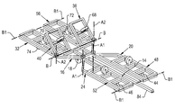
- FIG. 1 is a perspective view of an agricultural implement embodying the present invention in a field position
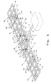
- FIG. 2 is a perspective view of the implement in a first stage of transformation from the field position of FIG. 1 ;
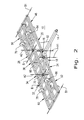
- FIG. 3 is a second stage of transformation of the agricultural implement from the field position of FIG. 1 ;
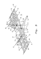
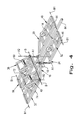
- FIG. 4 is the final transformation of the agricultural implement of FIG. 1 to a transport position.
- FIG. 1 there is shown a large field cultivator 10 .
- the field cultivator 10 is used to prepare the soil in a field for planting of various crops.
- the frame of the cultivator 10 is discussed primarily and certain details of structural bracing are omitted to more clearly focus on the present invention. It should be understood to those skilled on the art that appropriate structural configurations will be incorporated to provide proper strength and rigidity.
- the agricultural implement 10 is typically towed by a tractor 12 , shown schematically.
- a telescoping hitch 14 extends in a forward direction for connection with the tractor 12 .
- the telescoping hitch 14 extends forward from a main frame 16 having main frame lift wheel assemblies 18 providing the support for the implement 10 .
- the main frame 16 and associated frames are illustrated as simple ladder type frames having frame members describing the periphery with intermediate cross frames.
- the cross frames serve to support the wheel assemblies and any ground engaging components provided for the implement 10 .
- the ladder frame is for illustration purposes only and that the frames may take on any one of a variety of configurations to meet load and equipment requirements.
- a left forward inner wing frame 20 is secured to mainframe 16 at a pivotal mounting 22 for pivotal mounting between the illustrated field position in FIG. 1 and a fully configured transport position in FIG. 4 about an axis A 1 that is substantially perpendicular to a plane encompassing main frame 18 and left forward inner wing frame 20 .
- a right forward inner wing frame 24 is secured to the right of main frame 18 at a pivotal mounting 26 , also pivoting about the axis A 1 between the field position of FIG. 1 and the transport position of FIG. 4 .
- a left rear inner wing frame 28 is secured to the aft portion of main frame 16 at a pivotal mounting 30 for pivotal movement between the field position of FIG. 1 and the transport position of FIG. 2 about an axis A 2 which is also substantially perpendicular to the plane of the frames in FIG. 1 .
- a right rear inner wing frame 32 is secured to the rear end of main frame 16 at a pivotal mounting 34 which allows pivoting movement also about axis A 2 .
- the main frame 16 is shown as an isosceles trapezoid with the pivotal mountings 22 and 26 at the ends of the shorter base and the pivotal mountings 30 and 34 at the ends of the longer base.
- the inner edges of the left and right inner wing frames 20 and 24 are configured to mate with the main frame 16 in the field position. It should be apparent to those skilled in the art that other forms may be employed to achieve the same interconnection.
- a left main frame flip up wing frame 36 is secured to left rear inner wing frame 28 at a pivotal mounting 38 for relative pivoting movement about an axis B which extends substantially in a forward and rear direction adjacent the plane of the frame members established in the field position of FIG. 1 .
- a right main frame flip up wing frame 40 is secured to right rear inner wing frame 32 at a pivotal mounting 42 also about an Axis B which extends substantially in a forward and rear direction adjacent the plane of the frames in the field position.
- a left forward inner wing wheel assembly 44 is appropriately structurally connected to left forward inner wing frame 20 for supporting it during the field position and during the transport position of FIG. 4 .
- the left forward inner wheel assembly is established to be a fixed wheel assembly during the field position of FIG. 1 and is a castoring wheel assembly during the transport position of FIG. 4 .
- a right forward inner wing wheel assembly 46 is appropriately structurally connected to the right forward inner wing frame 24 and is a fixed wheel assembly during the field position and a castoring wheel assembly during the transport position of FIG. 4 .
- Additional lateral width may be provided to the agricultural implement 10 by a left forward outer wing frame 48 secured to left forward inner wing frame 20 at a pivotal mounting 50 .
- the left forward outer wing frame is articulated so that it can pivot from the field position of FIG. 1 in which it is substantially in the same plane as the other frame members to flip over onto the left forward inner wing frame 20 .
- a right forward outer wing frame 52 is connected to right forward inner wing frame 24 at a pivotal mounting 54 .
- Both left and right outer forward wing frame members frames 48 and 52 pivot about an axis B 1 which also extends substantially in a forward and rear direction and is adjacent the same plane as the frames in the field position of FIG. 1 .
- the right forward outer wing frame 52 is also pivotable to fold over on top of right forward inner wing frame 24 .
- a left rear outer wing frame 56 is secured to left rear inner wing frame 28 at a pivotal mounting 58 .
- a right rear outer wing frame 60 is connected to right rear inner wing frame 32 at a pivotal mounting 62 .
- the left and right rear outer wing frames 56 and 60 are also pivotable to fold over on their respective inner wing frames substantially about the axis B 1 .
- a left main frame flip up wing frame wheel assembly 68 is appropriately connected to left main frame flip up wing frame 36 for establishing its height in supporting it for ground movement.
- a right main frame flip up wing frame wheel assembly is appropriately connected to flip up frame 40 for the same purpose.
- the wheel assembly 68 and 70 are configured to be fixed wheel assemblies that support and establish the height of the respective flip up frames.
- a left rear inner wing frame wheel assembly 72 is connected to left inner wing frame 28 .
- a right rear inner wing frame wheel assembly 74 is connected to the right rear inner wing frame 32 .
- Wheel assemblies 72 and 74 are configured to be fixed wheel assemblies in the field position shown in FIG. 1 and castoring wheel assemblies in the transport position of FIG. 4 .
- a left rear outer wing frame wheel assembly 76 is appropriately connected to left rear outer wing frame 56 .
- a right rear outer wing frame wheel assembly 78 is secured to right rear outer wing frame 60 .
- Wheel assemblies 76 and 78 are configured to be fixed wheel assemblies directing the outer wing frames in a forward direction and also supporting and setting their heights.
- All of the wheel assemblies are configured to establish and control the height of the frames above the soil in the field position of FIG. 1 .
- the agricultural implement 10 is set up to support a plurality of ground engaging components 80 of a wide variety of types in addition to the illustrated ground engaging component. It should be apparent to those skilled in the art that many ground engaging components may be employed on the agricultural implement 10 as needed for a particular type of farming operation.
- the articulated frames discussed above are described as being positioned between the field position of FIG. 1 and the transport position of FIG. 4 with intermediate configurations. These are achievable by pivoting around their respective axes described above.
- actuator mechanisms would be employed to move the frames between the field position and transport position.
- An example of just one actuator linkage is shown schematically as 82 to pivot right and left forward inner wing frames 20 and 24 about axis A 1 .
- the schematic representation of actuators for the remaining frames have been omitted to provide greater clarity in the articulation of the frame members. It should be apparent to those skilled in the art that suitable actuators may be employed to manipulate the frames between their field position of FIG. 1 and transport position of FIG. 4 .
- the discussion of the folding operation will proceed from the configuration shown in FIG. 1 in which the agricultural implement is deployed in a field.
- the frames are substantially in a single plane extending to a maximum lateral width and towed in a forward direction by tractor 12 .
- All of the wheel assemblies are configured to have a fixed direction, but are adjustable to set the overall distance of the plane of the frames relative to the ground.
- the agricultural implement 10 is first moved to the configuration shown in FIG. 2 in which the right and left forward and rear outer wing frames are folded over on top of their inner wing frames.
- the right and left main frame flip up frames 36 and 40 are pivoted to their illustrated position which forms approximately a 135° angle relative to their field position of FIG. 1 as shown in FIG. 3 .
- the purpose of flipping up the frames 36 and 40 is to clear the previously occupied space to the rear of main frame 16 and that a range of angles is permitted according to the clearance limitations of wheel assemblies and ground engaging components 80 .
- the left and right rear inner wing frames 28 and 32 are pivoted about their respective pivotal mountings 30 and 34 swing about the axis A 2 to the position of FIG. 4 where the inner section of the frames 28 and 32 now occupies the space previously occupied by the flip frames 36 and 40 .
- the left and right inner wing frames 20 and 24 are pivoted to the forward position wherein they extend alongside hitch 44 .
- a telescoping attachment 84 is provided to hitch 14 .
- the wheel assemblies 44 , 46 , 72 and 74 are configured to be castoring wheels in the transport position of FIG. 4 so as to permit a movement that is substantially at a right angle to the field movement.
Landscapes
- Life Sciences & Earth Sciences (AREA)
- Engineering & Computer Science (AREA)
- Mechanical Engineering (AREA)
- Soil Sciences (AREA)
- Environmental Sciences (AREA)
- Agricultural Machines (AREA)
Abstract
Description
- The present invention relates to agricultural implement, and, more specifically to folding frames for such implements.
- In the quest for greater efficiency in agricultural operations, a demand has been placed on field cultivating implements to achieve a lateral width that is ever increasing. Increased lateral widths of up to over 80 feet wide for a single machine allow a farmer to cultivate a wider swath of field for a given pass of the implement. However, the field cultivator must be transported between fields and during the transport operation it must fit within the height and width regulations of governments for over the highway clearance requirements. In an attempt to do this, frame members for the agricultural implements have been articulated to one another so that they may extend laterally a maximum width and then are folded on top of one another and forward to minimize the cross section of the implement in a transport position. The need to achieve ever greater width strains the ability of the current arrangements to fit within the highway requirements for a transport position.
- Accordingly, what is needed in the art is a folding frame member having a minimum cross section for the transport position.
- The present invention seeks to achieve that in a configuration that is easily achieved.
- In one form, the invention is a folding frame for an agricultural implement having ground support wheels secured thereto and ground engaging components supported by a frame. The frame includes a main frame member and at least one inner wing frame member articulated to the main frame member between a field position in which it extends laterally and in substantially the same plane as the main frame member and a transport position wherein it is pivoted about an axis that is substantially perpendicular to the plane of the main frame member. A main frame flip frame member is articulated to the inner wing frame member between a field position in which it is in substantially the same plane as the inner wing frame member and the main frame and a transport position in which it is pivoted out of the plane of the inner frame member so that when the inner wing frame member is pivoted it occupies the space previously occupied by the main frame flip frame member.
- The invention, in another form, is directed to a method for folding a frame for an agricultural implement having a main frame and at least one inner wing frame member articulated to the main frame for extended field position and a transport position and a flip frame member articulated to the inner wing frame member. The method includes the steps of pivoting the flip frame member out of the plane of the inner wing member and pivoting the inner wing frame member to extend aft from the main frame into the space previously occupied by the flip frame member.
- An advantage of the present invention is that agricultural implements of ever increasing lateral span may be transported between fields within existing governmental clearance limitations.
- Another advantage is that the agricultural implements may also have minimal reduced height clearance requirements during the transport position.
- The above-mentioned and other features and advantages of this invention, and the manner of attaining them, will become more apparent and the invention will be better understood by reference to the following description of an embodiment of the invention taken in conjunction with the accompanying drawings, wherein:
-
FIG. 1 is a perspective view of an agricultural implement embodying the present invention in a field position; -
FIG. 2 is a perspective view of the implement in a first stage of transformation from the field position ofFIG. 1 ; -
FIG. 3 is a second stage of transformation of the agricultural implement from the field position ofFIG. 1 ; and -
FIG. 4 is the final transformation of the agricultural implement ofFIG. 1 to a transport position. - Corresponding reference characters indicate corresponding parts throughout the several views. The exemplification set out herein illustrates one embodiment of the invention and such exemplification is not to be construed as limiting the scope of the invention in any manner.
- Referring now to the drawings, and more particularly to
FIG. 1 , there is shown alarge field cultivator 10. Thefield cultivator 10 is used to prepare the soil in a field for planting of various crops. The frame of thecultivator 10 is discussed primarily and certain details of structural bracing are omitted to more clearly focus on the present invention. It should be understood to those skilled on the art that appropriate structural configurations will be incorporated to provide proper strength and rigidity. Theagricultural implement 10 is typically towed by atractor 12, shown schematically. Atelescoping hitch 14 extends in a forward direction for connection with thetractor 12. Thetelescoping hitch 14 extends forward from amain frame 16 having main framelift wheel assemblies 18 providing the support for theimplement 10. Themain frame 16 and associated frames are illustrated as simple ladder type frames having frame members describing the periphery with intermediate cross frames. In this instance, the cross frames serve to support the wheel assemblies and any ground engaging components provided for theimplement 10. It should be pointed out that the ladder frame is for illustration purposes only and that the frames may take on any one of a variety of configurations to meet load and equipment requirements. - The subsequent discussion of additional frames is described from a view behind the
implement 10 looking forward in the direction of thetractor 12. A left forwardinner wing frame 20 is secured tomainframe 16 at a pivotal mounting 22 for pivotal mounting between the illustrated field position inFIG. 1 and a fully configured transport position inFIG. 4 about an axis A1 that is substantially perpendicular to a plane encompassingmain frame 18 and left forwardinner wing frame 20. A right forwardinner wing frame 24 is secured to the right ofmain frame 18 at a pivotal mounting 26, also pivoting about the axis A1 between the field position ofFIG. 1 and the transport position ofFIG. 4 . A left rearinner wing frame 28 is secured to the aft portion ofmain frame 16 at apivotal mounting 30 for pivotal movement between the field position ofFIG. 1 and the transport position ofFIG. 2 about an axis A2 which is also substantially perpendicular to the plane of the frames inFIG. 1 . A right rearinner wing frame 32 is secured to the rear end ofmain frame 16 at apivotal mounting 34 which allows pivoting movement also about axis A2. - The
main frame 16 is shown as an isosceles trapezoid with the pivotal mountings 22 and 26 at the ends of the shorter base and thepivotal mountings inner wing frames main frame 16 in the field position. It should be apparent to those skilled in the art that other forms may be employed to achieve the same interconnection. - A left main frame flip up
wing frame 36 is secured to left rearinner wing frame 28 at apivotal mounting 38 for relative pivoting movement about an axis B which extends substantially in a forward and rear direction adjacent the plane of the frame members established in the field position ofFIG. 1 . A right main frame flip upwing frame 40 is secured to right rearinner wing frame 32 at apivotal mounting 42 also about an Axis B which extends substantially in a forward and rear direction adjacent the plane of the frames in the field position. - A left forward inner
wing wheel assembly 44 is appropriately structurally connected to left forwardinner wing frame 20 for supporting it during the field position and during the transport position ofFIG. 4 . The left forward inner wheel assembly is established to be a fixed wheel assembly during the field position ofFIG. 1 and is a castoring wheel assembly during the transport position ofFIG. 4 . A right forward innerwing wheel assembly 46 is appropriately structurally connected to the right forwardinner wing frame 24 and is a fixed wheel assembly during the field position and a castoring wheel assembly during the transport position ofFIG. 4 . - Additional lateral width may be provided to the
agricultural implement 10 by a left forwardouter wing frame 48 secured to left forwardinner wing frame 20 at apivotal mounting 50. The left forward outer wing frame is articulated so that it can pivot from the field position ofFIG. 1 in which it is substantially in the same plane as the other frame members to flip over onto the left forwardinner wing frame 20. A right forwardouter wing frame 52 is connected to right forwardinner wing frame 24 at a pivotal mounting 54. Both left and right outer forward wing frame members frames 48 and 52 pivot about an axis B1 which also extends substantially in a forward and rear direction and is adjacent the same plane as the frames in the field position ofFIG. 1 . The right forwardouter wing frame 52 is also pivotable to fold over on top of right forwardinner wing frame 24. A left rearouter wing frame 56 is secured to left rearinner wing frame 28 at apivotal mounting 58. A right rearouter wing frame 60 is connected to right rearinner wing frame 32 at apivotal mounting 62. The left and right rearouter wing frames - A left main frame flip up wing
frame wheel assembly 68 is appropriately connected to left main frame flip upwing frame 36 for establishing its height in supporting it for ground movement. A right main frame flip up wing frame wheel assembly is appropriately connected to flip upframe 40 for the same purpose. Thewheel assembly - A left rear inner wing
frame wheel assembly 72 is connected to leftinner wing frame 28. A right rear inner wingframe wheel assembly 74 is connected to the right rearinner wing frame 32.Wheel assemblies FIG. 1 and castoring wheel assemblies in the transport position ofFIG. 4 . - A left rear outer wing
frame wheel assembly 76 is appropriately connected to left rearouter wing frame 56. A right rear outer wingframe wheel assembly 78 is secured to right rearouter wing frame 60.Wheel assemblies - All of the wheel assemblies are configured to establish and control the height of the frames above the soil in the field position of
FIG. 1 . - The agricultural implement 10 is set up to support a plurality of
ground engaging components 80 of a wide variety of types in addition to the illustrated ground engaging component. It should be apparent to those skilled in the art that many ground engaging components may be employed on the agricultural implement 10 as needed for a particular type of farming operation. - The articulated frames discussed above are described as being positioned between the field position of
FIG. 1 and the transport position ofFIG. 4 with intermediate configurations. These are achievable by pivoting around their respective axes described above. As would be typical for the art, actuator mechanisms would be employed to move the frames between the field position and transport position. An example of just one actuator linkage is shown schematically as 82 to pivot right and left forward inner wing frames 20 and 24 about axis A1. The schematic representation of actuators for the remaining frames have been omitted to provide greater clarity in the articulation of the frame members. It should be apparent to those skilled in the art that suitable actuators may be employed to manipulate the frames between their field position ofFIG. 1 and transport position ofFIG. 4 . - The discussion of the folding operation will proceed from the configuration shown in
FIG. 1 in which the agricultural implement is deployed in a field. In this position, the frames are substantially in a single plane extending to a maximum lateral width and towed in a forward direction bytractor 12. All of the wheel assemblies are configured to have a fixed direction, but are adjustable to set the overall distance of the plane of the frames relative to the ground. When field operations are completed, the agricultural implement 10 is first moved to the configuration shown inFIG. 2 in which the right and left forward and rear outer wing frames are folded over on top of their inner wing frames. - When this is completed, the right and left main frame flip up frames 36 and 40 are pivoted to their illustrated position which forms approximately a 135° angle relative to their field position of
FIG. 1 as shown inFIG. 3 . It should be apparent, though that the purpose of flipping up theframes main frame 16 and that a range of angles is permitted according to the clearance limitations of wheel assemblies andground engaging components 80. Once the flip up frames 36 and 40 are out of the way, the left and right rear inner wing frames 28 and 32 are pivoted about their respectivepivotal mountings FIG. 4 where the inner section of theframes hitch 44. In order to accommodate the additional forward length of theframes telescoping attachment 84 is provided to hitch 14. As stated above, thewheel assemblies FIG. 4 so as to permit a movement that is substantially at a right angle to the field movement. - The configuration set out above allows agricultural implements of substantial lateral field position to be folded into a transport configuration that is significantly reduced to easily fall within the limits set forth by various governmental regulations. This enables an even greater lateral limit to be achieved in the field position while still maintaining a transport position in which the frames are adequately and appropriately supported for transport between fields. By having the pivotal axis A2 position at the forward edge of the rear inner wing frames, they are swung inward to minimize the transport width.
- While this invention has been described with respect to at least one embodiment, the present invention can be further modified within the spirit and scope of this disclosure. This application is therefore intended to cover any variations, uses, or adaptations of the invention using its general principles. Further, this application is intended to cover such departures from the present disclosure as come within known or customary practice in the art to which this invention pertains and which fall within the limits of the appended claims.
Claims (13)
Priority Applications (1)
| Application Number | Priority Date | Filing Date | Title |
|---|---|---|---|
| US15/289,515 US9968026B2 (en) | 2016-10-10 | 2016-10-10 | Apparatus and method for an agricultural implement folding frame |
Applications Claiming Priority (1)
| Application Number | Priority Date | Filing Date | Title |
|---|---|---|---|
| US15/289,515 US9968026B2 (en) | 2016-10-10 | 2016-10-10 | Apparatus and method for an agricultural implement folding frame |
Publications (2)
| Publication Number | Publication Date |
|---|---|
| US20180098482A1 true US20180098482A1 (en) | 2018-04-12 |
| US9968026B2 US9968026B2 (en) | 2018-05-15 |
Family
ID=61829436
Family Applications (1)
| Application Number | Title | Priority Date | Filing Date |
|---|---|---|---|
| US15/289,515 Active US9968026B2 (en) | 2016-10-10 | 2016-10-10 | Apparatus and method for an agricultural implement folding frame |
Country Status (1)
| Country | Link |
|---|---|
| US (1) | US9968026B2 (en) |
Family Cites Families (30)
| Publication number | Priority date | Publication date | Assignee | Title |
|---|---|---|---|---|
| US2787477A (en) * | 1954-10-19 | 1957-04-02 | Edward G Melroe | Folding drawbar and transport |
| US3539016A (en) * | 1967-09-28 | 1970-11-10 | Clark Equipment Co | Actuating means for foldable implement carriage |
| US3548954A (en) * | 1967-09-28 | 1970-12-22 | Clark Equipment Co | Foldable carriage for earth working implement |
| US3866688A (en) | 1972-12-13 | 1975-02-18 | Koehring Co | Field cultivator wing lift |
| US3967684A (en) | 1974-08-01 | 1976-07-06 | Deere & Company | Wingfold positioning device |
| US4271711A (en) | 1979-02-28 | 1981-06-09 | Green Line, Inc. | 180 Degree folding device |
| US4355690A (en) | 1980-12-18 | 1982-10-26 | Deere & Company | Stack folding outrigger system |
| US4336846A (en) | 1981-03-05 | 1982-06-29 | International Harvester Co. | Agricultural folding tool bar |
| US4529040A (en) * | 1981-08-27 | 1985-07-16 | Grollimund David J | Folding agricultural implement with structure for locking tool bar sections |
| US4418763A (en) | 1981-10-01 | 1983-12-06 | International Harvester Co. | Agricultural folding tool bar |
| US4415043A (en) | 1981-10-01 | 1983-11-15 | Chromalloy American Corporation | Toolbar with wings foldable substantially 180 degrees |
| US4576238A (en) * | 1983-08-22 | 1986-03-18 | Marliss Industries, Inc. | Folding outrigger attachment for farm implements |
| US5839516A (en) | 1996-03-12 | 1998-11-24 | Unverferth Manufacturing Co., Inc. | Folding frame assembly for a rolling harrow implement having a transport position in which the main frame is upwardly pivoted and the wing frames are forwardly pivoted |
| GB9613873D0 (en) * | 1996-07-02 | 1996-09-04 | Flexi Coil Ltd | Bi-fold implement frame and slim cultivator |
| US5921325A (en) | 1997-06-18 | 1999-07-13 | Great Plains Manufacturing, Incorporated | Low transport height stack fold implement |
| US6092609A (en) | 1998-09-09 | 2000-07-25 | Jeffery; Herbert | Flexible folding agricultural implement |
| US6293352B1 (en) * | 1998-11-12 | 2001-09-25 | Flexi-Coil Ltd. | Telescoping hitch for planting implement |
| US7740084B2 (en) * | 2000-05-02 | 2010-06-22 | Lyn Rosenboom | Agricultural implement frame, track assembly and cart |
| US6220366B1 (en) | 2000-08-09 | 2001-04-24 | Deere & Company | Wheel control structure for a folding implement |
| US7562719B1 (en) * | 2006-03-10 | 2009-07-21 | Misenhelder John G | Tool bar with forward folding wings |
| US7581597B2 (en) | 2006-04-14 | 2009-09-01 | Cnh Canada, Ltd. | System for and method of moving an agricultural implement between a folded, inoperative position and an extended, operative position |
| US7469648B2 (en) | 2006-08-31 | 2008-12-30 | Cnh America, Llc | Front fold planter lift and fold hydraulic control system |
| US7854272B2 (en) | 2008-10-24 | 2010-12-21 | Cnh Canada, Ltd. | Agricultural implement having forward folding wing booms |
| US8567517B2 (en) * | 2010-05-20 | 2013-10-29 | Cnh Canada, Ltd. | Agricultural implement tool frame actuating system |
| US8176992B2 (en) * | 2010-05-28 | 2012-05-15 | Cnh Canada, Ltd. | Electronically controlled hydraulic system for an agricultural implement |
| US8636078B2 (en) * | 2010-05-28 | 2014-01-28 | Cnh Canada, Ltd. | Mechanically controlled hydraulic system for an agricultural implement |
| US8342256B2 (en) * | 2010-06-29 | 2013-01-01 | Cnh America Llc | Foldable farm implement |
| US8770309B2 (en) | 2010-11-29 | 2014-07-08 | Environmental Tillage Systems, Inc. | Wide swath folding tool bar assembly |
| US8820429B2 (en) * | 2011-03-30 | 2014-09-02 | Cnh Industrial America Llc | Fertilizer applicator with in-frame folding actuator for folding an outer frame member relative to an inner frame member |
| US9549496B2 (en) * | 2013-12-11 | 2017-01-24 | Cnh Industrial America Llc | Tillage implement with foldable frame |
-
2016
- 2016-10-10 US US15/289,515 patent/US9968026B2/en active Active
Also Published As
| Publication number | Publication date |
|---|---|
| US9968026B2 (en) | 2018-05-15 |
Similar Documents
| Publication | Publication Date | Title |
|---|---|---|
| US8127861B2 (en) | Front folding agricultural implement frame with rearwardly telescoping tongue | |
| US11751498B2 (en) | Toolbar system for an agricultural implement | |
| US8528657B1 (en) | Folding agricultural tool carrier having compact storage position | |
| US8770309B2 (en) | Wide swath folding tool bar assembly | |
| US10912248B2 (en) | Mowing device | |
| US20110315410A1 (en) | Planter with four bar linkage | |
| EP2589283B1 (en) | Combined soil cultivation device for large work widths with collapsible side sections | |
| US10172276B2 (en) | Implement frame convertible between field and transport positions | |
| US6257343B1 (en) | Compact folding row marker | |
| US5794712A (en) | Mobile frame | |
| CA2883187A1 (en) | Land roller implement having multi-roller wings with fold-over subframes | |
| US9955621B2 (en) | Front fold implement frame with pivotal draft link connection | |
| EP1529430A1 (en) | Device at a soil tillage implement | |
| US9968026B2 (en) | Apparatus and method for an agricultural implement folding frame | |
| US4502545A (en) | Folding tool beam and lift assembly | |
| CA3186142C (en) | FLEXIBLE AGRICULTURAL ACCESSORY | |
| DE19916759A1 (en) | Rotary swather for cutting swathes, in harvesting; has rake wheel fixed to supports hinged to machine frame, where machine frame or undercarriage connected to machine frame is telescopic | |
| US4031965A (en) | Tillage tool wing folding kit | |
| US9585300B2 (en) | Folding agricultural implement hinge system | |
| AU2016200288B2 (en) | Land roller implement having multi-roller wings with fold-over subframes | |
| EA049442B1 (en) | AGRICULTURAL DEVICE FOR SOIL CULTIVATION AND METHOD OF FOLDING AN AGRICULTURAL DEVICE | |
| GB2198323A (en) | Ground or crop treatment implements | |
| ZA201101065B (en) | Support frame | |
| DD147033A1 (en) | Lifting and swiveling device for floor work tools |
Legal Events
| Date | Code | Title | Description |
|---|---|---|---|
| AS | Assignment |
Owner name: CNH INDUSTRIAL AMERICA LLC, PENNSYLVANIA Free format text: ASSIGNMENT OF ASSIGNORS INTEREST;ASSIGNOR:SUDBRINK, MATTHEW R.;REEL/FRAME:040297/0949 Effective date: 20161006 |
|
| STCF | Information on status: patent grant |
Free format text: PATENTED CASE |
|
| AS | Assignment |
Owner name: BLUE LEAF I.P., INC., DELAWARE Free format text: ASSIGNMENT OF ASSIGNORS INTEREST;ASSIGNOR:CNH INDUSTRIAL AMERICA LLC;REEL/FRAME:047494/0078 Effective date: 20181011 |
|
| MAFP | Maintenance fee payment |
Free format text: PAYMENT OF MAINTENANCE FEE, 4TH YEAR, LARGE ENTITY (ORIGINAL EVENT CODE: M1551); ENTITY STATUS OF PATENT OWNER: LARGE ENTITY Year of fee payment: 4 |
|
| FEPP | Fee payment procedure |
Free format text: MAINTENANCE FEE REMINDER MAILED (ORIGINAL EVENT CODE: REM.); ENTITY STATUS OF PATENT OWNER: LARGE ENTITY |