US20180098479A1 - Wear resistant disk blade and agricultural machine with wear resistant disk blade - Google Patents
Wear resistant disk blade and agricultural machine with wear resistant disk blade Download PDFInfo
- Publication number
- US20180098479A1 US20180098479A1 US15/615,404 US201715615404A US2018098479A1 US 20180098479 A1 US20180098479 A1 US 20180098479A1 US 201715615404 A US201715615404 A US 201715615404A US 2018098479 A1 US2018098479 A1 US 2018098479A1
- Authority
- US
- United States
- Prior art keywords
- blade
- disk
- outer edge
- bead
- blade body
- Prior art date
- Legal status (The legal status is an assumption and is not a legal conclusion. Google has not performed a legal analysis and makes no representation as to the accuracy of the status listed.)
- Granted
Links
Images


Classifications
-
- A—HUMAN NECESSITIES
- A01—AGRICULTURE; FORESTRY; ANIMAL HUSBANDRY; HUNTING; TRAPPING; FISHING
- A01B—SOIL WORKING IN AGRICULTURE OR FORESTRY; PARTS, DETAILS, OR ACCESSORIES OF AGRICULTURAL MACHINES OR IMPLEMENTS, IN GENERAL
- A01B23/00—Elements, tools, or details of harrows
- A01B23/06—Discs; Scrapers for cleaning discs; Sharpening attachments
-
- A—HUMAN NECESSITIES
- A01—AGRICULTURE; FORESTRY; ANIMAL HUSBANDRY; HUNTING; TRAPPING; FISHING
- A01B—SOIL WORKING IN AGRICULTURE OR FORESTRY; PARTS, DETAILS, OR ACCESSORIES OF AGRICULTURAL MACHINES OR IMPLEMENTS, IN GENERAL
- A01B33/00—Tilling implements with rotary driven tools, e.g. in combination with fertiliser distributors or seeders, with grubbing chains, with sloping axles, with driven discs
- A01B33/02—Tilling implements with rotary driven tools, e.g. in combination with fertiliser distributors or seeders, with grubbing chains, with sloping axles, with driven discs with tools on horizontal shaft transverse to direction of travel
- A01B33/021—Tilling implements with rotary driven tools, e.g. in combination with fertiliser distributors or seeders, with grubbing chains, with sloping axles, with driven discs with tools on horizontal shaft transverse to direction of travel with rigid tools
- A01B33/024—Tilling implements with rotary driven tools, e.g. in combination with fertiliser distributors or seeders, with grubbing chains, with sloping axles, with driven discs with tools on horizontal shaft transverse to direction of travel with rigid tools with disk-like tools
-
- B22F1/02—
-
- B—PERFORMING OPERATIONS; TRANSPORTING
- B22—CASTING; POWDER METALLURGY
- B22F—WORKING METALLIC POWDER; MANUFACTURE OF ARTICLES FROM METALLIC POWDER; MAKING METALLIC POWDER; APPARATUS OR DEVICES SPECIALLY ADAPTED FOR METALLIC POWDER
- B22F1/00—Metallic powder; Treatment of metallic powder, e.g. to facilitate working or to improve properties
- B22F1/16—Metallic particles coated with a non-metal
-
- B—PERFORMING OPERATIONS; TRANSPORTING
- B23—MACHINE TOOLS; METAL-WORKING NOT OTHERWISE PROVIDED FOR
- B23K—SOLDERING OR UNSOLDERING; WELDING; CLADDING OR PLATING BY SOLDERING OR WELDING; CUTTING BY APPLYING HEAT LOCALLY, e.g. FLAME CUTTING; WORKING BY LASER BEAM
- B23K26/00—Working by laser beam, e.g. welding, cutting or boring
- B23K26/34—Laser welding for purposes other than joining
Definitions
- This disclosure pertains to agricultural machines such as seeding or planting machines or tillage machines and in particular to wear resistant disk blades for such machines.
- Disk blades are used in agricultural machines in a variety of ways, including tillage of soil as well as to open a furrow in the soil to apply seed, fertilizer or other commodities. Due to the harsh conditions in which the blades-operate, they are subject to wear and require regular replacement. A need exists for increasing the service life of the disk blades.
- the disclosure provides an agricultural machine that includes a frame and at least one disk blade carried by the frame.
- the disk blade has a circular blade body of a first base material having a first hardness.
- the blade body has top and bottom surfaces and an outer edge extending around the blade body.
- At least one bead of cladding extends circumferentially around the blade body on the bottom surface adjacent the outer edge. This cladding is of a second hardness greater than the first hardness of the base material.
- the disclosure provides a disk blade for an agricultural machine having a circular blade body of a first base material with a first hardness.
- the blade body has top and bottom surfaces and an outer edge extending around the blade body.
- At least one bead of cladding extends circumferentially around the blade body on the bottom surface adjacent the outer edge. This cladding is of a second hardness greater than the first hardness of the base material.
- the disclosure provides a disk blade for an agricultural machine having a circular blade body of a first base material having a first hardness.
- the blade body has top and a bottom surfaces and an outer edge extending around the blade body.
- a plurality of clad beads extend radially inwardly from the outer edge, having a second harness greater than the first hardness
- the beads are curved so as to be more tangential to the outer edge at outer ends of the beads and curved radially inwardly to a more radial direction at inner ends of the beads.
- the disclosure provides a disk blade for an agricultural machine having a circular blade body of a first base material having a first hardness.
- the blade body has top and a bottom surfaces and an outer edge extending around the blade body. A portion of the bottom surface of the blade body is recessed.
- the recess is filled with a clad bead having a second hardness that is greater than the first hardness.
- the clad bead has a surface that is generally flush with the bottom surface of the blade body.
- FIG. 1 is a plan view of a seeding tool for depositing seed and fertilizer into furrows in the soil as the machine is moved across a soil surface;
- FIG. 2 is a perspective view of a single disk opener assembly of the tool shown in FIG. 1 ;
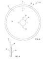
- FIG. 3 is a plan view of a top surface of an opener disk blade of the opener assembly of FIG. 2 ;
- FIG. 4 is a sectional view of the disk blade of FIG. 3 as seen from the line 4 - 4 of FIG. 3 ;
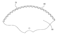
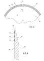
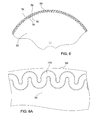
- FIG. 5 is a fragmentary plan view of a bottom surface of the disk blade illustrating one embodiment of the hardened material beads on the disk blade;
- FIG. 6 is a sectional view of the disk blade of FIG. 5 as seen from the line 6 - 6 of FIG. 5 illustrating the beads of hardened material;
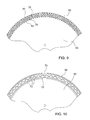
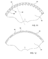
- FIGS. 7-12 are fragmentary plan views of a bottom surface of the disk blade illustrating additional embodiments of the hardened material beads on the disk blade.
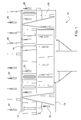
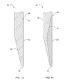
- FIGS. 13 and 14 are sectional views of alternative constructions where the clad hardened material is inlaid in a recess in the blade base material:
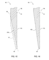
- FIG. 15 is a sectional view similar to FIG. 13 illustrating a wear pattern of the disk blade
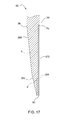
- FIG. 16 is a sectional view of yet another embodiment where the bevel extends radially inward approximately the same extent as the clad bead;
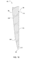
- FIG. 17 is a sectional view of another alternative where the bevel has two bevel portions having different bevel angles.
- Tool 10 includes a frame 16 supported on wheels 14 and equipped with a tongue 12 for coupling to a towing vehicle, such as an agricultural tractor, not shown.
- the tool 10 is has a plurality of opener assemblies 20 for opening a furrow in the soil to deposit seeds therein. Seed or commodity stored in tank 18 is delivered to the openers from a metering assembly (not shown) by a pneumatic distribution system (not shown) in a well-known manner.
- Single disk opener assembly 20 is shown in greater detail in FIG. 2 .
- the opener assembly 20 is exemplary of a variety of different arrangements of single disk openers.
- Opener assembly 20 may be used for seed, fertilizer or for other chemicals.
- Opener assembly 20 has a frame 22 which includes a linkage 24 which is biased downward by a compression coil spring 26 .
- a disk blade 30 is mounted to the linkage 24 for rotation as the machine moves through a field. The disk blade is slightly angled relative to the forward travel direction shown by the arrow 32 to form a shallow furrow in the soil.
- a quick depth adjuster 34 moves a gauge wheel 36 (on the back side of the disk 30 ) relative to the disk blade 30 to set the depth of penetration of the disk blade 30 into the soil and thus the depth of the furrow formed in the soil.
- the gauge wheel 36 is on the side of the disk blade body and may contact the blade body surface or be closely to the blade body surface to clear dirt and mud off the disk blade.
- a seed boot 38 includes a tube 40 for directing seed or fertilizer into the furrow.
- a closing wheel 42 is positioned behind and to the side of the boot 38 to close the furrow after seed or fertilizer has been deposited therein.
- the opener disk blade 30 operates in soil which may be abrasive and may also contain rocks and other objects that damage (dull, wear out, ding, chip, bend) the blade edge.
- the disk blade is a component that is frequently replaced during the life of the tool 10 .
- Blade replacement is not inexpensive as larger tools may have 75 to 100, or more disk blades.
- considerable time is required to remove and replace the blades.
- the challenges result from adding heat to the perimeter of the disk, causing it to warp, weak bonds between the coating and the base disk material, which result in chipping of the coating followed by uneven wear which effects seed placement, and the effects of the added thickness of the coating on the disks' ability to retain a thin profile which is required to penetrate into hard soils and to cut through crop residue.
- the disk blade 30 has a generally circular blade body 50 made of a first base material having a first hardness.
- the base material may be a heat treated carbon-boron steel such as Deere Part number N283804, though other steel alloys may be used. All, or only the outer portion, of the disk blade body may be heat treated.
- the body 50 has a central aperture 52 and bolt holes 54 for mounting the blade to a bearing hub on the linkage 24 .
- the blade body has a top surface 56 and bottom surface 58 . In the example blade body 50 shown in FIG. 3 , the blade thickness is approximately 5 mm, although the blade body can have other thicknesses. Near the outer edge 60 , the top surface 56 is formed with a bevel 62 , FIG.
- the thickness of the outer edge 60 may be about 1 mm.
- the outer edge 60 functions as a cutting edge as the blade moves through the soil. The cutting edge cuts into the soil and is intended to cut through any plant residue remaining on or within the soil. If the cutting edge wears and becomes dulled, the blade may not cut through plant residue, but instead pushes the residue into the furrow, called “hairpinning,” producing a less than optimum environment for seed germination and plant growth. For proper functioning, it is necessary to maintain the cutting edge.
- the disk blade is mounted to the opener assembly 20 at a slight angel to the forward direction so as to form a generally V-shaped furrow in the soil.
- the top surface 56 with the bevel 62 is on the rearward facing side while the flat bottom surface 58 confronts the soil in the forward direction. As such, it is the bottom surface 58 that is subject to the most wear. Thus, cladding this surface reduces the wear and extends the disk blade life.
- a bead of hardened material is applied to the bottom surface 58 near the outer edge 60 .
- the hardened material has a second hardness that is greater than the first hardness of the base material of the blade body.
- the bead may be made of metallic alloy containing hard phase precipitates such as a metallic carbide or metallic boride.
- a metallic matrix carbide such as RockitTM 701 from Hoganas AB of Sweden.
- Other metallic matrix carbides or borides may be used as well.
- the hardened material is metallurgically bonded to the base material.
- the bead may be applied by laser cladding, Plasma Transferred Arc (PTA) process, welding or other direct metal deposition methods.
- PTA Plasma Transferred Arc
- the bead may be about 2 mm in width and 0.35-0.5 mm in thickness. Other thicknesses and widths may be used.
- the hardness of the hardened material that is the second hardness, may be between 700-1300 HV (Vickers Hardness).
- the bead is a line of the hardened material which can be a single narrow pass around the blade body near the outer edge, multiple narrow passes, either adjacent and touching one another or spaced from one another, or a single or multiple wide passes.
- one or more beads of hardened material are applied as continuous beads, circumferentially, near the outer edge 60 .
- three beads 70 are concentrically arranged near the outer edge 60 .
- Beads 70 are said to be straight beads as they are each a constant distance from the outer edge 60 , or in other words, parallel to the outer edge 60 .
- the beads may have a width of about 5 mm.
- the concentric beads may be spaced apart from one another or placed so as to touch one another.
- a single bead, or band, of hardened material may be placed on the blade having a width ranging from less than 1.5 mm to greater than 30 mm.
- FIG. 7 An alternative bead arrangement is shown in FIG. 7 where a continuous bead 72 is applied circumferentially near the outer edge 60 .
- bead 72 is a “wavy” bead, similar to the form of a sine wave having smooth repetitive oscillations of varying distance from the outer edge 60 .
- This bead may have a width of 5 mm but could be smaller or larger.
- a band having a width of 1.5 to 30 mm can be applied in a wavy pattern as well.
- a wide bead 172 of cladding is applied in a wavy pattern.
- the wide bead can be anywhere between 1.5 and 30 mm in width or even larger if desired. As with the other “wavy” beads shown, this allows the edge to wear in a serrated manner.
- FIG. 8 Another alternative wavy bead 74 is shown in FIG. 8 having a shorter “wavelength” compared to the bead 72 of FIG. 7 .
- the “legs” 76 of the wave, between the apexes 78 are substantially radially extending relative to the central rotational axis of the disk blade 30 .
- the bead 74 is shown having a thickness or width of approximately 5 mm.
- FIG. 8A a similar wavy bead 174 is shown but having a greater bead width, on the order of 8-10 mm resulting in a greater portion of the disk surface 50 being coated with the cladding material compared to the bead 74 of FIG. 8 .
- wavy beads 80 and 82 can be applied concentrically as shown in FIG. 9 .
- the disk may wear in a serrated pattern between the outer apexes of the bead. This will may facilitate keeping the edge 60 sharp enough to cut through plant residue.
- Both straight beads 70 and wavy beads 72 can applied together as shown in FIG. 10 .
- a wavy bead 72 is place concentrically between two straight beads 70 .
- the apexes of the wavy bead are shown touching the straight beads, however, the beads can be spaced from one another.
- the legs 84 of the wavy bead 82 are arranged at a substantial angle relative to a radial line 86 . This produces a generally “saw-tooth” pattern for the bead 82 .
- a further embodiment does not include a continuous bead about the periphery of the disk blade but rather has a plurality of short, curved beads extending inwardly from the outer edge 60 .
- beads 90 are shown which start near the outer edge and curve radial inwardly toward the center of the disk. At the outer edge, the beads are closer to being tangent to the outer edge, but the beads then curve inwardly, to a more radial direction near the bead inner ends.
- the beads are spaced apart so that as the base material wears between the beads, a serrated edge forms on the disk blade outer edge 60 .
- FIG. 13 An alternative embodiment is shown in FIG. 13 where the clad bead 170 is inlaid within a recess 72 in the bottom surface 58 of the blade body. This results in a substantially continuous bottom surface of the blade body. While the surface of the clad bead will not be as smooth as the surface of the blade body, the clad bead will not be projecting beyond the blade surface, where it could damage the gauge wheel 36 adjacent to or contacting the blade surface.
- FIG. 14 shows yet another alternative where the bead 270 is inlaid into a deeper recess or cut-out 74 in the bottom surface 58 of the blade base. This provides more wear resistant material at the outer edge of the blade. As shown in FIG.
- the cladding 170 is applied to the flat side 58 of the disk as opposed to the beveled side 56 .
- This allows the disk to wear in a manner that maintains a sharp edge.
- the wear rate and sharpness of the disk can be controlled in order to maintain the optimal cutting edge on the disk.
- the surface of the bevel wears radially inward as indicated by the line 62 A. As it does so, the surface continues to maintain the bevel, resulting in a narrow edge that is sharp.
- the cladding is applied to the beveled surface, as the base material wears radially inward on the flat side, an increasingly thicker blunt edge will be produced.
- the cladding reduces the rate of blade wear, thus increasing the disk life.
- the life of the disk can be further increased by maintaining a sharp edge.
- a typical disk may have a diameter of 18 inches and the equipment manufacturer may recommend replacing the disk when it wears to a diameter of 16 inches. However, many farmers replace the disks at 17 or 16.5 inches primarily due to lack of edge sharpness. If the disk edge can be maintained sharp, the disk blade life may be further extended by remaining in service until it reaches a 16 inch diameter.
- the edge sharpness is maintained by cladding the wear resistant material onto the flat surface of the disk, allowing the base material of beveled edge to wear.
- the sharper edge may be maintained to a diameter of 16 inches by increasing the radial extend of the beveled surface 162 as shown in FIG. 16 .
- the beveled edge 162 extends radially inward to approximately the radial inner edge of the cladding 170 .
- the cladding and bevel may extend inwardly between 20 mm and 40 mm from the edge 60 . This may allow the disk to wear to a diameter of about 16 inches or less before the beveled edge and cladding is worn off.
- An alternative extended bevel is shown in FIG. 17 .
- an outer bevel portion 262 has a first bevel angle “a.”
- the bevel angle being the angle of the surface of the bevel 262 relative to a line 264 parallel to the blade body surface 56 .
- a radially inner bevel portion 266 has a bevel angle “b” lesser than the angle “a,” such that the total radial extent of the bevel extends inwardly approximately as far as the cladding 170 .
- This bevel configuration produces a thicker base material portion at the edge like the bevel 62 in FIG. 3 , compared to the bevel of FIG. 16 .
- the amount of added material is minimized compared to complete coating of the disk near the outer edge. This reduces the extent of heating of the blade body during application, minimizing distortion of the blade body.
- the bead application by cladding can be detrimental to previous heat treating of the blade base material. As a result, it may be desired to perform heating treating of the blade base material after the cladding process.
- the wear resistant beads are shown on a flat disk of a disk opener, they can also be formed on other ground engaging components such as planters and tillage disk blades, whether flat or concave blades. These blades can have varying diameters with different wear rates and characteristics.
- the beads can be added to various disk coulters, either flat coulters or wave coulters or on the outer edge portions of a cutout coulter.
- top and bottom used in the description of the blade 50 is intended solely to distinguish one side surface from the other and is not intended to limit the blade to any specific orientation.
Landscapes
- Life Sciences & Earth Sciences (AREA)
- Engineering & Computer Science (AREA)
- Mechanical Engineering (AREA)
- Soil Sciences (AREA)
- Environmental Sciences (AREA)
- Soil Working Implements (AREA)
- Laminated Bodies (AREA)
- Harvester Elements (AREA)
Abstract
Description
- This disclosure pertains to agricultural machines such as seeding or planting machines or tillage machines and in particular to wear resistant disk blades for such machines.
- Disk blades are used in agricultural machines in a variety of ways, including tillage of soil as well as to open a furrow in the soil to apply seed, fertilizer or other commodities. Due to the harsh conditions in which the blades-operate, they are subject to wear and require regular replacement. A need exists for increasing the service life of the disk blades.
- In one aspect, the disclosure provides an agricultural machine that includes a frame and at least one disk blade carried by the frame. The disk blade has a circular blade body of a first base material having a first hardness. The blade body has top and bottom surfaces and an outer edge extending around the blade body. At least one bead of cladding extends circumferentially around the blade body on the bottom surface adjacent the outer edge. This cladding is of a second hardness greater than the first hardness of the base material.
- In another aspect, the disclosure provides a disk blade for an agricultural machine having a circular blade body of a first base material with a first hardness. The blade body has top and bottom surfaces and an outer edge extending around the blade body. At least one bead of cladding extends circumferentially around the blade body on the bottom surface adjacent the outer edge. This cladding is of a second hardness greater than the first hardness of the base material.
- In yet another aspect, the disclosure provides a disk blade for an agricultural machine having a circular blade body of a first base material having a first hardness. The blade body has top and a bottom surfaces and an outer edge extending around the blade body. A plurality of clad beads extend radially inwardly from the outer edge, having a second harness greater than the first hardness The beads are curved so as to be more tangential to the outer edge at outer ends of the beads and curved radially inwardly to a more radial direction at inner ends of the beads.
- In yet another aspect, the disclosure provides a disk blade for an agricultural machine having a circular blade body of a first base material having a first hardness. The blade body has top and a bottom surfaces and an outer edge extending around the blade body. A portion of the bottom surface of the blade body is recessed. The recess is filled with a clad bead having a second hardness that is greater than the first hardness. The clad bead has a surface that is generally flush with the bottom surface of the blade body.
-
FIG. 1 is a plan view of a seeding tool for depositing seed and fertilizer into furrows in the soil as the machine is moved across a soil surface; -
FIG. 2 is a perspective view of a single disk opener assembly of the tool shown inFIG. 1 ; -
FIG. 3 is a plan view of a top surface of an opener disk blade of the opener assembly ofFIG. 2 ; -
FIG. 4 is a sectional view of the disk blade ofFIG. 3 as seen from the line 4-4 ofFIG. 3 ; -
FIG. 5 is a fragmentary plan view of a bottom surface of the disk blade illustrating one embodiment of the hardened material beads on the disk blade; -
FIG. 6 is a sectional view of the disk blade ofFIG. 5 as seen from the line 6-6 ofFIG. 5 illustrating the beads of hardened material; -
FIGS. 7-12 are fragmentary plan views of a bottom surface of the disk blade illustrating additional embodiments of the hardened material beads on the disk blade. -
FIGS. 13 and 14 are sectional views of alternative constructions where the clad hardened material is inlaid in a recess in the blade base material: -
FIG. 15 is a sectional view similar toFIG. 13 illustrating a wear pattern of the disk blade; -
FIG. 16 is a sectional view of yet another embodiment where the bevel extends radially inward approximately the same extent as the clad bead; and -
FIG. 17 is a sectional view of another alternative where the bevel has two bevel portions having different bevel angles. - With reference to
FIG. 1 , an exemplaryair seeding tool 10 is shown.Tool 10 includes a frame 16 supported onwheels 14 and equipped with atongue 12 for coupling to a towing vehicle, such as an agricultural tractor, not shown. Thetool 10 is has a plurality ofopener assemblies 20 for opening a furrow in the soil to deposit seeds therein. Seed or commodity stored intank 18 is delivered to the openers from a metering assembly (not shown) by a pneumatic distribution system (not shown) in a well-known manner. - Single
disk opener assembly 20 is shown in greater detail inFIG. 2 . Theopener assembly 20 is exemplary of a variety of different arrangements of single disk openers.Opener assembly 20 may be used for seed, fertilizer or for other chemicals.Opener assembly 20 has aframe 22 which includes alinkage 24 which is biased downward by acompression coil spring 26. Adisk blade 30 is mounted to thelinkage 24 for rotation as the machine moves through a field. The disk blade is slightly angled relative to the forward travel direction shown by thearrow 32 to form a shallow furrow in the soil. Aquick depth adjuster 34 moves a gauge wheel 36 (on the back side of the disk 30) relative to thedisk blade 30 to set the depth of penetration of thedisk blade 30 into the soil and thus the depth of the furrow formed in the soil. Thegauge wheel 36 is on the side of the disk blade body and may contact the blade body surface or be closely to the blade body surface to clear dirt and mud off the disk blade. Aseed boot 38 includes atube 40 for directing seed or fertilizer into the furrow. Aclosing wheel 42 is positioned behind and to the side of theboot 38 to close the furrow after seed or fertilizer has been deposited therein. - The
opener disk blade 30 operates in soil which may be abrasive and may also contain rocks and other objects that damage (dull, wear out, ding, chip, bend) the blade edge. As a result, the disk blade is a component that is frequently replaced during the life of thetool 10. Blade replacement is not inexpensive as larger tools may have 75 to 100, or more disk blades. In addition to the cost of the blades, considerable time is required to remove and replace the blades. As a result, there is a desire to improve the wear resistance of the blades to increase their service life. Changing the material composition of the disk, and or heat treating different areas of the disk have been the extent to which historical improvements have been made. We have found that wear resistant coatings pose several challenges which have prevented them from being manufactured economically in the past. The challenges result from adding heat to the perimeter of the disk, causing it to warp, weak bonds between the coating and the base disk material, which result in chipping of the coating followed by uneven wear which effects seed placement, and the effects of the added thickness of the coating on the disks' ability to retain a thin profile which is required to penetrate into hard soils and to cut through crop residue. - The
disk blade 30 has a generallycircular blade body 50 made of a first base material having a first hardness. The base material may be a heat treated carbon-boron steel such as Deere Part number N283804, though other steel alloys may be used. All, or only the outer portion, of the disk blade body may be heat treated. Thebody 50 has acentral aperture 52 andbolt holes 54 for mounting the blade to a bearing hub on thelinkage 24. The blade body has atop surface 56 andbottom surface 58. In theexample blade body 50 shown inFIG. 3 , the blade thickness is approximately 5 mm, although the blade body can have other thicknesses. Near theouter edge 60, thetop surface 56 is formed with abevel 62,FIG. 4 , so that the thickness of the blades at theouter edge 60 is reduced considerably from the thickness of thebody 50. The thickness of the outer edge may be about 1 mm. Theouter edge 60 functions as a cutting edge as the blade moves through the soil. The cutting edge cuts into the soil and is intended to cut through any plant residue remaining on or within the soil. If the cutting edge wears and becomes dulled, the blade may not cut through plant residue, but instead pushes the residue into the furrow, called “hairpinning,” producing a less than optimum environment for seed germination and plant growth. For proper functioning, it is necessary to maintain the cutting edge. - The disk blade is mounted to the
opener assembly 20 at a slight angel to the forward direction so as to form a generally V-shaped furrow in the soil. Thetop surface 56 with thebevel 62 is on the rearward facing side while theflat bottom surface 58 confronts the soil in the forward direction. As such, it is thebottom surface 58 that is subject to the most wear. Thus, cladding this surface reduces the wear and extends the disk blade life. - To reduce wear of the
blade body 50, a bead of hardened material is applied to thebottom surface 58 near theouter edge 60. The hardened material has a second hardness that is greater than the first hardness of the base material of the blade body. The bead may be made of metallic alloy containing hard phase precipitates such as a metallic carbide or metallic boride. One suitable material is a metallic matrix carbide such as Rockit™ 701 from Hoganas AB of Sweden. Other metallic matrix carbides or borides may be used as well. The hardened material is metallurgically bonded to the base material. The bead may be applied by laser cladding, Plasma Transferred Arc (PTA) process, welding or other direct metal deposition methods. - In one example, the bead may be about 2 mm in width and 0.35-0.5 mm in thickness. Other thicknesses and widths may be used. The hardness of the hardened material, that is the second hardness, may be between 700-1300 HV (Vickers Hardness). The bead is a line of the hardened material which can be a single narrow pass around the blade body near the outer edge, multiple narrow passes, either adjacent and touching one another or spaced from one another, or a single or multiple wide passes.
- In one embodiment, one or more beads of hardened material are applied as continuous beads, circumferentially, near the
outer edge 60. As shown inFIGS. 5 and 6 , threebeads 70 are concentrically arranged near theouter edge 60.Beads 70 are said to be straight beads as they are each a constant distance from theouter edge 60, or in other words, parallel to theouter edge 60. The beads may have a width of about 5 mm. The concentric beads may be spaced apart from one another or placed so as to touch one another. Alternatively to multiple concentric beads, a single bead, or band, of hardened material may be placed on the blade having a width ranging from less than 1.5 mm to greater than 30 mm. - An alternative bead arrangement is shown in
FIG. 7 where acontinuous bead 72 is applied circumferentially near theouter edge 60. Instead of a straight pattern as withbead 70,bead 72 is a “wavy” bead, similar to the form of a sine wave having smooth repetitive oscillations of varying distance from theouter edge 60. This bead may have a width of 5 mm but could be smaller or larger. Again, a band having a width of 1.5 to 30 mm can be applied in a wavy pattern as well. For example, with reference toFIG. 7A , awide bead 172 of cladding is applied in a wavy pattern. The wide bead can be anywhere between 1.5 and 30 mm in width or even larger if desired. As with the other “wavy” beads shown, this allows the edge to wear in a serrated manner. - Another alternative
wavy bead 74 is shown inFIG. 8 having a shorter “wavelength” compared to thebead 72 ofFIG. 7 . The “legs” 76 of the wave, between theapexes 78, are substantially radially extending relative to the central rotational axis of thedisk blade 30. Thebead 74 is shown having a thickness or width of approximately 5 mm. InFIG. 8A , a similarwavy bead 174 is shown but having a greater bead width, on the order of 8-10 mm resulting in a greater portion of thedisk surface 50 being coated with the cladding material compared to thebead 74 ofFIG. 8 . - Multiple
wavy beads FIG. 9 . With the wavy bead, the disk may wear in a serrated pattern between the outer apexes of the bead. This will may facilitate keeping theedge 60 sharp enough to cut through plant residue. - Both
straight beads 70 andwavy beads 72 can applied together as shown inFIG. 10 . Here, awavy bead 72 is place concentrically between twostraight beads 70. The apexes of the wavy bead are shown touching the straight beads, however, the beads can be spaced from one another. - In a further embodiment shown in
FIG. 11 , thelegs 84 of thewavy bead 82 are arranged at a substantial angle relative to aradial line 86. This produces a generally “saw-tooth” pattern for thebead 82. - A further embodiment does not include a continuous bead about the periphery of the disk blade but rather has a plurality of short, curved beads extending inwardly from the
outer edge 60. With reference toFIG. 12 ,beads 90 are shown which start near the outer edge and curve radial inwardly toward the center of the disk. At the outer edge, the beads are closer to being tangent to the outer edge, but the beads then curve inwardly, to a more radial direction near the bead inner ends. The beads are spaced apart so that as the base material wears between the beads, a serrated edge forms on the disk bladeouter edge 60. - An alternative embodiment is shown in
FIG. 13 where theclad bead 170 is inlaid within arecess 72 in thebottom surface 58 of the blade body. This results in a substantially continuous bottom surface of the blade body. While the surface of the clad bead will not be as smooth as the surface of the blade body, the clad bead will not be projecting beyond the blade surface, where it could damage thegauge wheel 36 adjacent to or contacting the blade surface.FIG. 14 shows yet another alternative where thebead 270 is inlaid into a deeper recess or cut-out 74 in thebottom surface 58 of the blade base. This provides more wear resistant material at the outer edge of the blade. As shown inFIG. 15 , thecladding 170 is applied to theflat side 58 of the disk as opposed to thebeveled side 56. This allows the disk to wear in a manner that maintains a sharp edge. By altering the section profile of the cladding, the wear rate and sharpness of the disk can be controlled in order to maintain the optimal cutting edge on the disk. As the base material of the disk wears away on thebevel 62, the surface of the bevel wears radially inward as indicated by theline 62A. As it does so, the surface continues to maintain the bevel, resulting in a narrow edge that is sharp. In contrast, if the cladding is applied to the beveled surface, as the base material wears radially inward on the flat side, an increasingly thicker blunt edge will be produced. - The cladding reduces the rate of blade wear, thus increasing the disk life. The life of the disk can be further increased by maintaining a sharp edge. A typical disk may have a diameter of 18 inches and the equipment manufacturer may recommend replacing the disk when it wears to a diameter of 16 inches. However, many farmers replace the disks at 17 or 16.5 inches primarily due to lack of edge sharpness. If the disk edge can be maintained sharp, the disk blade life may be further extended by remaining in service until it reaches a 16 inch diameter. As noted above, the edge sharpness is maintained by cladding the wear resistant material onto the flat surface of the disk, allowing the base material of beveled edge to wear. The sharper edge may be maintained to a diameter of 16 inches by increasing the radial extend of the
beveled surface 162 as shown inFIG. 16 . There, thebeveled edge 162 extends radially inward to approximately the radial inner edge of thecladding 170. The cladding and bevel may extend inwardly between 20 mm and 40 mm from theedge 60. This may allow the disk to wear to a diameter of about 16 inches or less before the beveled edge and cladding is worn off. An alternative extended bevel is shown inFIG. 17 . To avoid that the outer portion of the disk is too thin, anouter bevel portion 262 has a first bevel angle “a.” The bevel angle being the angle of the surface of thebevel 262 relative to aline 264 parallel to theblade body surface 56. A radiallyinner bevel portion 266 has a bevel angle “b” lesser than the angle “a,” such that the total radial extent of the bevel extends inwardly approximately as far as thecladding 170. This bevel configuration produces a thicker base material portion at the edge like thebevel 62 inFIG. 3 , compared to the bevel ofFIG. 16 . - By cladding the harder material as beads, the amount of added material is minimized compared to complete coating of the disk near the outer edge. This reduces the extent of heating of the blade body during application, minimizing distortion of the blade body. The bead application by cladding can be detrimental to previous heat treating of the blade base material. As a result, it may be desired to perform heating treating of the blade base material after the cladding process.
- While the wear resistant beads are shown on a flat disk of a disk opener, they can also be formed on other ground engaging components such as planters and tillage disk blades, whether flat or concave blades. These blades can have varying diameters with different wear rates and characteristics. In addition, the beads can be added to various disk coulters, either flat coulters or wave coulters or on the outer edge portions of a cutout coulter.
- The terms “top” and “bottom” used in the description of the
blade 50 is intended solely to distinguish one side surface from the other and is not intended to limit the blade to any specific orientation.
Claims (20)
Priority Applications (5)
| Application Number | Priority Date | Filing Date | Title |
|---|---|---|---|
| US15/615,404 US10932402B2 (en) | 2016-10-11 | 2017-06-06 | Wear resistant disk blade and agricultural machine with wear resistant disk blade |
| CA2977468A CA2977468C (en) | 2016-10-11 | 2017-08-25 | WEAR-RESISTANT DISC BLADE AND AGRICULTURAL MACHINE EQUIPPED WITH A WEAR-RESISTANT DISC BLADE |
| DE102017215620.1A DE102017215620A1 (en) | 2016-10-11 | 2017-09-05 | Wear-resistant disc coulter and agricultural machine with wear-resistant disc coulter |
| AU2017225171A AU2017225171A1 (en) | 2016-10-11 | 2017-09-11 | Wear resistant disk blade and agricultural machine with wear resistant disk blade |
| AU2023233076A AU2023233076B2 (en) | 2016-10-11 | 2023-09-19 | Wear resistant disk blade and agricultural machine with wear resistant disk blade |
Applications Claiming Priority (2)
| Application Number | Priority Date | Filing Date | Title |
|---|---|---|---|
| US201662406452P | 2016-10-11 | 2016-10-11 | |
| US15/615,404 US10932402B2 (en) | 2016-10-11 | 2017-06-06 | Wear resistant disk blade and agricultural machine with wear resistant disk blade |
Publications (2)
| Publication Number | Publication Date |
|---|---|
| US20180098479A1 true US20180098479A1 (en) | 2018-04-12 |
| US10932402B2 US10932402B2 (en) | 2021-03-02 |
Family
ID=61829435
Family Applications (1)
| Application Number | Title | Priority Date | Filing Date |
|---|---|---|---|
| US15/615,404 Active 2038-04-03 US10932402B2 (en) | 2016-10-11 | 2017-06-06 | Wear resistant disk blade and agricultural machine with wear resistant disk blade |
Country Status (3)
| Country | Link |
|---|---|
| US (1) | US10932402B2 (en) |
| AU (1) | AU2017225171A1 (en) |
| CA (1) | CA2977468C (en) |
Cited By (6)
| Publication number | Priority date | Publication date | Assignee | Title |
|---|---|---|---|---|
| US20220022358A1 (en) * | 2020-07-21 | 2022-01-27 | Osmundson Mfg. Co. | Circular ground engaging blade with wear resistant coating |
| US20220087109A1 (en) * | 2020-09-21 | 2022-03-24 | Gebrüder Busatis Gesellschaft M.B.H. | Cutting element |
| US20220104434A1 (en) * | 2020-10-07 | 2022-04-07 | Deere & Company | Chopper blade with hard face |
| US11882777B2 (en) | 2020-07-21 | 2024-01-30 | Osmundson Mfg. Co. | Agricultural sweep with wear resistant coating |
| CN118715892A (en) * | 2024-07-18 | 2024-10-01 | 西北农林科技大学 | A self-sharpening plowshare based on coating bionic structure design |
| US20250133982A1 (en) * | 2021-10-12 | 2025-05-01 | Precision Planting Llc | Seed Boot |
Citations (19)
| Publication number | Priority date | Publication date | Assignee | Title |
|---|---|---|---|---|
| US1709606A (en) * | 1928-04-06 | 1929-04-16 | Raymond O Catland | Method of forming cutters |
| US2808044A (en) * | 1955-12-21 | 1957-10-01 | Carborundum Co | Diamond abrasive blades |
| US3048160A (en) * | 1960-09-26 | 1962-08-07 | Trurun Inc | Attachment of cutting elements to wear resistant blades |
| US4689919A (en) * | 1984-05-08 | 1987-09-01 | Osaka Diamond Industrial Co. | Method for welding cutter segments |
| US4854295A (en) * | 1988-06-01 | 1989-08-08 | Federal-Mogul Corporation | Wear resistant abrasive cutting wheel |
| US5297637A (en) * | 1992-06-15 | 1994-03-29 | Kennametal Inc. | Agricultural disc blade |
| US20020178890A1 (en) * | 2001-04-19 | 2002-12-05 | Yukio Okuda | Cutting tool |
| US20030029296A1 (en) * | 2001-08-13 | 2003-02-13 | Luigi Donazzan | Sound dampened ceramic clad diamond saw blade |
| US6857255B1 (en) * | 2002-05-16 | 2005-02-22 | Fisher-Barton Llc | Reciprocating cutting blade having laser-hardened cutting edges and a method for making the same with a laser |
| US6890250B1 (en) * | 1998-09-03 | 2005-05-10 | Ehwa Diamond Ind., Co., Ltd. | Diamond blade having rim type cutting tip for use in grinding or cutting apparatus |
| USD513952S1 (en) * | 2003-07-30 | 2006-01-31 | Ehwa Diamond Ind. Co., Ltd. | Saw blade |
| USD587979S1 (en) * | 2006-05-25 | 2009-03-10 | Robert Bosch Gmbh | Circular saw blade |
| US20100199964A1 (en) * | 2009-02-10 | 2010-08-12 | Kevin Baron | One-sided curved anchor slots in a cutting disc and process of producing same |
| US8568206B2 (en) * | 2009-12-11 | 2013-10-29 | Saint-Gobain Abrasives, Inc. | Abrasive article for use with a grinding wheel |
| US20140010998A1 (en) * | 2012-06-29 | 2014-01-09 | Marc Linh Hoang | Abrasive article having reversible interchangeable abrasive segments |
| US20140373693A1 (en) * | 2013-06-25 | 2014-12-25 | Saint-Gobain Abrasives, Inc. | Cutting Blade with Regenerating Edge Segments |
| US9227342B2 (en) * | 2012-12-31 | 2016-01-05 | Saint-Gobain Abrasives, Inc | Abrasive article having abrasive segments with shaped gullet walls |
| US9427846B2 (en) * | 2013-08-23 | 2016-08-30 | Saint-Gobain Abrasives, Inc. | Abrasive article |
| US9700993B2 (en) * | 2012-12-31 | 2017-07-11 | Saint-Gobain Abrasives, Inc. & Saint-Gobain Abrasifs | Abrasive article having shaped segments |
-
2017
- 2017-06-06 US US15/615,404 patent/US10932402B2/en active Active
- 2017-08-25 CA CA2977468A patent/CA2977468C/en active Active
- 2017-09-11 AU AU2017225171A patent/AU2017225171A1/en not_active Abandoned
Patent Citations (19)
| Publication number | Priority date | Publication date | Assignee | Title |
|---|---|---|---|---|
| US1709606A (en) * | 1928-04-06 | 1929-04-16 | Raymond O Catland | Method of forming cutters |
| US2808044A (en) * | 1955-12-21 | 1957-10-01 | Carborundum Co | Diamond abrasive blades |
| US3048160A (en) * | 1960-09-26 | 1962-08-07 | Trurun Inc | Attachment of cutting elements to wear resistant blades |
| US4689919A (en) * | 1984-05-08 | 1987-09-01 | Osaka Diamond Industrial Co. | Method for welding cutter segments |
| US4854295A (en) * | 1988-06-01 | 1989-08-08 | Federal-Mogul Corporation | Wear resistant abrasive cutting wheel |
| US5297637A (en) * | 1992-06-15 | 1994-03-29 | Kennametal Inc. | Agricultural disc blade |
| US6890250B1 (en) * | 1998-09-03 | 2005-05-10 | Ehwa Diamond Ind., Co., Ltd. | Diamond blade having rim type cutting tip for use in grinding or cutting apparatus |
| US20020178890A1 (en) * | 2001-04-19 | 2002-12-05 | Yukio Okuda | Cutting tool |
| US20030029296A1 (en) * | 2001-08-13 | 2003-02-13 | Luigi Donazzan | Sound dampened ceramic clad diamond saw blade |
| US6857255B1 (en) * | 2002-05-16 | 2005-02-22 | Fisher-Barton Llc | Reciprocating cutting blade having laser-hardened cutting edges and a method for making the same with a laser |
| USD513952S1 (en) * | 2003-07-30 | 2006-01-31 | Ehwa Diamond Ind. Co., Ltd. | Saw blade |
| USD587979S1 (en) * | 2006-05-25 | 2009-03-10 | Robert Bosch Gmbh | Circular saw blade |
| US20100199964A1 (en) * | 2009-02-10 | 2010-08-12 | Kevin Baron | One-sided curved anchor slots in a cutting disc and process of producing same |
| US8568206B2 (en) * | 2009-12-11 | 2013-10-29 | Saint-Gobain Abrasives, Inc. | Abrasive article for use with a grinding wheel |
| US20140010998A1 (en) * | 2012-06-29 | 2014-01-09 | Marc Linh Hoang | Abrasive article having reversible interchangeable abrasive segments |
| US9227342B2 (en) * | 2012-12-31 | 2016-01-05 | Saint-Gobain Abrasives, Inc | Abrasive article having abrasive segments with shaped gullet walls |
| US9700993B2 (en) * | 2012-12-31 | 2017-07-11 | Saint-Gobain Abrasives, Inc. & Saint-Gobain Abrasifs | Abrasive article having shaped segments |
| US20140373693A1 (en) * | 2013-06-25 | 2014-12-25 | Saint-Gobain Abrasives, Inc. | Cutting Blade with Regenerating Edge Segments |
| US9427846B2 (en) * | 2013-08-23 | 2016-08-30 | Saint-Gobain Abrasives, Inc. | Abrasive article |
Cited By (8)
| Publication number | Priority date | Publication date | Assignee | Title |
|---|---|---|---|---|
| US20220022358A1 (en) * | 2020-07-21 | 2022-01-27 | Osmundson Mfg. Co. | Circular ground engaging blade with wear resistant coating |
| US11882777B2 (en) | 2020-07-21 | 2024-01-30 | Osmundson Mfg. Co. | Agricultural sweep with wear resistant coating |
| US20220087109A1 (en) * | 2020-09-21 | 2022-03-24 | Gebrüder Busatis Gesellschaft M.B.H. | Cutting element |
| US12337493B2 (en) * | 2020-09-21 | 2025-06-24 | Gebrüder Busatis Gesellschaft M.B.H. | Cutting element with self-resharpening cutting edge |
| US20220104434A1 (en) * | 2020-10-07 | 2022-04-07 | Deere & Company | Chopper blade with hard face |
| US11647698B2 (en) * | 2020-10-07 | 2023-05-16 | Deere & Company | Chopper blade with hard face |
| US20250133982A1 (en) * | 2021-10-12 | 2025-05-01 | Precision Planting Llc | Seed Boot |
| CN118715892A (en) * | 2024-07-18 | 2024-10-01 | 西北农林科技大学 | A self-sharpening plowshare based on coating bionic structure design |
Also Published As
| Publication number | Publication date |
|---|---|
| CA2977468A1 (en) | 2018-04-11 |
| US10932402B2 (en) | 2021-03-02 |
| AU2017225171A1 (en) | 2018-04-26 |
| CA2977468C (en) | 2025-01-14 |
Similar Documents
| Publication | Publication Date | Title |
|---|---|---|
| US10932402B2 (en) | Wear resistant disk blade and agricultural machine with wear resistant disk blade | |
| US9820427B2 (en) | Seed tube guard with integral fluid channel for agricultural planters | |
| US5346020A (en) | Forged clearing wheel for agricultural residue | |
| US7631702B2 (en) | Double-coated sintered hard-faced harrow disk blades | |
| US20180223435A1 (en) | Disk blade with hard face and seed disk opener incorporating same | |
| AU2024200692B2 (en) | Cutting blade | |
| US4216832A (en) | Furrowing tool | |
| CA1262080A (en) | Liquid fertilizer applicator | |
| US20080302286A1 (en) | Single Disc Liquid Fertilizer Opener | |
| US20130118391A1 (en) | System for applying down pressure in a coulter assembly | |
| US20130146317A1 (en) | Tool System For Resisting Abrasive Wear Of A Ground Engaging Tool Of An Agricultural Implement | |
| FR2693343A1 (en) | Disc-shaped blade for agriculture. | |
| US20160088789A1 (en) | Gauge wheel for an agricultural implement | |
| CA2774065C (en) | Strip-till no build-up berm builder blade for strip-till farm implement | |
| US20170000001A1 (en) | Debris clearing device having teeth with sharpened leading edges | |
| CN102918945B (en) | Variable camber tooth type stubble-cutting scarifier | |
| SK292018U1 (en) | Soil working tool | |
| US20060144600A1 (en) | Wavy farming disc | |
| US20220022358A1 (en) | Circular ground engaging blade with wear resistant coating | |
| AU2023233076B2 (en) | Wear resistant disk blade and agricultural machine with wear resistant disk blade | |
| US20110147018A1 (en) | Tillage blade configured to stay sharp longer | |
| WO2022250598A1 (en) | Wing share, tool for agricultural implement and agricultural implement comprising such tool | |
| RU30482U1 (en) | Soil cultivating tool | |
| CN114641204A (en) | Agricultural tray and method for manufacturing agricultural tray for use in agricultural operations | |
| CA2557928C (en) | Single disc liquid fertilizer opener |
Legal Events
| Date | Code | Title | Description |
|---|---|---|---|
| AS | Assignment |
Owner name: DEERE & COMPANY, ILLINOIS Free format text: ASSIGNMENT OF ASSIGNORS INTEREST;ASSIGNORS:GROVES, TYLER G.;MARTIN, ROBERT W.;AUGUSTINE, BRENT A.;AND OTHERS;SIGNING DATES FROM 20170505 TO 20170605;REEL/FRAME:042618/0574 |
|
| STPP | Information on status: patent application and granting procedure in general |
Free format text: DOCKETED NEW CASE - READY FOR EXAMINATION |
|
| STPP | Information on status: patent application and granting procedure in general |
Free format text: NON FINAL ACTION MAILED |
|
| STPP | Information on status: patent application and granting procedure in general |
Free format text: RESPONSE TO NON-FINAL OFFICE ACTION ENTERED AND FORWARDED TO EXAMINER |
|
| STPP | Information on status: patent application and granting procedure in general |
Free format text: DOCKETED NEW CASE - READY FOR EXAMINATION |
|
| STCF | Information on status: patent grant |
Free format text: PATENTED CASE |
|
| MAFP | Maintenance fee payment |
Free format text: PAYMENT OF MAINTENANCE FEE, 4TH YEAR, LARGE ENTITY (ORIGINAL EVENT CODE: M1551); ENTITY STATUS OF PATENT OWNER: LARGE ENTITY Year of fee payment: 4 |