US20180098407A1 - Integrated lighting system and network - Google Patents
Integrated lighting system and network Download PDFInfo
- Publication number
- US20180098407A1 US20180098407A1 US15/715,556 US201715715556A US2018098407A1 US 20180098407 A1 US20180098407 A1 US 20180098407A1 US 201715715556 A US201715715556 A US 201715715556A US 2018098407 A1 US2018098407 A1 US 2018098407A1
- Authority
- US
- United States
- Prior art keywords
- integrated lighting
- data
- operable
- light
- lighting system
- Prior art date
- Legal status (The legal status is an assumption and is not a legal conclusion. Google has not performed a legal analysis and makes no representation as to the accuracy of the status listed.)
- Abandoned
Links
Images
Classifications
-
- H—ELECTRICITY
- H05—ELECTRIC TECHNIQUES NOT OTHERWISE PROVIDED FOR
- H05B—ELECTRIC HEATING; ELECTRIC LIGHT SOURCES NOT OTHERWISE PROVIDED FOR; CIRCUIT ARRANGEMENTS FOR ELECTRIC LIGHT SOURCES, IN GENERAL
- H05B47/00—Circuit arrangements for operating light sources in general, i.e. where the type of light source is not relevant
- H05B47/10—Controlling the light source
- H05B47/105—Controlling the light source in response to determined parameters
- H05B47/115—Controlling the light source in response to determined parameters by determining the presence or movement of objects or living beings
- H05B47/125—Controlling the light source in response to determined parameters by determining the presence or movement of objects or living beings by using cameras
-
- H05B37/0227—
-
- H05B37/0272—
-
- H—ELECTRICITY
- H05—ELECTRIC TECHNIQUES NOT OTHERWISE PROVIDED FOR
- H05B—ELECTRIC HEATING; ELECTRIC LIGHT SOURCES NOT OTHERWISE PROVIDED FOR; CIRCUIT ARRANGEMENTS FOR ELECTRIC LIGHT SOURCES, IN GENERAL
- H05B47/00—Circuit arrangements for operating light sources in general, i.e. where the type of light source is not relevant
- H05B47/10—Controlling the light source
- H05B47/175—Controlling the light source by remote control
- H05B47/19—Controlling the light source by remote control via wireless transmission
-
- Y—GENERAL TAGGING OF NEW TECHNOLOGICAL DEVELOPMENTS; GENERAL TAGGING OF CROSS-SECTIONAL TECHNOLOGIES SPANNING OVER SEVERAL SECTIONS OF THE IPC; TECHNICAL SUBJECTS COVERED BY FORMER USPC CROSS-REFERENCE ART COLLECTIONS [XRACs] AND DIGESTS
- Y02—TECHNOLOGIES OR APPLICATIONS FOR MITIGATION OR ADAPTATION AGAINST CLIMATE CHANGE
- Y02B—CLIMATE CHANGE MITIGATION TECHNOLOGIES RELATED TO BUILDINGS, e.g. HOUSING, HOUSE APPLIANCES OR RELATED END-USER APPLICATIONS
- Y02B20/00—Energy efficient lighting technologies, e.g. halogen lamps or gas discharge lamps
- Y02B20/40—Control techniques providing energy savings, e.g. smart controller or presence detection
Definitions
- Motion-activated lighting systems can be useful for many tasks requiring the efficient use of electrical power, such as illuminating a stairwell or hallway.
- These systems often include several illumination sources (e.g., a mercury-vapor lamp or a neon lamp) and, for each illumination source, an optoelectronic device (e.g., including an infrared emitter and detector) operable to detect the motion of an object within its field-of-view.
- the optoelectronic devices are unsophisticated by design and are only required to detect motion in to activate a corresponding illumination source.
- Such motion-activated lighting systems are ill-equipped for tasks, such as illuminating a path well-ahead of a moving object or optimizing illumination conditions (e.g., intensity) based on an object's location or activity.
- Systems operable to perform more complex tasks, such as those above, are needed.
- an integrated lighting system includes an optoelectronic module, a light fixture and a transceiver.
- the optoelectronic module includes an emitter with an emitter field-of-illumination, and a detector with a detector field-of-view.
- the light fixture has a light fixture field-of-illumination. Further, the light fixture is communicatively coupled to the optoelectronic module.
- the transceiver is communicatively coupled to the light fixture and/or the optoelectronic module.
- the optoelectronic module is operable to collect data of an object, and the light fixture is operable to cast light of a particular intensity on the object.
- an integrated lighting network includes a plurality of integrated lighting systems, each of which is coupled to at least one corresponding optoelectronic module and at least one lighting fixture.
- Each optoelectronic module is operable to collect data of an object, and each light fixture is operable to cast light of a particular intensity on the object.
- the integrated lighting network includes integrated lighting systems communicatively coupled to a cloud computing system.
- the integrated lighting network includes integrated lighting systems communicatively coupled to a computational device, such as a smartphone, a tablet computer, or a laptop.
- a computational device such as a smartphone, a tablet computer, or a laptop.
- the integrated lighting network is operable to collect data that corresponds to distance data, gesture data, 2D image data, 3D image data, and/or proximity data.
- the integrated lighting network is operable to transmit the data to the cloud computing system, wherein the data can be used to configure a command directed to one of the plurality of light fixtures.
- the integrated lighting network is operable to collect data via the time-of-flight technique.
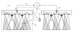
- FIG. 1A illustrates an example integrated lighting system.
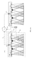
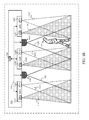
- FIG. 1B illustrates a portion of the example integrated lighting system depicted in FIG. 1A .
- the integrated lighting network 100 includes a plurality of integrated lighting systems 102 A, 102 B.
- Each integrated lighting system 102 A, 102 B can be communicatively coupled to each other, and each can include a plurality of optoelectronic modules 104 (e.g., 104 A, 104 B, 104 C) and a plurality of lighting fixtures 106 (e.g., 106 A, 106 B, 106 C, 106 D).
- the optoelectronic modules 104 is operable to collect data of an object 116 (e.g., a person, animal, or automotive vehicle), and the light fixtures 106 are operable to cast light of a particular intensity on the object 116 .
- the optoelectronic module 104 are operable to collect distance data, gesture data, 2D image data, 3D image data and/or proximity data of the object 116 .
- Each of the optoelectronic modules 104 can collect data by generating light over a field-of-illumination 119 (e.g., 119 A, 119 B, 119 C), and by collecting light over an at least partially overlapping fields-of-view 121 (e.g., 121 A, 121 B, 121 C).
- the light corresponds to the infrared portion of the electromagnetic spectrum.
- the light fixture 106 includes a light-emitting diode, a compact florescent, an incandescent light fixture or another light fixture operable to provide ambient lighting, task lighting, or other lighting, and is operable to cast light over a field of illumination 122 (e.g., 122 C, 122 D).
- the integrated lighting network 100 is operable to detect the object 116 via the integrated lighting systems 102 A, 102 B and to adjust a particular intensity of the light emitted by the light fixtures 106 .
- the object 116 can be a person walking under the integrated lighting systems 102 A, 102 B.
- the intensity of the light fixtures 106 can change so that the person's immediate position is illuminated while other positions along the person's walking path are not illuminated (i.e., the light fixtures 106 can be deactivated/turned off for those positions). Accordingly, electrical power can be used more efficiently.
- the integrated lighting systems 102 A, 102 B can be coupled communicatively to each other and to a cloud computing system 110 via one or more transceivers 108 .
- Each integrated lighting system 102 A, 102 B can be linked via the cloud in instances where the integrated lighting systems 102 A, 102 B are spread over large distances, and/or when data collected by the integrated lighting systems 102 A, 102 B is to be saved, analyzed, or processed in other ways (for applications where cloud computing is necessary or desirable).
- the integrated lighting systems 102 A, 102 B can be coupled communicatively to each other via two or more transceivers 108 (e.g., 108 A, 108 B).
- Data collected by the first integrated lighting system 102 A can be conveyed to the second integrated lighting system 102 B (directly or via the cloud computing system 110 ) and can influence the operation of the light fixtures 106 in one or both integrated lighting systems 102 A, 102 B.
- the velocity of the object 116 can be determined by the first integrated lighting system 102 A.
- This velocity data can be transmitted to the second integrated lighting system 102 B. Since the position of the first and second integrated lighting systems 102 A, 102 B are fixed with respect to each other, the velocity data can include estimates for when the object 116 will arrive under the second integrated lighting system 102 B. Accordingly, the intensity of the light fixture 106 , included within the second integrated lighting system 102 B, can be adjusted to illuminate the path of the object (e.g., just prior to) the arrival of the object 116 under the second lighting system 102 B.
- velocity data of an automotive vehicle can be communicated from the first integrated lighting system 102 A to the second integrated lighting system 102 B before the arrival of the automotive vehicle under the integrated lighting system 102 B. Consequently, light fixtures 106 included within the integrated lighting system 102 B can be activated before the automotive vehicle arrives at the area under the integrated lighting system 106 B (i.e., activated before the automotive vehicle is within the field-of-view 121 B). This aspect can improve both the efficiency and safety of highway/street lighting.
- the integrated lighting network 100 is operable to identify, or distinguish between, objects.
- the object 116 detected using the first integrated lighting system 102 A can be an automotive vehicle, and another object, such as a deer posing an imminent threat to the object 116 , can be identified using the second integrated lighting system 102 B.
- the shape, speed, or other characteristics of the object's movement can be collected by the optoelectronic module 104 B, wherein the optoelectronic module 104 B can include optical systems, image sensors, and 3D illuminators (e.g., structured-light illuminators).
- the data conveying the shape, speed, or other characteristics of the object's movement can be transmitted via the transceiver 108 to the cloud-computing system 110 and analyzed, wherein the object can be identified, for example, as a deer using object/shape analyzing algorithms. Commands appropriate for the particular scenario can then be directed to either or both of the integrated lighting systems 102 A, 102 B.
- the light fixture 106 of the second integrated lighting system 102 B can be activated so that the deer is illuminated, and/or the light fixture 106 of first integrated lighting system 102 A can be activated to flash in order to warn the automotive vehicle of the impending threat of the object (i.e., a deer in this example).
- each integrated lighting system is coupled communicatively to a computational device 114 such as a smartphone, tablet computer or laptop. In some implementations, each integrated lighting system is coupled communicatively to both a computational device 114 and a cloud computing system 110 .
- a warning message indicating the presence of an object posing an imminent threat can be directed to the computational device 114 .
- a customized lighting profile can be saved or loaded onto the computational device 114 and uploaded to the integrated lighting network 100 .
- the customized lighting profile can include specifications for particular lighting tasks.
- the integrated lighting network 100 can be distributed throughout a dwelling wherein the first integrated lighting system 102 A could be positioned in a first room (e.g., an audio-visual entertainment room), and the second lighting system 102 B could be positioned in a second room (e.g., a library).
- the customized lighting profile can include instructions for activating the light fixtures 106 within the first integrated lighting system 102 A with a particularly low illumination intensity (e.g., suitable for using an audio-visual entertainment device), and instructions for activating the light fixture 106 within the second integrated lighting system 102 B with a particularly high illumination intensity (e.g., suitable for reading).
- illumination intensity is included as an example, other characteristics of the light fixtures 106 can be modified via the customized lighting profile (e.g., color temperature).
- the integrated lighting systems 102 A, 102 B can be implemented on a small-scale.
- the integrated lighting systems 102 A, 102 B can be incorporated into the dashboard of an automotive vehicle or an audio-visual entertainment device (e.g., gaming system or television).
- the integrated lighting systems 102 A, 102 B can be incorporated into various controls and other components typically found on an automotive dashboard (e.g., air conditioning controls, navigation system controls, communication controls, or air conditioning vents).
- the lighting fixtures 106 included within the first integrated lighting system 102 A can be integrated within an air conditioning control knob, and the lighting fixtures 106 included within the second integrated lighting system 102 B can be integrated into an actuatable air-conditioning vent, for example.
- the object 116 may be an operator's hand.
- An action by the operator say reaching for the air conditioning knob, can activate the lighting fixtures 106 A, thereby illuminating the knob.
- another action by the operator may be anticipated, and directions or instructions can be sent (e.g., via the transceiver 108 and/or the cloud computing system 110 ) to the second integrated lighting system 102 B.
- the lighting fixture 106 B can illuminate the actuatable air-conditioning vent, thereby drawing the attention of the operator.
- any of the transceivers described above can include a blue-tooth enabled device or any other device enabled for wireless communication, such as devices employing magnetic-field communication, devices operable to communicate with a cellular network or mobile network, or any other radio-frequency based communication devices.
- the example integrated lighting systems described above, and components therein can further include components necessary for their respective functions such as power sources, processors, circuitry, drivers, firmware, bandpass filters, and so on, as would be apparent to a person of ordinary skill in the art in light of this disclosure.
- components necessary for their respective functions such as power sources, processors, circuitry, drivers, firmware, bandpass filters, and so on, as would be apparent to a person of ordinary skill in the art in light of this disclosure.
- example integrated lighting systems and methods for operating them are described in detail with reference to certain preferred implementations, other implementations are possible.
Landscapes
- Engineering & Computer Science (AREA)
- Computer Networks & Wireless Communication (AREA)
- Circuit Arrangement For Electric Light Sources In General (AREA)
Abstract
An integrated lighting system and integrated lighting network including integrated lighting systems are communicatively coupled to one another, for example, via various wireless transceivers. The systems and networks can collect data of a passing object (e.g., person, animal, automotive vehicle). The data can be transmitted over the systems and networks such that the intensity of light generated by light fixtures within the systems and networks can be adjusted to the activities of the particular object. In some cases, the data is distance data, gesture data, 2D image data, 3D image data and/or proximity data of the object.
Description
- Motion-activated lighting systems can be useful for many tasks requiring the efficient use of electrical power, such as illuminating a stairwell or hallway. These systems often include several illumination sources (e.g., a mercury-vapor lamp or a neon lamp) and, for each illumination source, an optoelectronic device (e.g., including an infrared emitter and detector) operable to detect the motion of an object within its field-of-view. Typically, the optoelectronic devices are unsophisticated by design and are only required to detect motion in to activate a corresponding illumination source.
- Such motion-activated lighting systems are ill-equipped for tasks, such as illuminating a path well-ahead of a moving object or optimizing illumination conditions (e.g., intensity) based on an object's location or activity. Systems operable to perform more complex tasks, such as those above, are needed.
- The present disclosure describes integrated lighting systems and networks operable to perform complex tasks. For example, in one aspect, an integrated lighting system includes an optoelectronic module, a light fixture and a transceiver. The optoelectronic module includes an emitter with an emitter field-of-illumination, and a detector with a detector field-of-view. The light fixture has a light fixture field-of-illumination. Further, the light fixture is communicatively coupled to the optoelectronic module. The transceiver is communicatively coupled to the light fixture and/or the optoelectronic module. The optoelectronic module is operable to collect data of an object, and the light fixture is operable to cast light of a particular intensity on the object.
- In another aspect, an integrated lighting network includes a plurality of integrated lighting systems, each of which is coupled to at least one corresponding optoelectronic module and at least one lighting fixture. Each optoelectronic module is operable to collect data of an object, and each light fixture is operable to cast light of a particular intensity on the object.
- Some implementations include one or more of the following features. For example, in some instances, the integrated lighting network includes integrated lighting systems communicatively coupled to a cloud computing system.
- In some instances, the integrated lighting network includes integrated lighting systems communicatively coupled to a computational device, such as a smartphone, a tablet computer, or a laptop.
- In some instances, the integrated lighting network is operable to collect data that corresponds to distance data, gesture data, 2D image data, 3D image data, and/or proximity data.
- In some instances, the integrated lighting network is operable to transmit the data to the cloud computing system, wherein the data can be used to configure a command directed to one of the plurality of light fixtures.
- In some instances, the integrated lighting network is operable to collect data via the time-of-flight technique.
- Other aspects, features and advantages will be readily apparent from the following description, the accompanying drawings and the claims.
-
FIG. 1A illustrates an example integrated lighting system. -
FIG. 1B illustrates a portion of the example integrated lighting system depicted inFIG. 1A . - An
integrated lighting network 100 is depicted inFIG. 1A , and a portion of the integratedlighting network 100 is depicted inFIG. 1B . The integratedlighting network 100 includes a plurality of integratedlighting systems lighting system object 116. In some implementations, the optoelectronic module 104 are operable to collect distance data, gesture data, 2D image data, 3D image data and/or proximity data of theobject 116. Each of the optoelectronic modules 104 can collect data by generating light over a field-of-illumination 119 (e.g., 119A, 119B, 119C), and by collecting light over an at least partially overlapping fields-of-view 121 (e.g., 121A, 121B, 121C). In some instances, the light corresponds to the infrared portion of the electromagnetic spectrum. In some implementations, the light fixture 106 includes a light-emitting diode, a compact florescent, an incandescent light fixture or another light fixture operable to provide ambient lighting, task lighting, or other lighting, and is operable to cast light over a field of illumination 122 (e.g., 122C, 122D). - In general, the integrated
lighting network 100 is operable to detect theobject 116 via the integratedlighting systems object 116 can be a person walking under the integratedlighting systems - The integrated
lighting systems cloud computing system 110 via one ormore transceivers 108. Each integratedlighting system lighting systems lighting systems lighting systems - Data collected by the first integrated
lighting system 102A can be conveyed to the second integratedlighting system 102B (directly or via the cloud computing system 110) and can influence the operation of the light fixtures 106 in one or both integratedlighting systems object 116 can be determined by the first integratedlighting system 102A. This velocity data can be transmitted to the second integratedlighting system 102B. Since the position of the first and second integratedlighting systems object 116 will arrive under the second integratedlighting system 102B. Accordingly, the intensity of the light fixture 106, included within the second integratedlighting system 102B, can be adjusted to illuminate the path of the object (e.g., just prior to) the arrival of theobject 116 under thesecond lighting system 102B. - The foregoing example can be extended to other objects including automotive vehicles. For example, velocity data of an automotive vehicle can be communicated from the first integrated
lighting system 102A to the second integratedlighting system 102B before the arrival of the automotive vehicle under the integratedlighting system 102B. Consequently, light fixtures 106 included within the integratedlighting system 102B can be activated before the automotive vehicle arrives at the area under the integratedlighting system 106B (i.e., activated before the automotive vehicle is within the field-of-view 121B). This aspect can improve both the efficiency and safety of highway/street lighting. - In some instances, such as in the foregoing example, the
integrated lighting network 100 is operable to identify, or distinguish between, objects. For example, theobject 116 detected using the first integratedlighting system 102A can be an automotive vehicle, and another object, such as a deer posing an imminent threat to theobject 116, can be identified using the second integratedlighting system 102B. In such instances, the shape, speed, or other characteristics of the object's movement can be collected by theoptoelectronic module 104B, wherein theoptoelectronic module 104B can include optical systems, image sensors, and 3D illuminators (e.g., structured-light illuminators). The data conveying the shape, speed, or other characteristics of the object's movement can be transmitted via thetransceiver 108 to the cloud-computing system 110 and analyzed, wherein the object can be identified, for example, as a deer using object/shape analyzing algorithms. Commands appropriate for the particular scenario can then be directed to either or both of the integratedlighting systems lighting system 102B can be activated so that the deer is illuminated, and/or the light fixture 106 of first integratedlighting system 102A can be activated to flash in order to warn the automotive vehicle of the impending threat of the object (i.e., a deer in this example). - In some implementations, each integrated lighting system is coupled communicatively to a
computational device 114 such as a smartphone, tablet computer or laptop. In some implementations, each integrated lighting system is coupled communicatively to both acomputational device 114 and acloud computing system 110. A warning message indicating the presence of an object posing an imminent threat, such as the deer in the foregoing example, can be directed to thecomputational device 114. - In some implementations, a customized lighting profile can be saved or loaded onto the
computational device 114 and uploaded to theintegrated lighting network 100. The customized lighting profile can include specifications for particular lighting tasks. For example, theintegrated lighting network 100 can be distributed throughout a dwelling wherein the firstintegrated lighting system 102A could be positioned in a first room (e.g., an audio-visual entertainment room), and thesecond lighting system 102B could be positioned in a second room (e.g., a library). The customized lighting profile can include instructions for activating the light fixtures 106 within the firstintegrated lighting system 102A with a particularly low illumination intensity (e.g., suitable for using an audio-visual entertainment device), and instructions for activating the light fixture 106 within the secondintegrated lighting system 102B with a particularly high illumination intensity (e.g., suitable for reading). Though illumination intensity is included as an example, other characteristics of the light fixtures 106 can be modified via the customized lighting profile (e.g., color temperature). - In some instances, the
integrated lighting systems integrated lighting systems integrated lighting systems integrated lighting system 102A can be integrated within an air conditioning control knob, and the lighting fixtures 106 included within the secondintegrated lighting system 102B can be integrated into an actuatable air-conditioning vent, for example. In some instances, theobject 116 may be an operator's hand. An action by the operator, say reaching for the air conditioning knob, can activate thelighting fixtures 106A, thereby illuminating the knob. In some instances, another action by the operator may be anticipated, and directions or instructions can be sent (e.g., via thetransceiver 108 and/or the cloud computing system 110) to the secondintegrated lighting system 102B. For example, thelighting fixture 106B can illuminate the actuatable air-conditioning vent, thereby drawing the attention of the operator. - Any of the transceivers described above can include a blue-tooth enabled device or any other device enabled for wireless communication, such as devices employing magnetic-field communication, devices operable to communicate with a cellular network or mobile network, or any other radio-frequency based communication devices.
- The example integrated lighting systems described above, and components therein (e.g., optoelectronic modules and audio devices), can further include components necessary for their respective functions such as power sources, processors, circuitry, drivers, firmware, bandpass filters, and so on, as would be apparent to a person of ordinary skill in the art in light of this disclosure. Further, although example integrated lighting systems and methods for operating them are described in detail with reference to certain preferred implementations, other implementations are possible.
- In the foregoing description and in the accompanying drawings, reference is made to particular features. However, all possible combinations of such particular features are included within the scope of this description. For example, where a particular feature is disclosed in the context of a particular aspect or embodiment, that feature also can be used, as appropriate, in combination with and/or in the context of other aspects and together with other features.
- Moreover, various features disclosed in this disclosure may be replaced by alternative features serving the same, equivalent, or similar purpose, unless expressly stated otherwise. Thus, unless expressly stated otherwise, each feature disclosed is one example only of a generic series of equivalent or similar features. Therefore, other implementations are within the scope of the claims.
Claims (14)
1. An integrated lighting system comprising:
an optoelectronic module including an emitter having an emitter field-of-illumination, and a detector having a detector field-of-view;
a light fixture having a light fixture field-of-illumination, the light fixture being coupled communicatively to the optoelectronic module; and
a transceiver communicatively coupled to the light fixture and/or the optoelectronic module;
wherein the optoelectronic module is operable to collect data of an object, and the light fixture is operable to cast light of a particular intensity on the object, and the transceiver is operable to transmit data of the object.
2. The integrated lighting system as in claim 1 , wherein the data corresponds to distance data, gesture data, 2D image data, 3D image data, and/or proximity data.
3. The integrated lighting system as in claim 2 , wherein the light of the particular intensity corresponds to data collected by the optoelectronic module.
4. The integrated lighting system as in claim 1 , wherein the light fixtures are operable to provide a particular intensity of light corresponding to data of the object.
5. The integrated lighting system as in claim 1 , wherein the optoelectronic module is operable to collect data via a time-of-flight technique.
6. An integrated lighting network comprising:
a plurality of integrated lighting systems communicatively coupled to one another,
wherein each of the integrated lighting systems includes a plurality of optoelectronic modules and a plurality of lighting fixtures,
the plurality of optoelectronic modules being operable to collect data of an object, and the plurality of light fixtures being operable to cast light of a respective particular intensity on the object.
7. The integrated lighting network of claim 6 , wherein each of the integrated lighting systems is communicatively coupled to a cloud computing system.
8. The integrated lighting network as in claim 7 , wherein the data collected by one of the optoelectronic modules in a first integrated lighting system is transmitted to a cloud computing system operable to transform the data into a command that is directed to a light fixture in a second integrated lighting system.
9. The integrated lighting network of claim 6 , wherein each of the integrated lighting systems is communicatively coupled to a computational device.
10. The integrated lighting network as in claim 9 , wherein the computational device is a smartphone, a tablet computer, or a laptop.
11. The integrated lighting network as in claim 6 , wherein the data corresponds to distance data, gesture data, 2D image data, 3D image data, and/or proximity data.
12. The integrated lighting network as in claim 11 , wherein the light of the particular intensity corresponds to data collected by one or more of the optoelectronic modules.
13. The integrated lighting network as in claim 2 , wherein the light fixtures are operable to provide a particular intensity of light corresponding to data of the object.
14. The integrated lighting network as in claim 2 , in which at least one of the optoelectronic modules is operable to collect data via a time-of-flight technique.
Priority Applications (1)
| Application Number | Priority Date | Filing Date | Title |
|---|---|---|---|
| US15/715,556 US20180098407A1 (en) | 2016-09-30 | 2017-09-26 | Integrated lighting system and network |
Applications Claiming Priority (2)
| Application Number | Priority Date | Filing Date | Title |
|---|---|---|---|
| US201662402538P | 2016-09-30 | 2016-09-30 | |
| US15/715,556 US20180098407A1 (en) | 2016-09-30 | 2017-09-26 | Integrated lighting system and network |
Publications (1)
| Publication Number | Publication Date |
|---|---|
| US20180098407A1 true US20180098407A1 (en) | 2018-04-05 |
Family
ID=61758641
Family Applications (1)
| Application Number | Title | Priority Date | Filing Date |
|---|---|---|---|
| US15/715,556 Abandoned US20180098407A1 (en) | 2016-09-30 | 2017-09-26 | Integrated lighting system and network |
Country Status (1)
| Country | Link |
|---|---|
| US (1) | US20180098407A1 (en) |
Cited By (6)
| Publication number | Priority date | Publication date | Assignee | Title |
|---|---|---|---|---|
| US10349501B1 (en) * | 2018-07-31 | 2019-07-09 | Lexmark International, Inc. | System and methods for locating an asset in an environment |
| US20200207263A1 (en) * | 2018-12-26 | 2020-07-02 | Nifco Korea Inc. | Lighting device for automobile air vent |
| US11139271B2 (en) | 2018-08-24 | 2021-10-05 | Samsung Electronics Co., Ltd. | Semiconductor device and method of fabricating the same |
| US20210352791A1 (en) * | 2020-05-11 | 2021-11-11 | Wangs Alliance Corporation | Fixtures, Power and Control Systems for Same |
| US11174674B1 (en) * | 2018-03-16 | 2021-11-16 | Newtonoid Technologies, L.L.C. | Lighted interface |
| US20230363068A1 (en) * | 2020-09-14 | 2023-11-09 | Signify Holding B.V. | A lighting controller |
Citations (4)
| Publication number | Priority date | Publication date | Assignee | Title |
|---|---|---|---|---|
| US20140112537A1 (en) * | 2011-06-10 | 2014-04-24 | Flir Systems, Inc. | Systems and methods for intelligent monitoring of thoroughfares using thermal imaging |
| US20160198548A1 (en) * | 2013-08-27 | 2016-07-07 | Philips Lighting Holding B.V. | Sensor network with adaptive detection settings based on the status information from neighboring luminaires and/or connected devices |
| US20160302284A1 (en) * | 2015-04-10 | 2016-10-13 | Google Inc. | Dynamic pathlight brightness based on size and distance of motion/object approaching the device |
| US20160345414A1 (en) * | 2014-01-30 | 2016-11-24 | Philips Lighting Holding B.V. | Controlling a lighting system using a mobile terminal |
-
2017
- 2017-09-26 US US15/715,556 patent/US20180098407A1/en not_active Abandoned
Patent Citations (4)
| Publication number | Priority date | Publication date | Assignee | Title |
|---|---|---|---|---|
| US20140112537A1 (en) * | 2011-06-10 | 2014-04-24 | Flir Systems, Inc. | Systems and methods for intelligent monitoring of thoroughfares using thermal imaging |
| US20160198548A1 (en) * | 2013-08-27 | 2016-07-07 | Philips Lighting Holding B.V. | Sensor network with adaptive detection settings based on the status information from neighboring luminaires and/or connected devices |
| US20160345414A1 (en) * | 2014-01-30 | 2016-11-24 | Philips Lighting Holding B.V. | Controlling a lighting system using a mobile terminal |
| US20160302284A1 (en) * | 2015-04-10 | 2016-10-13 | Google Inc. | Dynamic pathlight brightness based on size and distance of motion/object approaching the device |
Cited By (11)
| Publication number | Priority date | Publication date | Assignee | Title |
|---|---|---|---|---|
| US11174674B1 (en) * | 2018-03-16 | 2021-11-16 | Newtonoid Technologies, L.L.C. | Lighted interface |
| US10349501B1 (en) * | 2018-07-31 | 2019-07-09 | Lexmark International, Inc. | System and methods for locating an asset in an environment |
| US11139271B2 (en) | 2018-08-24 | 2021-10-05 | Samsung Electronics Co., Ltd. | Semiconductor device and method of fabricating the same |
| US11705435B2 (en) | 2018-08-24 | 2023-07-18 | Samsung Electronics Co., Ltd. | Semiconductor device and method of fabricating the same |
| US12009346B2 (en) | 2018-08-24 | 2024-06-11 | Samsung Electronics Co., Ltd. | Semiconductor device and method of fabricating the same |
| US20200207263A1 (en) * | 2018-12-26 | 2020-07-02 | Nifco Korea Inc. | Lighting device for automobile air vent |
| US10793062B2 (en) * | 2018-12-26 | 2020-10-06 | Nifco Korea Inc. | Lighting device for automobile air vent |
| US20210352791A1 (en) * | 2020-05-11 | 2021-11-11 | Wangs Alliance Corporation | Fixtures, Power and Control Systems for Same |
| US11649953B2 (en) * | 2020-05-11 | 2023-05-16 | Wangs Alliance Corporation | Fixtures, power and control systems for same |
| US20230363068A1 (en) * | 2020-09-14 | 2023-11-09 | Signify Holding B.V. | A lighting controller |
| US12432834B2 (en) * | 2020-09-14 | 2025-09-30 | Signify Holding B.V. | Lighting controller |
Similar Documents
| Publication | Publication Date | Title |
|---|---|---|
| US20180098407A1 (en) | Integrated lighting system and network | |
| US10571933B2 (en) | Unmanned aerial vehicles | |
| US9131547B2 (en) | Illumination device and illumination system | |
| US10078961B2 (en) | Method and device for operating a traffic-infrastructure unit including a signal source | |
| JP7235659B2 (en) | Vehicle lighting system and vehicle | |
| KR101768589B1 (en) | Control device mounted on vehicle and method for controlling the same | |
| EP3071988B1 (en) | Methods and apparatus for light-based positioning and navigation | |
| EP2529975A2 (en) | Light distribution pattern control using object detection and electrowetting lenses | |
| US20150088373A1 (en) | Optical communications and obstacle sensing for autonomous vehicles | |
| EP3543121B1 (en) | Object tracking illumination system | |
| JP2016535418A5 (en) | ||
| HK1246743A1 (en) | Tracking and lighting systems and methods for a vehicle | |
| CN107199943B (en) | Intelligent lamp assembly and intelligent lighting system for motor vehicle | |
| US20190325749A1 (en) | Illuminating device, illuminating guidance system and illuminating guidance method | |
| KR20170004508A (en) | Method and apparaus for automatic landing of aircraft using vision-based information | |
| US10634299B2 (en) | Motion sensor based lighting fixture operation | |
| KR101671993B1 (en) | Safety system for vehicle | |
| JP2015213041A5 (en) | ||
| CN204155294U (en) | Desktop intelligent identifying system | |
| TWM519371U (en) | Illumination control system and illumination control apparatus | |
| US10488856B2 (en) | Method for monitoring an environment of a vehicle | |
| KR102807174B1 (en) | Electronic device of vehicle for detecting object and operating method thereof | |
| WO2015160434A1 (en) | Adaptive roadway light | |
| CN107940325A (en) | Intelligent constant lighting system | |
| CN107123293A (en) | Method and apparatus for non-driver traveling of the signalling motor vehicle in parking lot |
Legal Events
| Date | Code | Title | Description |
|---|---|---|---|
| STCB | Information on status: application discontinuation |
Free format text: ABANDONED -- FAILURE TO RESPOND TO AN OFFICE ACTION |