US20180098212A1 - Device network status information - Google Patents
Device network status information Download PDFInfo
- Publication number
- US20180098212A1 US20180098212A1 US15/726,049 US201715726049A US2018098212A1 US 20180098212 A1 US20180098212 A1 US 20180098212A1 US 201715726049 A US201715726049 A US 201715726049A US 2018098212 A1 US2018098212 A1 US 2018098212A1
- Authority
- US
- United States
- Prior art keywords
- status information
- log
- piece
- response
- broadcast
- Prior art date
- Legal status (The legal status is an assumption and is not a legal conclusion. Google has not performed a legal analysis and makes no representation as to the accuracy of the status listed.)
- Granted
Links
Images


Classifications
-
- H—ELECTRICITY
- H04—ELECTRIC COMMUNICATION TECHNIQUE
- H04W—WIRELESS COMMUNICATION NETWORKS
- H04W8/00—Network data management
- H04W8/22—Processing or transfer of terminal data, e.g. status or physical capabilities
- H04W8/24—Transfer of terminal data
-
- H—ELECTRICITY
- H04—ELECTRIC COMMUNICATION TECHNIQUE
- H04W—WIRELESS COMMUNICATION NETWORKS
- H04W8/00—Network data management
- H04W8/22—Processing or transfer of terminal data, e.g. status or physical capabilities
-
- H—ELECTRICITY
- H04—ELECTRIC COMMUNICATION TECHNIQUE
- H04W—WIRELESS COMMUNICATION NETWORKS
- H04W4/00—Services specially adapted for wireless communication networks; Facilities therefor
- H04W4/06—Selective distribution of broadcast services, e.g. multimedia broadcast multicast service [MBMS]; Services to user groups; One-way selective calling services
-
- H—ELECTRICITY
- H04—ELECTRIC COMMUNICATION TECHNIQUE
- H04L—TRANSMISSION OF DIGITAL INFORMATION, e.g. TELEGRAPHIC COMMUNICATION
- H04L41/00—Arrangements for maintenance, administration or management of data switching networks, e.g. of packet switching networks
- H04L41/08—Configuration management of networks or network elements
- H04L41/085—Retrieval of network configuration; Tracking network configuration history
- H04L41/0853—Retrieval of network configuration; Tracking network configuration history by actively collecting configuration information or by backing up configuration information
-
- H—ELECTRICITY
- H04—ELECTRIC COMMUNICATION TECHNIQUE
- H04L—TRANSMISSION OF DIGITAL INFORMATION, e.g. TELEGRAPHIC COMMUNICATION
- H04L43/00—Arrangements for monitoring or testing data switching networks
- H04L43/08—Monitoring or testing based on specific metrics, e.g. QoS, energy consumption or environmental parameters
-
- H04L65/4076—
-
- H—ELECTRICITY
- H04—ELECTRIC COMMUNICATION TECHNIQUE
- H04L—TRANSMISSION OF DIGITAL INFORMATION, e.g. TELEGRAPHIC COMMUNICATION
- H04L65/00—Network arrangements, protocols or services for supporting real-time applications in data packet communication
- H04L65/60—Network streaming of media packets
- H04L65/61—Network streaming of media packets for supporting one-way streaming services, e.g. Internet radio
- H04L65/611—Network streaming of media packets for supporting one-way streaming services, e.g. Internet radio for multicast or broadcast
-
- H—ELECTRICITY
- H04—ELECTRIC COMMUNICATION TECHNIQUE
- H04L—TRANSMISSION OF DIGITAL INFORMATION, e.g. TELEGRAPHIC COMMUNICATION
- H04L67/00—Network arrangements or protocols for supporting network services or applications
- H04L67/01—Protocols
- H04L67/12—Protocols specially adapted for proprietary or special-purpose networking environments, e.g. medical networks, sensor networks, networks in vehicles or remote metering networks
- H04L67/125—Protocols specially adapted for proprietary or special-purpose networking environments, e.g. medical networks, sensor networks, networks in vehicles or remote metering networks involving control of end-device applications over a network
-
- H—ELECTRICITY
- H04—ELECTRIC COMMUNICATION TECHNIQUE
- H04L—TRANSMISSION OF DIGITAL INFORMATION, e.g. TELEGRAPHIC COMMUNICATION
- H04L67/00—Network arrangements or protocols for supporting network services or applications
- H04L67/50—Network services
- H04L67/51—Discovery or management thereof, e.g. service location protocol [SLP] or web services
-
- H—ELECTRICITY
- H04—ELECTRIC COMMUNICATION TECHNIQUE
- H04L—TRANSMISSION OF DIGITAL INFORMATION, e.g. TELEGRAPHIC COMMUNICATION
- H04L41/00—Arrangements for maintenance, administration or management of data switching networks, e.g. of packet switching networks
- H04L41/04—Network management architectures or arrangements
- H04L41/046—Network management architectures or arrangements comprising network management agents or mobile agents therefor
-
- H—ELECTRICITY
- H04—ELECTRIC COMMUNICATION TECHNIQUE
- H04L—TRANSMISSION OF DIGITAL INFORMATION, e.g. TELEGRAPHIC COMMUNICATION
- H04L41/00—Arrangements for maintenance, administration or management of data switching networks, e.g. of packet switching networks
- H04L41/08—Configuration management of networks or network elements
- H04L41/0803—Configuration setting
- H04L41/0813—Configuration setting characterised by the conditions triggering a change of settings
- H04L41/082—Configuration setting characterised by the conditions triggering a change of settings the condition being updates or upgrades of network functionality
-
- H04W4/008—
-
- H—ELECTRICITY
- H04—ELECTRIC COMMUNICATION TECHNIQUE
- H04W—WIRELESS COMMUNICATION NETWORKS
- H04W4/00—Services specially adapted for wireless communication networks; Facilities therefor
- H04W4/70—Services for machine-to-machine communication [M2M] or machine type communication [MTC]
-
- H—ELECTRICITY
- H04—ELECTRIC COMMUNICATION TECHNIQUE
- H04W—WIRELESS COMMUNICATION NETWORKS
- H04W4/00—Services specially adapted for wireless communication networks; Facilities therefor
- H04W4/80—Services using short range communication, e.g. near-field communication [NFC], radio-frequency identification [RFID] or low energy communication
Definitions
- the present invention relates to status information in a device network.
- the evolvement of communication technology has enabled versatile communication possibilities and introduction of different services.
- An example of such a service is a remote support for maintenance staff of machines and equipment.
- smartphone applications that allow a user of the smartphone to receive status information of a machine from the machine over a Bluetooth connection, for example.
- Some embodiments provide a method, a device, a system and a computer program product for providing possibility to obtain status information on plurality of devices by connecting to one device.
- FIG. 1 shows simplified architecture of a system
- FIG. 2 shows a simplified block diagram of a device
- FIGS. 3 to 7 are flow charts illustrating exemplary functionalities
- FIGS. 8 and 9 illustrate exemplary information exchanges
- FIG. 10 is a block diagram of an exemplary device.
- the present invention is applicable to any device that is configurable to receive, transmit and store status information, and a system comprising such devices.
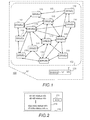
- FIG. 1 An extremely general architecture of an exemplary system 100 is illustrated in FIG. 1 .
- FIG. 1 is a simplified system architecture only showing some elements, functional entities, which are logical units whose implementation may differ from what is shown, and some equipment. It is apparent to a person skilled in the art that the system comprises any number of shown elements, other equipment, and structures that are not illustrated.
- the system 100 comprises one or more sites 101 (only one illustrated in FIG. 1 ) comprising one or more device networks 102 formed by devices 110 at a site and one or more user apparatuses 120 (only one illustrated in FIG. 1 ) that may enter the site 101 .
- the system may comprise one or more service centers, remote and/or local, and one or more networks over which one or more devices 110 at the site and/or the one or more user apparatuses 120 may connect to the one or more service centers.
- the service center(s) and the network(s) over which to connect to the service center(s) are not described in more detail herein since the focus is in functionality at the site.
- the user apparatus 120 refers to a computing device (equipment), that may be a non-portable device or a portable device, and it may also be referred to as a user terminal or user device.
- Portable computing devices include wireless mobile communication devices operating with or without a subscriber identification module (SIM) in hardware or in software, including, but not limited to, the following types of devices: mobile phone, smart-phone, personal digital assistant (PDA), laptop and/or touch screen computer, tablet (tablet computer), multimedia device, and wearable devices.
- SIM subscriber identification module
- the user apparatus 120 is configured to establish connections to the devices at the site, and to acquire/retrieve different information, such as status information on a device via a corresponding interface. To display status information on multiple devices, for example as illustrated below with FIGS.
- the user apparatus 120 may comprise a remote maintenance application, for example, as a mobile app, that comprises as part of the application, or as an add-in or a plug-in to the application, an enhanced status view display unit (e-s-w-u) 121 , for remote maintenance purpose.
- a remote maintenance application for example, as a mobile app, that comprises as part of the application, or as an add-in or a plug-in to the application, an enhanced status view display unit (e-s-w-u) 121 , for remote maintenance purpose.
- the configuration of the user apparatus may be according to prior art, or any future corresponding configuration may be used.
- the site 101 is a cluster or a farm or a fleet of devices 110 , and the devices may be of same type, as illustrated in FIG. 1 , or the cluster/farm/fleet of devices may comprise different types of devices.
- the site 101 may be an industrial site, a residential site, or a commercial site, and any combination thereof.
- the devices 110 , or some of the devices 110 , at the site 101 may locate near each other, and/or the distance between the devices 110 , or between some of the devices 110 , may be rather long. For example, devices may locate rather near to each other in a factory but in an offshore wind farm at least some of the devices may locate rather far away from each other.
- the devices 110 at the site 101 form a device network 102 , i.e. a local network, in which a device is connectable at least to one other device over a local connection.
- the device network 102 may be a mesh network. Examples of such local connections are depicted in FIG. 1 by double-headed arrows, one of which is indicated also by a reference number 103 .
- the local connection may be a direct connection, for example a Bluetooth connection, or a connection over a local wireless network, like Wi-Fi or Li-Fi, or a wired connection using Ethernet, for example. Naturally the connection may be provided by any mobile system, such as GSM, GPRS, LTE, 4G, 5G and beyond.
- the local connection may be based on any existing or future communication technology, any connection type over which data may be transmitted, may be used, and the local connections in the device network may be of different type.
- any connection type over which data may be transmitted may be used, and the local connections in the device network may be of different type.
- the local connections in the device network may be of different type.
- all local connections may use Bluetooth, whereas in the offshore wind farm, some connections may use Bluetooth and some may be wired connections.
- the plurality of devices 110 whose status information may be acquired/requested are depicted as drives.
- the drives in FIG. 1 depict any device, machine, equipment, system and a process whose status information, such as one or more parameters or their values, may be acquired/requested via an interface.
- Other examples of such equipment include frequency converters, AC/DC modules, DC/AC modules, programmable logic controllers, switches, motion controllers or motion drives, servo motors, soft starters, robots, wind turbines, solar panels, solar inverters, and heavy equipment, etc. It should be appreciated that in the above only some examples are listed.
- FIG. 1 a plurality of devices 110 is illustrated, it should be appreciated that a device network 102 may be created by two devices 110 .
- FIG. 2 is a block diagram illustrating some entities in an exemplified device that is configurable to manage status information.
- the device 210 is configured to provide status information on the entire device network whereto the device 210 belongs when status information of the device is requested/inquired.
- the device 210 comprises a status information unit (s-i-u) 211 configured to maintain status information in a memory 212 and to cause sending of different status information related messages, or corresponding pieces of information, as will be described in more detail below with FIGS. 3 to 9 .
- the memory 212 comprises the entire device network status information as a single log file (log).
- the log comprises status information on all devices in the device network.
- the log may be divided into different parts. For example, there may be a part for status information of the device, and another part for status information of other devices in the device network, and/or there may be a part for latest status information and a part for history status information. In other words, any internal structure for the status information may be used.
- the log may comprise only the latest status information, only certain amount of latest status information per device, such as three latest, four latest, etc., and/or there may be an age limit to the status information in the log file, and/or the log may comprise history information.
- the log may comprise history information.
- Naturally more status information of the device 210 may be maintained than what is maintained on other devices in the device network. For example, as depicted in FIG. 2 , for a device D 1 there are two different status information (status info and status info-a), whereas for the other devices only one status information is maintained.
- the status information may comprise any kind of information on use, events, operation environment, lifetime status, etc.
- status information include events, faults, warnings, other results of operation monitoring, such as usage time (current, average, max, etc.), estimated time to a next maintenance, which component should be changed, estimation which component will fail next, a value exceeding a limit, a value being below a minimum limit, and inhibits, for example reason(s) why a device cannot start, different parameters and/or their values, such as temperature (current, average, min, max, cycles), average temperature, environmental temperature, humidity, vibration, etc., just to list some examples in a non-exhaustive manner.
- the status information of a device may comprise only one piece of information, or any amount of pieces of information. The choice what constitutes the status information may depend on devices in the device network, it may be different for different devices in the device network, and there are no restrictions; one or more pieces of information obtainable from a device may be set to be part of the status information.
- the device 210 or more precisely the status information unit 211 , are described using a frame as an example of a digital data transmission unit, without limiting the examples to a use of a frame. It is a straightforward process to implement the examples to any other kind of a transmission unit.
- status is used for a piece of status information determined for a device at a certain moment, according to settings of the device. It should be appreciated that any settings may be used, including what constitutes the status, and how often it is determined and/or what triggers the determination of the status.
- FIG. 3 illustrates an exemplary functionality of a device at a site, or more precisely an exemplary functionality of the status information unit, relating to status information of the device.
- the exemplified functionality illustrated in FIG. 3 starts when a status of the device is to be determined.
- the status information unit determines in step 302 an identifier for the determined status, called below status identifier.
- the status identifier comprises at least a variable part that may be a time stamp indicating the time the status is determined in step 301 , or a running number, for example.
- the status identifier may comprise as a fixed part an identifier of the device, which identifies the device uniquely at least in the device network. The purpose of the status identifier is to separate different statuses, as will become evident with FIG. 5 . However, there may be implementations without a status identifier, or at least its variable part, for example in implementations using message with a certain life time, set by the message originator.
- the status is stored in step 303 to the memory, to be part of the corresponding status information.
- the status information is stored with the status identifier (i.e. associated with the status identifier), or with the variable part of the status identifier or without the status identifier, either to the log or to a device-specific part of the log in the memory, and it may replace an older status information or just be added to form history status information.
- a frame is created in step 304 , and the status identifier and the status are added to the frame, and broadcast of the frame is caused in step 305 to all devices within its range, i.e. to devices with which the device has a connection or in a non-connected mode to all devices that are near enough to receive the broadcast. If the identifier does not contain the fixed part, i.e. the identifier of the originating device, the identifier of the device is added to the frame, either to a header or to a body, or the originating device is indicated according to the used broadcast communication technology.
- Broadcasting may be performed by sending advertisements, or any corresponding frames that can be sent and received in a non-connected mode. Broadcasting may also be performed by forwarding the frame over each connection the device has, for example using flooding type of multi-hop broadcast or bridging, or a combination of broadcast and convergecasting. In other words, any kind of broadcast may be used.
- FIG. 4 illustrates another an exemplary functionality of a device at a site, or more precisely an exemplary functionality of the status information unit, relating to status information of the device.
- the device or more precisely the status information unit, is configured to broadcast its status when the status changes, or at certain intervals, called broadcast intervals. Further, in the example it is assumed that the status is determined at certain intervals, called status intervals.
- the status intervals are shorter than the broadcast intervals, and the broadcast interval may be a multiple of the status interval, but that need not to be the case.
- the device may be configured, for example, have a separate unit, or the status information unit may be configured to analyse and determine status, detect a fault or a warning, etc. This may be achieved by monitoring and/or by using one or more criteria/rules. For example, if a value is above or below a threshold, activation of a safety function, such as safe-torque-off, is activated.
- a safety function such as safe-torque-off
- step 401 it is monitored in step 401 , whether or not it is time to determine the status of the device.
- the status is determined in step 402 and stored to the memory, as described above.
- a frame containing the status information is created in step 404 , the creating including, if not performed in step 402 , generating/determining an identifier, as described above, and broadcast of the frame is caused in step 404 , as described above.
- the broadcast preferably causes resetting a counter monitoring the broadcast interval, in which case the broadcast interval ensures a fixed interval between two status broadcast without any change.
- the counter monitoring the broadcast interval may be independent of the broadcast caused by a change, in which case the counter is not resat when a change causes broadcast of the status. Then the process proceeds to step 401 to wait for the next time to determine the status of the device.
- step 404 it is checked in step 404 , whether or not it is time to broadcast the status. In other words, it is checked, whether or not the time lapsed from the last broadcast exceeds the broadcast time interval, or is the same as the broadcast time interval. If the time lapsed from the last broadcast is smaller than the broadcast time interval, it is not time to broadcast the status (step 405 : no), and the process proceeds to step 401 to wait for the next time to determine the status of the device. If it is time to broadcast the status (step 405 : yes), the process proceeds to step 404 to create and cause broadcast of a frame containing the status information. As said above, the time from the last broadcast may be monitored from the actual last broadcast, or from previous broadcast caused by the time exceeding the broadcast interval.
- FIG. 5 illustrates an exemplary functionality of a device at a site, or more precisely an exemplary functionality of the status information unit, relating to status information of other devices.
- an identifier (a status identifier) in the frame is extracted, or otherwise determined in step 502 .
- the frame originator i.e. the device whose status is in the frame
- the variable part are determined.
- the status identifier is then compared in step 503 to status identifiers in the log to find out, whether or not the status identifier, and thereby also the status in the frame, is a new one.
- the comparison may comprise sub-steps including determining whether the device who receives the frame is also the originator, and if it is, determining, without comparing the variable part, or the status identifiers, that the status identifier is not a new one.
- the log is updated in step 504 to contain the status information in the frame.
- the status information is stored with the status identifier (i.e. associated with the status identifier), to the log, and depending on an implementation the status may replace an older status information of the same originating device or just be added to form history status information.
- step SOS broadcast of the frame is caused in step SOS.
- the frame is replicated, if necessary, and forwarded over each local connection, and/or advertised, as described above with FIG. 3 .
- the frame may be send or not send back in step 505 to the device wherefrom it was received in step 501 .
- step 503 If the identifier is not a new one (step 503 : no), it has been received earlier, or it is a frame originating from the device and containing its status information, and therefore the frame is ignored in step 506 . In other words, it is not forwarded any more. Thanks to this, unnecessary re-circulation of the frames is avoided while by step 505 it is ensured that all frames reach all devices in the device network.
- FIG. 6 illustrates an exemplary functionality of a device at a site, or more precisely an exemplary functionality of the status information unit, relating to status information enquiries.
- step 601 when a status enquiry is received in step 601 , sending of the status information in the log is caused in step 602 .
- a default setting may be that always all the information in the log is sent. However, it should be appreciated that also only part of the information in the log, such as only the newest information per device, may be sent. Hence, an enquiry to one device results to receiving status information on all devices in the device network.
- FIG. 7 illustrates another exemplary functionality of a device at a site, or more precisely an exemplary functionality of the status information unit, relating to status information enquiries.
- there exists two different kind of status enquiries one for requesting status information on all the devices in the device network, and one for requesting status information on the device who receives the enquiry.
- step 701 when a status enquiry is received in step 701 , the type of the enquiry is checked in step 702 . If the enquiry is for all devices (step 702 : yes), sending of the status information in the log is caused in step 703 . In other words, status information on all the devices in the device network is sent.
- step 704 sending status information of the device is caused in step 704 . For example, if the log contains a certain amount of statuses, and there is a separate history log for the device, in step 704 sending also the history log is caused, whereas in step 703 the history log may not be in the sent status information.
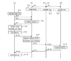
- FIG. 8 illustrates information exchange in an exemplary situation.
- the remote application unit includes the enhanced status view display unit and no difference which unit performs which part is made, since the division bears no significance, the result being the same.
- devices D 1 to Dx or more precisely, corresponding status information units, at a site broadcast in messages 8 - 1 status information, either own or others, and update their logs (point 8 - 2 ) correspondingly, as described above with FIGS. 2 to 5 .
- a user apparatus UA enters the site, and the user turns on a remote application.
- the remote application causes the user apparatus to establish a connection (messages 8 - 4 ) to the nearest device, which in the example is the device D 1 .
- the remote application causes the user apparatus to request (message 8 - 5 ) status information from the device D 1 .
- the device D 1 Upon receiving the request, the device D 1 , or more precisely the status information unit, detects in point 8 - 6 that the request does not indicate any specific device, and therefore the latest status on each device D 1 to Dx is collected in point 8 - 6 from the log, and sending collected statuses as a response in message 8 - 7 to the user apparatus is caused.
- the status information i.e. the collected statuses
- the received status information is output regardless on the status information content (alert or not).
- the user of the user apparatus wants to know which one(s) of the devices cause(s) the fault alert and inputs a request for a map (that is not illustrated in FIG. 8 ). That causes the remote application to obtain/download in point 8 - 9 a map of the site, either from its internal memory, or from a service desk, for example.
- the remote application determines for each status a geographical location of the device to show devices in their location with corresponding status information.
- the status information of the device Dx shows a fault, i.e. the device Dx alerts (point 8 - 9 ).
- the user of the user apparatus wants to obtain history status information, and inputs a corresponding request (that is not illustrated in FIG. 8 ), causing a request for history status information of Dx to be sent (message 8 - 10 ) to the device D 1 .
- the device D 1 Upon receiving message 8 - 10 , the device D 1 , or more precisely the status information unit, detects in point 8 - 11 that the request indicates Dx, and therefore the history status information on Dx is collected in point 8 - 11 from the log, and sending the history status information on DX as a response in message 8 - 12 to the user apparatus is caused.
- the remote application is configured to, after processing the received status information, or if the status information itself indicates the actual status, to obtain a map, show alerting devices, if any, and obtain history status information, on alerting devices.
- the remote application may be configured always to output the status information on the map, i.e. the status information outputted in point 8 - 8 may indicate that all devices, or at least some of them, in the device network operate properly, and the map is used to illustrate devices belonging to the device network.
- FIG. 9 illustrates information exchange in another exemplary situation.
- each device is configured to maintain two kinds of status information logs; a status log comprising the latest status information received from other devices and the latest status information of the device itself, and a history log whereto older status information and/or more detailed status information of the device is stored.
- a status log comprising the latest status information received from other devices and the latest status information of the device itself
- a history log whereto older status information and/or more detailed status information of the device is stored.
- the received status information is always outputted to the map, without any specific user request. It should be appreciated that the other alternatives described above and below may be used as well.
- devices D 1 to Dx or more precisely, corresponding status information units, at a site broadcast in messages 9 - 1 status information, either own or others, and update their logs (point 9 - 2 ) correspondingly, as described above.
- a user apparatus UA enters the site, and the user turns on a remote application.
- the remote application causes the user apparatus to establish a connection (messages 9 - 4 ) to the nearest device, which in the example is the device D 1 .
- the remote application causes the user apparatus to request (message 9 - 5 ) status information from the device D 1 .
- the device D 1 Upon receiving the request, the device D 1 , or more precisely the status information unit, detects in point 9 - 6 that the request is for status information, and therefore sending the information in the status log, i.e. the latest status on each device D 1 to Dx, in message 9 - 7 to the user apparatus is caused. (Message 9 - 7 is a response to the request in message 9 - 6 ). It should be appreciated that in case there is a device that is not alive, i.e. its status information has not been updated in a timely manner, the status information of the device may indicate “no status”, or be empty.
- reception of the status information causes in point 9 - 8 the remote application to obtain/download a map of the site, either from its internal memory, or from a service desk, for example.
- the map may be obtained earlier, for example when the remote application is turned on or when the user equipment having the remote application on, enters the site.
- the remote application determines for each status a geographical location of the device to show devices in their location with corresponding status information.
- the received information is output on the map.
- An advantage of this approach is that this provides information even when a device is failing to communicate—a device without any status information (or possibly with very old information, if time is shown with the information and status log is implemented to store the last received information regardless of its age) clearly indicates that there is something wrong with the device.
- the user of the user apparatus wants to obtain history status information on D 2 , and inputs a corresponding request (that is not illustrated in FIG. 9 ), causing in point 9 - 9 a request for history status information of D 2 to be sent (message 9 - 10 ) to the device D 1 .
- the device D 1 Upon receiving message 9 - 10 , the device D 1 , or more precisely the status information unit, detects in point 9 - 11 that the request is for history status information (or detailed log information) and indicates D 2 , and therefore forwarding the request in message 9 - 12 to the device D 2 is caused. This may require that devices forwarding the request, and in return the response, establish connections to operate in connected mode to be able to send the request and the response hop-by-hop, for example. However, that is not illustrated in FIG. 9 .
- the device D 2 Upon receiving message 9 - 12 , the device D 2 detects in point 9 - 13 that it is a request for its history status information. That causes sending the content of the history log in the device D 2 in message(s) 9 - 14 to the user apparatus as a response to the request.
- any processing (point 9 - 15 ) of the information may continue.
- connection establishment to the device D 2 succeeds.
- the device D 1 could send instead of the status information an indication that the device D 2 cannot be connected to. For example, if the status information of the device D 2 received in message 9 - 7 would have been empty (or “no status”) or very old, the response “no connection” would confirm that the device D 2 is down.
- the remote application is configured to obtain history status information, when certain conditions, like a device is alerting or a device is without status information, is detected.
- the device since the device itself does not process the status information, it may collect status information on any device.
- the user apparatus entering a site may receive status information on devices which are not within the range of the user apparatus. This is a very useful feature, especially in locations that are difficult, or even dangerous, to reach. Further, this speeds up to detecting fault situations since the user of the user apparatus does not need to wander around the site to find out which device(s) cause(s) problem(s), and hence the overall malfunction time is decreased, thereby increasing productivity.
- a decentralized device network log is established and maintained without any centralized database system, or Internet connection, or a cloud environment (cloud computing), or all of the devices being connected to each other. Nevertheless, a user, or more precisely, a user apparatus can receive status information on the entire device network simply by contacting a device in the device network.
- steps, points, related functions, and information exchanges described above by means of FIGS. 3 to 9 are in no absolute chronological order, and some of them may be performed simultaneously or in an order differing from the given one. Other functions can also be executed between them or within them, and other information may be sent.
- the status information may be associated with the time it was determined and/or received. Some of the steps or points or part of the steps or points or one or more pieces of information can also be left out or replaced by a corresponding step, point or part of the step, point or one or more pieces of information. For example, when no status identifier is used, steps 302 , 502 , 503 , and 506 are skipped over.
- Another example includes that instead of a map a list of devices is provided, each associated with a corresponding status information (if received).
- the list may be obtained/acquired beforehand, preferably containing all devices installed in the site, or the list may be created based on the received information.
- an apparatus/device configured to support device network wide status information management concept based on at least partly on what is disclosed above with any of FIGS. 1 to 9 , including implementing one or more functions/operations of a corresponding device described above with an embodiment/example, for example by means of any of FIGS. 3 to 9 , comprises not only prior art means, but also means for implementing the one or more functions/operations of a corresponding functionality described with an embodiment, for example by means of any of FIGS. 3 to 9 , and it may comprise separate means for each separate function/operation, or means may be configured to perform two or more functions/operations.
- one or more of the means and/or the status information unit described above may be implemented in hardware (one or more devices), firmware (one or more devices), software (one or more modules), or combinations thereof.
- the apparatus(es) of embodiments may be implemented within one or more application-specific integrated circuits (ASICs), digital signal processors (DSPs), digital signal processing devices (DSPDs), programmable logic devices (PLDs), field programmable gate arrays (FPGAs), processors, controllers, micro-controllers, microprocessors, logic gates, other electronic units designed to perform the functions described herein by means of FIGS. 1 to 9 , or a combination thereof.
- ASICs application-specific integrated circuits
- DSPs digital signal processors
- DSPDs digital signal processing devices
- PLDs programmable logic devices
- FPGAs field programmable gate arrays
- processors controllers, micro-controllers, microprocessors, logic gates, other electronic units designed to perform the functions described herein by means of FIGS. 1 to 9
- the implementation can be carried out through modules of at least one chipset (e.g. procedures, functions, and so on) that perform the functions described herein.
- the software codes may be stored in a memory unit and executed by processors.
- the memory unit may be implemented within the processor or externally to the processor. In the latter case, it can be communicatively coupled to the processor via various means, as is known in the art.
- the components of the systems described herein may be rearranged and/or complemented by additional components in order to facilitate the achievements of the various aspects, etc., described with regard thereto, and they are not limited to the precise configurations set forth in the given figures, as will be appreciated by one skilled in the art.
- FIG. 10 provides an apparatus (device) according to some embodiments of the invention.
- FIG. 10 illustrates an apparatus configured to carry out the functions described above in connection with the device.
- Each apparatus may comprise one or more communication control circuitry, such as at least one processor 1002 , and at least one memory 1004 , including one or more algorithms 1003 , such as a computer program code (software) wherein the at least one memory and the computer program code (software) are configured, with the at least one processor, to cause the apparatus to carry out any one of the exemplified functionalities of the device.
- communication control circuitry such as at least one processor 1002 , and at least one memory 1004 , including one or more algorithms 1003 , such as a computer program code (software) wherein the at least one memory and the computer program code (software) are configured, with the at least one processor, to cause the apparatus to carry out any one of the exemplified functionalities of the device.
- algorithms 1003 such as a computer program code (software) wherein the at least one memory
- the memory 1004 may be implemented using any suitable data storage technology, such as semiconductor based memory devices, flash memory, magnetic memory devices and systems, optical memory devices and systems, fixed memory and removable memory.
- the memory may comprise a configuration database for storing transmission time interval configuration data, as described above, for example with FIG. 1 .
- the apparatus may further comprise different interfaces 1001 , such as one or more communication interfaces (TX/RX) comprising hardware and/or software for realizing communication connectivity according to one or more communication protocols.
- the communication interface may provide the apparatus with communication capabilities to communicate in any communication system and enable communication between different devices in the device network and between the device and the user apparatus, for example.
- the communication interface may comprise standard well-known components such as an amplifier, filter, frequency-converter, (de)modulator, and encoder/decoder circuitries and one or more antennas.
- the communication interfaces may comprise radio interface components providing the device with radio communication capability.
- the communication interface may be provided by means of a module (a terminal device) providing at least a wireless interface to which the user apparatus may connect to.
- the module may be a separate terminal device, or a module detachable connectable to the device, or equipment integrated to the device.
- the module may be the mere wireless interface.
- Other examples of the module include a control panel, smartphone, mobile phone, tablet or laptop computer.
- the module may be located onsite at a close proximity of the device to which a connection may be provided via a communication interface by Bluetooth, NFC, WiFi, Li-Fi, and/or inductive connection (such as an inductive connection according to an inductive power standard (Qi) by the Wireless Power Consortium), for example.
- the apparatus 1000 may or may not comprise one or more user interfaces, such as a screen, microphone and one or more loudspeakers for interaction with the user.
- At least one of the communication control circuitries in the apparatus 1000 is configured to provide the status information unit, or any corresponding sub-unit, and to carry out functionalities described above by means of any of FIGS. 3 to 9 by one or more circuitries.
- circuitry refers to all of the following: (a) hardware-only circuit implementations, such as implementations in only analog and/or digital circuitry, and (b) combinations of circuits and software (and/or firmware), such as (as applicable): (i) a combination of processor(s) or (ii) portions of processor(s)/software including digital signal processor(s), software, and memory(ies) that work together to cause an apparatus to perform various functions, and (c) circuits, such as a microprocessor(s) or a portion of a microprocessor(s), that require software or firmware for operation, even if the software or firmware is not physically present.
- This definition of ‘circuitry’ applies to all uses of this term in this application.
- circuitry would also cover an implementation of merely a processor (or multiple processors) or a portion of a processor and its (or their) accompanying software and/or firmware.
- circuitry would also cover, for example and if applicable to the particular element, a baseband integrated circuit or applications processor integrated circuit for a wireless network device.
- the at least one processor, the memory, and the computer program code form processing means or comprises one or more computer program code portions for carrying out one or more operations according to any one of the embodiments of FIGS. 3 to 9 or operations thereof.
- Embodiments as described may also be carried out in the form of a computer process defined by a computer program or portions thereof. Embodiments of the methods described in connection with FIGS. 3 to 9 may be carried out by executing at least one portion of a computer program comprising corresponding instructions.
- the computer program may be in source code form, object code form, or in some intermediate form, and it may be stored in some sort of carrier, which may be any entity or device capable of carrying the program.
- the computer program may be stored on a computer program distribution medium readable by a computer or a processor.
- the computer program medium may be, for example but not limited to, a record medium, computer memory, read-only memory, electrical carrier signal, telecommunications signal, and software distribution package, for example.
- the computer program medium may be a non-transitory medium. Coding of software for carrying out the embodiments as shown and described is well within the scope of a person of ordinary skill in the art.
Landscapes
- Engineering & Computer Science (AREA)
- Computer Networks & Wireless Communication (AREA)
- Signal Processing (AREA)
- Multimedia (AREA)
- Databases & Information Systems (AREA)
- Medical Informatics (AREA)
- General Health & Medical Sciences (AREA)
- Computing Systems (AREA)
- Health & Medical Sciences (AREA)
- Telephonic Communication Services (AREA)
- Environmental & Geological Engineering (AREA)
- Mobile Radio Communication Systems (AREA)
- Computer And Data Communications (AREA)
Abstract
Description
- This application claims priority to European patent application no. 16192356.0, filed on Oct. 5, 2016, the contents of which is hereby incorporated herein by reference in its entirety.
- The present invention relates to status information in a device network.
- The evolvement of communication technology, particularly wireless communication technology and end user devices, has enabled versatile communication possibilities and introduction of different services. An example of such a service is a remote support for maintenance staff of machines and equipment. There are smartphone applications that allow a user of the smartphone to receive status information of a machine from the machine over a Bluetooth connection, for example.
- According to an aspect, there is provided the subject matter of the independent claims. Embodiments are defined in the dependent claims.
- One or more examples of implementations are set forth in more detail in the accompanying drawings and the description below. Other features will be apparent from the description and drawings, and from the claims.
- Some embodiments provide a method, a device, a system and a computer program product for providing possibility to obtain status information on plurality of devices by connecting to one device.
- In the following, exemplary embodiments will be described in greater detail with reference to accompanying drawings, in which
-
FIG. 1 shows simplified architecture of a system; -
FIG. 2 shows a simplified block diagram of a device; -
FIGS. 3 to 7 are flow charts illustrating exemplary functionalities; -
FIGS. 8 and 9 illustrate exemplary information exchanges; and -
FIG. 10 is a block diagram of an exemplary device. - The following embodiments are exemplary. Although the specification may refer to “an”, “one”, or “some” embodiment(s) in several locations, this does not necessarily mean that each such reference is to the same embodiment(s), or that the feature only applies to a single embodiment. Single features of different embodiments may also be combined to provide other embodiments. Furthermore, words “comprising” and “including” should be understood as not limiting the described embodiments to consist of only those features that have been mentioned and such embodiments may contain also features/structures that have not been specifically mentioned.
- The present invention is applicable to any device that is configurable to receive, transmit and store status information, and a system comprising such devices.
- An extremely general architecture of an
exemplary system 100 is illustrated inFIG. 1 .FIG. 1 is a simplified system architecture only showing some elements, functional entities, which are logical units whose implementation may differ from what is shown, and some equipment. It is apparent to a person skilled in the art that the system comprises any number of shown elements, other equipment, and structures that are not illustrated. - In the embodiment illustrated in
FIG. 1 , thesystem 100 comprises one or more sites 101 (only one illustrated inFIG. 1 ) comprising one ormore device networks 102 formed bydevices 110 at a site and one or more user apparatuses 120 (only one illustrated inFIG. 1 ) that may enter thesite 101. Naturally the system may comprise one or more service centers, remote and/or local, and one or more networks over which one ormore devices 110 at the site and/or the one ormore user apparatuses 120 may connect to the one or more service centers. However, the service center(s) and the network(s) over which to connect to the service center(s) are not described in more detail herein since the focus is in functionality at the site. - The
user apparatus 120 refers to a computing device (equipment), that may be a non-portable device or a portable device, and it may also be referred to as a user terminal or user device. Portable computing devices (apparatuses) include wireless mobile communication devices operating with or without a subscriber identification module (SIM) in hardware or in software, including, but not limited to, the following types of devices: mobile phone, smart-phone, personal digital assistant (PDA), laptop and/or touch screen computer, tablet (tablet computer), multimedia device, and wearable devices. Theuser apparatus 120 is configured to establish connections to the devices at the site, and to acquire/retrieve different information, such as status information on a device via a corresponding interface. To display status information on multiple devices, for example as illustrated below withFIGS. 8 and 9 , theuser apparatus 120 may comprise a remote maintenance application, for example, as a mobile app, that comprises as part of the application, or as an add-in or a plug-in to the application, an enhanced status view display unit (e-s-w-u) 121, for remote maintenance purpose. The configuration of the user apparatus may be according to prior art, or any future corresponding configuration may be used. - The
site 101 is a cluster or a farm or a fleet ofdevices 110, and the devices may be of same type, as illustrated inFIG. 1 , or the cluster/farm/fleet of devices may comprise different types of devices. Thesite 101 may be an industrial site, a residential site, or a commercial site, and any combination thereof. Thedevices 110, or some of thedevices 110, at thesite 101 may locate near each other, and/or the distance between thedevices 110, or between some of thedevices 110, may be rather long. For example, devices may locate rather near to each other in a factory but in an offshore wind farm at least some of the devices may locate rather far away from each other. - The
devices 110 at thesite 101 form adevice network 102, i.e. a local network, in which a device is connectable at least to one other device over a local connection. Thedevice network 102 may be a mesh network. Examples of such local connections are depicted inFIG. 1 by double-headed arrows, one of which is indicated also by areference number 103. The local connection may be a direct connection, for example a Bluetooth connection, or a connection over a local wireless network, like Wi-Fi or Li-Fi, or a wired connection using Ethernet, for example. Naturally the connection may be provided by any mobile system, such as GSM, GPRS, LTE, 4G, 5G and beyond. In other words, the local connection may be based on any existing or future communication technology, any connection type over which data may be transmitted, may be used, and the local connections in the device network may be of different type. For example, in the factory all local connections may use Bluetooth, whereas in the offshore wind farm, some connections may use Bluetooth and some may be wired connections. - In the example illustrated in
FIG. 1 , the plurality ofdevices 110 whose status information may be acquired/requested are depicted as drives. It should be appreciated that the drives inFIG. 1 depict any device, machine, equipment, system and a process whose status information, such as one or more parameters or their values, may be acquired/requested via an interface. Other examples of such equipment include frequency converters, AC/DC modules, DC/AC modules, programmable logic controllers, switches, motion controllers or motion drives, servo motors, soft starters, robots, wind turbines, solar panels, solar inverters, and heavy equipment, etc. It should be appreciated that in the above only some examples are listed. - Although in
FIG. 1 a plurality ofdevices 110 is illustrated, it should be appreciated that adevice network 102 may be created by twodevices 110. -
FIG. 2 is a block diagram illustrating some entities in an exemplified device that is configurable to manage status information. - Referring to
FIG. 2 , thedevice 210 is configured to provide status information on the entire device network whereto thedevice 210 belongs when status information of the device is requested/inquired. For that purpose thedevice 210 comprises a status information unit (s-i-u) 211 configured to maintain status information in amemory 212 and to cause sending of different status information related messages, or corresponding pieces of information, as will be described in more detail below withFIGS. 3 to 9 . - In the example illustrated in
FIG. 2 , thememory 212 comprises the entire device network status information as a single log file (log). In other words, in the illustrated example the log comprises status information on all devices in the device network. Naturally the log may be divided into different parts. For example, there may be a part for status information of the device, and another part for status information of other devices in the device network, and/or there may be a part for latest status information and a part for history status information. In other words, any internal structure for the status information may be used. - Depending on the implementation and/or settings, the log may comprise only the latest status information, only certain amount of latest status information per device, such as three latest, four latest, etc., and/or there may be an age limit to the status information in the log file, and/or the log may comprise history information. Naturally more status information of the
device 210 may be maintained than what is maintained on other devices in the device network. For example, as depicted inFIG. 2 , for a device D1 there are two different status information (status info and status info-a), whereas for the other devices only one status information is maintained. - The status information may comprise any kind of information on use, events, operation environment, lifetime status, etc. Examples of status information include events, faults, warnings, other results of operation monitoring, such as usage time (current, average, max, etc.), estimated time to a next maintenance, which component should be changed, estimation which component will fail next, a value exceeding a limit, a value being below a minimum limit, and inhibits, for example reason(s) why a device cannot start, different parameters and/or their values, such as temperature (current, average, min, max, cycles), average temperature, environmental temperature, humidity, vibration, etc., just to list some examples in a non-exhaustive manner. Further, it should be appreciated that the status information of a device may comprise only one piece of information, or any amount of pieces of information. The choice what constitutes the status information may depend on devices in the device network, it may be different for different devices in the device network, and there are no restrictions; one or more pieces of information obtainable from a device may be set to be part of the status information.
- Below different exemplified functionalities of the
device 210, or more precisely thestatus information unit 211, are described using a frame as an example of a digital data transmission unit, without limiting the examples to a use of a frame. It is a straightforward process to implement the examples to any other kind of a transmission unit. Further, below term “status” is used for a piece of status information determined for a device at a certain moment, according to settings of the device. It should be appreciated that any settings may be used, including what constitutes the status, and how often it is determined and/or what triggers the determination of the status. -
FIG. 3 illustrates an exemplary functionality of a device at a site, or more precisely an exemplary functionality of the status information unit, relating to status information of the device. The exemplified functionality illustrated inFIG. 3 starts when a status of the device is to be determined. - Referring to
FIG. 3 , when the status of the device is determined instep 301, the status information unit determines instep 302 an identifier for the determined status, called below status identifier. The status identifier comprises at least a variable part that may be a time stamp indicating the time the status is determined instep 301, or a running number, for example. The status identifier may comprise as a fixed part an identifier of the device, which identifies the device uniquely at least in the device network. The purpose of the status identifier is to separate different statuses, as will become evident withFIG. 5 . However, there may be implementations without a status identifier, or at least its variable part, for example in implementations using message with a certain life time, set by the message originator. - Then the status is stored in
step 303 to the memory, to be part of the corresponding status information. Depending on the implementation, the status information is stored with the status identifier (i.e. associated with the status identifier), or with the variable part of the status identifier or without the status identifier, either to the log or to a device-specific part of the log in the memory, and it may replace an older status information or just be added to form history status information. - Further, a frame is created in
step 304, and the status identifier and the status are added to the frame, and broadcast of the frame is caused instep 305 to all devices within its range, i.e. to devices with which the device has a connection or in a non-connected mode to all devices that are near enough to receive the broadcast. If the identifier does not contain the fixed part, i.e. the identifier of the originating device, the identifier of the device is added to the frame, either to a header or to a body, or the originating device is indicated according to the used broadcast communication technology. - Broadcasting may be performed by sending advertisements, or any corresponding frames that can be sent and received in a non-connected mode. Broadcasting may also be performed by forwarding the frame over each connection the device has, for example using flooding type of multi-hop broadcast or bridging, or a combination of broadcast and convergecasting. In other words, any kind of broadcast may be used.
-
FIG. 4 illustrates another an exemplary functionality of a device at a site, or more precisely an exemplary functionality of the status information unit, relating to status information of the device. In the example it is assumed that the device, or more precisely the status information unit, is configured to broadcast its status when the status changes, or at certain intervals, called broadcast intervals. Further, in the example it is assumed that the status is determined at certain intervals, called status intervals. The status intervals are shorter than the broadcast intervals, and the broadcast interval may be a multiple of the status interval, but that need not to be the case. The device may be configured, for example, have a separate unit, or the status information unit may be configured to analyse and determine status, detect a fault or a warning, etc. This may be achieved by monitoring and/or by using one or more criteria/rules. For example, if a value is above or below a threshold, activation of a safety function, such as safe-torque-off, is activated. - Referring to
FIG. 4 , it is monitored instep 401, whether or not it is time to determine the status of the device. When it is, the status is determined instep 402 and stored to the memory, as described above. - If there was a change in the status (step 403: yes), for example a value of a parameter has changed, or a fault is detected, or a warning is to be given, a fault is corrected, etc., a frame containing the status information is created in
step 404, the creating including, if not performed instep 402, generating/determining an identifier, as described above, and broadcast of the frame is caused instep 404, as described above. The broadcast preferably causes resetting a counter monitoring the broadcast interval, in which case the broadcast interval ensures a fixed interval between two status broadcast without any change. However, the counter monitoring the broadcast interval may be independent of the broadcast caused by a change, in which case the counter is not resat when a change causes broadcast of the status. Then the process proceeds to step 401 to wait for the next time to determine the status of the device. - If there is not a change in the status (step 403: no), it is checked in
step 404, whether or not it is time to broadcast the status. In other words, it is checked, whether or not the time lapsed from the last broadcast exceeds the broadcast time interval, or is the same as the broadcast time interval. If the time lapsed from the last broadcast is smaller than the broadcast time interval, it is not time to broadcast the status (step 405: no), and the process proceeds to step 401 to wait for the next time to determine the status of the device. If it is time to broadcast the status (step 405: yes), the process proceeds to step 404 to create and cause broadcast of a frame containing the status information. As said above, the time from the last broadcast may be monitored from the actual last broadcast, or from previous broadcast caused by the time exceeding the broadcast interval. - By having the two different triggers to broadcast the status it is ensured that a change, such as a fault detected, or fault corrected is broadcast, thereby minimizing the load to the device network, when the same status is not broadcast, but by broadcasting the same status at longer intervals, it is easy to ensure that the device's broadcast functionality is in proper order, and if the status has a lifetime in memories of devices in the device network, there will always be the status of a properly functioning device.
-
FIG. 5 illustrates an exemplary functionality of a device at a site, or more precisely an exemplary functionality of the status information unit, relating to status information of other devices. - Referring to
FIG. 5 , when a frame containing status information is received instep 501, an identifier (a status identifier) in the frame is extracted, or otherwise determined instep 502. In other words, at least the frame originator, i.e. the device whose status is in the frame, and the variable part are determined. The status identifier is then compared instep 503 to status identifiers in the log to find out, whether or not the status identifier, and thereby also the status in the frame, is a new one. The comparison may comprise sub-steps including determining whether the device who receives the frame is also the originator, and if it is, determining, without comparing the variable part, or the status identifiers, that the status identifier is not a new one. - If the identifier is a new one (step 503: yes), the log is updated in
step 504 to contain the status information in the frame. In other words, the status information is stored with the status identifier (i.e. associated with the status identifier), to the log, and depending on an implementation the status may replace an older status information of the same originating device or just be added to form history status information. - Further, broadcast of the frame is caused in step SOS. In other words, the frame is replicated, if necessary, and forwarded over each local connection, and/or advertised, as described above with
FIG. 3 . It should be appreciated that depending on an implementation, the frame may be send or not send back instep 505 to the device wherefrom it was received instep 501. - If the identifier is not a new one (step 503: no), it has been received earlier, or it is a frame originating from the device and containing its status information, and therefore the frame is ignored in
step 506. In other words, it is not forwarded any more. Thanks to this, unnecessary re-circulation of the frames is avoided while bystep 505 it is ensured that all frames reach all devices in the device network. -
FIG. 6 illustrates an exemplary functionality of a device at a site, or more precisely an exemplary functionality of the status information unit, relating to status information enquiries. - Referring to
FIG. 6 , when a status enquiry is received instep 601, sending of the status information in the log is caused instep 602. A default setting may be that always all the information in the log is sent. However, it should be appreciated that also only part of the information in the log, such as only the newest information per device, may be sent. Hence, an enquiry to one device results to receiving status information on all devices in the device network. -
FIG. 7 illustrates another exemplary functionality of a device at a site, or more precisely an exemplary functionality of the status information unit, relating to status information enquiries. In the illustrated example there exists two different kind of status enquiries, one for requesting status information on all the devices in the device network, and one for requesting status information on the device who receives the enquiry. - Referring to
FIG. 7 , when a status enquiry is received instep 701, the type of the enquiry is checked instep 702. If the enquiry is for all devices (step 702: yes), sending of the status information in the log is caused instep 703. In other words, status information on all the devices in the device network is sent. - If the enquiry is not for all devices (step 702: no), sending status information of the device is caused in
step 704. For example, if the log contains a certain amount of statuses, and there is a separate history log for the device, instep 704 sending also the history log is caused, whereas instep 703 the history log may not be in the sent status information. -
FIG. 8 illustrates information exchange in an exemplary situation. In the example it is assumed that only the latest status information on the log is sent unless status information on a specific device is requested. Then all status information that is stored to the log is sent. It should be appreciated that implementing the same principles to any other amount of status information, or remote application functionality, or enhanced status view display unit functionality, is a straightforward process. Below it is assumed that the remote application unit includes the enhanced status view display unit and no difference which unit performs which part is made, since the division bears no significance, the result being the same. - Referring to
FIG. 8 , devices D1 to Dx, or more precisely, corresponding status information units, at a site broadcast in messages 8-1 status information, either own or others, and update their logs (point 8-2) correspondingly, as described above withFIGS. 2 to 5 . - Then a user apparatus UA enters the site, and the user turns on a remote application. In the illustrated example, the remote application causes the user apparatus to establish a connection (messages 8-4) to the nearest device, which in the example is the device D1. In the illustrated example, once the connection has been established, the remote application causes the user apparatus to request (message 8-5) status information from the device D1.
- Upon receiving the request, the device D1, or more precisely the status information unit, detects in point 8-6 that the request does not indicate any specific device, and therefore the latest status on each device D1 to Dx is collected in point 8-6 from the log, and sending collected statuses as a response in message 8-7 to the user apparatus is caused.
- In the illustrated example, the status information, i.e. the collected statuses, contains something that causes the remote application to output in point 8-8 a fault alert on the user interface of the user apparatus. In another example, the received status information is output regardless on the status information content (alert or not). The user of the user apparatus wants to know which one(s) of the devices cause(s) the fault alert and inputs a request for a map (that is not illustrated in
FIG. 8 ). That causes the remote application to obtain/download in point 8-9 a map of the site, either from its internal memory, or from a service desk, for example. Once the map is there, the remote application determines for each status a geographical location of the device to show devices in their location with corresponding status information. In the illustrated example, the status information of the device Dx shows a fault, i.e. the device Dx alerts (point 8-9). - The user of the user apparatus wants to obtain history status information, and inputs a corresponding request (that is not illustrated in
FIG. 8 ), causing a request for history status information of Dx to be sent (message 8-10) to the device D1. - Upon receiving message 8-10, the device D1, or more precisely the status information unit, detects in point 8-11 that the request indicates Dx, and therefore the history status information on Dx is collected in point 8-11 from the log, and sending the history status information on DX as a response in message 8-12 to the user apparatus is caused.
- Then a normal fault processing (point 8-13) may continue.
- In an alternative embodiment, no user input is required, but the remote application is configured to, after processing the received status information, or if the status information itself indicates the actual status, to obtain a map, show alerting devices, if any, and obtain history status information, on alerting devices.
- Naturally, the remote application may be configured always to output the status information on the map, i.e. the status information outputted in point 8-8 may indicate that all devices, or at least some of them, in the device network operate properly, and the map is used to illustrate devices belonging to the device network.
-
FIG. 9 illustrates information exchange in another exemplary situation. In the below example it is assumed, for the sake of clarity, that each device is configured to maintain two kinds of status information logs; a status log comprising the latest status information received from other devices and the latest status information of the device itself, and a history log whereto older status information and/or more detailed status information of the device is stored. However, applying the teachings to other kind of solutions for status information is a straightforward process for one skilled in the art. Further, in the example it is assumed that the received status information is always outputted to the map, without any specific user request. It should be appreciated that the other alternatives described above and below may be used as well. - Referring to
FIG. 9 , devices D1 to Dx, or more precisely, corresponding status information units, at a site broadcast in messages 9-1 status information, either own or others, and update their logs (point 9-2) correspondingly, as described above. - Then a user apparatus UA enters the site, and the user turns on a remote application. In the illustrated example, the remote application causes the user apparatus to establish a connection (messages 9-4) to the nearest device, which in the example is the device D1. In the illustrated example, once the connection has been established, the remote application causes the user apparatus to request (message 9-5) status information from the device D1.
- Upon receiving the request, the device D1, or more precisely the status information unit, detects in point 9-6 that the request is for status information, and therefore sending the information in the status log, i.e. the latest status on each device D1 to Dx, in message 9-7 to the user apparatus is caused. (Message 9-7 is a response to the request in message 9-6). It should be appreciated that in case there is a device that is not alive, i.e. its status information has not been updated in a timely manner, the status information of the device may indicate “no status”, or be empty.
- In the illustrated example, reception of the status information, causes in point 9-8 the remote application to obtain/download a map of the site, either from its internal memory, or from a service desk, for example. Naturally the map may be obtained earlier, for example when the remote application is turned on or when the user equipment having the remote application on, enters the site. Once the map is there, the remote application determines for each status a geographical location of the device to show devices in their location with corresponding status information. As a result, in point 9-8, the received information is output on the map. An advantage of this approach is that this provides information even when a device is failing to communicate—a device without any status information (or possibly with very old information, if time is shown with the information and status log is implemented to store the last received information regardless of its age) clearly indicates that there is something wrong with the device.
- In the illustrated example, the user of the user apparatus wants to obtain history status information on D2, and inputs a corresponding request (that is not illustrated in
FIG. 9 ), causing in point 9-9 a request for history status information of D2 to be sent (message 9-10) to the device D1. - Upon receiving message 9-10, the device D1, or more precisely the status information unit, detects in point 9-11 that the request is for history status information (or detailed log information) and indicates D2, and therefore forwarding the request in message 9-12 to the device D2 is caused. This may require that devices forwarding the request, and in return the response, establish connections to operate in connected mode to be able to send the request and the response hop-by-hop, for example. However, that is not illustrated in
FIG. 9 . - Upon receiving message 9-12, the device D2 detects in point 9-13 that it is a request for its history status information. That causes sending the content of the history log in the device D2 in message(s) 9-14 to the user apparatus as a response to the request.
- Then any processing (point 9-15) of the information, like normal fault processing, may continue.
- In the above example it was assumed that connection establishment to the device D2 succeeds. Naturally, if the connection establishment fails, instead of receiving the history status information, the device D1 could send instead of the status information an indication that the device D2 cannot be connected to. For example, if the status information of the device D2 received in message 9-7 would have been empty (or “no status”) or very old, the response “no connection” would confirm that the device D2 is down.
- Naturally the above example may be modified so that no user input is required, but the remote application is configured to obtain history status information, when certain conditions, like a device is alerting or a device is without status information, is detected.
- As can be seen, since the device itself does not process the status information, it may collect status information on any device.
- Further, as can be seen especially from the example illustrated in
FIGS. 8 and 9 , the user apparatus entering a site may receive status information on devices which are not within the range of the user apparatus. This is a very useful feature, especially in locations that are difficult, or even dangerous, to reach. Further, this speeds up to detecting fault situations since the user of the user apparatus does not need to wander around the site to find out which device(s) cause(s) problem(s), and hence the overall malfunction time is decreased, thereby increasing productivity. - As is evident from the above, a decentralized device network log is established and maintained without any centralized database system, or Internet connection, or a cloud environment (cloud computing), or all of the devices being connected to each other. Nevertheless, a user, or more precisely, a user apparatus can receive status information on the entire device network simply by contacting a device in the device network.
- The steps, points, related functions, and information exchanges described above by means of
FIGS. 3 to 9 are in no absolute chronological order, and some of them may be performed simultaneously or in an order differing from the given one. Other functions can also be executed between them or within them, and other information may be sent. For example, the status information may be associated with the time it was determined and/or received. Some of the steps or points or part of the steps or points or one or more pieces of information can also be left out or replaced by a corresponding step, point or part of the step, point or one or more pieces of information. For example, when no status identifier is used,steps - The techniques and methods described herein may be implemented by various means so that an apparatus/device configured to support device network wide status information management concept based on at least partly on what is disclosed above with any of
FIGS. 1 to 9 , including implementing one or more functions/operations of a corresponding device described above with an embodiment/example, for example by means of any ofFIGS. 3 to 9 , comprises not only prior art means, but also means for implementing the one or more functions/operations of a corresponding functionality described with an embodiment, for example by means of any ofFIGS. 3 to 9 , and it may comprise separate means for each separate function/operation, or means may be configured to perform two or more functions/operations. For example, one or more of the means and/or the status information unit described above may be implemented in hardware (one or more devices), firmware (one or more devices), software (one or more modules), or combinations thereof. For a hardware implementation, the apparatus(es) of embodiments may be implemented within one or more application-specific integrated circuits (ASICs), digital signal processors (DSPs), digital signal processing devices (DSPDs), programmable logic devices (PLDs), field programmable gate arrays (FPGAs), processors, controllers, micro-controllers, microprocessors, logic gates, other electronic units designed to perform the functions described herein by means ofFIGS. 1 to 9 , or a combination thereof. For firmware or software, the implementation can be carried out through modules of at least one chipset (e.g. procedures, functions, and so on) that perform the functions described herein. The software codes may be stored in a memory unit and executed by processors. The memory unit may be implemented within the processor or externally to the processor. In the latter case, it can be communicatively coupled to the processor via various means, as is known in the art. Additionally, the components of the systems described herein may be rearranged and/or complemented by additional components in order to facilitate the achievements of the various aspects, etc., described with regard thereto, and they are not limited to the precise configurations set forth in the given figures, as will be appreciated by one skilled in the art. -
FIG. 10 provides an apparatus (device) according to some embodiments of the invention.FIG. 10 illustrates an apparatus configured to carry out the functions described above in connection with the device. Each apparatus may comprise one or more communication control circuitry, such as at least oneprocessor 1002, and at least onememory 1004, including one ormore algorithms 1003, such as a computer program code (software) wherein the at least one memory and the computer program code (software) are configured, with the at least one processor, to cause the apparatus to carry out any one of the exemplified functionalities of the device. - The
memory 1004 may be implemented using any suitable data storage technology, such as semiconductor based memory devices, flash memory, magnetic memory devices and systems, optical memory devices and systems, fixed memory and removable memory. The memory may comprise a configuration database for storing transmission time interval configuration data, as described above, for example withFIG. 1 . - The apparatus may further comprise
different interfaces 1001, such as one or more communication interfaces (TX/RX) comprising hardware and/or software for realizing communication connectivity according to one or more communication protocols. The communication interface may provide the apparatus with communication capabilities to communicate in any communication system and enable communication between different devices in the device network and between the device and the user apparatus, for example. The communication interface may comprise standard well-known components such as an amplifier, filter, frequency-converter, (de)modulator, and encoder/decoder circuitries and one or more antennas. The communication interfaces may comprise radio interface components providing the device with radio communication capability. The communication interface may be provided by means of a module (a terminal device) providing at least a wireless interface to which the user apparatus may connect to. The module may be a separate terminal device, or a module detachable connectable to the device, or equipment integrated to the device. At the simplest the module may be the mere wireless interface. Other examples of the module include a control panel, smartphone, mobile phone, tablet or laptop computer. At least in the solutions in which the module is not integrated with the device, the module may be located onsite at a close proximity of the device to which a connection may be provided via a communication interface by Bluetooth, NFC, WiFi, Li-Fi, and/or inductive connection (such as an inductive connection according to an inductive power standard (Qi) by the Wireless Power Consortium), for example. Further, theapparatus 1000 may or may not comprise one or more user interfaces, such as a screen, microphone and one or more loudspeakers for interaction with the user. - Referring to
FIG. 10 , at least one of the communication control circuitries in theapparatus 1000 is configured to provide the status information unit, or any corresponding sub-unit, and to carry out functionalities described above by means of any ofFIGS. 3 to 9 by one or more circuitries. - As used in this application, the term ‘circuitry’ refers to all of the following: (a) hardware-only circuit implementations, such as implementations in only analog and/or digital circuitry, and (b) combinations of circuits and software (and/or firmware), such as (as applicable): (i) a combination of processor(s) or (ii) portions of processor(s)/software including digital signal processor(s), software, and memory(ies) that work together to cause an apparatus to perform various functions, and (c) circuits, such as a microprocessor(s) or a portion of a microprocessor(s), that require software or firmware for operation, even if the software or firmware is not physically present. This definition of ‘circuitry’ applies to all uses of this term in this application. As a further example, as used in this application, the term ‘circuitry’ would also cover an implementation of merely a processor (or multiple processors) or a portion of a processor and its (or their) accompanying software and/or firmware. The term ‘circuitry’ would also cover, for example and if applicable to the particular element, a baseband integrated circuit or applications processor integrated circuit for a wireless network device.
- In an embodiment, the at least one processor, the memory, and the computer program code form processing means or comprises one or more computer program code portions for carrying out one or more operations according to any one of the embodiments of
FIGS. 3 to 9 or operations thereof. - Embodiments as described may also be carried out in the form of a computer process defined by a computer program or portions thereof. Embodiments of the methods described in connection with
FIGS. 3 to 9 may be carried out by executing at least one portion of a computer program comprising corresponding instructions. The computer program may be in source code form, object code form, or in some intermediate form, and it may be stored in some sort of carrier, which may be any entity or device capable of carrying the program. For example, the computer program may be stored on a computer program distribution medium readable by a computer or a processor. The computer program medium may be, for example but not limited to, a record medium, computer memory, read-only memory, electrical carrier signal, telecommunications signal, and software distribution package, for example. The computer program medium may be a non-transitory medium. Coding of software for carrying out the embodiments as shown and described is well within the scope of a person of ordinary skill in the art. - Even though the invention has been described above with reference to examples according to the accompanying drawings, it is clear that the invention is not restricted thereto but can be modified in several ways within the scope of the appended claims. Therefore, all words and expressions should be interpreted broadly and they are intended to illustrate, not to restrict, the embodiment. It will be obvious to a person skilled in the art that, as technology advances, the inventive concept can be implemented in various ways. Further, it is clear to a person skilled in the art that the described embodiments may, but are not required to, be combined with other embodiments in various ways.
Claims (18)
Applications Claiming Priority (3)
| Application Number | Priority Date | Filing Date | Title |
|---|---|---|---|
| EP16192356.0 | 2016-10-05 | ||
| EP16192356 | 2016-10-05 | ||
| EP16192356.0A EP3306963B1 (en) | 2016-10-05 | 2016-10-05 | Device network status information |
Publications (2)
| Publication Number | Publication Date |
|---|---|
| US20180098212A1 true US20180098212A1 (en) | 2018-04-05 |
| US10182342B2 US10182342B2 (en) | 2019-01-15 |
Family
ID=57121074
Family Applications (1)
| Application Number | Title | Priority Date | Filing Date |
|---|---|---|---|
| US15/726,049 Active US10182342B2 (en) | 2016-10-05 | 2017-10-05 | Device network status information |
Country Status (3)
| Country | Link |
|---|---|
| US (1) | US10182342B2 (en) |
| EP (1) | EP3306963B1 (en) |
| CN (1) | CN107920348B (en) |
Cited By (1)
| Publication number | Priority date | Publication date | Assignee | Title |
|---|---|---|---|---|
| CN119729432A (en) * | 2024-12-18 | 2025-03-28 | 珠海格力电器股份有限公司 | Log sending method, device, computer equipment and storage medium |
Families Citing this family (4)
| Publication number | Priority date | Publication date | Assignee | Title |
|---|---|---|---|---|
| EP3220656A1 (en) * | 2016-03-16 | 2017-09-20 | ABB Technology Oy | Communicating industrial device data in a communications system |
| CN111093176B (en) * | 2020-03-25 | 2020-07-07 | 炬星科技(深圳)有限公司 | Robot network monitoring method, device and storage medium |
| CN116668964A (en) * | 2021-02-05 | 2023-08-29 | Oppo广东移动通信有限公司 | Equipment distribution network method, device, equipment and storage medium |
| CN117793757A (en) * | 2024-02-18 | 2024-03-29 | 山东浪潮数据库技术有限公司 | A heartbeat detection method and device for distributed network |
Family Cites Families (7)
| Publication number | Priority date | Publication date | Assignee | Title |
|---|---|---|---|---|
| WO2012072869A1 (en) * | 2010-11-30 | 2012-06-07 | Nokia Corporation | Method and apparatus for coordinating information request messages over an ad-hoc mesh network |
| EP2839681B1 (en) * | 2012-04-18 | 2019-06-12 | Telcom Ventures, LLC | Systems and methods for local-area-network-assisted location determination |
| KR101829114B1 (en) * | 2013-01-25 | 2018-03-29 | 퀄컴 인코포레이티드 | Adaptive observation of behavioral features on a mobile device |
| US9578626B2 (en) * | 2013-03-15 | 2017-02-21 | Qualcomm Incorporated | Systems and methods for sharing context information in a neighbor aware network |
| AU2013398322B2 (en) * | 2013-08-21 | 2018-08-30 | Schneider Electric It Corporation | Apparatus and method for providing a power interface |
| DK3101815T3 (en) * | 2015-06-04 | 2018-05-22 | Abb Technology Oy | Signaling between a frequency converter and a terminal device |
| US9826387B2 (en) * | 2015-11-04 | 2017-11-21 | Abb Technology Oy | Indicating a drive status in communications |
-
2016
- 2016-10-05 EP EP16192356.0A patent/EP3306963B1/en active Active
-
2017
- 2017-09-28 CN CN201710897283.8A patent/CN107920348B/en active Active
- 2017-10-05 US US15/726,049 patent/US10182342B2/en active Active
Cited By (1)
| Publication number | Priority date | Publication date | Assignee | Title |
|---|---|---|---|---|
| CN119729432A (en) * | 2024-12-18 | 2025-03-28 | 珠海格力电器股份有限公司 | Log sending method, device, computer equipment and storage medium |
Also Published As
| Publication number | Publication date |
|---|---|
| US10182342B2 (en) | 2019-01-15 |
| CN107920348A (en) | 2018-04-17 |
| EP3306963B1 (en) | 2020-02-26 |
| CN107920348B (en) | 2021-02-02 |
| EP3306963A1 (en) | 2018-04-11 |
Similar Documents
| Publication | Publication Date | Title |
|---|---|---|
| US10182342B2 (en) | Device network status information | |
| US10749912B2 (en) | Remote live support tool | |
| US11463978B2 (en) | Network data analytics function, access and mobility function, and control method for UE analytics assistance for network automation and optimisation | |
| WO2018028573A1 (en) | Method and device for fault handling, and controller | |
| CN107040869B (en) | Method, system and device for indicating the status of an automatic power conversion device | |
| EP3192214A1 (en) | Automatic device configuration | |
| EP4679805A2 (en) | Information processing method in m2m and apparatus | |
| CN104919825A (en) | Mobile communication system, service platform, network parameter control method, and computer-readable medium | |
| CN109300296A (en) | A monitoring method, monitoring device and NB-Iot base station for an intelligent water meter | |
| EP3174318B1 (en) | Method for realizing resource attribute notification, and common service entity | |
| US11443625B2 (en) | Method and apparatus for a cloud-based traffic monitoring system | |
| CN112512021B (en) | Congestion control methods, devices, equipment, media and systems | |
| US10924053B2 (en) | Method for remote support of electric drive apparatus | |
| US20190141134A1 (en) | Method for remote support of electric drive apparatus | |
| EP3054722A1 (en) | Method and apparatus for enabling m2m service and h2h service to coexist | |
| US10750356B2 (en) | Configuration management method, apparatus, and system for terminal in internet of things | |
| CN112911690B (en) | Network mode management method and device, mobile terminal and readable storage medium | |
| EP2506605B1 (en) | Service management system and method based on machine to machine | |
| AU2016100389A4 (en) | A power supply monitoring system | |
| KR101991968B1 (en) | A method and apparatus of configuration management for M2M area networks | |
| WO2025171804A1 (en) | Methods, devices and medium for network function type discovery | |
| WO2024160044A1 (en) | Data restoration procedure for network slice admission control | |
| US20250119726A1 (en) | Data retrieval and subscription optimization | |
| WO2024207221A1 (en) | Communication method, apparatus and device and storage medium | |
| AU2018100728A4 (en) | A distributed power outlet power monitoring system |
Legal Events
| Date | Code | Title | Description |
|---|---|---|---|
| FEPP | Fee payment procedure |
Free format text: ENTITY STATUS SET TO UNDISCOUNTED (ORIGINAL EVENT CODE: BIG.); ENTITY STATUS OF PATENT OWNER: LARGE ENTITY |
|
| AS | Assignment |
Owner name: ABB TECHNOLOGY OY, FINLAND Free format text: ASSIGNMENT OF ASSIGNORS INTEREST;ASSIGNORS:HU, ZHONGLIANG;KOHVAKKA, MIKKO;TANILA, TEEMU;SIGNING DATES FROM 20180219 TO 20180226;REEL/FRAME:046642/0886 |
|
| AS | Assignment |
Owner name: ABB SCHWEIZ AG, SWITZERLAND Free format text: ASSIGNMENT OF ASSIGNORS INTEREST;ASSIGNOR:ABB TECHNOLOGY OY;REEL/FRAME:046957/0780 Effective date: 20180409 |
|
| STCF | Information on status: patent grant |
Free format text: PATENTED CASE |
|
| MAFP | Maintenance fee payment |
Free format text: PAYMENT OF MAINTENANCE FEE, 4TH YEAR, LARGE ENTITY (ORIGINAL EVENT CODE: M1551); ENTITY STATUS OF PATENT OWNER: LARGE ENTITY Year of fee payment: 4 |