US20180098187A1 - Transmitting positioning reference signals - Google Patents
Transmitting positioning reference signals Download PDFInfo
- Publication number
- US20180098187A1 US20180098187A1 US15/564,914 US201615564914A US2018098187A1 US 20180098187 A1 US20180098187 A1 US 20180098187A1 US 201615564914 A US201615564914 A US 201615564914A US 2018098187 A1 US2018098187 A1 US 2018098187A1
- Authority
- US
- United States
- Prior art keywords
- prs
- cell
- cell portion
- identifier
- specific
- Prior art date
- Legal status (The legal status is an assumption and is not a legal conclusion. Google has not performed a legal analysis and makes no representation as to the accuracy of the status listed.)
- Granted
Links
- 238000000034 method Methods 0.000 claims abstract description 49
- 230000010267 cellular communication Effects 0.000 claims abstract description 36
- 238000005259 measurement Methods 0.000 claims description 62
- 230000005540 biological transmission Effects 0.000 claims description 19
- 238000013507 mapping Methods 0.000 claims description 9
- 238000001514 detection method Methods 0.000 claims description 8
- 230000006870 function Effects 0.000 description 25
- 238000010586 diagram Methods 0.000 description 9
- 101150071746 Pbsn gene Proteins 0.000 description 8
- 238000004891 communication Methods 0.000 description 8
- 238000004590 computer program Methods 0.000 description 8
- 230000011664 signaling Effects 0.000 description 7
- 230000004044 response Effects 0.000 description 6
- 230000007774 longterm Effects 0.000 description 5
- 230000008569 process Effects 0.000 description 5
- 230000003321 amplification Effects 0.000 description 4
- 238000006243 chemical reaction Methods 0.000 description 4
- 238000012986 modification Methods 0.000 description 4
- 230000004048 modification Effects 0.000 description 4
- 238000003199 nucleic acid amplification method Methods 0.000 description 4
- 230000003287 optical effect Effects 0.000 description 4
- 208000000649 small cell carcinoma Diseases 0.000 description 4
- 230000001413 cellular effect Effects 0.000 description 3
- 125000004122 cyclic group Chemical group 0.000 description 3
- 230000003993 interaction Effects 0.000 description 3
- 230000000977 initiatory effect Effects 0.000 description 2
- 238000012545 processing Methods 0.000 description 2
- 238000003491 array Methods 0.000 description 1
- 230000008901 benefit Effects 0.000 description 1
- 238000013480 data collection Methods 0.000 description 1
- 238000011161 development Methods 0.000 description 1
- 230000007246 mechanism Effects 0.000 description 1
- 230000000737 periodic effect Effects 0.000 description 1
- 238000013139 quantization Methods 0.000 description 1
- 230000001105 regulatory effect Effects 0.000 description 1
- 230000000717 retained effect Effects 0.000 description 1
- 230000007727 signaling mechanism Effects 0.000 description 1
- 230000003595 spectral effect Effects 0.000 description 1
Images


Classifications
-
- G—PHYSICS
- G01—MEASURING; TESTING
- G01S—RADIO DIRECTION-FINDING; RADIO NAVIGATION; DETERMINING DISTANCE OR VELOCITY BY USE OF RADIO WAVES; LOCATING OR PRESENCE-DETECTING BY USE OF THE REFLECTION OR RERADIATION OF RADIO WAVES; ANALOGOUS ARRANGEMENTS USING OTHER WAVES
- G01S1/00—Beacons or beacon systems transmitting signals having a characteristic or characteristics capable of being detected by non-directional receivers and defining directions, positions, or position lines fixed relatively to the beacon transmitters; Receivers co-operating therewith
- G01S1/02—Beacons or beacon systems transmitting signals having a characteristic or characteristics capable of being detected by non-directional receivers and defining directions, positions, or position lines fixed relatively to the beacon transmitters; Receivers co-operating therewith using radio waves
- G01S1/68—Marker, boundary, call-sign, or like beacons transmitting signals not carrying directional information
-
- H—ELECTRICITY
- H04—ELECTRIC COMMUNICATION TECHNIQUE
- H04L—TRANSMISSION OF DIGITAL INFORMATION, e.g. TELEGRAPHIC COMMUNICATION
- H04L5/00—Arrangements affording multiple use of the transmission path
- H04L5/003—Arrangements for allocating sub-channels of the transmission path
- H04L5/0048—Allocation of pilot signals, i.e. of signals known to the receiver
-
- G—PHYSICS
- G01—MEASURING; TESTING
- G01S—RADIO DIRECTION-FINDING; RADIO NAVIGATION; DETERMINING DISTANCE OR VELOCITY BY USE OF RADIO WAVES; LOCATING OR PRESENCE-DETECTING BY USE OF THE REFLECTION OR RERADIATION OF RADIO WAVES; ANALOGOUS ARRANGEMENTS USING OTHER WAVES
- G01S5/00—Position-fixing by co-ordinating two or more direction or position line determinations; Position-fixing by co-ordinating two or more distance determinations
- G01S5/02—Position-fixing by co-ordinating two or more direction or position line determinations; Position-fixing by co-ordinating two or more distance determinations using radio waves
- G01S5/0205—Details
- G01S5/0226—Transmitters
-
- G—PHYSICS
- G01—MEASURING; TESTING
- G01S—RADIO DIRECTION-FINDING; RADIO NAVIGATION; DETERMINING DISTANCE OR VELOCITY BY USE OF RADIO WAVES; LOCATING OR PRESENCE-DETECTING BY USE OF THE REFLECTION OR RERADIATION OF RADIO WAVES; ANALOGOUS ARRANGEMENTS USING OTHER WAVES
- G01S5/00—Position-fixing by co-ordinating two or more direction or position line determinations; Position-fixing by co-ordinating two or more distance determinations
- G01S5/02—Position-fixing by co-ordinating two or more direction or position line determinations; Position-fixing by co-ordinating two or more distance determinations using radio waves
- G01S5/0205—Details
- G01S5/0236—Assistance data, e.g. base station almanac
-
- H—ELECTRICITY
- H04—ELECTRIC COMMUNICATION TECHNIQUE
- H04L—TRANSMISSION OF DIGITAL INFORMATION, e.g. TELEGRAPHIC COMMUNICATION
- H04L27/00—Modulated-carrier systems
- H04L27/26—Systems using multi-frequency codes
- H04L27/2601—Multicarrier modulation systems
- H04L27/2602—Signal structure
-
- H—ELECTRICITY
- H04—ELECTRIC COMMUNICATION TECHNIQUE
- H04L—TRANSMISSION OF DIGITAL INFORMATION, e.g. TELEGRAPHIC COMMUNICATION
- H04L27/00—Modulated-carrier systems
- H04L27/26—Systems using multi-frequency codes
- H04L27/2601—Multicarrier modulation systems
- H04L27/2602—Signal structure
- H04L27/261—Details of reference signals
- H04L27/2613—Structure of the reference signals
-
- H—ELECTRICITY
- H04—ELECTRIC COMMUNICATION TECHNIQUE
- H04W—WIRELESS COMMUNICATION NETWORKS
- H04W4/00—Services specially adapted for wireless communication networks; Facilities therefor
- H04W4/02—Services making use of location information
-
- H—ELECTRICITY
- H04—ELECTRIC COMMUNICATION TECHNIQUE
- H04W—WIRELESS COMMUNICATION NETWORKS
- H04W64/00—Locating users or terminals or network equipment for network management purposes, e.g. mobility management
-
- H—ELECTRICITY
- H04—ELECTRIC COMMUNICATION TECHNIQUE
- H04L—TRANSMISSION OF DIGITAL INFORMATION, e.g. TELEGRAPHIC COMMUNICATION
- H04L5/00—Arrangements affording multiple use of the transmission path
- H04L5/0001—Arrangements for dividing the transmission path
- H04L5/0003—Two-dimensional division
- H04L5/0005—Time-frequency
- H04L5/0007—Time-frequency the frequencies being orthogonal, e.g. OFDM(A) or DMT
-
- H—ELECTRICITY
- H04—ELECTRIC COMMUNICATION TECHNIQUE
- H04L—TRANSMISSION OF DIGITAL INFORMATION, e.g. TELEGRAPHIC COMMUNICATION
- H04L5/00—Arrangements affording multiple use of the transmission path
- H04L5/003—Arrangements for allocating sub-channels of the transmission path
- H04L5/0032—Distributed allocation, i.e. involving a plurality of allocating devices, each making partial allocation
- H04L5/0035—Resource allocation in a cooperative multipoint environment
-
- H—ELECTRICITY
- H04—ELECTRIC COMMUNICATION TECHNIQUE
- H04W—WIRELESS COMMUNICATION NETWORKS
- H04W88/00—Devices specially adapted for wireless communication networks, e.g. terminals, base stations or access point devices
- H04W88/08—Access point devices
- H04W88/085—Access point devices with remote components
Definitions
- the present disclosure relates to the transmission of Positioning Reference Signals (PRSs) in a cellular communications network.
- PRSs Positioning Reference Signals
- GPS Global Positioning System
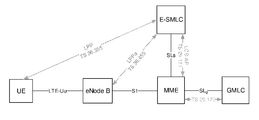
- Positioning in LTE is supported by the architecture illustrated in FIG. 1 , with direct interactions between a User Equipment device (UE) and an Enhanced Serving Mobile Location Center (E-SMLC), which may also be referred to as a location server, are via the LTE Positioning Protocol (LPP). Moreover, there are also interactions between the E-SMLC and an enhanced or evolved Node B (eNB) via the LPP Annex (LPPa) protocol, to some extent supported by interactions between the eNB and the UE via the Radio Resource Control (RRC) protocol.
- UE User Equipment device
- E-SMLC Enhanced Serving Mobile Location Center
- LPPa LPP Annex
- RRC Radio Resource Control
- OTDOA is a UE-assisted method in which the UE measures the Time of Arrival (TOA) of specific Positioning Reference Signals (PRSs) from multiple eNBs and computes the relative differences. These Reference Signal Time Difference (RSTD) measurements are quantized and reported via LPP to the E-SMLC together with an accuracy assessment. Based on known positions of the eNBs and their mutual time synchronization, the E-SMLC estimates the UE position from the RSTD measurements and covariance reports using multilateration. The accuracy depends on the radio conditions of the received signals, the number of received signals, as well as the deployment, which means that it will vary spatially.
- TOA Time of Arrival
- PRSs Positioning Reference Signals
- RSTD Reference Signal Time Difference
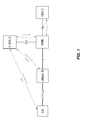
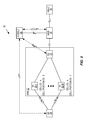
- FIG. 2 illustrates multilateration in OTDOA while considering eNB1 as the reference cell.
- the TOAs from neighboring cells are subtracted from that of the reference cell to provide corresponding RSTD measurements.
- Each such RSTD measurement determines a hyperbola, and the intersecting point of these hyperbolas can be considered as the UE position.
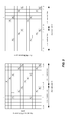
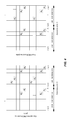
- FIGS. 3 and 4 show the arrangement of the PRSs (i.e., the PRS patterns) in one resource block for normal Cyclic Prefix (CP) and extended CP, respectively.
- CP Cyclic Prefix
- PDSCH Physical Downlink Shared Channel
- the Physical Downlink Control Channel (PDCCH) and CRSs are retained in the subframe, while PRSs are distributed in a “diagonal” way in between CRSs. Similar to CRS, a cell-specific frequency shift (defined as Physical Cell Identity (PCI) modulo 6) is applied to the PRS pattern, which helps avoid time-frequency PRS collision for up to six neighbor cells.
- PCI Physical Cell Identity
- the PRSs are mapped to the resource element (k, l), i.e. the time-frequency PRS pattern can be written as:
- n s is the slot number and N RB PRS , and N RB DL , and N RB max,DL denote the number of Resource Blocks (RBs) for PRS, PDSCH, and downlink maximum bandwidth, respectively;
- consecutive PRS subframes are transmitted periodically in the downlink.
- PRSs are be transmitted in N PRS consecutive downlink subframes, where N PRS is configured by higher layers.
- one positioning occasion may contain up to six consecutive PRS subframes.
- TDD Time Division Duplexing
- uplink subframes and other special frames cannot contain PRSs.
- the PRS periodicity T PRS and subframe offset ⁇ PRS are derived from the PRS configuration index I PRS .
- the PRS configuration index I PRS is configured by higher layers. PRSs are transmitted only in configured downlink subframes. PRSs are not transmitted in Downlink Pilot Time Slots (DwPTSs).
- DwPTSs Downlink Pilot Time Slots
- PRS muting has been introduced to further reduce inter-cell interference by muting PRS transmissions in other cells based on a periodic “muting pattern.”
- the positioning architecture in LTE operates via two positioning protocols: the LPP and the LPPa.
- LPP is used for communication between the E-SMLC and a UE
- LPPa is the communication protocol between an eNB and the E-SMLC.
- the information exchange between an eNB and an E-SMLC may be used for OTDOA positioning to support data collection from eNBs and configurations to eNBs.
- Such configuration information includes PRS configuration index table, number of consecutive PRSs, PRS bandwidth, etc.
- the UE estimates the TOA of a reference cell and other detected cells based on received assistance information from the E-SMLC. Then, the UE computes the RSTD of each detected cell in relation to the reference cell.
- the UE estimates the RSTD measurement quality and reports the uncertainty via a range:
- n is an index to indicate the value range within which the RSTD uncertainty is estimated to be (see 3GPP TS 36.355, Section 6.5.1.5).
- the “E-UTRAN Access Point Position” is associated with PCI, i.e., the locations of TPs sharing the same PCI cannot be differentiated. Hence, they cannot be used for indoor positioning based on OTDOA.
- a method of operation of a TP in a cellular communications network is provided.
- the TP is one of multiple of non-co-located TPs of a shared cell that has a shared cell identifier.
- the method of operation of the TP comprises transmitting a PRS having at least one parameter that is a function of a cell portion identifier of the TP.
- the at least one parameter of the PRS that is a function of the cell portion identifier of the TP comprises a frequency-shift of the PRS, a portion of a system bandwidth in which the PRS is transmitted, and/or a PRS sequence used for the PRS.
- the at least one parameter of the PRS that is a function of the cell portion identifier of the TP comprises the frequency-shift of the PRS.
- the frequency-shift of the PRS is a function of the cell portion identifier of the TP and the shared cell identifier. In some embodiments, the frequency-shift of the PRS is defined as:
- N ID cell is the shared cell identifier
- N ID cellPortion is the cell potion identifier of the TP.
- the at least one parameter of the PRS that is a function of the cell portion identifier of the TP comprises the portion of the system bandwidth in which the PRS is transmitted.
- a mapping between the portion of the system bandwidth in which the PRS is transmitted and the cell portion identifier is predefined. In some other embodiments, a mapping between the portion of the system bandwidth in which the PRS is transmitted and the cell portion identifier is randomly assigned.
- the at least one parameter of the PRS that is a function of the cell portion identifier of the TP comprises the PRS sequence used for the PRS.
- the method of operation of the TP further comprises transmitting a second PRS that is cell specific. Further, in some embodiments, a PRS pattern of the PRS having the at least one parameter that is a function of the cell portion identifier of the TP is different than a PRS pattern of the second PRS. In some embodiments, the PRS pattern of the PRS having the at least one parameter that is a function of the cell portion identifier of the TP is the same as the PRS pattern of the second PRS other than the last two resource element positions of the PRS.
- the PRS having the at least one parameter that is a function of the cell portion identifier of the TP does not overlap, in time, the second PRS that is cell specific.
- each PRS occasion of the PRS having the at least one parameter that is a function of the cell portion identifier of the TP is separated in time from each PRS occasion of the second PRS that is cell specific.
- at least one PRS occasion of the PRS having the at least one parameter that is a function of the cell portion identifier of the TP is adjacent in time to at least one PRS occasion of the second PRS that is cell specific.
- Embodiments of a TP in a cellular network are also disclosed.
- the TP is one of multiple non-co-located TPs of a shared cell that has a shared cell identifier.
- the TP comprises a transmitter operable to transmit, via the transmitter, a PRS having at least one parameter that is a function of a cell portion identifier of the TP.
- the at least one parameter comprises a frequency-shift of the PRS, a portion of a system bandwidth in which the PRS is transmitted, and/or a PRS sequence used for the PRS.
- Embodiments of a base station for operation in a cellular communications network are also disclosed.
- the base station comprises a plurality of non-co-located TPs serving a shared cell having a shared cell identifier. At least some of the non-co-located TPs have different cell portion identifiers.
- the base station further comprises a detection unit communicatively coupled to the non-co-located TPs. The detection unit is operable to, for each TP of the non-co-located TPs, provide, to the TP for transmission, a PRS having at least one parameter that is a function of the cell portion identifier of the TP.
- the at least one parameter comprises a frequency-shift of the PRS, a portion of a system bandwidth in which the PRS is transmitted, and/or a PRS sequence used for the PRS.
- the at least one parameter of the PRS that is a function of the cell portion identifier of the TP comprises the frequency-shift of the PRS.
- the frequency-shift of the PRS is a function of the cell portion identifier of the TP and the shared cell identifier. In some embodiments, the frequency-shift of the PRS is defined as:
- N ID cell is the shared cell identifier
- N ID cellPortion is the cell potion identifier of the TP.
- the at least one parameter of the PRS that is a function of the cell portion identifier of the TP comprises the portion of the system bandwidth in which the PRS is transmitted.
- the at least one parameter of the PRS that is a function of the cell portion identifier of the TP comprises the PRS sequence used for the PRS.
- the detection unit is further operable to provide, to each of the plurality of TPs for transmission, a second PRS that is cell specific. Further, in some embodiments, a PRS pattern of the PRS having the at least one parameter that is a function of the cell portion identifier of the TP is different than a PRS pattern of the second PRS. In some embodiments, the PRS pattern of the PRS having the at least one parameter that is a function of the cell portion identifier of the TP is the same as the PRS pattern of the second PRS other than the last two resource element positions of the PRS.
- the PRS having the at least one parameter that is a function of the cell portion identifier of the TP does not overlap, in time, the second PRS that is cell specific.
- a base station for operation in a cellular communications network has a plurality of non-co-located TPs serving a shared cell having a shared cell identifier. At least some of the plurality of non-co-located TPs have different cell portion identifiers.
- the base station comprises a module operable to, for each TP of the plurality of non-co-located TPs, provide, to the TP for transmission, a PRS having at least one parameter that is a function of a cell portion identifier of the TP.
- the at least one parameter comprising a frequency-shift of the PRS, a portion of a system bandwidth in which the PRS is transmitted, and/or a PRS sequence used for the PRS.
- Embodiments of a method of operation of a wireless device in a cellular communications network are also provided.
- the method of operation of a wireless device comprises receiving assistance information from the cellular communications network, where the assistance information comprises information that enables the wireless device to receive cell portion specific PRSs from a plurality of non-co-located TPs of a shared cell.
- the method further comprises receiving at least one of the cell portion specific PRSs from respective non-co-located TPs of the shared cell and performing Received Signal Time Difference (RSTD) measurements on the at least one of the cell portion identifier specific PRSs.
- RSTD Received Signal Time Difference
- the method further comprises determining a position of the wireless device based on the RSTD measurements on the at least one of the cell portion specific PRSs.
- the method further comprises sending the RSTD measurements on the at least one of the cell portion specific PRSs to a network node of the cellular communications network.
- the assistance information comprises a list of cell portion identifiers corresponding to the cell portion specific PRSs.
- the assistance information comprises physical locations of the non-co-located TPs.
- the assistance information comprises one or more configuration parameters for the cell portion specific PRSs.
- the one or more configuration parameters comprise one or more time-domain parameters for the cell portion specific PRS.
- the one or more time-domain parameters comprise a number, N PRS,cellP , of consecutive downlink subframes on which the cell portion specific PRS is transmitted in a PRS occasion; a subframe offset, ⁇ PRS,cellP , for a first subframe of the number, N PRS,cellP , of consecutive downlink subframes on which the cell portion specific PRS is transmitted in a PRS occasion; a periodicity, T PRS , of the cell portion specific PRS; and/or a muting pattern of the cell portion specific PRS.
- the one or more configuration parameters comprise one or more frequency-domain parameters for the cell portion specific PRS.
- the one or more frequency-domain parameters comprise information that indicates a set of physical resource blocks in the frequency domain in which the cell portion specific PRS is transmitted.
- Embodiments of a wireless device for operation in a cellular communications network comprises a transceiver and at least one processor operable to: receive, via the transceiver, assistance information from the cellular communications network, the assistance information comprising information that enables the wireless device to receive cell portion specific PRSs from a plurality of non-co-located TPs of a shared cell; receive, via the transceiver, at least one of the cell portion specific PRSs from respective non-co-located TPs of the shared cell; and perform RSTD measurements on at least one of the cell portion identifier specific PRSs.
- a wireless device for operation in a cellular communications network comprises means for receiving assistance information from the cellular communications network, the assistance information comprising information that enables the wireless device to receive cell portion PRSs from a plurality of non-co-located TPs of a shared cell; means for receiving at least one of the cell portion specific PRSs from respective non-co-located TPs of the shared cell; and means for performing RSTD measurements on at least one of the cell portion identifier specific PRSs.
- a wireless device for operation in a cellular communications network comprises an assistance information reception module operable to receive assistance information from the cellular communications network, the assistance information comprising information that enables the wireless device to receive cell portion specific PRSs from a plurality of non-co-located TPs of a shared cell; a PRS reception module operable to receive at least one of the cell portion specific PRSs from respective non-co-located TPs of the shared cell; and a measurement module operable to perform RSTD measurements on at least one of the cell portion identifier specific PRSs.
- FIG. 1 illustrates an Long Term Evolution (LTE) architecture supporting positioning
- FIG. 2 illustrates multilateration in accordance with an Observed Time Difference of Arrival (OTDOA) positioning scheme
- FIGS. 3 and 4 illustrate legacy Positioning Reference Signal (PRS) patterns
- FIG. 5 illustrates one example of a cellular communications system in which embodiments of the present disclosure may be implemented
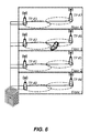
- FIG. 6 illustrates one specific example of the base station of FIG. 5 in a typical indoor or small-cell scenario
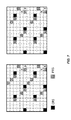
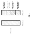
- FIG. 7 illustrates one example of an enhanced or evolved PRS (ePRS) pattern with improved correlation property, where compared to the legacy PRS pattern shown in FIG. 3 , the Resource Elements (REs) in the last two symbols are adjusted such that the REs in the ePRS pattern are distributed more evenly in frequency in accordance with some embodiments of the present disclosure;
- ePRS enhanced or evolved PRS
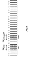
- FIG. 8 illustrates an example in which ePRSs are transmitted in different portions of the system bandwidth as a function of the cell portion identifiers associated with the respective Transmit Points (TPs) in accordance with some embodiments of the present disclosure
- FIG. 9 illustrates an example in which ePRS and PRS occasions do not overlap in time in accordance with some embodiments of the present disclosure
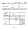
- FIG. 10 illustrates modifications to Information Elements (IEs) used for LTE Positioning Protocol (LPP) signaling in accordance with some embodiments of the present disclosure
- FIG. 11 illustrates a modified OTDOA INFORMATION RESPONSE message utilized for LPP Annex (LPPa) signaling in accordance with some embodiments of the present disclosure
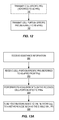
- FIGS. 12 through 14 are flow charts that illustrate the operation of various nodes in the cellular communications system of FIG. 5 in accordance with embodiments of the present disclosure
- FIGS. 15 and 16 illustrate the operation of the cellular communications system of FIG. 5 in accordance with some embodiments of the present disclosure
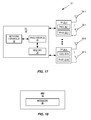
- FIGS. 17 and 18 are block diagrams of the base station of FIG. 5 according to some embodiments of the present disclosure.
- FIGS. 19 and 20 are block diagrams of the Enhanced Serving Mobile Location Center (E-SMLC) of FIG. 5 according to some embodiments of the present disclosure.
- E-SMLC Enhanced Serving Mobile Location Center
- FIGS. 21 and 22 are block diagrams of the UE of FIG. 5 according to some embodiments of the present disclosure.
- Radio Node As used herein, a “radio node” is either a radio access node or a wireless device.
- Radio Access Node is any node in a radio access network of a cellular communications network that operates to wirelessly transmit and/or receive signals.
- a radio access node include, but are not limited to, a base station (e.g., an enhanced or evolved Node B (eNB) in a Third Generation Partnership Project (3GPP) Long Term Evolution (LTE) network), a high-power or macro base station, a low-power base station (e.g., a micro base station, a pico base station, a home eNB, or the like), and a relay node.
- a base station e.g., an enhanced or evolved Node B (eNB) in a Third Generation Partnership Project (3GPP) Long Term Evolution (LTE) network
- 3GPP Third Generation Partnership Project
- LTE Long Term Evolution
- a “wireless device” is any type of device that has access to (i.e., is served by) a cellular communications network by wirelessly transmitting and/or receiving signals to a radio access node(s).
- Some examples of a wireless device include, but are not limited to, a User Equipment device (UE) in a 3GPP LTE network, a Machine Type Communication (MTC) device, and a Narrowband Internet of Things (IoT) device.
- UE User Equipment device
- MTC Machine Type Communication
- IoT Narrowband Internet of Things
- Network Node As used herein, a “network node” is any node that is either part of the radio access network or the core network of a cellular communications network/system.
- a “transmit point” or “TP” is a set of co-located antennas. More specifically, a TP is a device or system that implements a set of co-located antennas. A cell can correspond to one or more TPs. Some example TPs are, but are not limited to, Remote Radio Heads (RRHs) and a set of co-located antenna(s) in a Distributed Antenna System (DAS).
- RRHs Remote Radio Heads
- DAS Distributed Antenna System
- Cell Portion As used herein, a “cell portion” is a geographical part of a cell.
- 3GPP LTE terminology or terminology similar to 3GPP LTE terminology is oftentimes used.
- the concepts disclosed herein are not limited to a 3GPP system.
- a “cell portion” is a geographical part of a cell.
- a cell portion is semi-static, and identical for both the uplink and the downlink.
- a cell portion is uniquely identified by its Cell Portion Identity (ID).
- ID is the unique identifier for a cell portion within a cell.
- Table 9.2.12-1 of 3GPP TS 35.455 V12.2.0 defines Cell Portion ID as follows:
- the eNB shall return the result of the measurement in the Enhanced Cell ID (E-CID) MEASUREMENT INITIATION RESPONSE message including, if available, the Evolved Universal Terrestrial Radio Access Node (E-UTRAN) Access Point Position IE in the E-CID Measurement Result IE, and the Enhanced Serving Mobile Location Center (E-SMLC) shall consider that the E-CID measurements for the UE has been terminated by the eNB.
- E-CID Enhanced Cell ID
- E-UTRAN Evolved Universal Terrestrial Radio Access Node
- E-SMLC Enhanced Serving Mobile Location Center
- the eNB shall include the Cell Portion ID IE in the E-CID MEASUREMENT INITIATION RESPONSE message.
- the E-SMLC may use the value as the cell portion for the measurement.
- a set of geographically collocated antennas that correspond to a particular sectorization are configured as a cell.
- a UE also referred to herein as a terminal
- CoMP Coordinated Multipoint
- phantom cell phantom cell, and other enhancements
- non-co-located antennas are introduced, including distributed antennas, RRHs, etc.
- the antennas configured as a cell may not be geographically co-located.
- the term TP refers to a set of co-located antennas, and a cell can correspond to one or more of such TPs. Note that a single geographical site location may contain multiple TPs in case of sectorization, with one TP corresponding to one sector.
- the UE may be located close to one TP, but far away from another TP, even though the TPs may belong to the same cell.
- PRSs individual positioning signals
- Embodiments of the present disclosure include apparatuses and methods for TPs (e.g., RRHs and/or distributed antennas) in a shared cell (i.e., TPs that share the same cell identity or PCI) to perform Observed Time Difference of Arrival (OTDOA)-based positioning.
- TPs e.g., RRHs and/or distributed antennas
- OTDOA Observed Time Difference of Arrival
- the TPs can be separated geographically such that they can transmit independent PRSs as if they were eNBs.
- different PRS patterns or scheduling shall be used.
- the disclosure also presents how to add signaling information related to the Cell Portion ID to LTE Positioning Protocol (LPP) to enable OTDOA at the TP level.
- LTP LTE Positioning Protocol
- the disclosure also describes the signaling mechanism for enhanced or evolved PRS (ePRS) configurations.
- TPs that share the same PCI can transmit separate PRSs for positioning purposes. Interference between PRSs transmitted from different TPs can be mitigated.
- Embodiments of the present disclosure are implemented in a cellular communications system.
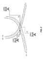
- a cellular communications system 10 is illustrated in FIG. 5 .
- the cellular communications system 10 is an LTE system and, as such, LTE terminology is used. Note, however, that the present disclosure is not limited to LTE; rather, the concepts disclosed herein can be utilized in any cellular communications system that includes multiple non-co-located TPs sharing the same cell ID.
- the cellular communications system 10 includes a cellular network including an eNB 12 , an E-SMLC 14 (which may also be referred to herein as a location server), a Mobility Management Entity (MME) 16 , and a Gateway Mobile Location Centre (GMLC) 18 .
- MME Mobility Management Entity
- GMLC Gateway Mobile Location Centre
- the eNB 12 is part of a radio access network and, as such, may generally be referred to herein as a radio access node.
- the E-SMLC 14 , the MME 16 , and the GMLC 18 are part of a core network and, as such, may generally be referred to herein as core network nodes.
- the eNB 12 includes a number of TPs 20 - 1 through 20 -N connected to a centralized Detection Unit (DU) 22 .
- the TPs 20 - 1 through 20 -N operate according to a shared cell scheme and, as such, share the same cell ID, which in this example is denoted as Cell ID A.
- the TPs 20 - 1 through 20 -N are assigned or otherwise associated with different Cell Portion IDs.
- the TP 20 - 1 is associated with Cell Portion ID X
- the TP 20 -N is associated with Cell Portion ID Y. Note that, in some embodiments, each TP 20 is assigned a different Cell Portion ID.
- some of the TPs 20 may share the same Cell Portion ID (e.g., TPs 20 that are geographically close to one another (e.g., on the same floor of a building) may be associated with the same Cell Portion ID).
- a TP 20 can include an antenna or a set of co-located antennas in a DAS, a RRH, or the like.
- a TP 20 can include a transceiver and an antenna system (e.g., one or more antennas) for transmitting and receiving signals.
- a TP 20 may also include a processor.
- the cellular communications system 10 also includes a UE 24 that transmits and receives wireless signals to and from the cellular network.
- the UE 24 can include a transceiver, a processor, and a memory.
- the transceiver is configured to send and receive wireless signals via an antenna system.
- the processor is configured to execute operations stored in memory.
- FIG. 6 illustrates one specific example of the eNB 12 of FIG. 5 in a typical indoor or small-cell scenario.
- the eNB 12 By enabling the eNB 12 to signal the Cell Portion IDs of the TPs 20 to the E-SMLC 14 , the TPs 20 can be separated geographically from a positioning perspective. For example, the coverage area of a particular TP 20 is associated with one Cell Portion ID.
- an ePRS By associating the Cell Portion ID with its own PRS (referred to herein as an ePRS), the corresponding TP 20 can be separated, for positioning purposes, as if it were an eNB.
- a new PRS transmission can be transmitted simultaneously with the legacy PRS transmission.
- the new PRS is referred to herein as an ePRS.
- antenna ports of a macro eNB transmits legacy PRS, and TPs 20 connected to the same DU 22 transmit new PRSs independently.
- FIG. 6 illustrates an indoor small-cell scenario with multiple TPs 20 on each floor. All TPs 20 may share the same PCI.
- the eNB can signal the Cell Portion ID to the E-SMLC 14 , and therefore the TPs 20 can be separated geographically from a positioning perspective. For example, the coverage area of a TP 20 is associated with one Cell Portion ID. By associating the Cell Portion ID with its own (e)PRS, the corresponding TP 20 can be separated as if it were an eNB.
- a PRS transmission in accordance with embodiments of the present disclosure can be transmitted with the legacy PRS transmission (e.g., simultaneously or substantially simultaneously with the legacy PRS transmission).
- the new PRS can also be labeled as an evolved PRS (called ePRS hereafter).
- ePRS evolved PRS
- antenna ports of a macro eNB transmits legacy PRS
- TPs 20 connected to the same DU 22 transmit new PRSs independently.
- the ePRSs are sent by TPs 20 (such as distributed antennas and/or RRHs).
- TPs 20 such as distributed antennas and/or RRHs.
- AP Antenna Port
- each TP 20 may be associated with a different AP, e.g., TP1 is associated with AP 106 and Cell Portion ID #1, TP2 is associated with AP 206 and Cell Portion ID #2, TP3 is associated with AP 306 and Cell Portion ID #3, etc.
- the PRS patterns transmitted from different TPs 20 have different PRS patterns.
- the new PRS mapping to a Resource Element (RE) can be defined as, for example, described in the following embodiments.
- the existing PRS pattern i.e., the PRS pattern defined in the current LTE specifications
- the frequency shift is defined as a function of Cell Portion ID, N ID cellPortion , and cell ID, N ID cell . That is,
- a new PRS pattern in a Physical Resource Block can be defined for ePRS.
- PRB Physical Resource Block
- FIG. 7 illustrates the new PRS patterns (with normal Cyclic Prefix (CP)) for one/two Physical Broadcast Channel (PBCH) ports and four PBCH ports.
- CP Cyclic Prefix
- PBCH Physical Broadcast Channel
- different TPs 20 may use ePRS with certain different parameters, such as (a) different frequency shift in terms of RE mapping within a PRB, (b) different PRS sequences, etc.
- the set of PRBs that AP 106 uses to send ePRS is different from the set of PRBs that AP 6 uses to send PRS.
- TPs 20 of different Cell Portion IDs can occupy non-overlapping portions of the bandwidth (i.e., the system bandwidth) in the same subframe, so that several TPs 20 can transmit ePRS simultaneously.
- TPs 20 associated with Cell Portion ID ⁇ 1, 2, 3, 4 ⁇ are scheduled to send ePRS in the same subframe(s).
- the system bandwidth is 20 megahertz (MHz) (or 100 PRBs).
- ePRS is transmitted in N PRS,cellP consecutive downlink subframes, where N PRS,cellP is configured by higher layers.
- the group of ePRSs should be scheduled in a way such that it does not overlap with the legacy PRS transmission.
- FIG. 9 One such example is shown in FIG. 9 , where the ePRS occasion and the PRS occasion are separated in time. However, in some other embodiments, the ePRS occasion and the PRS occasion are adjacent in time such that, together, the ePRS occasion and the PRS occasion form a continuous ePRS/PRS occasion in time.
- the PRS instances, for the first subframe of the N PRS,cellP downlink subframes, satisfies:
- the periodicity of the ePRS can be configured to be the same as T PRS of the PRS of the same cell, in general, the ePRS can be configured with its own periodicity T ePRS .
- Other parameters of ePRS can be configured individually as well, such as its muting pattern.
- the location server (the E-SMLC 14 or a Secure User Plane Location Platform (SLP)) can send the assistance information to the UE 24 to utilize ePRS and Cell Portion information, in addition to existing PRS information.
- the UE 24 reports the additional Reference Signal Time Difference (RSTD) measurements corresponding to the Cell Portions to the E-SMLC 14 through LPP.
- RSTD Reference Signal Time Difference
- OTDOA positioning is carried out based on the data of a group of TP locations, RSTD measurements, and Cell Portion IDs.
- the following parameters are added to LPP signaling sent to the UE 24 for ePRS configuration:
- the LPP protocol is modified to enable ePRS-based positioning.
- the Cell Portion and ePRS information is added to in the field of “OTDOA-ReferenceCellInfo.”
- the IE OTDOA-ReferenceCellInfo is used by the location server (e.g., the E-SMLC 14 ) to provide assistance data reference cell information for OTDOA assistance data.
- a new IE “eprs-info” can be defined and included in the OTDOA Assistance Data Elements in 3GPP TS 36.455 V12.2.0.
- the modifications can be as illustrated in FIG. 10 .
- the LPPa protocol is also modified to enable ePRS-based positioning.
- the “OTDOA INFORMATION RESPONSE” message can be enhanced to include cell portion information.
- the OTDOA INFORMATION RESPONSE is a message is sent by the eNB 12 to the E-SMLC 14 to provide OTDOA information.
- the modified OTDOA INFORMATION RESPONSE is illustrated in FIG. 11 .
- the IE “OTDOA Cell Portion Information” contains OTDOA information of a cell portion.
- FIGS. 12 through 14 are flow charts that illustrate the operation of various nodes in the cellular communications system 10 of FIG. 5 in accordance with embodiments described above.
- FIG. 12 is a flow chart that illustrates the operation of one of the TPs 20 in accordance with embodiments of the present disclosure. This process is equally applicable to the other TPs 20 .
- the TP 20 transmits a cell-specific PRS (referred to herein simply as a PRS) (step 100 ).
- This cell-specific PRS is, for example, the legacy PRS transmitted in a LTE network.
- the same cell-specific PRS is also transmitted by each of the other TPs 20 in the shared cell (i.e., having the same PCI).
- the TP 20 also transmits a cell-portion-specific PRS (referred to herein as an ePRS), as described above (step 102 ).
- ePRS a cell-portion-specific PRS
- one or more parameters of the ePRS are a function of a cell portion ID of the TP 20 .
- the one or more parameters of the ePRS that are a function of the cell portion ID may include, as described above, a frequency shift of the ePRS, a portion of a system bandwidth in which the ePRS is transmitted, and/or a PRS sequence used for the ePRS.
- the ePRS may use a new PRS pattern (i.e., one that is different than the PRS pattern used for the PRS of step 100 ).
- the timing of the ePRS may be such that it does not overlap, in time, the PRS, as described above.
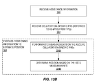
- FIGS. 13A and 13B are flow charts that illustrate the operation of the UE 24 according to some embodiments of the present disclosure.
- the UE 24 sends RSTD measurements to the E-SMLC 14 for position determination.
- the UE 24 uses its own RSTD measurements to determine its own position.
- the UE 24 receives assistance information that enables the UE 24 to perform RSTD measurements on the cell-portion-specific PRSs (ePRSs) transmitted by the TPs 20 in a shared cell (step 200 ).
- this assistance information is received by the UE 24 from the E-SMLC 14 via LPP.
- the assistance information includes:
- the UE 24 receives the cell-portion-specific PRSs (ePRSs) from one or more of the TPs 20 , depending on the position of the UE 24 (step 202 ).
- the UE 24 may also receive one or more PRSs from one or more other cells (e.g., from neighboring cells) and/or one or more ePRSs from one or more cell portions of one or more other cells (e.g., one or more cell portions of one or more neighboring cells).
- the UE 24 performs RSTD measurements on the received cell-portion-specific PRSs (ePRSs) (step 204 ).
- the UE 24 may also perform RSTD measurements on one or more other cell-specific PRSs and/or one or more other ePRSs of cell portions of one or more other cells.
- the UE 24 sends the RSTD measurements to the network (e.g., to a network node such as the E-SMLC 14 via LPP) (step 206 ).
- the network node determines the position of the UE 24 based on the RSTD measurements and known positions of the TPs 20 assigned to the respective cell portions (and optionally known positions of the radio access nodes originating any other the cell-specific PRSs or cell-portion-specific ePRSs received and measured by the UE 24 ).
- FIG. 13B The embodiment of FIG. 13B is similar to that of FIG. 13A , but where the UE 24 determines the position of the UE 24 .
- the UE 24 receives assistance information that enables the UE 24 to perform RSTD measurements on the cell-portion-specific PRSs (ePRSs) transmitted by the TPs 20 in a shared cell (step 300 ).
- this assistance information is received by the UE 24 from the E-SMLC 14 via LPP.
- the assistance information includes:
- the UE 24 uses the assistance information to receive the cell-portion-specific PRSs (ePRSs) from one or more of the TPs 20 , depending on the position of the UE 24 (step 302 ).
- the UE 24 may also receive one or more PRSs from one or more other cells (e.g., from neighboring cells) and/or one or more ePRSs from one or more cell portions of one or more other cells (e.g., one or more cell portions of one or more neighboring cells).
- the UE 24 estimates its position (step 304 ).
- the UE 24 performs RSTD measurements on the received cell-portion-specific PRSs (ePRSs) (step 304 A).
- the UE 24 may also perform RSTD measurements on one or more other cell-specific PRSs and/or one or more other ePRSs of cell portions of one or more other cells.
- the UE 24 determines the position of the UE 24 based on the RSTD measurements and the known positions of the respective TPs 20 (and optionally known positions of the radio access nodes originating any other the cell-specific PRSs or cell-portion-specific ePRSs received and measured by the UE 24 ) using, e.g., a known multilateration technique (step 304 B).
- multilateration requires RSTD measurements from multiple TPs and/or base stations, where these multiple TPs and/or base stations include at least one of the TPs 20 in the shared cell.
- multilateration may be performed based only on RSTD measurements received for multiple TPs (e.g., at least two of the TPs 20 or preferably at least three of the TPs 20 ) in the shared cell.
- multilateration may be performed based on RSTD measurement(s) from a TP(s) 20 in the shared cell and one or more RSTD measurements for, e.g., a base station(s) of a neighboring cell(s) and/or TP(s) 20 in respective cell portions of one or more neighboring cells.
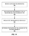
- FIG. 14 is a flow chart that illustrates the operation of the E-SMLC 14 according to some embodiments of the present disclosure.
- the E-SMLC 14 receives configuration information from the eNB 12 , as described above (step 400 ). This configuration is received via LPPa.
- the configuration information includes:
- the E-SMLC 14 receives, from the UE 24 , RSTD measurements for one or more of the cell portions (i.e., for the cell-portion-specific PRS (ePRS) received by the UE 24 from one or more of the TPs 20 ) (step 404 ).
- the E-SMLC 14 additionally receives, from the UE 24 , RSTD measurements for one or more other cells and/or one or more cell portions of one or more other cells.
- the RSTD measurements may be received from the UE 24 via the LPP.
- the E-SMLC 14 optionally determines the position of the UE 24 based on the received RSTD measurements from the UE 24 and the known positions of the TPs 20 associated with the respective cell portions (and optionally known positions of the radio access nodes originating any other the cell-specific PRSs or cell-portion-specific ePRSs received and measured by the UE 24 ) (step 406 ).
- the E-SMLC 14 may then utilize the position of the UE 24 in any desired manner (e.g., provide the position to the UE 24 for use by the UE 24 , provide the position to another network node, e.g., for use by that other network node, provide the position of the UE 24 to some third-party service such as, e.g., an emergency service or a position-based advertisement service, or the like).
- a third-party service such as, e.g., an emergency service or a position-based advertisement service, or the like.
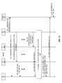
- FIGS. 15 and 16 illustrate the operation of the cellular communications system 10 of FIG. 5 in accordance with embodiments of the present disclosure described above.
- FIG. 15 illustrates an embodiment in which the position of the UE 24 is determined by the E-SMLC 14 based on RSTD measurements received from the UE 24 .
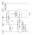
- FIG. 16 illustrates an embodiment in which the UE 24 determines its own position based on RSTD measurements performed by the UE 24 and known positions of the respective TPs 20 .
- the DU 22 i.e., the eNB 12
- the E-SMLC 14 sends configuration information to the E-SMLC 14 via LPPa, as described above (step 500 ).
- the E-SMLC 14 sends assistance information to the UE 24 via LPP as described above (step 502 ).
- the E-SMLC 14 may send the assistance information when, for example, the E-SMLC 14 desires to know the position of the UE 24 .
- the DU 22 sends a Baseband (BB) representation of the ePRS for cell portion ID X to the TP 20 - 1 assigned to cell portion X (step 504 ).
- the TP 20 - 1 receives the BB representation of the ePRS for cell portion ID X and processes (e.g., upconversion, Digital-to-Analog (D/A) conversion, amplification, etc.) the BB representation of the ePRS for cell portion ID X to transmit the ePRS for cell portion ID X (step 506 ).
- the other TPs 20 transmit ePRSs for the respective cell portions.
- the DU 22 sends a BB representation of the ePRS for cell portion ID Y to the TP 20 -N assigned to cell portion Y (step 508 ).
- the TP 20 -N receives the BB representation of the ePRS for cell portion ID Y and processes (e.g., upconversion, D/A conversion, amplification, etc.) the BB representation of the ePRS for cell portion ID Y to transmit the ePRS for cell portion ID Y (step 510 ).
- the TPs 20 - 1 through 20 -N transmit the cell-specific PRSs (step 512 ).
- the UE 24 receives at least some of the ePRSs (i.e., one or more of the ePRSs) transmitted by the TPs 20 - 1 through 20 -N and performs RSTD measurements on the received ePRSs (step 514 ).
- the UE 24 may also receive PRS(s) from another cell(s) and/or ePRS(s) from a cell portion(s) of another cell(s) and perform RSTD measurements on those (e)PRS(s).
- the UE 24 sends the RSTD measurements to the E-SMLC 14 via LPP (step 516 ).
- the E-SMLC 14 determines the position of the UE 24 based on the RSTD measurements (step 518 ).
- FIG. 16 illustrates an embodiment that is substantially the same as that of FIG. 15 but where the UE 24 determines its own position.
- the DU 22 i.e., the eNB 12
- the E-SMLC 14 sends configuration information to the E-SMLC 14 via LPPa, as described above (step 600 ).
- the E-SMLC 14 sends assistance information to the UE 24 via LPP as described above (step 602 ).
- the assistance information includes the positions of the TPs 20 .
- the positions of the TPs 20 may be provided to the UE 24 by a mechanism other than the assistance information (e.g., in some other form of signaling between the UE 24 and the network).
- the E-SMLC 14 may send the assistance information when, for example, the E-SMLC 14 desires to know the position of the UE 24 .
- the DU 22 sends a BB representation of the ePRS for cell portion ID X to the TP 20 - 1 assigned to cell portion X (step 604 ).
- the TP 20 - 1 receives the BB representation of the ePRS for cell portion ID X and processes (e.g., upconversion, D/A conversion, amplification, etc.) the BB representation of the ePRS for cell portion ID X to transmit the ePRS for cell portion ID X (step 606 ).
- the other TPs 20 transmit ePRSs for the respective cell portions.
- the DU 22 sends a BB representation of the ePRS for cell portion ID Y to the TP 20 -N assigned to cell portion Y (step 608 ).
- the TP 20 -N receives the BB representation of the ePRS for cell portion ID Y and processes (e.g., upconversion, D/A conversion, amplification, etc.) the BB representation of the ePRS for cell portion ID Y to transmit the ePRS for cell portion ID Y (step 610 ).
- the TPs 20 - 1 through 20 -N transmit the cell-specific PRSs (step 612 ).
- the UE 24 receives at least some of the ePRSs (i.e., one or more of the ePRSs) transmitted by the TPs 20 - 1 through 20 -N and performs RSTD measurements on the received ePRSs (step 614 ).
- the UE 24 may also receive PRS(s) from another cell(s) and/or ePRS(s) from a cell portion(s) of another cell(s) and perform RSTD measurements on those (e)PRS(s).
- the UE 24 determines the position of the UE 24 based on the RSTD measurements and the known positions of the TPs 20 of the respective cell portions (and, optionally, known positions of the radio access nodes of any other measured (e)PRS(s)) (step 616 ).
- FIGS. 17 and 18 are block diagrams of the eNB 12 of FIG. 5 according to some embodiments of the present disclosure.
- the eNB 12 includes the DU 22 and the TPs 20 - 1 through 20 -N.
- the DU 22 includes one or more processors 25 (e.g., one or more Central Processing Units (CPUs), one or more Application Specific Integrated Circuits (ASICs), one or more Field Programmable Gate Arrays (FPGAs), and/or the like), memory 26 , and a network interface 28 .
- processors 25 e.g., one or more Central Processing Units (CPUs), one or more Application Specific Integrated Circuits (ASICs), one or more Field Programmable Gate Arrays (FPGAs), and/or the like
- memory 26 e.g., one or more Central Processing Units (CPUs), one or more Application Specific Integrated Circuits (ASICs), one or more Field Programmable Gate Arrays (FPGAs), and/or the like
- memory 26 e
- the TPs 20 - 1 through 20 -N which are non-co-located, include respective transmitters 30 - 1 through 30 -N and receivers 32 - 1 through 32 -N coupled to respective antennas 34 - 1 through 34 -N. While not illustrated, the TPs 20 may additionally include one or more processors and potentially memory, depending on the particular implementation.
- the network interface 28 enables the eNB 12 to communicate with other network nodes (e.g., the E-SMLC 14 ).
- the functionality of the eNB 12 described above is fully or partially implemented in software that is stored, e.g., in the memory 26 and executed by the processor(s) 25 . Further, the functionality of the TPs 20 described above may be implemented in hardware (e.g., the transmitters 30 ) or in a combination of hardware and software (e.g., processor(s) executing software instructions in addition to the transmitters 30 ).
- a computer program including instructions which, when executed by at least one processor, causes the at least one processor to carry out the functionality of the eNB 12 according to any of the embodiments described herein is provided.
- a carrier containing the aforementioned computer program product is provided.
- the carrier is one of an electronic signal, an optical signal, a radio signal, or a computer readable storage medium (e.g., a non-transitory computer readable medium such as the memory 26 ).
- FIG. 18 is a block diagram of the eNB 12 according to some other embodiments of the present disclosure.
- the eNB 12 includes one or more modules 36 , each of which is implemented in software.
- the module(s) 36 may include, for example, a configuration module that operates to send configuration information to the E-SMLC 14 , as described above, via, e.g., a network interface of the eNB 12 (not shown in FIG. 18 ).
- the module(s) 36 may also include an ePRS transmission module(s) that operate to transmit ePRSs via the TPs 20 , as described above.
- FIGS. 19 and 20 are block diagrams of the E-SMLC 14 according to some embodiments of the present disclosure.
- the E-SMLC 14 includes one or more processors 38 (e.g., one or more CPUs, one or more ASICs, one or more FPGAs, and/or the like), memory 40 , and a network interface 42 .
- processors 38 e.g., one or more CPUs, one or more ASICs, one or more FPGAs, and/or the like
- memory 40 e.g., one or more RAMs, a processors 38 , and/or the like
- the functionality of the E-SMLC 14 described herein is implemented in software that is stored e.g., in the memory 40 and executed by the processor(s) 38 .
- a computer program including instructions which, when executed by at least one processor, causes the at least one processor to carry out the functionality of the E-SMLC 14 according to any of the embodiments described herein is provided.
- a carrier containing the aforementioned computer program product is provided.
- the carrier is one of an electronic signal, an optical signal, a radio signal, or a computer readable storage medium (e.g., a non-transitory computer readable medium such as the memory 40 ).
- FIG. 20 is a block diagram of the E-SMLC 14 according to some other embodiments of the present disclosure.
- the E-SMLC 14 includes one or more modules 44 , each of which is implemented in software.
- the module(s) 44 may include, for example, a configuration information reception module that operates to receive configuration information from the eNB 12 (via an associated network interface of the E-SMLC 14 , which is not shown), as described above.
- the module(s) 44 may also include, for example, an assistance information transmission module that operates to send assistance information to the UE 24 (via an associated network interface of the E-SMLC 14 , which is not shown), as described above.
- the module(s) 44 may also include, for example, a position determination module that operates to determine the position of the UE 24 based on RSTD measurements received from the UE 24 and known positions of the TPs 20 , as described above.
- FIGS. 21 and 22 are block diagrams of the UE 24 according to some embodiments of the present disclosure.
- the UE 24 includes one or more processors 46 (e.g., one or more CPUs, one or more ASICs, one or more FPGAs, and/or the like), memory 48 , and one or more transceivers 50 including one or more transmitters 52 and one or more receivers 54 coupled to one or more antennas 56 .
- some or all of the functionality described above as being provided by UEs, Device-to-Device (D2D) devices, MTC or Machine-to-Machine (M2M) devices, and/or any other types of wireless communication devices may be provided by the device processor executing instructions stored on a computer-readable medium, such as the memory 48 shown in FIG. 21 .
- Alternative embodiments of the wireless communication device may include additional components beyond those shown in FIG. 21 that may be responsible for providing certain aspects of the device's functionality, including any of the functionality described above and/or any functionality necessary to support the solution described above.
- a computer program including instructions which, when executed by at least one processor, causes the at least one processor to carry out the functionality of the UE 24 according to any of the embodiments described herein is provided.
- a carrier containing the aforementioned computer program product is provided.
- the carrier is one of an electronic signal, an optical signal, a radio signal, or a computer readable storage medium (e.g., a non-transitory computer readable medium such as the memory 48 ).
- FIG. 22 is a block diagram of the UE 24 according to some other embodiments of the present disclosure.
- the UE 24 includes one or more modules 58 , each of which is implemented in software.
- the module(s) 58 may include, for example, an assistance information reception module that operates to receive (via an associated receiver(s) of the UE 24 , which are not shown) assistance information from the network (e.g., the E-SMLC 14 ), as described above.
- the module(s) 58 may also include, for example, an ePRS reception module and an RSTD measurement module that operate to receive (via an associated receiver(s) of the UE 24 , which are not shown) ePRSs and perform RSTD measurements, as described above.
- the module(s) 58 include a reporting module that operates to send the RSTD measurements to the network (e.g., to the E-SMLC 14 ) (via an associated transmitter(s) of the UE 24 , which are not shown).
- the UE 24 includes a position determination module that operates to determine the position of the UE 24 based on the RSTD measurements, as described above.
- aspects of the embodiments include a method performed at a TP, the TP comprising a transceiver and a hardware processor, the method including transmitting a first positioning reference signal; and transmitting a second positioning reference signal, the second positioning reference signal including a cell portion identifier associated with the TP (i.e., the second positioning reference signal can be differentiated from the first positioning reference signal as a result of different cell portion identifiers).
- aspects of the embodiments are directed to a TP that includes a transceiver and a hardware processor, the TP configured to transmit a first positioning reference signal; and transmit a second positioning reference signal, the second positioning reference signal including a cell portion identifier associated with the TP (i.e., the second positioning reference signal can be differentiated from the first positioning reference signal as a result of different cell portion identifiers).
- aspects of the embodiments are directed to an apparatus adapted to transmit a first positioning reference signal; and transmit a second positioning reference signal, the second positioning reference signal including a cell portion identifier associated with the TP (i.e., the second positioning reference signal can be differentiated from the first positioning reference signal as a result of different cell portion identifiers).
- aspects of the embodiments are directed to an apparatus comprising means adapted to transmit a first positioning reference signal; and transmit a second positioning reference signal, the second positioning reference signal including a cell portion identifier associated with the TP (i.e., the second positioning reference signal can be differentiated from the first positioning reference signal as a result of different cell portion identifiers).
- aspects of the embodiments are directed to an apparatus including means for transmitting a first positioning reference signal; and means for transmitting a second positioning reference signal, the second positioning reference signal including a cell portion identifier associated with the TP (i.e., the second positioning reference signal can be differentiated from the first positioning reference signal as a result of different cell portion identifiers).
- aspects of the embodiments are directed to an apparatus comprising a first module configured to transmit a first positioning reference signal; and a second module configured to transmit a second positioning reference signal, the second positioning reference signal including a cell portion identifier associated with the TP (i.e., the second positioning reference signal can be differentiated from the first positioning reference signal as a result of different cell portion identifiers).
- aspects of the embodiments are directed to a computer program, comprising instructions which, when executed on at least one processor, cause the at least one processor to transmit a first positioning reference signal; and transmit a second positioning reference signal, the second positioning reference signal including a cell portion identifier associated with the TP (i.e., the second positioning reference signal can be differentiated from the first positioning reference signal as a result of different cell portion identifiers).
- a carrier containing the computer program of the previous claim can include an electronic signal, optical signal, radio signal, or computer readable storage medium.
- aspects of the embodiments are directed to a UE that includes a processor, memory, and transceiver.
- the UE is configured to receive cell portion identification information from a TP.
- the UE is configured to receive, from a location server, assistance information.
- the assistance information can include information that allows the UE to use the cell portion information.
- the UE can use the positioning information and assistance information to estimate position (e.g., indoors).
Landscapes
- Engineering & Computer Science (AREA)
- Signal Processing (AREA)
- Computer Networks & Wireless Communication (AREA)
- Physics & Mathematics (AREA)
- General Physics & Mathematics (AREA)
- Radar, Positioning & Navigation (AREA)
- Remote Sensing (AREA)
- Mobile Radio Communication Systems (AREA)
Abstract
Description
- This application claims the benefit of provisional patent application Ser. No. 62/144,141, filed Apr. 7, 2015, the disclosure of which is hereby incorporated herein by reference in its entirety.
- The present disclosure relates to the transmission of Positioning Reference Signals (PRSs) in a cellular communications network.
- Location-based services and emergency call positioning drive the development of positioning in wireless networks. Positioning support in Third Generation Partnership Project (3GPP) Long Term Evolution (LTE) was introduced in
Release 9. This enables operators to retrieve position information for location-based services and to meet regulatory emergency call positioning requirements. Global Positioning System (GPS)-enabled terminals can meet the requirement for positioning, but they cannot provide the required availability due to the satellite signals being blocked in urban and indoor environments. Therefore, other techniques are needed in such environments. - Positioning in LTE is supported by the architecture illustrated in
FIG. 1 , with direct interactions between a User Equipment device (UE) and an Enhanced Serving Mobile Location Center (E-SMLC), which may also be referred to as a location server, are via the LTE Positioning Protocol (LPP). Moreover, there are also interactions between the E-SMLC and an enhanced or evolved Node B (eNB) via the LPP Annex (LPPa) protocol, to some extent supported by interactions between the eNB and the UE via the Radio Resource Control (RRC) protocol. - The following positioning techniques are considered in LTE (see, for example, 3GPP Technical Specification (TS) 36.305 v12.0.0):
-
- Enhanced Cell Identifier/Identity (ID). Essentially, cell ID information associates the UE to the serving area of a serving cell, and then additional information determines a finer granularity position.
- Assisted Global Navigation Satellite System (GNSS). GNSS information retrieved by the UE is supported by assistance information provided to the UE from the E-SMLC.
- Observed Time Difference of Arrival (OTDOA). The UE estimates the time difference of reference signals from different base stations and sends this information to the E-SMLC for multilateration.
- Uplink Time Difference of Arrival (UTDOA): The UE is requested to transmit a specific waveform that is detected by multiple location measurement units (e.g., an eNB) at known positions. These measurements are forwarded to the E-SMLC for multilateration.
- OTDOA is a UE-assisted method in which the UE measures the Time of Arrival (TOA) of specific Positioning Reference Signals (PRSs) from multiple eNBs and computes the relative differences. These Reference Signal Time Difference (RSTD) measurements are quantized and reported via LPP to the E-SMLC together with an accuracy assessment. Based on known positions of the eNBs and their mutual time synchronization, the E-SMLC estimates the UE position from the RSTD measurements and covariance reports using multilateration. The accuracy depends on the radio conditions of the received signals, the number of received signals, as well as the deployment, which means that it will vary spatially.
-
FIG. 2 illustrates multilateration in OTDOA while considering eNB1 as the reference cell. The TOAs from neighboring cells are subtracted from that of the reference cell to provide corresponding RSTD measurements. Each such RSTD measurement determines a hyperbola, and the intersecting point of these hyperbolas can be considered as the UE position. - In principle, it is possible to measure RSTD on any downlink signals e.g., Cell-Specific Reference Signals (CRSs). However, in OTDOA, the UE is required to detect multiple neighboring cell signals, but these signals suffer from poor hearability. Hence, PRSs have been introduced to improve OTDOA positioning performance.
FIGS. 3 and 4 show the arrangement of the PRSs (i.e., the PRS patterns) in one resource block for normal Cyclic Prefix (CP) and extended CP, respectively. In such a PRS subframe, in order to reduce the interference with neighboring cells, no Physical Downlink Shared Channel (PDSCH) data is transmitted. The Physical Downlink Control Channel (PDCCH) and CRSs are retained in the subframe, while PRSs are distributed in a “diagonal” way in between CRSs. Similar to CRS, a cell-specific frequency shift (defined as Physical Cell Identity (PCI) modulo 6) is applied to the PRS pattern, which helps avoid time-frequency PRS collision for up to six neighbor cells. Mathematically, according to 3GPP TS 36.211 V13.0.0, the PRSs are mapped to the resource element (k, l), i.e. the time-frequency PRS pattern can be written as: - for normal CP:
-
- where ns is the slot number and NRB PRS, and NRB DL, and NRB max,DL denote the number of Resource Blocks (RBs) for PRS, PDSCH, and downlink maximum bandwidth, respectively; and
- for extended CP:
-
- The bandwidth for PRB PRS, is configured by higher layers and the cell-specific frequency shift is given by vshift=NID cell mod 6.
- In an LTE system, consecutive PRS subframes (a.k.a. positioning occasions) are transmitted periodically in the downlink. In other words, PRSs are be transmitted in NPRS consecutive downlink subframes, where NPRS is configured by higher layers. According to the LTE specifications, one positioning occasion may contain up to six consecutive PRS subframes. The period of one positioning occasion can be configured to every TPRS=160, 320, 640, and 1280 milliseconds (ms). It is noted that, in Time Division Duplexing (TDD) mode, uplink subframes and other special frames cannot contain PRSs. Another parameter to characterize the PRS transmission schedule is the cell-specific subframe offset, which defines the starting subframe of PRS transmission relative to System Frame Number (SFN)=0. As shown in Table 1 below (which is reproduced from 3GPP TS 36.211), the PRS periodicity TPRS and subframe offset ΔPRS are derived from the PRS configuration index IPRS. The PRS configuration index IPRS is configured by higher layers. PRSs are transmitted only in configured downlink subframes. PRSs are not transmitted in Downlink Pilot Time Slots (DwPTSs). The PRS instances, for the first subframe of the NPRS downlink subframes, must satisfy (10× nf+└ns/2┘−ΔPRS)modTPRS=0.
-
TABLE 1 Positioning reference signal subframe configuration PRS periodicity PRS subframe offset PRS configuration Index TPRS ΔPRS IPRS (subframes) (subframes) 0-159 160 IPRS 160-479 320 IPRS − 160 480-1119 640 IPRS − 480 1120-2399 1280 IPRS − 1120 2400-4095 Reserved - In some cases, in particular in a dense deployment, using only a cell-specific frequency shift may not be sufficient to avoid interference from neighboring cells. Therefore, PRS muting has been introduced to further reduce inter-cell interference by muting PRS transmissions in other cells based on a periodic “muting pattern.”
- The positioning architecture in LTE operates via two positioning protocols: the LPP and the LPPa. LPP is used for communication between the E-SMLC and a UE, while LPPa is the communication protocol between an eNB and the E-SMLC. The information exchange between an eNB and an E-SMLC, as specified in 3GPP TS 36.455 V13.0.0, may be used for OTDOA positioning to support data collection from eNBs and configurations to eNBs. Such configuration information includes PRS configuration index table, number of consecutive PRSs, PRS bandwidth, etc.
- In regard to RSTD reporting, the UE estimates the TOA of a reference cell and other detected cells based on received assistance information from the E-SMLC. Then, the UE computes the RSTD of each detected cell in relation to the reference cell. The RSTD measurements are subject to a quantization with a resolution of 1 Ts for RSTD measurement within ±4096 Ts, and 5 Ts otherwise (1 Ts=1/(15000×2048) seconds is the LTE basic time unit) (see 3GPP TS 36.133, Section 9.1.10.3).
- In addition, the UE estimates the RSTD measurement quality and reports the uncertainty via a range:
-
[nR,(n+1)R−1], - where the reporting resolution is R={5, 10, 20, 30} meters, and n is an index to indicate the value range within which the RSTD uncertainty is estimated to be (see 3GPP TS 36.355, Section 6.5.1.5).
- Current PRS introduced in
LTE Release 9 was designed for macro base stations to support mainly outdoor positioning. As one type of reference signal, the generation of PRSs is associated with PCI and, therefore, PCI is the label to differentiate the PRSs from neighboring cells. Ongoing enhancements to the United States (US) Federal Communication Commission (FCC) Enhanced 911 capability are focusing on in-building positioning. For indoor small-cell scenarios, low-power Remote Radio Heads (RRHs) or distributed antennas are popularly deployed to enhance the spectral efficiency. However, those Transmit Points (TPs) belonging to the same eNB share the same PCI. As defined in 3GPP TS 36.455 V12.2.0, the “E-UTRAN Access Point Position” is associated with PCI, i.e., the locations of TPs sharing the same PCI cannot be differentiated. Hence, they cannot be used for indoor positioning based on OTDOA. - Systems and methods are disclosed herein that relate wireless device positioning based on cell portion specific Positioning Reference Signals (PRSs) by multiple Transmit Points (TPs) in a shared cell. In some embodiments, a method of operation of a TP in a cellular communications network is provided. The TP is one of multiple of non-co-located TPs of a shared cell that has a shared cell identifier. The method of operation of the TP comprises transmitting a PRS having at least one parameter that is a function of a cell portion identifier of the TP. The at least one parameter of the PRS that is a function of the cell portion identifier of the TP comprises a frequency-shift of the PRS, a portion of a system bandwidth in which the PRS is transmitted, and/or a PRS sequence used for the PRS. By transmitting cell-portion-specific PRSs, the TPs in the shared cell enable wireless device positioning based on PRSs transmitted by the non-co-located TPs in the shared cell.
- In some embodiments, the at least one parameter of the PRS that is a function of the cell portion identifier of the TP comprises the frequency-shift of the PRS. Further, in some embodiments, the frequency-shift of the PRS is a function of the cell portion identifier of the TP and the shared cell identifier. In some embodiments, the frequency-shift of the PRS is defined as:
-
v shift=(N ID cell +N ID cellPortion)mod 6 - where vshift is the frequency-shift of the PRS, NID cell is the shared cell identifier, and NID cellPortion is the cell potion identifier of the TP.
- In some embodiments, the at least one parameter of the PRS that is a function of the cell portion identifier of the TP comprises the portion of the system bandwidth in which the PRS is transmitted. In some embodiments, a mapping between the portion of the system bandwidth in which the PRS is transmitted and the cell portion identifier is predefined. In some other embodiments, a mapping between the portion of the system bandwidth in which the PRS is transmitted and the cell portion identifier is randomly assigned.
- In some embodiments, the at least one parameter of the PRS that is a function of the cell portion identifier of the TP comprises the PRS sequence used for the PRS.
- In some embodiments, the method of operation of the TP further comprises transmitting a second PRS that is cell specific. Further, in some embodiments, a PRS pattern of the PRS having the at least one parameter that is a function of the cell portion identifier of the TP is different than a PRS pattern of the second PRS. In some embodiments, the PRS pattern of the PRS having the at least one parameter that is a function of the cell portion identifier of the TP is the same as the PRS pattern of the second PRS other than the last two resource element positions of the PRS.
- In some embodiments, the PRS having the at least one parameter that is a function of the cell portion identifier of the TP does not overlap, in time, the second PRS that is cell specific. In some embodiments, each PRS occasion of the PRS having the at least one parameter that is a function of the cell portion identifier of the TP is separated in time from each PRS occasion of the second PRS that is cell specific. In other embodiments, at least one PRS occasion of the PRS having the at least one parameter that is a function of the cell portion identifier of the TP is adjacent in time to at least one PRS occasion of the second PRS that is cell specific.
- Embodiments of a TP in a cellular network are also disclosed. The TP is one of multiple non-co-located TPs of a shared cell that has a shared cell identifier. The TP comprises a transmitter operable to transmit, via the transmitter, a PRS having at least one parameter that is a function of a cell portion identifier of the TP. The at least one parameter comprises a frequency-shift of the PRS, a portion of a system bandwidth in which the PRS is transmitted, and/or a PRS sequence used for the PRS.
- Embodiments of a base station for operation in a cellular communications network are also disclosed. In some embodiments, the base station comprises a plurality of non-co-located TPs serving a shared cell having a shared cell identifier. At least some of the non-co-located TPs have different cell portion identifiers. The base station further comprises a detection unit communicatively coupled to the non-co-located TPs. The detection unit is operable to, for each TP of the non-co-located TPs, provide, to the TP for transmission, a PRS having at least one parameter that is a function of the cell portion identifier of the TP. The at least one parameter comprises a frequency-shift of the PRS, a portion of a system bandwidth in which the PRS is transmitted, and/or a PRS sequence used for the PRS.
- In some embodiments, the at least one parameter of the PRS that is a function of the cell portion identifier of the TP comprises the frequency-shift of the PRS. In some embodiments, the frequency-shift of the PRS is a function of the cell portion identifier of the TP and the shared cell identifier. In some embodiments, the frequency-shift of the PRS is defined as:
-
v shift=(N ID cell +N ID cellPortion)mod 6 - where vshift is the frequency-shift of the PRS, NID cell is the shared cell identifier, and NID cellPortion is the cell potion identifier of the TP.
- In some embodiments, the at least one parameter of the PRS that is a function of the cell portion identifier of the TP comprises the portion of the system bandwidth in which the PRS is transmitted.
- In some embodiments, the at least one parameter of the PRS that is a function of the cell portion identifier of the TP comprises the PRS sequence used for the PRS.
- In some embodiments, the detection unit is further operable to provide, to each of the plurality of TPs for transmission, a second PRS that is cell specific. Further, in some embodiments, a PRS pattern of the PRS having the at least one parameter that is a function of the cell portion identifier of the TP is different than a PRS pattern of the second PRS. In some embodiments, the PRS pattern of the PRS having the at least one parameter that is a function of the cell portion identifier of the TP is the same as the PRS pattern of the second PRS other than the last two resource element positions of the PRS.
- In some embodiments, the PRS having the at least one parameter that is a function of the cell portion identifier of the TP does not overlap, in time, the second PRS that is cell specific.
- In some embodiments, a base station for operation in a cellular communications network is provided. The base station has a plurality of non-co-located TPs serving a shared cell having a shared cell identifier. At least some of the plurality of non-co-located TPs have different cell portion identifiers. The base station comprises a module operable to, for each TP of the plurality of non-co-located TPs, provide, to the TP for transmission, a PRS having at least one parameter that is a function of a cell portion identifier of the TP. The at least one parameter comprising a frequency-shift of the PRS, a portion of a system bandwidth in which the PRS is transmitted, and/or a PRS sequence used for the PRS.
- Embodiments of a method of operation of a wireless device in a cellular communications network are also provided. In some embodiments, the method of operation of a wireless device comprises receiving assistance information from the cellular communications network, where the assistance information comprises information that enables the wireless device to receive cell portion specific PRSs from a plurality of non-co-located TPs of a shared cell. The method further comprises receiving at least one of the cell portion specific PRSs from respective non-co-located TPs of the shared cell and performing Received Signal Time Difference (RSTD) measurements on the at least one of the cell portion identifier specific PRSs.
- In some embodiments, the method further comprises determining a position of the wireless device based on the RSTD measurements on the at least one of the cell portion specific PRSs.
- In some embodiments, the method further comprises sending the RSTD measurements on the at least one of the cell portion specific PRSs to a network node of the cellular communications network.
- In some embodiments, the assistance information comprises a list of cell portion identifiers corresponding to the cell portion specific PRSs.
- In some embodiments, the assistance information comprises physical locations of the non-co-located TPs.
- In some embodiments, the assistance information comprises one or more configuration parameters for the cell portion specific PRSs.
- In some embodiments, for each cell portion specific PRS, the one or more configuration parameters comprise one or more time-domain parameters for the cell portion specific PRS. Further, in some embodiments, the one or more time-domain parameters comprise a number, NPRS,cellP, of consecutive downlink subframes on which the cell portion specific PRS is transmitted in a PRS occasion; a subframe offset, ΔPRS,cellP, for a first subframe of the number, NPRS,cellP, of consecutive downlink subframes on which the cell portion specific PRS is transmitted in a PRS occasion; a periodicity, TPRS, of the cell portion specific PRS; and/or a muting pattern of the cell portion specific PRS.
- In some embodiments, for each cell portion specific PRS, the one or more configuration parameters comprise one or more frequency-domain parameters for the cell portion specific PRS. In some embodiments, for each cell portion specific PRS, the one or more frequency-domain parameters comprise information that indicates a set of physical resource blocks in the frequency domain in which the cell portion specific PRS is transmitted.
- Embodiments of a wireless device for operation in a cellular communications network comprises a transceiver and at least one processor operable to: receive, via the transceiver, assistance information from the cellular communications network, the assistance information comprising information that enables the wireless device to receive cell portion specific PRSs from a plurality of non-co-located TPs of a shared cell; receive, via the transceiver, at least one of the cell portion specific PRSs from respective non-co-located TPs of the shared cell; and perform RSTD measurements on at least one of the cell portion identifier specific PRSs.
- In some embodiments, a wireless device for operation in a cellular communications network comprises means for receiving assistance information from the cellular communications network, the assistance information comprising information that enables the wireless device to receive cell portion PRSs from a plurality of non-co-located TPs of a shared cell; means for receiving at least one of the cell portion specific PRSs from respective non-co-located TPs of the shared cell; and means for performing RSTD measurements on at least one of the cell portion identifier specific PRSs.
- In some embodiments, a wireless device for operation in a cellular communications network comprises an assistance information reception module operable to receive assistance information from the cellular communications network, the assistance information comprising information that enables the wireless device to receive cell portion specific PRSs from a plurality of non-co-located TPs of a shared cell; a PRS reception module operable to receive at least one of the cell portion specific PRSs from respective non-co-located TPs of the shared cell; and a measurement module operable to perform RSTD measurements on at least one of the cell portion identifier specific PRSs.
- Those skilled in the art will appreciate the scope of the present disclosure and realize additional aspects thereof after reading the following detailed description of the embodiments in association with the accompanying drawing figures.
- The accompanying drawing figures incorporated in and forming a part of this specification illustrate several aspects of the disclosure, and together with the description serve to explain the principles of the disclosure.
-
FIG. 1 illustrates an Long Term Evolution (LTE) architecture supporting positioning; -
FIG. 2 illustrates multilateration in accordance with an Observed Time Difference of Arrival (OTDOA) positioning scheme; -
FIGS. 3 and 4 illustrate legacy Positioning Reference Signal (PRS) patterns; -
FIG. 5 illustrates one example of a cellular communications system in which embodiments of the present disclosure may be implemented; -
FIG. 6 illustrates one specific example of the base station ofFIG. 5 in a typical indoor or small-cell scenario; -
FIG. 7 illustrates one example of an enhanced or evolved PRS (ePRS) pattern with improved correlation property, where compared to the legacy PRS pattern shown inFIG. 3 , the Resource Elements (REs) in the last two symbols are adjusted such that the REs in the ePRS pattern are distributed more evenly in frequency in accordance with some embodiments of the present disclosure; -
FIG. 8 illustrates an example in which ePRSs are transmitted in different portions of the system bandwidth as a function of the cell portion identifiers associated with the respective Transmit Points (TPs) in accordance with some embodiments of the present disclosure; -
FIG. 9 illustrates an example in which ePRS and PRS occasions do not overlap in time in accordance with some embodiments of the present disclosure; -
FIG. 10 illustrates modifications to Information Elements (IEs) used for LTE Positioning Protocol (LPP) signaling in accordance with some embodiments of the present disclosure; -
FIG. 11 illustrates a modified OTDOA INFORMATION RESPONSE message utilized for LPP Annex (LPPa) signaling in accordance with some embodiments of the present disclosure; -
FIGS. 12 through 14 are flow charts that illustrate the operation of various nodes in the cellular communications system ofFIG. 5 in accordance with embodiments of the present disclosure; -
FIGS. 15 and 16 illustrate the operation of the cellular communications system ofFIG. 5 in accordance with some embodiments of the present disclosure; -
FIGS. 17 and 18 are block diagrams of the base station ofFIG. 5 according to some embodiments of the present disclosure; -
FIGS. 19 and 20 are block diagrams of the Enhanced Serving Mobile Location Center (E-SMLC) ofFIG. 5 according to some embodiments of the present disclosure; and -
FIGS. 21 and 22 are block diagrams of the UE ofFIG. 5 according to some embodiments of the present disclosure. - The embodiments set forth below represent information to enable those skilled in the art to practice the embodiments and illustrate the best mode of practicing the embodiments. Upon reading the following description in light of the accompanying drawing figures, those skilled in the art will understand the concepts of the disclosure and will recognize applications of these concepts not particularly addressed herein. It should be understood that these concepts and applications fall within the scope of the disclosure and the accompanying claims.
- Radio Node: As used herein, a “radio node” is either a radio access node or a wireless device.
- Radio Access Node: As used herein, a “radio access node” is any node in a radio access network of a cellular communications network that operates to wirelessly transmit and/or receive signals. Some examples of a radio access node include, but are not limited to, a base station (e.g., an enhanced or evolved Node B (eNB) in a Third Generation Partnership Project (3GPP) Long Term Evolution (LTE) network), a high-power or macro base station, a low-power base station (e.g., a micro base station, a pico base station, a home eNB, or the like), and a relay node.
- Wireless Device: As used herein, a “wireless device” is any type of device that has access to (i.e., is served by) a cellular communications network by wirelessly transmitting and/or receiving signals to a radio access node(s). Some examples of a wireless device include, but are not limited to, a User Equipment device (UE) in a 3GPP LTE network, a Machine Type Communication (MTC) device, and a Narrowband Internet of Things (IoT) device.
- Network Node: As used herein, a “network node” is any node that is either part of the radio access network or the core network of a cellular communications network/system.
- Transmit Point: As used herein, a “transmit point” or “TP” is a set of co-located antennas. More specifically, a TP is a device or system that implements a set of co-located antennas. A cell can correspond to one or more TPs. Some example TPs are, but are not limited to, Remote Radio Heads (RRHs) and a set of co-located antenna(s) in a Distributed Antenna System (DAS).
- Cell Portion: As used herein, a “cell portion” is a geographical part of a cell.
- Note that the description given herein focuses on a 3GPP cellular communications system and, as such, 3GPP LTE terminology or terminology similar to 3GPP LTE terminology is oftentimes used. However, the concepts disclosed herein are not limited to a 3GPP system.
- Note that, in the description herein, reference may be made to the term “cell;” however, particularly with respect to Fifth Generation (5G) concepts, beams may be used instead of cells and, as such, it is important to note that the concepts described herein are equally applicable to both cells and beams.
- Systems and methods are disclosed herein that relate to the transmission of cell portion specific Positioning Reference Signals (PRSs) by multiple TPs in a shared cell (i.e., the TPs shared the same cell identifier (e.g., the same Physical Cell Identity (PCI)). The concept of cell portion was introduced to the 3GPP LTE specification in Release 12 (see 3GPP Technical Specification (TS) 35.455 V12.2.0). A “cell portion” is a geographical part of a cell. A cell portion is semi-static, and identical for both the uplink and the downlink. Within a cell, a cell portion is uniquely identified by its Cell Portion Identity (ID). In other words, the Cell Portion ID is the unique identifier for a cell portion within a cell. Table 9.2.12-1 of 3GPP TS 35.455 V12.2.0 defines Cell Portion ID as follows:
-
IE type and Semantics IE/Group Name Presence Range reference description Cell Portion ID M INTEGER (0 . . . 255, . . .)
If the Report Characteristics Information Element (IE) is set to “OnDemand,” the eNB shall return the result of the measurement in the Enhanced Cell ID (E-CID) MEASUREMENT INITIATION RESPONSE message including, if available, the Evolved Universal Terrestrial Radio Access Node (E-UTRAN) Access Point Position IE in the E-CID Measurement Result IE, and the Enhanced Serving Mobile Location Center (E-SMLC) shall consider that the E-CID measurements for the UE has been terminated by the eNB. If available, the eNB shall include the Cell Portion ID IE in the E-CID MEASUREMENT INITIATION RESPONSE message. Upon reception of the Cell Portion ID IE, the E-SMLC may use the value as the cell portion for the measurement. - A set of geographically collocated antennas that correspond to a particular sectorization are configured as a cell. A UE (also referred to herein as a terminal) can be connected to a single cell at a given time based on associated maximum received signal power. This cell then becomes the UE's serving cell. To support operation of Coordinated Multipoint (CoMP), phantom cell, and other enhancements, non-co-located antennas are introduced, including distributed antennas, RRHs, etc. Thus, the antennas configured as a cell may not be geographically co-located. The term TP refers to a set of co-located antennas, and a cell can correspond to one or more of such TPs. Note that a single geographical site location may contain multiple TPs in case of sectorization, with one TP corresponding to one sector.
- For positioning purposes, the UE may be located close to one TP, but far away from another TP, even though the TPs may belong to the same cell. Thus, it is desirable to be able to receive individual positioning signals (referred to herein as PRSs) from each TP separately, and perform positioning estimation based on at least some of the positioning signals (e.g., the best PRSs) received at the UE from the TPs.
- Embodiments of the present disclosure include apparatuses and methods for TPs (e.g., RRHs and/or distributed antennas) in a shared cell (i.e., TPs that share the same cell identity or PCI) to perform Observed Time Difference of Arrival (OTDOA)-based positioning. By signaling the Cell Portion ID, the TPs can be separated geographically such that they can transmit independent PRSs as if they were eNBs. To avoid interference between the PRSs from different TPs, different PRS patterns or scheduling shall be used. Several embodiments are presented below including reusing current PRSs with frequency shift associated with the Cell Portion ID, a new PRS pattern with different time-frequency mapping, and scheduling new PRSs and legacy PRSs in non-overlapping frames. The disclosure also presents how to add signaling information related to the Cell Portion ID to LTE Positioning Protocol (LPP) to enable OTDOA at the TP level. The disclosure also describes the signaling mechanism for enhanced or evolved PRS (ePRS) configurations.
- TPs that share the same PCI can transmit separate PRSs for positioning purposes. Interference between PRSs transmitted from different TPs can be mitigated.
- Embodiments of the present disclosure are implemented in a cellular communications system. One example of a
cellular communications system 10 is illustrated inFIG. 5 . In this example, thecellular communications system 10 is an LTE system and, as such, LTE terminology is used. Note, however, that the present disclosure is not limited to LTE; rather, the concepts disclosed herein can be utilized in any cellular communications system that includes multiple non-co-located TPs sharing the same cell ID. In general, thecellular communications system 10 includes a cellular network including aneNB 12, an E-SMLC 14 (which may also be referred to herein as a location server), a Mobility Management Entity (MME) 16, and a Gateway Mobile Location Centre (GMLC) 18. TheeNB 12 is part of a radio access network and, as such, may generally be referred to herein as a radio access node. Conversely, the E-SMLC 14, theMME 16, and theGMLC 18 are part of a core network and, as such, may generally be referred to herein as core network nodes. - Importantly, the
eNB 12 includes a number of TPs 20-1 through 20-N connected to a centralized Detection Unit (DU) 22. The TPs 20-1 through 20-N operate according to a shared cell scheme and, as such, share the same cell ID, which in this example is denoted as Cell ID A. Conversely, the TPs 20-1 through 20-N are assigned or otherwise associated with different Cell Portion IDs. In this example, the TP 20-1 is associated with Cell Portion ID X, whereas the TP 20-N is associated with Cell Portion ID Y. Note that, in some embodiments, eachTP 20 is assigned a different Cell Portion ID. In other embodiments, some of theTPs 20 may share the same Cell Portion ID (e.g.,TPs 20 that are geographically close to one another (e.g., on the same floor of a building) may be associated with the same Cell Portion ID). ATP 20 can include an antenna or a set of co-located antennas in a DAS, a RRH, or the like. ATP 20 can include a transceiver and an antenna system (e.g., one or more antennas) for transmitting and receiving signals. ATP 20 may also include a processor. - The
cellular communications system 10 also includes aUE 24 that transmits and receives wireless signals to and from the cellular network. TheUE 24 can include a transceiver, a processor, and a memory. The transceiver is configured to send and receive wireless signals via an antenna system. The processor is configured to execute operations stored in memory. -
FIG. 6 illustrates one specific example of theeNB 12 ofFIG. 5 in a typical indoor or small-cell scenario. In this example, there aremultiple TPs 20 on each floor of a building. All of theTPs 20 may share the same PCI. By enabling theeNB 12 to signal the Cell Portion IDs of theTPs 20 to the E-SMLC 14, theTPs 20 can be separated geographically from a positioning perspective. For example, the coverage area of aparticular TP 20 is associated with one Cell Portion ID. By associating the Cell Portion ID with its own PRS (referred to herein as an ePRS), the correspondingTP 20 can be separated, for positioning purposes, as if it were an eNB. - For cells with cell portions defined, a new PRS transmission can be transmitted simultaneously with the legacy PRS transmission. The new PRS is referred to herein as an ePRS. For example, antenna ports of a macro eNB transmits legacy PRS, and
TPs 20 connected to thesame DU 22 transmit new PRSs independently. -
FIG. 6 illustrates an indoor small-cell scenario withmultiple TPs 20 on each floor. AllTPs 20 may share the same PCI. The eNB can signal the Cell Portion ID to the E-SMLC 14, and therefore theTPs 20 can be separated geographically from a positioning perspective. For example, the coverage area of aTP 20 is associated with one Cell Portion ID. By associating the Cell Portion ID with its own (e)PRS, the correspondingTP 20 can be separated as if it were an eNB. - For cells with cell portions defined, a PRS transmission in accordance with embodiments of the present disclosure can be transmitted with the legacy PRS transmission (e.g., simultaneously or substantially simultaneously with the legacy PRS transmission). The new PRS can also be labeled as an evolved PRS (called ePRS hereafter). For example, antenna ports of a macro eNB transmits legacy PRS, and
TPs 20 connected to thesame DU 22 transmit new PRSs independently. - The ePRSs are sent by TPs 20 (such as distributed antennas and/or RRHs). For brevity of discussion, label the Antenna Port (AP) of a
TP 20 sending the new PRS as AP 106. It is understood that when there are multiple non-co-locatedTPs 20 deployed in a cell, eachTP 20 may be associated with a different AP, e.g., TP1 is associated with AP 106 and CellPortion ID # 1, TP2 is associated withAP 206 and CellPortion ID # 2, TP3 is associated with AP 306 and CellPortion ID # 3, etc. In some embodiments, in order to avoid interference between the cells separated by Cell Portion ID, the PRS patterns transmitted fromdifferent TPs 20 have different PRS patterns. Hence, the new PRS mapping to a Resource Element (RE) can be defined as, for example, described in the following embodiments. - In a first embodiment, the existing PRS pattern (i.e., the PRS pattern defined in the current LTE specifications) is reused. However, the frequency shift is defined as a function of Cell Portion ID, NID cellPortion, and cell ID, NID cell. That is,
-
v shift=(N ID cell +N ID cellPortion)mod 6 - where vshift is the frequency shift. This would ensure that the ePRS sent by AP 106 does not overlap with the PRS sent by the
legacy AP 6 of the same cell, except in cases where NID cellPortion=0. Note here that all Cell Portions share the same cell ID, NID cell, but have a different Cell Portion ID, NID Portion. - In a second embodiment, a new PRS pattern in a Physical Resource Block (PRB) can be defined for ePRS. One example of such a pattern with the improved correlation property is illustrated in the
FIG. 7 , where compared to the legacy pattern shown inFIG. 3 , the REs in last two symbols are adjusted such that the PRS REs are distributed more evenly in the frequency direction. In particular,FIG. 7 illustrates the new PRS patterns (with normal Cyclic Prefix (CP)) for one/two Physical Broadcast Channel (PBCH) ports and four PBCH ports. To differentiate simultaneous ePRS transmissions fromdifferent TPs 20,different TPs 20 may use ePRS with certain different parameters, such as (a) different frequency shift in terms of RE mapping within a PRB, (b) different PRS sequences, etc. - In a third embodiment, the set of PRBs that AP 106 uses to send ePRS is different from the set of PRBs that
AP 6 uses to send PRS. In particular,TPs 20 of different Cell Portion IDs can occupy non-overlapping portions of the bandwidth (i.e., the system bandwidth) in the same subframe, so thatseveral TPs 20 can transmit ePRS simultaneously. - For example,
TPs 20 associated with Cell Portion ID {1, 2, 3, 4} are scheduled to send ePRS in the same subframe(s). The system bandwidth is 20 megahertz (MHz) (or 100 PRBs). -
- TP of Cell Portion ID=1 occupies PRBs #0-24;
- TP of Cell Portion ID=2 occupies PRBs #25-49;
- TP of Cell Portion ID=3 occupies PRBs #50-74;
- TP of Cell Portion ID=4 occupies PRBs #75-99;
This is further illustrated inFIG. 8 . Note that the mapping between the Cell Portion ID and the portion of the system bandwidth in which the ePRS is transmitted may be predefined, e.g., by standard or may be assigned in a desired manner (e.g., randomly).
- ePRS is transmitted in NPRS,cellP consecutive downlink subframes, where NPRS,cellP is configured by higher layers. The group of ePRSs should be scheduled in a way such that it does not overlap with the legacy PRS transmission. One such example is shown in
FIG. 9 , where the ePRS occasion and the PRS occasion are separated in time. However, in some other embodiments, the ePRS occasion and the PRS occasion are adjacent in time such that, together, the ePRS occasion and the PRS occasion form a continuous ePRS/PRS occasion in time. - In some embodiments, the PRS instances, for the first subframe of the NPRS,cellP downlink subframes, satisfies:
-
(10×n f +└n s/2┘−ΔPRS−ΔPRS,cellP)modT PRS=0. - While in the above, the periodicity of the ePRS can be configured to be the same as TPRS of the PRS of the same cell, in general, the ePRS can be configured with its own periodicity TePRS. Other parameters of ePRS can be configured individually as well, such as its muting pattern.
- Using LPP, the location server (the E-SMLC 14 or a Secure User Plane Location Platform (SLP)) can send the assistance information to the
UE 24 to utilize ePRS and Cell Portion information, in addition to existing PRS information. In response, theUE 24 reports the additional Reference Signal Time Difference (RSTD) measurements corresponding to the Cell Portions to the E-SMLC 14 through LPP. At the E-SMLC 14, OTDOA positioning is carried out based on the data of a group of TP locations, RSTD measurements, and Cell Portion IDs. - In some embodiments, in the LPP protocol, the following parameters are added to LPP signaling sent to the
UE 24 for ePRS configuration: -
- Cell Portion ID(s) that the
UE 24 can perform measurement from ePRS; - Physical location of the TP(s) 20 associated with each Cell Portion ID;
- Configuration parameters of ePRS, including (if defined separately from those of PRS):
- Time domain parameters:
- NPRS,cellP;
- ΔPRS,cellP;
- TePRS;
- Muting pattern of ePRS;
- Frequency domain: The set of PRBs that ePRS of each Cell Portion is sent on.
- Time domain parameters:
- Cell Portion ID(s) that the
- In some embodiments, the LPP protocol is modified to enable ePRS-based positioning. In particular, in some embodiments, the Cell Portion and ePRS information is added to in the field of “OTDOA-ReferenceCellInfo.” The IE OTDOA-ReferenceCellInfo is used by the location server (e.g., the E-SMLC 14) to provide assistance data reference cell information for OTDOA assistance data. Further, a new IE “eprs-info” can be defined and included in the OTDOA Assistance Data Elements in 3GPP TS 36.455 V12.2.0. For example, the modifications can be as illustrated in
FIG. 10 . - In some embodiments, the LPPa protocol is also modified to enable ePRS-based positioning. In particular, in some embodiments, the “OTDOA INFORMATION RESPONSE” message can be enhanced to include cell portion information. The OTDOA INFORMATION RESPONSE is a message is sent by the
eNB 12 to the E-SMLC 14 to provide OTDOA information. The modified OTDOA INFORMATION RESPONSE is illustrated inFIG. 11 . As also illustrated inFIG. 11 , the IE “OTDOA Cell Portion Information” contains OTDOA information of a cell portion. -
FIGS. 12 through 14 are flow charts that illustrate the operation of various nodes in thecellular communications system 10 ofFIG. 5 in accordance with embodiments described above. In particular,FIG. 12 is a flow chart that illustrates the operation of one of theTPs 20 in accordance with embodiments of the present disclosure. This process is equally applicable to theother TPs 20. As illustrated, optionally (as indicated by the dashed box), theTP 20 transmits a cell-specific PRS (referred to herein simply as a PRS) (step 100). This cell-specific PRS is, for example, the legacy PRS transmitted in a LTE network. The same cell-specific PRS is also transmitted by each of theother TPs 20 in the shared cell (i.e., having the same PCI). - The
TP 20 also transmits a cell-portion-specific PRS (referred to herein as an ePRS), as described above (step 102). As described above, one or more parameters of the ePRS are a function of a cell portion ID of theTP 20. The one or more parameters of the ePRS that are a function of the cell portion ID may include, as described above, a frequency shift of the ePRS, a portion of a system bandwidth in which the ePRS is transmitted, and/or a PRS sequence used for the ePRS. In addition, the ePRS may use a new PRS pattern (i.e., one that is different than the PRS pattern used for the PRS of step 100). In some embodiments, the timing of the ePRS may be such that it does not overlap, in time, the PRS, as described above. -
FIGS. 13A and 13B are flow charts that illustrate the operation of theUE 24 according to some embodiments of the present disclosure. InFIG. 13A , theUE 24 sends RSTD measurements to the E-SMLC 14 for position determination. Conversely, inFIG. 13B , theUE 24 uses its own RSTD measurements to determine its own position. - More specifically, as illustrated in
FIG. 13A , theUE 24 receives assistance information that enables theUE 24 to perform RSTD measurements on the cell-portion-specific PRSs (ePRSs) transmitted by theTPs 20 in a shared cell (step 200). As described above, this assistance information is received by theUE 24 from the E-SMLC 14 via LPP. In some embodiments, the assistance information includes: -
- a list of cell portion IDs corresponding to the ePRSs transmitted by the
TPs 20 in the shared cell; and - ePRS information for each cell portion ID, which may include, for each cell portion ID:
- an ePRS bandwidth of the respective ePRS, which is the portion of the system bandwidth in which the ePRS is transmitted;
- an ePRS Configuration Index for the respective ePRS, which maps to the periodicity TePRS of the ePRS and the subframe offset ΔPRS,cellP of the ePRS;
- NPRS,cellP, which is the number of consecutive downlink subframes in each ePRS occasion of the respective ePRS; and/or
- ePRS muting information, which provides, e.g., a muting pattern for the respective ePRS.
Note that the assistance information may additionally include assistance information that enables theUE 24 to receive PRSs on other cells (e.g., neighboring cell(s)) or even ePRSs on cell portions of other cells (e.g., cell portions of neighboring cell(s)).
- a list of cell portion IDs corresponding to the ePRSs transmitted by the
- Using the assistance information, the
UE 24 receives the cell-portion-specific PRSs (ePRSs) from one or more of theTPs 20, depending on the position of the UE 24 (step 202). TheUE 24 may also receive one or more PRSs from one or more other cells (e.g., from neighboring cells) and/or one or more ePRSs from one or more cell portions of one or more other cells (e.g., one or more cell portions of one or more neighboring cells). TheUE 24 performs RSTD measurements on the received cell-portion-specific PRSs (ePRSs) (step 204). Optionally, theUE 24 may also perform RSTD measurements on one or more other cell-specific PRSs and/or one or more other ePRSs of cell portions of one or more other cells. In this embodiment, theUE 24 sends the RSTD measurements to the network (e.g., to a network node such as the E-SMLC 14 via LPP) (step 206). As described herein, the network node (e.g., the E-SMLC 14) determines the position of theUE 24 based on the RSTD measurements and known positions of theTPs 20 assigned to the respective cell portions (and optionally known positions of the radio access nodes originating any other the cell-specific PRSs or cell-portion-specific ePRSs received and measured by the UE 24). - The embodiment of
FIG. 13B is similar to that ofFIG. 13A , but where theUE 24 determines the position of theUE 24. As illustrated, theUE 24 receives assistance information that enables theUE 24 to perform RSTD measurements on the cell-portion-specific PRSs (ePRSs) transmitted by theTPs 20 in a shared cell (step 300). As described above, this assistance information is received by theUE 24 from the E-SMLC 14 via LPP. In some embodiments, the assistance information includes: -
- a list of cell portion IDs corresponding to the ePRSs transmitted by the
TPs 20 in the shared cell; and - ePRS information for each cell portion ID, which may include, for each cell portion ID:
- an ePRS bandwidth of the respective ePRS, which is the portion of the system bandwidth in which the ePRS is transmitted;
- an ePRS Configuration Index for the respective ePRS, which maps to the periodicity TePRS of the ePRS and the subframe offset ΔPRS,cellP of the ePRS;
- NPRS,cellP, which is the number of consecutive downlink subframes in each ePRS occasion of the respective ePRS; and/or
- ePRS muting information, which provides, e.g., a muting pattern for the respective ePRS.
In addition, in this embodiment, the assistance information includes the positions of theTPs 20 associated with, or assigned to, the respective cell portions. Note that the assistance information may additionally include assistance information that enables theUE 24 to receive PRSs on other cells (e.g., neighboring cell(s)) or even ePRSs on cell portions of other cells (e.g., cell portions of neighboring cell(s)).
- a list of cell portion IDs corresponding to the ePRSs transmitted by the
- Using the assistance information, the
UE 24 receives the cell-portion-specific PRSs (ePRSs) from one or more of theTPs 20, depending on the position of the UE 24 (step 302). TheUE 24 may also receive one or more PRSs from one or more other cells (e.g., from neighboring cells) and/or one or more ePRSs from one or more cell portions of one or more other cells (e.g., one or more cell portions of one or more neighboring cells). Using the positioning information (i.e., the positions of theTPs 20 included in the assistance information and the received cell-portion-specific PRSs (ePRSs)), theUE 24 estimates its position (step 304). More specifically, theUE 24 performs RSTD measurements on the received cell-portion-specific PRSs (ePRSs) (step 304A). Optionally, theUE 24 may also perform RSTD measurements on one or more other cell-specific PRSs and/or one or more other ePRSs of cell portions of one or more other cells. TheUE 24 determines the position of theUE 24 based on the RSTD measurements and the known positions of the respective TPs 20 (and optionally known positions of the radio access nodes originating any other the cell-specific PRSs or cell-portion-specific ePRSs received and measured by the UE 24) using, e.g., a known multilateration technique (step 304B). Just to be clear, multilateration requires RSTD measurements from multiple TPs and/or base stations, where these multiple TPs and/or base stations include at least one of theTPs 20 in the shared cell. In some embodiments, multilateration may be performed based only on RSTD measurements received for multiple TPs (e.g., at least two of theTPs 20 or preferably at least three of the TPs 20) in the shared cell. However, in other embodiments, multilateration may be performed based on RSTD measurement(s) from a TP(s) 20 in the shared cell and one or more RSTD measurements for, e.g., a base station(s) of a neighboring cell(s) and/or TP(s) 20 in respective cell portions of one or more neighboring cells. -
FIG. 14 is a flow chart that illustrates the operation of the E-SMLC 14 according to some embodiments of the present disclosure. As illustrated, the E-SMLC 14 receives configuration information from theeNB 12, as described above (step 400). This configuration is received via LPPa. As described above, the configuration information includes: -
- OTDOA cell portions, which are the cell portions used by the
TPs 20 in the shared cell of theeNB 12; and - OTDOA cell portion information, which includes, for each of the cell portions identified by the OTDOA cell portion configuration information:
- cell portion ID;
- an ePRS bandwidth of the respective ePRS, which is the portion of the system bandwidth in which the ePRS for the cell portion is transmitted;
- an ePRS Configuration Index for the respective ePRS, which maps to the periodicity TePRS of the ePRS and the subframe offset ΔPRS,cellP of the ePRS for the cell portion;
- NPRS,cellP, which is the number of consecutive downlink subframes in each ePRS occasion of the respective ePRS for the cell portion;
- ePRS muting information, which provides, e.g., a muting pattern for the respective ePRS for the cell portion; and/or
- the positions of the TP(s) 20 associated with, or assigned to, the cell portion.
The configuration information may also include configuration regarding a cell-specific PRS transmitted by theeNB 12. Using at least a portion of the configuration information received from theeNB 12, the E-SMLC 14 sends assistance information to theUE 24, as described above (step 402).
- OTDOA cell portions, which are the cell portions used by the
- In some embodiments (i.e., optionally), the E-SMLC 14 receives, from the
UE 24, RSTD measurements for one or more of the cell portions (i.e., for the cell-portion-specific PRS (ePRS) received by theUE 24 from one or more of the TPs 20) (step 404). Optionally, the E-SMLC 14 additionally receives, from theUE 24, RSTD measurements for one or more other cells and/or one or more cell portions of one or more other cells. The RSTD measurements may be received from theUE 24 via the LPP. The E-SMLC 14 optionally determines the position of theUE 24 based on the received RSTD measurements from theUE 24 and the known positions of theTPs 20 associated with the respective cell portions (and optionally known positions of the radio access nodes originating any other the cell-specific PRSs or cell-portion-specific ePRSs received and measured by the UE 24) (step 406). While not illustrated, the E-SMLC 14 may then utilize the position of theUE 24 in any desired manner (e.g., provide the position to theUE 24 for use by theUE 24, provide the position to another network node, e.g., for use by that other network node, provide the position of theUE 24 to some third-party service such as, e.g., an emergency service or a position-based advertisement service, or the like). -
FIGS. 15 and 16 illustrate the operation of thecellular communications system 10 ofFIG. 5 in accordance with embodiments of the present disclosure described above.FIG. 15 illustrates an embodiment in which the position of theUE 24 is determined by the E-SMLC 14 based on RSTD measurements received from theUE 24. Conversely,FIG. 16 illustrates an embodiment in which theUE 24 determines its own position based on RSTD measurements performed by theUE 24 and known positions of therespective TPs 20. - In this regard, as illustrated in
FIG. 15 , the DU 22 (i.e., the eNB 12) sends configuration information to the E-SMLC 14 via LPPa, as described above (step 500). The E-SMLC 14 sends assistance information to theUE 24 via LPP as described above (step 502). The E-SMLC 14 may send the assistance information when, for example, the E-SMLC 14 desires to know the position of theUE 24. - In this example, the
DU 22 sends a Baseband (BB) representation of the ePRS for cell portion ID X to the TP 20-1 assigned to cell portion X (step 504). The TP 20-1 receives the BB representation of the ePRS for cell portion ID X and processes (e.g., upconversion, Digital-to-Analog (D/A) conversion, amplification, etc.) the BB representation of the ePRS for cell portion ID X to transmit the ePRS for cell portion ID X (step 506). In the same manner, theother TPs 20 transmit ePRSs for the respective cell portions. For example, theDU 22 sends a BB representation of the ePRS for cell portion ID Y to the TP 20-N assigned to cell portion Y (step 508). The TP 20-N receives the BB representation of the ePRS for cell portion ID Y and processes (e.g., upconversion, D/A conversion, amplification, etc.) the BB representation of the ePRS for cell portion ID Y to transmit the ePRS for cell portion ID Y (step 510). Optionally, in a similar manner, the TPs 20-1 through 20-N transmit the cell-specific PRSs (step 512). - As described above, using the assistance information received from the E-SMLC 14, the
UE 24 receives at least some of the ePRSs (i.e., one or more of the ePRSs) transmitted by the TPs 20-1 through 20-N and performs RSTD measurements on the received ePRSs (step 514). TheUE 24 may also receive PRS(s) from another cell(s) and/or ePRS(s) from a cell portion(s) of another cell(s) and perform RSTD measurements on those (e)PRS(s). TheUE 24 sends the RSTD measurements to the E-SMLC 14 via LPP (step 516). The E-SMLC 14 determines the position of theUE 24 based on the RSTD measurements (step 518). -
FIG. 16 illustrates an embodiment that is substantially the same as that ofFIG. 15 but where theUE 24 determines its own position. As illustrated, the DU 22 (i.e., the eNB 12) sends configuration information to the E-SMLC 14 via LPPa, as described above (step 600). The E-SMLC 14 sends assistance information to theUE 24 via LPP as described above (step 602). In this embodiment, the assistance information includes the positions of theTPs 20. Note, however, that the positions of theTPs 20 may be provided to theUE 24 by a mechanism other than the assistance information (e.g., in some other form of signaling between theUE 24 and the network). The E-SMLC 14 may send the assistance information when, for example, the E-SMLC 14 desires to know the position of theUE 24. - In this example, the
DU 22 sends a BB representation of the ePRS for cell portion ID X to the TP 20-1 assigned to cell portion X (step 604). The TP 20-1 receives the BB representation of the ePRS for cell portion ID X and processes (e.g., upconversion, D/A conversion, amplification, etc.) the BB representation of the ePRS for cell portion ID X to transmit the ePRS for cell portion ID X (step 606). In the same manner, theother TPs 20 transmit ePRSs for the respective cell portions. For example, theDU 22 sends a BB representation of the ePRS for cell portion ID Y to the TP 20-N assigned to cell portion Y (step 608). The TP 20-N receives the BB representation of the ePRS for cell portion ID Y and processes (e.g., upconversion, D/A conversion, amplification, etc.) the BB representation of the ePRS for cell portion ID Y to transmit the ePRS for cell portion ID Y (step 610). Optionally, in a similar manner, the TPs 20-1 through 20-N transmit the cell-specific PRSs (step 612). - As described above, using the assistance information received from the E-SMLC 14, the
UE 24 receives at least some of the ePRSs (i.e., one or more of the ePRSs) transmitted by the TPs 20-1 through 20-N and performs RSTD measurements on the received ePRSs (step 614). TheUE 24 may also receive PRS(s) from another cell(s) and/or ePRS(s) from a cell portion(s) of another cell(s) and perform RSTD measurements on those (e)PRS(s). In this embodiment, theUE 24 determines the position of theUE 24 based on the RSTD measurements and the known positions of theTPs 20 of the respective cell portions (and, optionally, known positions of the radio access nodes of any other measured (e)PRS(s)) (step 616). -
FIGS. 17 and 18 are block diagrams of theeNB 12 ofFIG. 5 according to some embodiments of the present disclosure. As illustrated inFIG. 17 , in some embodiments, theeNB 12 includes theDU 22 and the TPs 20-1 through 20-N. The DU 22 includes one or more processors 25 (e.g., one or more Central Processing Units (CPUs), one or more Application Specific Integrated Circuits (ASICs), one or more Field Programmable Gate Arrays (FPGAs), and/or the like),memory 26, and anetwork interface 28. The TPs 20-1 through 20-N, which are non-co-located, include respective transmitters 30-1 through 30-N and receivers 32-1 through 32-N coupled to respective antennas 34-1 through 34-N. While not illustrated, theTPs 20 may additionally include one or more processors and potentially memory, depending on the particular implementation. Thenetwork interface 28 enables theeNB 12 to communicate with other network nodes (e.g., the E-SMLC 14). In some embodiments, the functionality of theeNB 12 described above is fully or partially implemented in software that is stored, e.g., in thememory 26 and executed by the processor(s) 25. Further, the functionality of theTPs 20 described above may be implemented in hardware (e.g., the transmitters 30) or in a combination of hardware and software (e.g., processor(s) executing software instructions in addition to the transmitters 30). - In some embodiments, a computer program including instructions which, when executed by at least one processor, causes the at least one processor to carry out the functionality of the
eNB 12 according to any of the embodiments described herein is provided. In some embodiments, a carrier containing the aforementioned computer program product is provided. The carrier is one of an electronic signal, an optical signal, a radio signal, or a computer readable storage medium (e.g., a non-transitory computer readable medium such as the memory 26). -
FIG. 18 is a block diagram of theeNB 12 according to some other embodiments of the present disclosure. As illustrated, theeNB 12 includes one ormore modules 36, each of which is implemented in software. The module(s) 36 may include, for example, a configuration module that operates to send configuration information to the E-SMLC 14, as described above, via, e.g., a network interface of the eNB 12 (not shown inFIG. 18 ). The module(s) 36 may also include an ePRS transmission module(s) that operate to transmit ePRSs via theTPs 20, as described above. -
FIGS. 19 and 20 are block diagrams of the E-SMLC 14 according to some embodiments of the present disclosure. As illustrated inFIG. 19 , in some embodiments, the E-SMLC 14 includes one or more processors 38 (e.g., one or more CPUs, one or more ASICs, one or more FPGAs, and/or the like),memory 40, and anetwork interface 42. In some embodiments, the functionality of the E-SMLC 14 described herein is implemented in software that is stored e.g., in thememory 40 and executed by the processor(s) 38. - In some embodiments, a computer program including instructions which, when executed by at least one processor, causes the at least one processor to carry out the functionality of the E-SMLC 14 according to any of the embodiments described herein is provided. In some embodiments, a carrier containing the aforementioned computer program product is provided. The carrier is one of an electronic signal, an optical signal, a radio signal, or a computer readable storage medium (e.g., a non-transitory computer readable medium such as the memory 40).
-
FIG. 20 is a block diagram of the E-SMLC 14 according to some other embodiments of the present disclosure. As illustrated, the E-SMLC 14 includes one ormore modules 44, each of which is implemented in software. The module(s) 44 may include, for example, a configuration information reception module that operates to receive configuration information from the eNB 12 (via an associated network interface of the E-SMLC 14, which is not shown), as described above. The module(s) 44 may also include, for example, an assistance information transmission module that operates to send assistance information to the UE 24 (via an associated network interface of the E-SMLC 14, which is not shown), as described above. The module(s) 44 may also include, for example, a position determination module that operates to determine the position of theUE 24 based on RSTD measurements received from theUE 24 and known positions of theTPs 20, as described above. -
FIGS. 21 and 22 are block diagrams of theUE 24 according to some embodiments of the present disclosure. As illustrated inFIG. 21 , in some embodiments, theUE 24 includes one or more processors 46 (e.g., one or more CPUs, one or more ASICs, one or more FPGAs, and/or the like),memory 48, and one ormore transceivers 50 including one ormore transmitters 52 and one ormore receivers 54 coupled to one ormore antennas 56. In particular embodiments, some or all of the functionality described above as being provided by UEs, Device-to-Device (D2D) devices, MTC or Machine-to-Machine (M2M) devices, and/or any other types of wireless communication devices may be provided by the device processor executing instructions stored on a computer-readable medium, such as thememory 48 shown inFIG. 21 . Alternative embodiments of the wireless communication device may include additional components beyond those shown inFIG. 21 that may be responsible for providing certain aspects of the device's functionality, including any of the functionality described above and/or any functionality necessary to support the solution described above. - In some embodiments, a computer program including instructions which, when executed by at least one processor, causes the at least one processor to carry out the functionality of the
UE 24 according to any of the embodiments described herein is provided. In some embodiments, a carrier containing the aforementioned computer program product is provided. The carrier is one of an electronic signal, an optical signal, a radio signal, or a computer readable storage medium (e.g., a non-transitory computer readable medium such as the memory 48). -
FIG. 22 is a block diagram of theUE 24 according to some other embodiments of the present disclosure. As illustrated, theUE 24 includes one ormore modules 58, each of which is implemented in software. The module(s) 58 may include, for example, an assistance information reception module that operates to receive (via an associated receiver(s) of theUE 24, which are not shown) assistance information from the network (e.g., the E-SMLC 14), as described above. The module(s) 58 may also include, for example, an ePRS reception module and an RSTD measurement module that operate to receive (via an associated receiver(s) of theUE 24, which are not shown) ePRSs and perform RSTD measurements, as described above. In some embodiments, the module(s) 58 include a reporting module that operates to send the RSTD measurements to the network (e.g., to the E-SMLC 14) (via an associated transmitter(s) of theUE 24, which are not shown). In other embodiments, theUE 24 includes a position determination module that operates to determine the position of theUE 24 based on the RSTD measurements, as described above. - Aspects of the embodiments include a method performed at a TP, the TP comprising a transceiver and a hardware processor, the method including transmitting a first positioning reference signal; and transmitting a second positioning reference signal, the second positioning reference signal including a cell portion identifier associated with the TP (i.e., the second positioning reference signal can be differentiated from the first positioning reference signal as a result of different cell portion identifiers).
- Aspects of the embodiments are directed to a TP that includes a transceiver and a hardware processor, the TP configured to transmit a first positioning reference signal; and transmit a second positioning reference signal, the second positioning reference signal including a cell portion identifier associated with the TP (i.e., the second positioning reference signal can be differentiated from the first positioning reference signal as a result of different cell portion identifiers).
- Aspects of the embodiments are directed to an apparatus adapted to transmit a first positioning reference signal; and transmit a second positioning reference signal, the second positioning reference signal including a cell portion identifier associated with the TP (i.e., the second positioning reference signal can be differentiated from the first positioning reference signal as a result of different cell portion identifiers).
- Aspects of the embodiments are directed to an apparatus comprising means adapted to transmit a first positioning reference signal; and transmit a second positioning reference signal, the second positioning reference signal including a cell portion identifier associated with the TP (i.e., the second positioning reference signal can be differentiated from the first positioning reference signal as a result of different cell portion identifiers).
- Aspects of the embodiments are directed to an apparatus including means for transmitting a first positioning reference signal; and means for transmitting a second positioning reference signal, the second positioning reference signal including a cell portion identifier associated with the TP (i.e., the second positioning reference signal can be differentiated from the first positioning reference signal as a result of different cell portion identifiers).
- Aspects of the embodiments are directed to an apparatus comprising a first module configured to transmit a first positioning reference signal; and a second module configured to transmit a second positioning reference signal, the second positioning reference signal including a cell portion identifier associated with the TP (i.e., the second positioning reference signal can be differentiated from the first positioning reference signal as a result of different cell portion identifiers).
- Aspects of the embodiments are directed to a computer program, comprising instructions which, when executed on at least one processor, cause the at least one processor to transmit a first positioning reference signal; and transmit a second positioning reference signal, the second positioning reference signal including a cell portion identifier associated with the TP (i.e., the second positioning reference signal can be differentiated from the first positioning reference signal as a result of different cell portion identifiers). A carrier containing the computer program of the previous claim can include an electronic signal, optical signal, radio signal, or computer readable storage medium.
- Aspects of the embodiments are directed to a UE that includes a processor, memory, and transceiver. The UE is configured to receive cell portion identification information from a TP. In some embodiments, the UE is configured to receive, from a location server, assistance information. The assistance information can include information that allows the UE to use the cell portion information. The UE can use the positioning information and assistance information to estimate position (e.g., indoors).
- The following acronyms are used throughout this disclosure.
-
- 3GPP Third Generation Partnership Project
- 5G Fifth Generation
- AP Antenna Port
- ASIC Application Specific Integrated Circuit
- BB Baseband
- CoMP Coordinated Multipoint
- CP Cyclic Prefix
- CPU Central Processing Unit
- CRS Cell-Specific Reference Signal
- D2D Device-to-Device
- D/A Digital-to-Analog
- DAS Distributed Antenna System
- DU Detection Unit
- DwPTS Downlink Pilot Time Slot
- E-CID Enhanced Cell Identity
- eNB Enhanced or Evolved Node B
- ePRS Enhanced or Evolved Positioning Reference Signal
- E-SMLC Enhanced Serving Mobile Location Center
- E-UTRAN Evolved Universal Terrestrial Radio Access Node
- FCC Federal Communication Commission
- FPGA Field Programmable Gate Array
- GMLC Gateway Mobile Location Centre
- GNSS Global Navigation Satellite System
- GPS Global Positioning System
- ID Identity
- IE Information Element
- IoT Internet of Things
- LPP Long Term Evolution Positioning Protocol
- LPPa Long Term Evolution Positioning Protocol Annex
- LTE Long Term Evolution
- M2M Machine-to-Machine
- MHz Megahertz
- MME Mobility Management Entity
- ms Millisecond
- MTC Machine Type Communication
- OTDOA Observed Time Difference of Arrival
- PBCH Physical Broadcast Channel
- PCI Physical Cell Identity
- PDCCH Physical Downlink Control Channel
- PDSCH Physical Downlink Shared Channel
- PRB Physical Resource Block
- PRS Positioning Reference Signal
- RB Resource Block
- RE Resource Element
- RRC Radio Resource Control
- RRH Remote Radio Head
- RSTD Reference Signal Time Difference
- SFN System Frame Number
- SLP Secure User Plane Location Platform
- TDD Time Division Duplexing
- TOA Time of Arrival
- TP Transmit Point
- TS Technical Specification
- UE User Equipment
- US United States
- UTDOA Uplink Time Difference of Arrival
- Those skilled in the art will recognize improvements and modifications to the embodiments of the present disclosure. All such improvements and modifications are considered within the scope of the concepts disclosed herein and the claims that follow.
Claims (39)
v shift=(N ID cell +N ID cellPortion)mod 6
v shift=(N ID cell +N ID cellPortion)mod 6
Priority Applications (1)
| Application Number | Priority Date | Filing Date | Title |
|---|---|---|---|
| US15/564,914 US10530542B2 (en) | 2015-04-07 | 2016-03-31 | Transmitting positioning reference signals |
Applications Claiming Priority (3)
| Application Number | Priority Date | Filing Date | Title |
|---|---|---|---|
| US201562144141P | 2015-04-07 | 2015-04-07 | |
| US15/564,914 US10530542B2 (en) | 2015-04-07 | 2016-03-31 | Transmitting positioning reference signals |
| PCT/IB2016/051855 WO2016162779A1 (en) | 2015-04-07 | 2016-03-31 | Transmitting positioning reference signals |
Related Parent Applications (1)
| Application Number | Title | Priority Date | Filing Date |
|---|---|---|---|
| PCT/IB2016/051855 A-371-Of-International WO2016162779A1 (en) | 2015-04-07 | 2016-03-31 | Transmitting positioning reference signals |
Related Child Applications (1)
| Application Number | Title | Priority Date | Filing Date |
|---|---|---|---|
| US16/669,230 Division US11444732B2 (en) | 2015-04-07 | 2019-10-30 | Transmitting positioning reference signals |
Publications (2)
| Publication Number | Publication Date |
|---|---|
| US20180098187A1 true US20180098187A1 (en) | 2018-04-05 |
| US10530542B2 US10530542B2 (en) | 2020-01-07 |
Family
ID=55697261
Family Applications (2)
| Application Number | Title | Priority Date | Filing Date |
|---|---|---|---|
| US15/564,914 Active US10530542B2 (en) | 2015-04-07 | 2016-03-31 | Transmitting positioning reference signals |
| US16/669,230 Active 2036-06-23 US11444732B2 (en) | 2015-04-07 | 2019-10-30 | Transmitting positioning reference signals |
Family Applications After (1)
| Application Number | Title | Priority Date | Filing Date |
|---|---|---|---|
| US16/669,230 Active 2036-06-23 US11444732B2 (en) | 2015-04-07 | 2019-10-30 | Transmitting positioning reference signals |
Country Status (7)
| Country | Link |
|---|---|
| US (2) | US10530542B2 (en) |
| EP (1) | EP3281374B1 (en) |
| KR (1) | KR102085001B1 (en) |
| CN (1) | CN107690787B (en) |
| NZ (1) | NZ736186A (en) |
| PH (1) | PH12017501833A1 (en) |
| WO (1) | WO2016162779A1 (en) |
Cited By (23)
| Publication number | Priority date | Publication date | Assignee | Title |
|---|---|---|---|---|
| US20180098314A1 (en) * | 2016-09-30 | 2018-04-05 | Qualcomm Incorporated | Positioning reference signal enhancements |
| US20190200202A1 (en) * | 2016-08-08 | 2019-06-27 | Lg Electronics Inc. | Method for transmitting reference signal in nb-iot system, and device therefor |
| US10375701B2 (en) * | 2016-02-29 | 2019-08-06 | British Telecommunications Public Limited Company | Controlling adaptive reference signal patterns |
| US10382179B2 (en) * | 2016-02-29 | 2019-08-13 | British Telecommunications Public Limited Company | Adapting reference signal density |
| CN110365455A (en) * | 2018-04-09 | 2019-10-22 | 电信科学技术研究院有限公司 | A positioning reference signal transmission method and device |
| US10491350B2 (en) | 2016-02-29 | 2019-11-26 | British Telecommunications Public Limited Company | Adaptive reference signal patterns |
| US20190372617A1 (en) * | 2016-06-03 | 2019-12-05 | Zte Corporation | Method and device for transmitting positioning reference signal, and computer storage medium |
| US20190373573A1 (en) * | 2017-01-17 | 2019-12-05 | Intel IP Corporation | Location positioning protocol based positioning for ues in idle mode |
| WO2020013929A1 (en) * | 2018-07-13 | 2020-01-16 | Qualcomm Incorporated | Systems and methods for prs muting in a fifth generation wireless network |
| WO2020067848A1 (en) * | 2018-09-28 | 2020-04-02 | Samsung Electronics Co., Ltd. | Positioning reference signal |
| CN112205040A (en) * | 2018-05-31 | 2021-01-08 | 高通股份有限公司 | Positioning method of wireless network using beam forming communication |
| US20210167925A1 (en) * | 2018-07-27 | 2021-06-03 | Samsung Electronics Co., Ltd. | Improvements in and relating to positioning reference signal configuration in a telecommunication system |
| US20210320769A1 (en) * | 2018-09-05 | 2021-10-14 | Lg Electronics Inc. | Method for transmitting and receiving positioning reference signal and apparatus therefor |
| US11178551B2 (en) * | 2017-08-31 | 2021-11-16 | Lg Electronics Inc. | Method and device for transmitting positioning reference signal |
| CN113728692A (en) * | 2019-04-30 | 2021-11-30 | 高通股份有限公司 | System and method for beam group reporting for new radio positioning |
| CN113748722A (en) * | 2019-02-15 | 2021-12-03 | Lg电子株式会社 | Method for positioning in wireless communication system and apparatus for supporting the same |
| EP3911051A4 (en) * | 2019-02-15 | 2022-03-16 | LG Electronics Inc. | METHOD FOR POSITIONING IN A WIRELESS COMMUNICATION SYSTEM AND CORRESPONDING DEVICE |
| WO2022055725A1 (en) * | 2020-09-10 | 2022-03-17 | Qualcomm Incorporated | Methods and apparatus for positioning reference signal muting for user equipment positioning in full duplex systems |
| US11387928B2 (en) * | 2016-05-13 | 2022-07-12 | Telefonaktiebolaget Lm Ericsson (Publ) | Methods and user equipment, radio transmitter and network node for managing positioning reference signals |
| US11418917B2 (en) * | 2016-08-11 | 2022-08-16 | Sony Group Corporation | TDOA positioning of mobile devices |
| US11444732B2 (en) | 2015-04-07 | 2022-09-13 | Telefonaktiebolaget L M Ericsson (Publ) | Transmitting positioning reference signals |
| US12069539B2 (en) | 2019-02-15 | 2024-08-20 | Sony Group Corporation | Methods and devices for coordinated uplink-based positioning |
| US12348441B2 (en) | 2018-06-22 | 2025-07-01 | Vivo Mobile Communication Co., Ltd. | Method for configuring positioning reference signal in NR system, method for receiving positioning reference signal in NR system, and device |
Families Citing this family (20)
| Publication number | Priority date | Publication date | Assignee | Title |
|---|---|---|---|---|
| US10716084B2 (en) | 2016-05-18 | 2020-07-14 | Qualcomm Incorporated | Narrowband positioning signal design and procedures |
| EP3550913A4 (en) * | 2017-01-25 | 2019-12-11 | Huawei Technologies Co., Ltd. | COMMUNICATION METHOD, NETWORK SIDE DEVICE, AND TERMINAL DEVICE |
| US10616858B2 (en) * | 2018-04-23 | 2020-04-07 | Qualcomm Incorporated | Optimized observed time difference of arrival (OTDOA) in licensed-assisted access (LAA) |
| US11317414B2 (en) | 2018-06-05 | 2022-04-26 | Qualcomm Incorporated | Exchanging location information of a base station that is associated with a plurality of different transmission point locations |
| CN110662227B (en) * | 2018-06-28 | 2021-01-08 | 维沃移动通信有限公司 | Positioning reference signal configuration and receiving method and equipment |
| CN110730056B (en) * | 2018-06-29 | 2021-07-27 | 维沃移动通信有限公司 | Positioning reference signal transmission method, terminal and network device |
| US12206607B2 (en) * | 2018-07-19 | 2025-01-21 | Qualcomm Incorporated | On-demand positioning reference signal (PRS) |
| WO2020060119A1 (en) * | 2018-09-21 | 2020-03-26 | 엘지전자 주식회사 | Method for locating terminal in wireless communication system and device therefor |
| US11297589B2 (en) | 2018-09-28 | 2022-04-05 | Qualcomm Incorporated | Systems and methods for network procedures for on-demand random access channel (RACH) |
| CN113455065B (en) * | 2019-02-15 | 2024-03-01 | Lg电子株式会社 | Positioning method in wireless communication system and device used to support the method |
| CN111669257B (en) * | 2019-03-07 | 2021-12-10 | 华为技术有限公司 | PRS frequency domain resource mapping method, device and storage medium |
| WO2020222522A1 (en) | 2019-05-02 | 2020-11-05 | Samsung Electronics Co., Ltd. | Method and apparatus for measuring a position in a wireless communication network |
| US11570742B2 (en) * | 2020-05-29 | 2023-01-31 | Qualcomm Incorporated | Differential positioning reference signal reporting within co-located cells |
| US20220069962A1 (en) * | 2020-08-27 | 2022-03-03 | Qualcomm Incorporated | Dynamic bandwidth configuration for positioning reference signal (prs) operation |
| US11950210B2 (en) * | 2020-09-10 | 2024-04-02 | Qualcomm Incorporated | Selective symbol measurement for positioning |
| EP4229427A1 (en) * | 2020-10-15 | 2023-08-23 | Qualcomm Incorporated | Group common downlink control information (dci) for aperiodic positioning reference signal (prs) triggering |
| US12004025B2 (en) | 2021-05-14 | 2024-06-04 | Cisco Technology, Inc. | Supporting handovers in hybrid cell configuration environments |
| US11950218B2 (en) | 2021-05-14 | 2024-04-02 | Cisco Technology, Inc. | Auto-configuration of hybrid cells supporting shared cell and unique cell operating modes for user equipment in virtualized radio access network architectures |
| US11871271B2 (en) | 2021-05-17 | 2024-01-09 | Cisco Technology, Inc. | Dynamic switching for user equipment between unique cell and shared cell operating modes based on application traffic |
| US11882611B2 (en) | 2021-05-17 | 2024-01-23 | Cisco Technology, Inc. | Dual-connectivity support for user equipment in a hybrid cell virtualized radio access network architecture |
Citations (7)
| Publication number | Priority date | Publication date | Assignee | Title |
|---|---|---|---|---|
| US20110081933A1 (en) * | 2009-10-06 | 2011-04-07 | Pantech Co., Ltd. | Apparatus and method for transmitting/receiving signal in wireless communication system |
| US20110124347A1 (en) * | 2009-09-15 | 2011-05-26 | Byron Hua Chen | Method And Apparatus for UE Positioning in LTE Networks |
| US20140176366A1 (en) * | 2012-12-24 | 2014-06-26 | Qualcomm Incorporated | Positioning reference signal (prs) generation for multiple transmit antenna systems |
| US20150208198A1 (en) * | 2012-09-04 | 2015-07-23 | Datang Mobile Communications Equipment Co., Ltd. | Method and apparatus for positioning mobile terminal |
| US20160195601A1 (en) * | 2013-08-12 | 2016-07-07 | Telefonaktiebolaget L M Ericsson | Positioning in a Shared Cell |
| US20170006575A1 (en) * | 2014-03-17 | 2017-01-05 | Huawei Technologies Co., Ltd. | Positioning method and apparatus |
| US20170097404A1 (en) * | 2014-05-20 | 2017-04-06 | Telefonaktiebolaget Lm Ericsson (Publ) | Methods and Apparatuses for Positioning in Network Cells Having Multiple Transmission Points |
Family Cites Families (7)
| Publication number | Priority date | Publication date | Assignee | Title |
|---|---|---|---|---|
| CN101534285B (en) * | 2009-04-09 | 2015-07-22 | 中兴通讯股份有限公司 | A sending method for reference signals |
| RU2496245C2 (en) * | 2009-04-27 | 2013-10-20 | Хуавэй Текнолоджиз Ко., Лтд. | Positioning reference signals |
| CN101931857B (en) * | 2009-06-19 | 2013-04-24 | 华为技术有限公司 | Positioning reference signal sending and receiving method, device and system |
| US8600398B2 (en) * | 2009-11-03 | 2013-12-03 | Telefonaktiebolaget Lm Ericsson (Publ) | Method, apparatus and system for defining positioning configuration in a wireless network |
| WO2012023896A1 (en) * | 2010-08-16 | 2012-02-23 | Telefonaktiebolaget L M Ericsson (Publ) | Positioning node, user equipment and methods therein |
| CN103650379B (en) * | 2012-01-27 | 2016-12-07 | 日本电气株式会社 | Method and device for coordinated multi-point transmission and reception |
| US10530542B2 (en) | 2015-04-07 | 2020-01-07 | Telefonaktiebolaget L M Ericsson (Publ) | Transmitting positioning reference signals |
-
2016
- 2016-03-31 US US15/564,914 patent/US10530542B2/en active Active
- 2016-03-31 KR KR1020177030496A patent/KR102085001B1/en active Active
- 2016-03-31 WO PCT/IB2016/051855 patent/WO2016162779A1/en not_active Ceased
- 2016-03-31 NZ NZ736186A patent/NZ736186A/en unknown
- 2016-03-31 EP EP16715110.9A patent/EP3281374B1/en active Active
- 2016-03-31 CN CN201680033309.8A patent/CN107690787B/en active Active
-
2017
- 2017-10-06 PH PH12017501833A patent/PH12017501833A1/en unknown
-
2019
- 2019-10-30 US US16/669,230 patent/US11444732B2/en active Active
Patent Citations (7)
| Publication number | Priority date | Publication date | Assignee | Title |
|---|---|---|---|---|
| US20110124347A1 (en) * | 2009-09-15 | 2011-05-26 | Byron Hua Chen | Method And Apparatus for UE Positioning in LTE Networks |
| US20110081933A1 (en) * | 2009-10-06 | 2011-04-07 | Pantech Co., Ltd. | Apparatus and method for transmitting/receiving signal in wireless communication system |
| US20150208198A1 (en) * | 2012-09-04 | 2015-07-23 | Datang Mobile Communications Equipment Co., Ltd. | Method and apparatus for positioning mobile terminal |
| US20140176366A1 (en) * | 2012-12-24 | 2014-06-26 | Qualcomm Incorporated | Positioning reference signal (prs) generation for multiple transmit antenna systems |
| US20160195601A1 (en) * | 2013-08-12 | 2016-07-07 | Telefonaktiebolaget L M Ericsson | Positioning in a Shared Cell |
| US20170006575A1 (en) * | 2014-03-17 | 2017-01-05 | Huawei Technologies Co., Ltd. | Positioning method and apparatus |
| US20170097404A1 (en) * | 2014-05-20 | 2017-04-06 | Telefonaktiebolaget Lm Ericsson (Publ) | Methods and Apparatuses for Positioning in Network Cells Having Multiple Transmission Points |
Cited By (46)
| Publication number | Priority date | Publication date | Assignee | Title |
|---|---|---|---|---|
| US11444732B2 (en) | 2015-04-07 | 2022-09-13 | Telefonaktiebolaget L M Ericsson (Publ) | Transmitting positioning reference signals |
| US10375701B2 (en) * | 2016-02-29 | 2019-08-06 | British Telecommunications Public Limited Company | Controlling adaptive reference signal patterns |
| US10382179B2 (en) * | 2016-02-29 | 2019-08-13 | British Telecommunications Public Limited Company | Adapting reference signal density |
| US10491350B2 (en) | 2016-02-29 | 2019-11-26 | British Telecommunications Public Limited Company | Adaptive reference signal patterns |
| US11387928B2 (en) * | 2016-05-13 | 2022-07-12 | Telefonaktiebolaget Lm Ericsson (Publ) | Methods and user equipment, radio transmitter and network node for managing positioning reference signals |
| US20190372617A1 (en) * | 2016-06-03 | 2019-12-05 | Zte Corporation | Method and device for transmitting positioning reference signal, and computer storage medium |
| US10862530B2 (en) * | 2016-06-03 | 2020-12-08 | Zte Corporation | Method and device for transmitting positioning reference signal, and computer storage medium |
| US10680777B2 (en) * | 2016-08-08 | 2020-06-09 | Lg Electronics Inc. | NPRS transmission method and device therefor |
| US20190200202A1 (en) * | 2016-08-08 | 2019-06-27 | Lg Electronics Inc. | Method for transmitting reference signal in nb-iot system, and device therefor |
| US11233617B2 (en) | 2016-08-08 | 2022-01-25 | Lg Electronics Inc. | NPRS transmission method and device therefor |
| US11082182B2 (en) * | 2016-08-08 | 2021-08-03 | Lg Electronics Inc. | Method for transmitting reference signal in NB-IoT system, and device therefor |
| US11418917B2 (en) * | 2016-08-11 | 2022-08-16 | Sony Group Corporation | TDOA positioning of mobile devices |
| US20200229176A1 (en) * | 2016-09-30 | 2020-07-16 | Qualcomm Incorporated | Positioning reference signal enhancements |
| US20180098314A1 (en) * | 2016-09-30 | 2018-04-05 | Qualcomm Incorporated | Positioning reference signal enhancements |
| US10631301B2 (en) * | 2016-09-30 | 2020-04-21 | Qualcomm Incorporated | Positioning reference signal enhancements |
| US11013010B2 (en) | 2016-09-30 | 2021-05-18 | Qualcomm Incorporated | Positioning reference signal enhancements |
| US11012966B2 (en) * | 2017-01-17 | 2021-05-18 | Apple Inc. | Location positioning protocol based positioning for UEs in idle mode |
| US20190373573A1 (en) * | 2017-01-17 | 2019-12-05 | Intel IP Corporation | Location positioning protocol based positioning for ues in idle mode |
| US11178551B2 (en) * | 2017-08-31 | 2021-11-16 | Lg Electronics Inc. | Method and device for transmitting positioning reference signal |
| US20210126754A1 (en) * | 2018-04-09 | 2021-04-29 | China Academy Of Telecommunications Technology | Method and device for transmitting positioning reference signal |
| US11695525B2 (en) * | 2018-04-09 | 2023-07-04 | Datang Mobile Communications Equipment Co., Ltd. | Method and device for transmitting positioning reference signal |
| EP3780465A4 (en) * | 2018-04-09 | 2021-06-09 | China Academy of Telecommunications Technology | METHOD AND DEVICE FOR TRANSMISSION OF A POSITIONING REFERENCE SIGNAL |
| CN110365455A (en) * | 2018-04-09 | 2019-10-22 | 电信科学技术研究院有限公司 | A positioning reference signal transmission method and device |
| US11442135B2 (en) | 2018-05-31 | 2022-09-13 | Qualcomm Incorporated | Positioning methods for wireless networks that utilize beamformed communication |
| US11885896B2 (en) | 2018-05-31 | 2024-01-30 | Qualcomm Incorporated | Positioning methods for wireless networks that utilize beamformed communication |
| CN112205040A (en) * | 2018-05-31 | 2021-01-08 | 高通股份有限公司 | Positioning method of wireless network using beam forming communication |
| US12348441B2 (en) | 2018-06-22 | 2025-07-01 | Vivo Mobile Communication Co., Ltd. | Method for configuring positioning reference signal in NR system, method for receiving positioning reference signal in NR system, and device |
| WO2020013929A1 (en) * | 2018-07-13 | 2020-01-16 | Qualcomm Incorporated | Systems and methods for prs muting in a fifth generation wireless network |
| US11228867B2 (en) | 2018-07-13 | 2022-01-18 | Qualcomm Incorporated | Systems and methods for PRS muting in a fifth generation wireless network |
| US10779126B2 (en) | 2018-07-13 | 2020-09-15 | Qualcomm Incorporated | Systems and methods for PRS muting in a fifth generation wireless network |
| US11611850B2 (en) | 2018-07-13 | 2023-03-21 | Qualcomm Incorporated | Systems and methods for PRS muting in a Fifth Generation wireless network |
| US12149478B2 (en) | 2018-07-27 | 2024-11-19 | Samsung Electronics Co., Ltd. | Positioning reference signal configuration in a telecommunication system |
| US11902206B2 (en) * | 2018-07-27 | 2024-02-13 | Samsung Electronics Co., Ltd. | Positioning reference signal configuration in a telecommunication system |
| US20210167925A1 (en) * | 2018-07-27 | 2021-06-03 | Samsung Electronics Co., Ltd. | Improvements in and relating to positioning reference signal configuration in a telecommunication system |
| US20210320769A1 (en) * | 2018-09-05 | 2021-10-14 | Lg Electronics Inc. | Method for transmitting and receiving positioning reference signal and apparatus therefor |
| US11743007B2 (en) * | 2018-09-05 | 2023-08-29 | Lg Electronics Inc. | Method for transmitting and receiving positioning reference signal and apparatus therefor |
| WO2020067848A1 (en) * | 2018-09-28 | 2020-04-02 | Samsung Electronics Co., Ltd. | Positioning reference signal |
| US12149462B2 (en) | 2018-09-28 | 2024-11-19 | Samsung Electronics Co., Ltd | Positioning reference signal |
| EP3911051A4 (en) * | 2019-02-15 | 2022-03-16 | LG Electronics Inc. | METHOD FOR POSITIONING IN A WIRELESS COMMUNICATION SYSTEM AND CORRESPONDING DEVICE |
| US12069539B2 (en) | 2019-02-15 | 2024-08-20 | Sony Group Corporation | Methods and devices for coordinated uplink-based positioning |
| US12095691B2 (en) | 2019-02-15 | 2024-09-17 | Lg Electronics Inc. | Positioning method in wireless communication system and device supporting same |
| EP3911053A4 (en) * | 2019-02-15 | 2022-03-16 | LG Electronics Inc. | METHOD FOR POSITIONING IN A WIRELESS COMMUNICATION SYSTEM AND DEVICE SUPPORTING THIS METHOD |
| US12302277B2 (en) | 2019-02-15 | 2025-05-13 | Lg Electronics Inc. | Method for positioning in wireless communication system, and device for supporting same |
| CN113748722A (en) * | 2019-02-15 | 2021-12-03 | Lg电子株式会社 | Method for positioning in wireless communication system and apparatus for supporting the same |
| CN113728692A (en) * | 2019-04-30 | 2021-11-30 | 高通股份有限公司 | System and method for beam group reporting for new radio positioning |
| WO2022055725A1 (en) * | 2020-09-10 | 2022-03-17 | Qualcomm Incorporated | Methods and apparatus for positioning reference signal muting for user equipment positioning in full duplex systems |
Also Published As
| Publication number | Publication date |
|---|---|
| KR20170131554A (en) | 2017-11-29 |
| EP3281374B1 (en) | 2023-11-08 |
| US11444732B2 (en) | 2022-09-13 |
| KR102085001B1 (en) | 2020-03-05 |
| EP3281374A1 (en) | 2018-02-14 |
| CN107690787A (en) | 2018-02-13 |
| CN107690787B (en) | 2021-06-08 |
| US10530542B2 (en) | 2020-01-07 |
| NZ736186A (en) | 2019-06-28 |
| WO2016162779A1 (en) | 2016-10-13 |
| PH12017501833A1 (en) | 2018-04-23 |
| US20200127785A1 (en) | 2020-04-23 |
Similar Documents
| Publication | Publication Date | Title |
|---|---|---|
| US11444732B2 (en) | Transmitting positioning reference signals | |
| US11671863B2 (en) | Handling of radio frequency front-end group delays for round trip time estimation | |
| US12047904B2 (en) | Positioning reference signal staggering configuration | |
| EP3868159B1 (en) | Physical layer aspects of round-trip time based positioning | |
| EP3841805B1 (en) | On demand positioning in a wireless communication system | |
| CN107750437B (en) | Method and device for sending positioning reference signal pattern for positioning | |
| Fischer | Observed time difference of arrival (OTDOA) positioning in 3GPP LTE | |
| EP3218737B1 (en) | Signaling and using crs muting in shared cell for positioning | |
| CN113167850B (en) | Beam-based positioning measurements and measurement reporting | |
| US9692584B2 (en) | Methods of radio communications using different subframe configurations and related radio and/or network nodes | |
| US20240215054A1 (en) | Communication system and user device | |
| US20110124347A1 (en) | Method And Apparatus for UE Positioning in LTE Networks | |
| US20120302254A1 (en) | Apparatus and method for determining a location of wireless communication devices | |
| US20260095881A1 (en) | Combined one-to-many and many-to-one sidelink positioning | |
| US20220086787A1 (en) | Wireless device, network node and methods performed therein for time of arrival estimation | |
| WO2020091645A1 (en) | Network node, wireless communication device and method therein for beam transmission of reference signal in a wireless communication network | |
| WO2026008722A1 (en) | Cell-free positioning and communication solutions | |
| WO2026008723A1 (en) | Cell-free communication and positioning solutions | |
| WO2025174292A1 (en) | User equipment (ue)-to-ue interference avoidance and mitigation |
Legal Events
| Date | Code | Title | Description |
|---|---|---|---|
| AS | Assignment |
Owner name: TELEFONAKTIEBOLAGET L M ERICSSON (PUBL), SWEDEN Free format text: ASSIGNMENT OF ASSIGNORS INTEREST;ASSIGNORS:BLANKENSHIP, YUFEI;WANG, MENG;SIGNING DATES FROM 20150817 TO 20150818;REEL/FRAME:043805/0266 |
|
| FEPP | Fee payment procedure |
Free format text: ENTITY STATUS SET TO UNDISCOUNTED (ORIGINAL EVENT CODE: BIG.); ENTITY STATUS OF PATENT OWNER: LARGE ENTITY |
|
| STPP | Information on status: patent application and granting procedure in general |
Free format text: ADVISORY ACTION MAILED |
|
| STPP | Information on status: patent application and granting procedure in general |
Free format text: DOCKETED NEW CASE - READY FOR EXAMINATION |
|
| STPP | Information on status: patent application and granting procedure in general |
Free format text: NOTICE OF ALLOWANCE MAILED -- APPLICATION RECEIVED IN OFFICE OF PUBLICATIONS |
|
| STPP | Information on status: patent application and granting procedure in general |
Free format text: PUBLICATIONS -- ISSUE FEE PAYMENT VERIFIED |
|
| STCF | Information on status: patent grant |
Free format text: PATENTED CASE |
|
| MAFP | Maintenance fee payment |
Free format text: PAYMENT OF MAINTENANCE FEE, 4TH YEAR, LARGE ENTITY (ORIGINAL EVENT CODE: M1551); ENTITY STATUS OF PATENT OWNER: LARGE ENTITY Year of fee payment: 4 |