US20180098153A1 - Dual mode headphone and method therefor - Google Patents
Dual mode headphone and method therefor Download PDFInfo
- Publication number
- US20180098153A1 US20180098153A1 US15/435,598 US201715435598A US2018098153A1 US 20180098153 A1 US20180098153 A1 US 20180098153A1 US 201715435598 A US201715435598 A US 201715435598A US 2018098153 A1 US2018098153 A1 US 2018098153A1
- Authority
- US
- United States
- Prior art keywords
- dual
- dual mode
- mode headphone
- acoustic transducer
- output acoustic
- Prior art date
- Legal status (The legal status is an assumption and is not a legal conclusion. Google has not performed a legal analysis and makes no representation as to the accuracy of the status listed.)
- Granted
Links
Images
Classifications
-
- H—ELECTRICITY
- H04—ELECTRIC COMMUNICATION TECHNIQUE
- H04R—LOUDSPEAKERS, MICROPHONES, GRAMOPHONE PICK-UPS OR LIKE ACOUSTIC ELECTROMECHANICAL TRANSDUCERS; ELECTRIC HEARING AIDS; PUBLIC ADDRESS SYSTEMS
- H04R5/00—Stereophonic arrangements
- H04R5/033—Headphones for stereophonic communication
- H04R5/0335—Earpiece support, e.g. headbands or neckrests
-
- H—ELECTRICITY
- H04—ELECTRIC COMMUNICATION TECHNIQUE
- H04R—LOUDSPEAKERS, MICROPHONES, GRAMOPHONE PICK-UPS OR LIKE ACOUSTIC ELECTROMECHANICAL TRANSDUCERS; ELECTRIC HEARING AIDS; PUBLIC ADDRESS SYSTEMS
- H04R1/00—Details of transducers, loudspeakers or microphones
- H04R1/10—Earpieces; Attachments therefor ; Earphones; Monophonic headphones
- H04R1/1058—Manufacture or assembly
- H04R1/1075—Mountings of transducers in earphones or headphones
-
- H—ELECTRICITY
- H04—ELECTRIC COMMUNICATION TECHNIQUE
- H04R—LOUDSPEAKERS, MICROPHONES, GRAMOPHONE PICK-UPS OR LIKE ACOUSTIC ELECTROMECHANICAL TRANSDUCERS; ELECTRIC HEARING AIDS; PUBLIC ADDRESS SYSTEMS
- H04R17/00—Piezoelectric transducers; Electrostrictive transducers
- H04R17/005—Piezoelectric transducers; Electrostrictive transducers using a piezoelectric polymer
-
- H—ELECTRICITY
- H04—ELECTRIC COMMUNICATION TECHNIQUE
- H04R—LOUDSPEAKERS, MICROPHONES, GRAMOPHONE PICK-UPS OR LIKE ACOUSTIC ELECTROMECHANICAL TRANSDUCERS; ELECTRIC HEARING AIDS; PUBLIC ADDRESS SYSTEMS
- H04R1/00—Details of transducers, loudspeakers or microphones
- H04R1/10—Earpieces; Attachments therefor ; Earphones; Monophonic headphones
- H04R1/1025—Accumulators specially adapted for earpieces; Arrangements specially adapted for charging thereof
-
- H—ELECTRICITY
- H04—ELECTRIC COMMUNICATION TECHNIQUE
- H04R—LOUDSPEAKERS, MICROPHONES, GRAMOPHONE PICK-UPS OR LIKE ACOUSTIC ELECTROMECHANICAL TRANSDUCERS; ELECTRIC HEARING AIDS; PUBLIC ADDRESS SYSTEMS
- H04R1/00—Details of transducers, loudspeakers or microphones
- H04R1/10—Earpieces; Attachments therefor ; Earphones; Monophonic headphones
- H04R1/1041—Mechanical or electronic switches, or control elements
-
- H—ELECTRICITY
- H04—ELECTRIC COMMUNICATION TECHNIQUE
- H04R—LOUDSPEAKERS, MICROPHONES, GRAMOPHONE PICK-UPS OR LIKE ACOUSTIC ELECTROMECHANICAL TRANSDUCERS; ELECTRIC HEARING AIDS; PUBLIC ADDRESS SYSTEMS
- H04R1/00—Details of transducers, loudspeakers or microphones
- H04R1/10—Earpieces; Attachments therefor ; Earphones; Monophonic headphones
- H04R1/1083—Reduction of ambient noise
-
- H—ELECTRICITY
- H04—ELECTRIC COMMUNICATION TECHNIQUE
- H04R—LOUDSPEAKERS, MICROPHONES, GRAMOPHONE PICK-UPS OR LIKE ACOUSTIC ELECTROMECHANICAL TRANSDUCERS; ELECTRIC HEARING AIDS; PUBLIC ADDRESS SYSTEMS
- H04R1/00—Details of transducers, loudspeakers or microphones
- H04R1/20—Arrangements for obtaining desired frequency or directional characteristics
- H04R1/22—Arrangements for obtaining desired frequency or directional characteristics for obtaining desired frequency characteristic only
- H04R1/28—Transducer mountings or enclosures modified by provision of mechanical or acoustic impedances, e.g. resonator, damping means
- H04R1/2807—Enclosures comprising vibrating or resonating arrangements
- H04R1/2811—Enclosures comprising vibrating or resonating arrangements for loudspeaker transducers
-
- H—ELECTRICITY
- H04—ELECTRIC COMMUNICATION TECHNIQUE
- H04R—LOUDSPEAKERS, MICROPHONES, GRAMOPHONE PICK-UPS OR LIKE ACOUSTIC ELECTROMECHANICAL TRANSDUCERS; ELECTRIC HEARING AIDS; PUBLIC ADDRESS SYSTEMS
- H04R17/00—Piezoelectric transducers; Electrostrictive transducers
-
- H—ELECTRICITY
- H04—ELECTRIC COMMUNICATION TECHNIQUE
- H04R—LOUDSPEAKERS, MICROPHONES, GRAMOPHONE PICK-UPS OR LIKE ACOUSTIC ELECTROMECHANICAL TRANSDUCERS; ELECTRIC HEARING AIDS; PUBLIC ADDRESS SYSTEMS
- H04R2420/00—Details of connection covered by H04R, not provided for in its groups
- H04R2420/07—Applications of wireless loudspeakers or wireless microphones
-
- H—ELECTRICITY
- H04—ELECTRIC COMMUNICATION TECHNIQUE
- H04R—LOUDSPEAKERS, MICROPHONES, GRAMOPHONE PICK-UPS OR LIKE ACOUSTIC ELECTROMECHANICAL TRANSDUCERS; ELECTRIC HEARING AIDS; PUBLIC ADDRESS SYSTEMS
- H04R2460/00—Details of hearing devices, i.e. of ear- or headphones covered by H04R1/10 or H04R5/033 but not provided for in any of their subgroups, or of hearing aids covered by H04R25/00 but not provided for in any of its subgroups
- H04R2460/13—Hearing devices using bone conduction transducers
-
- H—ELECTRICITY
- H04—ELECTRIC COMMUNICATION TECHNIQUE
- H04R—LOUDSPEAKERS, MICROPHONES, GRAMOPHONE PICK-UPS OR LIKE ACOUSTIC ELECTROMECHANICAL TRANSDUCERS; ELECTRIC HEARING AIDS; PUBLIC ADDRESS SYSTEMS
- H04R25/00—Electric hearing aids
- H04R25/65—Housing parts, e.g. shells, tips or moulds, or their manufacture
- H04R25/652—Ear tips; Ear moulds
- H04R25/656—Non-customized, universal ear tips, i.e. ear tips which are not specifically adapted to the size or shape of the ear or ear canal
Definitions
- the present application generally relates to an audio wave delivery system, and, more particularly, to an audio wave delivery system that incorporates both a loudspeaker and a piezoelectric bone-conductive transducer in one integrated module.
- Headphones are a pair of small listening devices that are designed to be worn on or around the head over the ears of a user.
- Conventional audio headphones incorporate magnetic-coil loudspeakers, which convert electrical signals into audio signals via air pressure waves. The acoustic waves cause the eardrum membrane to vibrate, which sends the audio signals to the auditory nerves.
- Earbuds are generally comprised of small speakers which may be inserted into the user's ear canal. Earbuds are typically less expensive than headphones, much lighter and far less bulky. Unfortunately, earbuds deliver inferior sound quality, especially when it comes to bass tones. Earbuds don't filter out external noise very well, so earbud-wearers tend to crank up the volume which may damage the user's hearing.
- hearing aids are similar to earbuds in that they generally require insertion of the loudspeakers into the ear canals and boosts the dB of the audio signal. Hearing aids are uncomfortable to wear and can potentially further damage the delicate inner-ear components.
- Bone conduction transmits sound waves through the bones in the user's skull.
- the vibrations reach the cochlea, or inner ear, which converts them to electrical impulses that travel the auditory nerve to the brain.
- This is generally accomplished by using a piezoelectric ceramic transducer.
- the bone-conductive transducer has to be in direct contact with the skull bone.
- the headphone/hearing aid is generally installed either in-canal or behind-ear and requires tedious adjustments by an audiologist.
- Bone-conductive headphones and hearing aids generally require frequent battery replacement. Also, since the ear passage remains unblocked, headphone users generally are able to hear external noises around them.
- a dual mode headphone has a band positioning the dual mode headphone on one of a head or neck of a user.
- a pair of first housings is provided wherein one of the first housings is formed on each end of the band.
- a dual mode headphone circuit is provided.
- the dual mode headphone circuit has a dual-output acoustic transducer module positioned in each of the pair of first housings. The dual-output acoustic transducer module allowing for both air conduction and bone conduction of sound waves.
- a dual mode headphone has a band positioning the dual mode headphone on one of a head or neck of a user.
- a dual mode headphone circuit is provided and has a dual-output acoustic transducer module positioned on opposing ends of the band. The dual-output acoustic transducer module allowing for both air conduction and bone conduction of sound waves.
- a dual mode headphone has a band positioning the dual mode headphone on one of a head or neck of a user.
- a pair of first housings is provided, wherein one of the first housings is formed on each end of the band.
- a dual mode headphone circuit is provided.
- the dual mode headphone circuit has a dual-output acoustic transducer module positioned in each of the pair of first housings, the dual-output acoustic transducer module allowing for both air conduction and bone conduction of sound waves.
- An amplifier is coupled to the dual-output acoustic transducer module.
- a microphone is coupled to the amplifier.
- a transmitter/receiver is coupled to the amplifier.
- a control unit is coupled to the dual-output acoustic transducer module.
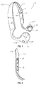
- FIG. 1 is an perspective view of a dual mode headphone in accordance with one aspect of the present application
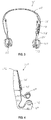
- FIG. 2 is a magnified view of an interior section of the dual mode headphone of FIG. 1 in accordance with one aspect of the present application;
- FIG. 3 is a front view of the dual mode headphone of FIG. 1 in accordance with one aspect of the present application;
- FIG. 4 is a first side view of the dual mode headphone of FIG. 1 in accordance with one aspect of the present application;
- FIG. 5 is a second side view of the dual mode headphone of FIG. 1 in accordance with one aspect of the present application;
- FIG. 6 is another perspective view of the dual mode headphone of FIG. 1 in accordance with one aspect of the present application.
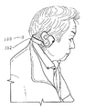
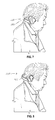
- FIG. 7 is a side view of the dual mode headphone being used in accordance with one aspect of the present application.
- FIG. 8 is a side view of the dual mode headphone being used in accordance with one aspect of the present application.
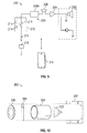
- FIG. 9 is a block diagram of a dual mode headphone circuit used in the dual mode headphone of FIG. 1 in accordance with one aspect of the present application.
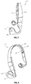
- FIG. 10 is an exploded perspective view of a dual-output acoustic transducer module used in the dual mode headphone in accordance with one aspect of the present application.
- the present disclosure relates to a wireless headphone having a dual-output acoustic transducer module.
- the dual-output acoustic transducer module may combine an audio speaker with a piezoelectric bone-conductive transducer. This may allow a user to use the wireless headphones in a dual mode wherein the dual-output acoustic transducer module may be worn over the ears to allow the sound waves to be transmitted through a speaker to the ear drum, or anywhere on the skull for bone conductive transmission of sound waves through bones in the user's skull.
- the dual mode wireless headphone 100 may be worn over the ears to allow the sound waves to be transmitted to the ear drum, or anywhere on the skull for bone conductive transmission of sound waves through bones in the user's skull.
- the dual mode headphone 100 may have a band 102 .
- the band 102 may be used to secure the dual mode wireless headphone 100 on a head and/or neck of a user.
- the band 102 may be semi-rigid. This may allow the band 102 to conform to a shape and size of the head and/or neck of the user.
- the band 102 may be “U” shaped. However, this is shown as one example and should not be seen in a limiting manner.
- the band 102 may be similar to an eyeglass frame having stems which engage and contact the side of the user's head.
- the band 102 may also be clips which attach to the ears of the user.
- the housing 104 may be formed of different geometrical configurations. In the present embodiment, the housing 104 may be tubular in shape. However, this is shown as an example and should not be seen in a limiting manner.
- the housing 104 may be an enclosure having an open section 106 .
- the open section 106 may be covered by a meshing 108 .
- the meshing 108 may be a foam meshing.
- a foam meshing may allow for the housing 104 to more comfortably sit on the ears and/or skull of the user.
- the housing 104 may be used to store and hold a dual-output acoustic module 202 ( FIGS. 9-10 ) forming a part of a dual mode headphone circuit 200 .
- the housing 104 may have a plurality of openings 110 .
- the openings 110 may be formed in a side of the housing 104 .
- the openings 110 may also be formed on an exterior side 102 B of the band 102 .
- the openings 110 may allow air flow through the housing 104 .
- the above are only shown as examples and should not be seen in a limiting manner.
- the openings 110 may be formed in other areas without departing from the spirit and scope of the present invention.
- Each dual-output module 202 may be coupled together by wiring 112 .
- the wiring 112 may be secured within a channel 114 formed within an interior section 102 A of the band 102 .
- a second housing 116 may be formed and positioned above one of the housing 104 .
- the second housing may be used to store and hold the other components of the dual mode headphone circuit 200 ( FIG. 6 ) which may be described below.
- the second housing 116 may have control buttons 118 .
- the control buttons 118 may be used to control operation of the dual mode headphone circuit 200 .
- the dual mode headphone circuit 200 may be shown.
- the dual mode headphone circuit 200 may have a dual-output acoustic transducer module 202 .
- the dual-output acoustic transducer module 202 may allow sound waves to be transmitted to the ear drum, or use bone conductive transmission to transmit the sound waves through bones in the user's skull.
- An amplifier 204 may be coupled to the dual-output acoustic transducer module 202 .
- the amplifier 204 may be used to control the signal strength being sent to the dual-output acoustic transducer module 202 .
- the amplifier 204 may also filter out noise in the signal being received by the amplifier 204 .
- the dual mode headphone circuit 200 may have a receiver 206 .
- the receiver 206 may be coupled to the amplifier 204 .
- the receiver 206 may be used to receive radio waves from an electronic device 210 such as a portable music player, smart phone or the like.
- the electronic device 210 may transmit radio signals which may be received by the receiver 206 and sent to the dual-output acoustic module 202 via the amplifier 204 .
- the electronic device 210 may play music which may be transmitted to the receiver 206 so that a user may listen to the music via the dual mode headphone 100 .
- the receiver 206 may be a Bluetooth receiver.
- the receiver 206 may be a transmitter/receiver 206 A.
- the transmitter/receiver 206 A may be used so that signals may be sent to and from the dual mode headphone circuit 200 and the electronic device 210 . Thus, this may allow the dual mode headphone circuit 200 to receive signals such as music from the electronic device 210 as well as transmit signals such as control signals back to the electronic device 210 .
- the control signals may be used to control operation of the electronic device such as controlling which songs are being played, pause the music, as well as other functions.
- the transmitter/receiver 206 A may be a Bluetooth receiver.
- the dual mode headphone circuit 200 may have a microphone 208 .
- the microphone 208 may convert sound waves into electrical signals.
- the microphone 208 may be coupled to the amplifier 204 . If the microphone 208 is working in conjunction with the electronic device 210 , the microphone 206 may need to transmit signals to the electronic device 210 .
- the microphone 208 may be a Bluetooth microphone.
- the Bluetooth microphone may work with the electronic device 210 to transmit radio waves between the microphone 206 and the electronic device 210 such as a smart phone.
- the microphone 208 may work with transmitter/receiver 206 A to transmit signals to the electronic device 210 .
- the dual mode headphone circuit 200 may have a control panel 212 .
- the control panel 212 having control devices 214 .
- the control devices 214 may be buttons, switches or similar devices to control operation of the dual mode headphone circuit 200 .
- the control device 214 may be an ON/OFF switch, a volume control mechanism, a selection switch for determining a mode of operation (sound waves to be transmitted to the ear drum, bone conductive transmission through bones in the user's skull and/or both).
- the dual mode headphone circuit 200 may be powered by a power source 216 .
- the power source 216 may be a DC power supply such as a battery.
- the power supply 216 may be a rechargeable battery.
- the dual mode headphone circuit 200 may have a charging port 218 .
- the charging port may allow a user to connect the dual mode headphone circuit 200 to a charging source.
- the charging port 218 may be a Universal Serial Bus (USB) charging port.
- USB Universal Serial Bus
- the dual-output acoustic transducer module 202 may be comprised of a plurality of components. As may be seen in FIG. 9 may have piezoelectric transducer 300 .
- the piezoelectric transducer 300 may convert electric signals into mechanical vibrations in order to sends sound to the inner ear through the cranial bones.
- a loudspeaker 302 may be coupled to the piezoelectric transducer 300 .
- the loudspeaker 302 may include a speaker and driver housed within an enclosure.
- the loudspeaker 302 may be any type of loudspeaker 302 used for headphone applications.
- the piezoelectric transducer 300 may be coupled to the loudspeaker 302 through a connector tube 304 .
- the loudspeaker 302 may be positioned behind the piezoelectric transducer 300 .
- a convex escutcheon plate 306 may be coupled to the piezoelectric transducer 300 and positioned over the connector tube 306 .
- the escutcheon plate 306 may be fitted to cover the dual-output acoustic transducer module 202 .
- the escutcheon plate 306 may have a plurality of vent holes for comfort and seamless fitting to the skin.
- the dual-output acoustic transducer module 202 may be encapsulated by a material 308 .
- the material 308 may be a soft polymer material.
- the module is sealed and isolated from the surrounding. Thus, there is minimal to no sound leakage from the side and back of the module.
- the encapsulation of the module also serves as a resonating chamber to improve the sound wave delivered. Concentric stepping groves may be incorporated on the inside of the enclosure so as to minimize sound wave emission via the exterior of the enclosure.
- the user may use the control devices 214 to select a mode of operation for the dual mode headphone 100 .
- the user may select for either the loudspeaker 302 , the piezoelectric transducer 300 and/or both the loudspeaker 302 and the piezoelectric transducer 300 to be operational.
- the user may position the dual mode headphone 100 so that the housing 104 is positioned within the ears of the user as shown in FIG. 8 or on the skull of the user as shown in FIG. 7 .
- audible control of the piezoelectric transducer 300 and/or the loudspeaker 302 maybe done wirelessly through a smart phone application.
- volume, balance, equalizer as well as other audible controls may be embedded and controlled through a smart phone application.
- the advantages of this module include, without limitation, is that it provides seamless connection between the transducer module 202 and the skull.
- the dual mode headphone 100 can be worn over the ears, or anywhere on the skull. It allows the user to select both loudspeaker 302 and piezoelectric transducer 300 , or either mode.
- the dual mode headphone 100 offers high-fidelity full spectrum audio waves without overwhelming dB that damages the inner ear. For the hearing impaired, this offers an affordable and comfortable alternative to expensive prescription hearing aids.
- Bone conductive mode can be selected when the user desires privacy and do not want any “leakage” of the audio signals from the loudspeaker.
Landscapes
- Engineering & Computer Science (AREA)
- Physics & Mathematics (AREA)
- Acoustics & Sound (AREA)
- Signal Processing (AREA)
- Manufacturing & Machinery (AREA)
- Headphones And Earphones (AREA)
Abstract
A dual mode headphone has a band positioning the dual mode headphone on one of a head or neck of a user. A pair of first housings is provided wherein one of the first housings is formed on each end of the band. A dual mode headphone circuit is provided and has a dual-output acoustic transducer module positioned in each of the pair of first housings. The dual-output acoustic transducer module allowing for both air conduction and bone conduction of sound waves.
Description
- The present patent application claims the benefit of U.S. Provisional Application No. 62/404,092, filed Oct. 4, 2016, entitled “DUAL-OUTPUT ACOUSTIC TRANSDUCER AND METHOD THEREFOR”, in the name of the same inventor and which is incorporated herein by reference in its entirety.
- The present application generally relates to an audio wave delivery system, and, more particularly, to an audio wave delivery system that incorporates both a loudspeaker and a piezoelectric bone-conductive transducer in one integrated module.
- Headphones are a pair of small listening devices that are designed to be worn on or around the head over the ears of a user. Conventional audio headphones incorporate magnetic-coil loudspeakers, which convert electrical signals into audio signals via air pressure waves. The acoustic waves cause the eardrum membrane to vibrate, which sends the audio signals to the auditory nerves.
- Many headphones suffer from sound quality issues. These issues may be exacerbated due to outside noise. Unfortunately, many people have a tendency to increase the volume of the headphones to compensate for the sound quality issues and/or to drown out the outside noise.
- With the advent of portable music players, earbuds became a popular alternative to headphones. Earbuds are generally comprised of small speakers which may be inserted into the user's ear canal. Earbuds are typically less expensive than headphones, much lighter and far less bulky. Unfortunately, earbuds deliver inferior sound quality, especially when it comes to bass tones. Earbuds don't filter out external noise very well, so earbud-wearers tend to crank up the volume which may damage the user's hearing.
- First generation “hearing aids” are similar to earbuds in that they generally require insertion of the loudspeakers into the ear canals and boosts the dB of the audio signal. Hearing aids are uncomfortable to wear and can potentially further damage the delicate inner-ear components.
- Recently, bone-conductive technology has been utilized in both headphones and hearing aids. Bone conduction transmits sound waves through the bones in the user's skull. The vibrations reach the cochlea, or inner ear, which converts them to electrical impulses that travel the auditory nerve to the brain. This is generally accomplished by using a piezoelectric ceramic transducer. To accomplish efficient audio signal transfer, the bone-conductive transducer has to be in direct contact with the skull bone. The headphone/hearing aid is generally installed either in-canal or behind-ear and requires tedious adjustments by an audiologist. Bone-conductive headphones and hearing aids generally require frequent battery replacement. Also, since the ear passage remains unblocked, headphone users generally are able to hear external noises around them.
- Therefore, it would be desirable to provide an apparatus and method that overcome the above problems.
- In accordance with one embodiment, a dual mode headphone is disclosed. The dual mode headphone has a band positioning the dual mode headphone on one of a head or neck of a user. A pair of first housings is provided wherein one of the first housings is formed on each end of the band. A dual mode headphone circuit is provided. The dual mode headphone circuit has a dual-output acoustic transducer module positioned in each of the pair of first housings. The dual-output acoustic transducer module allowing for both air conduction and bone conduction of sound waves.
- In accordance with one embodiment, a dual mode headphone is disclosed. The dual mode headphone has a band positioning the dual mode headphone on one of a head or neck of a user. A dual mode headphone circuit is provided and has a dual-output acoustic transducer module positioned on opposing ends of the band. The dual-output acoustic transducer module allowing for both air conduction and bone conduction of sound waves.
- In accordance with one embodiment, a dual mode headphone is disclosed. The dual mode headphone has a band positioning the dual mode headphone on one of a head or neck of a user. A pair of first housings is provided, wherein one of the first housings is formed on each end of the band. A dual mode headphone circuit is provided. The dual mode headphone circuit has a dual-output acoustic transducer module positioned in each of the pair of first housings, the dual-output acoustic transducer module allowing for both air conduction and bone conduction of sound waves. An amplifier is coupled to the dual-output acoustic transducer module. A microphone is coupled to the amplifier. A transmitter/receiver is coupled to the amplifier. A control unit is coupled to the dual-output acoustic transducer module.
- The present application is further detailed with respect to the following drawings. These figures are not intended to limit the scope of the present application but rather illustrate certain attributes thereof.
-
FIG. 1 is an perspective view of a dual mode headphone in accordance with one aspect of the present application; -
FIG. 2 is a magnified view of an interior section of the dual mode headphone ofFIG. 1 in accordance with one aspect of the present application; -
FIG. 3 is a front view of the dual mode headphone ofFIG. 1 in accordance with one aspect of the present application; -
FIG. 4 is a first side view of the dual mode headphone ofFIG. 1 in accordance with one aspect of the present application; -
FIG. 5 is a second side view of the dual mode headphone ofFIG. 1 in accordance with one aspect of the present application; -
FIG. 6 is another perspective view of the dual mode headphone ofFIG. 1 in accordance with one aspect of the present application; -
FIG. 7 is a side view of the dual mode headphone being used in accordance with one aspect of the present application; -
FIG. 8 is a side view of the dual mode headphone being used in accordance with one aspect of the present application; -
FIG. 9 is a block diagram of a dual mode headphone circuit used in the dual mode headphone ofFIG. 1 in accordance with one aspect of the present application; and -
FIG. 10 is an exploded perspective view of a dual-output acoustic transducer module used in the dual mode headphone in accordance with one aspect of the present application. - The description set forth below in connection with the appended drawings is intended as a description of presently preferred embodiments of the disclosure and is not intended to represent the only forms in which the present disclosure may be constructed and/or utilized. The description sets forth the functions and the sequence of steps for constructing and operating the disclosure in connection with the illustrated embodiments. It is to be understood, however, that the same or equivalent functions and sequences may be accomplished by different embodiments that are also intended to be encompassed within the spirit and scope of this disclosure.
- The present disclosure relates to a wireless headphone having a dual-output acoustic transducer module. The dual-output acoustic transducer module may combine an audio speaker with a piezoelectric bone-conductive transducer. This may allow a user to use the wireless headphones in a dual mode wherein the dual-output acoustic transducer module may be worn over the ears to allow the sound waves to be transmitted through a speaker to the ear drum, or anywhere on the skull for bone conductive transmission of sound waves through bones in the user's skull.
- Referring now to the
FIGS. 1-8 , a dualmode wireless headphone 100 may be seen. The dualmode wireless headphone 100 may be worn over the ears to allow the sound waves to be transmitted to the ear drum, or anywhere on the skull for bone conductive transmission of sound waves through bones in the user's skull. - The
dual mode headphone 100 may have aband 102. Theband 102 may be used to secure the dualmode wireless headphone 100 on a head and/or neck of a user. Theband 102 may be semi-rigid. This may allow theband 102 to conform to a shape and size of the head and/or neck of the user. In the embodiment shown in theFIGS. 1-8 , theband 102 may be “U” shaped. However, this is shown as one example and should not be seen in a limiting manner. For example, theband 102 may be similar to an eyeglass frame having stems which engage and contact the side of the user's head. Theband 102 may also be clips which attach to the ears of the user. - Located on opposing ends of the
band 102 may be ahousing 104. Thehousing 104 may be formed of different geometrical configurations. In the present embodiment, thehousing 104 may be tubular in shape. However, this is shown as an example and should not be seen in a limiting manner. - The
housing 104 may be an enclosure having anopen section 106. Theopen section 106 may be covered by a meshing 108. In accordance with one embodiment, the meshing 108 may be a foam meshing. A foam meshing may allow for thehousing 104 to more comfortably sit on the ears and/or skull of the user. - The
housing 104 may be used to store and hold a dual-output acoustic module 202 (FIGS. 9-10 ) forming a part of a dualmode headphone circuit 200. In accordance with one embodiment, thehousing 104 may have a plurality ofopenings 110. In the embodiment shown, theopenings 110 may be formed in a side of thehousing 104. Theopenings 110 may also be formed on anexterior side 102B of theband 102. Theopenings 110 may allow air flow through thehousing 104. The above are only shown as examples and should not be seen in a limiting manner. Theopenings 110 may be formed in other areas without departing from the spirit and scope of the present invention. - Each dual-
output module 202 may be coupled together by wiring 112. Thewiring 112 may be secured within achannel 114 formed within an interior section 102A of theband 102. - A
second housing 116 may be formed and positioned above one of thehousing 104. The second housing may be used to store and hold the other components of the dual mode headphone circuit 200 (FIG. 6 ) which may be described below. Thesecond housing 116 may havecontrol buttons 118. Thecontrol buttons 118 may be used to control operation of the dualmode headphone circuit 200. - Referring to
FIG. 9 , the dualmode headphone circuit 200 may be shown. The dualmode headphone circuit 200. The dualmode headphone circuit 200 may have a dual-outputacoustic transducer module 202. The dual-outputacoustic transducer module 202 may allow sound waves to be transmitted to the ear drum, or use bone conductive transmission to transmit the sound waves through bones in the user's skull. - An
amplifier 204 may be coupled to the dual-outputacoustic transducer module 202. Theamplifier 204 may be used to control the signal strength being sent to the dual-outputacoustic transducer module 202. Theamplifier 204 may also filter out noise in the signal being received by theamplifier 204. - The dual
mode headphone circuit 200 may have areceiver 206. Thereceiver 206 may be coupled to theamplifier 204. Thereceiver 206 may be used to receive radio waves from anelectronic device 210 such as a portable music player, smart phone or the like. Theelectronic device 210 may transmit radio signals which may be received by thereceiver 206 and sent to the dual-outputacoustic module 202 via theamplifier 204. For example, theelectronic device 210 may play music which may be transmitted to thereceiver 206 so that a user may listen to the music via thedual mode headphone 100. In accordance with one embodiment, thereceiver 206 may be a Bluetooth receiver. - In accordance with one embodiment, the
receiver 206 may be a transmitter/receiver 206A. The transmitter/receiver 206A may be used so that signals may be sent to and from the dualmode headphone circuit 200 and theelectronic device 210. Thus, this may allow the dualmode headphone circuit 200 to receive signals such as music from theelectronic device 210 as well as transmit signals such as control signals back to theelectronic device 210. The control signals may be used to control operation of the electronic device such as controlling which songs are being played, pause the music, as well as other functions. In accordance with one embodiment, the transmitter/receiver 206A may be a Bluetooth receiver. - The dual
mode headphone circuit 200 may have amicrophone 208. Themicrophone 208. Themicrophone 208 may convert sound waves into electrical signals. In the present embodiment, themicrophone 208 may be coupled to theamplifier 204. If themicrophone 208 is working in conjunction with theelectronic device 210, themicrophone 206 may need to transmit signals to theelectronic device 210. In accordance with one embodiment, themicrophone 208 may be a Bluetooth microphone. The Bluetooth microphone may work with theelectronic device 210 to transmit radio waves between themicrophone 206 and theelectronic device 210 such as a smart phone. Alternatively, themicrophone 208 may work with transmitter/receiver 206A to transmit signals to theelectronic device 210. - The dual
mode headphone circuit 200 may have acontrol panel 212. Thecontrol panel 212 havingcontrol devices 214. Thecontrol devices 214 may be buttons, switches or similar devices to control operation of the dualmode headphone circuit 200. For example, thecontrol device 214 may be an ON/OFF switch, a volume control mechanism, a selection switch for determining a mode of operation (sound waves to be transmitted to the ear drum, bone conductive transmission through bones in the user's skull and/or both). - The dual
mode headphone circuit 200 may be powered by apower source 216. Thepower source 216 may be a DC power supply such as a battery. In accordance with one embodiment, thepower supply 216 may be a rechargeable battery. If a rechargeable battery is used, the dualmode headphone circuit 200 may have a chargingport 218. The charging port may allow a user to connect the dualmode headphone circuit 200 to a charging source. In accordance with one embodiment, the chargingport 218 may be a Universal Serial Bus (USB) charging port. - The dual-output
acoustic transducer module 202 may be comprised of a plurality of components. As may be seen inFIG. 9 may havepiezoelectric transducer 300. Thepiezoelectric transducer 300 may convert electric signals into mechanical vibrations in order to sends sound to the inner ear through the cranial bones. Aloudspeaker 302 may be coupled to thepiezoelectric transducer 300. Theloudspeaker 302 may include a speaker and driver housed within an enclosure. Theloudspeaker 302 may be any type ofloudspeaker 302 used for headphone applications. - The
piezoelectric transducer 300 may be coupled to theloudspeaker 302 through aconnector tube 304. In general, theloudspeaker 302 may be positioned behind thepiezoelectric transducer 300. - A
convex escutcheon plate 306 may be coupled to thepiezoelectric transducer 300 and positioned over theconnector tube 306. Theescutcheon plate 306 may be fitted to cover the dual-outputacoustic transducer module 202. Theescutcheon plate 306 may have a plurality of vent holes for comfort and seamless fitting to the skin. - The dual-output
acoustic transducer module 202 may be encapsulated by amaterial 308. In accordance with one embodiment, thematerial 308 may be a soft polymer material. By encapsulating the module, the module is sealed and isolated from the surrounding. Thus, there is minimal to no sound leakage from the side and back of the module. The encapsulation of the module also serves as a resonating chamber to improve the sound wave delivered. Concentric stepping groves may be incorporated on the inside of the enclosure so as to minimize sound wave emission via the exterior of the enclosure. - In operation, the user may use the
control devices 214 to select a mode of operation for thedual mode headphone 100. The user may select for either theloudspeaker 302, thepiezoelectric transducer 300 and/or both theloudspeaker 302 and thepiezoelectric transducer 300 to be operational. Based on the mode of operation selected, the user may position thedual mode headphone 100 so that thehousing 104 is positioned within the ears of the user as shown inFIG. 8 or on the skull of the user as shown inFIG. 7 . - In accordance with one embodiment, audible control of the
piezoelectric transducer 300 and/or theloudspeaker 302 maybe done wirelessly through a smart phone application. For example, volume, balance, equalizer as well as other audible controls may be embedded and controlled through a smart phone application. - The advantages of this module include, without limitation, is that it provides seamless connection between the
transducer module 202 and the skull. Thedual mode headphone 100 can be worn over the ears, or anywhere on the skull. It allows the user to select bothloudspeaker 302 andpiezoelectric transducer 300, or either mode. For music lovers, thedual mode headphone 100 offers high-fidelity full spectrum audio waves without overwhelming dB that damages the inner ear. For the hearing impaired, this offers an affordable and comfortable alternative to expensive prescription hearing aids. Bone conductive mode can be selected when the user desires privacy and do not want any “leakage” of the audio signals from the loudspeaker. - While embodiments of the disclosure have been described in terms of various specific embodiments, those skilled in the art will recognize that the embodiments of the disclosure may be practiced with modifications within the spirit and scope of the claims
Claims (20)
1. A dual mode headphone comprising:
a band positioning the dual mode headphone on one of a head or neck of a user;
a pair of first housings, wherein one of the first housings is formed on each end of the band;
a dual mode headphone circuit having a dual-output acoustic transducer module positioned in each of the pair of first housings, the dual-output acoustic transducer module allowing for both air conduction and bone conduction of sound waves.
2. The dual mode headphone of claim 1 , wherein the dual-output acoustic transducer module comprises:
a piezoelectric transducer; and
a loudspeaker.
3. The dual mode headphone of claim 1 , wherein the dual-output acoustic transducer module comprises:
a piezoelectric transducer; and
a loudspeaker positioned behind the piezoelectric transducer.
4. The dual mode headphone of claim 2 , wherein the dual-output acoustic transducer module comprises:
a connector tube positioned between the piezoelectric transducer and the loudspeaker; and
an escutcheon plate coupled to the piezoelectric transducer and positioned over the connector tube.
5. The dual mode headphone of claim 4 , wherein the escutcheon plate has a plurality of vent holes.
6. The dual mode headphone of claim 4 , wherein the dual-output acoustic transducer module comprises an encapsulation material covering the dual-output acoustic transducer module.
7. The dual mode headphone of claim 6 , wherein the encapsulation material is a soft polymer material.
8. The dual mode headphone of claim 1 , wherein the dual mode headphone circuit comprises a microphone coupled to the dual-output acoustic transducer module.
9. The dual mode headphone of claim 1 , wherein the dual mode headphone circuit comprises a microphone coupled to the dual-output acoustic transducer module, the microphone being a Bluetooth microphone.
10. The dual mode headphone of claim 1 , wherein the dual mode headphone circuit comprises:
an amplifier coupled to the dual-output acoustic transducer module;
a microphone coupled to the amplifier;
a transmitter/receiver coupled to the amplifier; and
a control unit coupled to the dual-output acoustic transducer module.
11. The dual mode headphone of claim 10 , wherein the dual mode headphone circuit comprises a power source powering the dual mode headphone circuit.
12. The dual mode headphone of claim 10 , wherein the dual mode headphone circuit comprises a charging port coupled to the power source.
13. A dual mode headphone comprising:
a band positioning the dual mode headphone on one of a head or neck of a user; and
a dual mode headphone circuit having a dual-output acoustic transducer module positioned on opposing ends of the band, the dual-output acoustic transducer module allowing for both air conduction and bone conduction of sound waves.
14. The dual mode headphone of claim 13 , comprising:
a pair of first housings, wherein one of the first housings is formed on each end of the band, wherein the dual-output acoustic transducer module is positioned within each of the first pair of housings;
wherein the dual-output acoustic transducer module comprises:
a piezoelectric transducer; and
a loudspeaker.
15. The dual mode headphone of claim 14 , wherein the dual-output acoustic transducer module comprises:
a connector tube positioned between the piezoelectric transducer and the loudspeaker;
an escutcheon plate coupled to the piezoelectric transducer and positioned over the connector tube, wherein the escutcheon plate has a plurality of vent holes; and
an encapsulation material covering the dual-output acoustic transducer module.
16. The dual mode headphone of claim 14 , wherein the dual mode headphone circuit comprises a microphone coupled to the dual-output acoustic transducer module, the microphone being a Bluetooth microphone.
17. The dual mode headphone of claim 14 , wherein the dual mode headphone circuit comprises:
an amplifier coupled to the dual-output acoustic transducer module;
a microphone coupled to the amplifier;
a transmitter/receiver coupled to the amplifier;
a control unit coupled to the dual-output acoustic transducer module; and
a power source powering the dual mode headphone circuit.
18. A dual mode headphone comprising:
a band positioning the dual mode headphone on one of a head or neck of a user;
a pair of first housings, wherein one of the first housings is formed on each end of the band; and
a dual mode headphone circuit comprising:
a dual-output acoustic transducer module positioned in each of the pair of first housings, the dual-output acoustic transducer module allowing for both air conduction and bone conduction of sound waves;
an amplifier coupled to the dual-output acoustic transducer module;
a microphone coupled to the amplifier;
a transmitter/receiver coupled to the amplifier; and
a control unit coupled to the dual-output acoustic transducer module.
19. The dual mode headphone of claim 18 , wherein the dual-output acoustic transducer module comprises:
a piezoelectric transducer;
a loudspeaker positioned behind the piezoelectric transducer;
a connector tube positioned between the piezoelectric transducer and the loudspeaker;
an escutcheon plate coupled to the piezoelectric transducer and positioned over the connector tube, wherein the escutcheon plate has a plurality of vent holes; and
an encapsulation material covering the dual-output acoustic transducer module.
20. The dual mode headphone of claim 18 , wherein the dual mode headphone circuit comprises:
a power source powering the dual mode headphone circuit; and
a charging port coupled to the power source.
Priority Applications (2)
| Application Number | Priority Date | Filing Date | Title |
|---|---|---|---|
| US15/435,598 US10142735B2 (en) | 2016-10-04 | 2017-02-17 | Dual mode headphone and method therefor |
| US16/181,642 US10743094B2 (en) | 2016-10-04 | 2018-11-06 | Helmet having dual mode headphone and method therefor |
Applications Claiming Priority (2)
| Application Number | Priority Date | Filing Date | Title |
|---|---|---|---|
| US201662404092P | 2016-10-04 | 2016-10-04 | |
| US15/435,598 US10142735B2 (en) | 2016-10-04 | 2017-02-17 | Dual mode headphone and method therefor |
Related Child Applications (1)
| Application Number | Title | Priority Date | Filing Date |
|---|---|---|---|
| US16/181,642 Continuation-In-Part US10743094B2 (en) | 2016-10-04 | 2018-11-06 | Helmet having dual mode headphone and method therefor |
Publications (2)
| Publication Number | Publication Date |
|---|---|
| US20180098153A1 true US20180098153A1 (en) | 2018-04-05 |
| US10142735B2 US10142735B2 (en) | 2018-11-27 |
Family
ID=61759120
Family Applications (1)
| Application Number | Title | Priority Date | Filing Date |
|---|---|---|---|
| US15/435,598 Expired - Fee Related US10142735B2 (en) | 2016-10-04 | 2017-02-17 | Dual mode headphone and method therefor |
Country Status (1)
| Country | Link |
|---|---|
| US (1) | US10142735B2 (en) |
Cited By (5)
| Publication number | Priority date | Publication date | Assignee | Title |
|---|---|---|---|---|
| CN108668189A (en) * | 2018-05-15 | 2018-10-16 | 深圳市云中飞电子有限公司 | A kind of noise-reduction method, device and bone conduction earphone for bone conduction earphone |
| US20200084531A1 (en) * | 2018-09-07 | 2020-03-12 | Plantronics, Inc. | Conformable Headset Earloop for Stability and Comfort |
| WO2020140461A1 (en) * | 2019-01-05 | 2020-07-09 | 深圳市韶音科技有限公司 | Speaker device |
| USD957361S1 (en) * | 2021-01-06 | 2022-07-12 | Jian Chen | Bone conduction headphones |
| EP4415388A3 (en) * | 2021-10-22 | 2024-11-13 | Shenzhen Shokz Co., Ltd. | Earphones |
Families Citing this family (5)
| Publication number | Priority date | Publication date | Assignee | Title |
|---|---|---|---|---|
| CN108886645A (en) * | 2016-03-29 | 2018-11-23 | 索尼公司 | Audio reproducing apparatus |
| USD1061473S1 (en) * | 2017-04-05 | 2025-02-11 | Sonusmed Incorporated | Headset |
| US10631075B1 (en) * | 2018-11-12 | 2020-04-21 | Bose Corporation | Open ear audio device with bone conduction speaker |
| US11659312B2 (en) | 2019-08-05 | 2023-05-23 | Audiolineout Llc | Earphone with solid body |
| US12339521B2 (en) | 2020-10-27 | 2025-06-24 | Skullcandy, Inc. | Eyeglasses with associated true wireless earbuds |
Citations (4)
| Publication number | Priority date | Publication date | Assignee | Title |
|---|---|---|---|---|
| US20160277823A1 (en) * | 2015-03-20 | 2016-09-22 | Jetvox Acoustic Corp. | Piezoelectric ceramic dual-band bass-enhanced earpiece |
| US9601682B2 (en) * | 2014-12-02 | 2017-03-21 | Taiyo Yuden Co., Ltd. | Electroacoustic transducer |
| US9860647B2 (en) * | 2015-05-08 | 2018-01-02 | Transound Electronics Co., Ltd. | High sound quality piezoelectric speaker |
| US9973857B2 (en) * | 2014-12-17 | 2018-05-15 | Taiyo Yuden Co., Ltd. | Piezoelectric speaker and electroacoustic transducer |
Family Cites Families (8)
| Publication number | Priority date | Publication date | Assignee | Title |
|---|---|---|---|---|
| US4821323A (en) * | 1988-02-19 | 1989-04-11 | Papiernik Raymond S | Stereo headphone |
| US7031475B2 (en) * | 2004-03-09 | 2006-04-18 | Matsushita Electric Industrial Co., Ltd. | All-in-one headset |
| US20110170723A1 (en) * | 2005-08-29 | 2011-07-14 | William Ryann | Earpiece headset assembly |
| US20080112581A1 (en) * | 2006-11-09 | 2008-05-15 | Stanley Kim | Vibrating earphone with enhanced base sound effect |
| EP2731358A1 (en) * | 2008-02-11 | 2014-05-14 | Bone Tone Communications Ltd. | A sound system and a method for providing sound |
| CA2807808A1 (en) * | 2010-08-09 | 2012-02-16 | #3248362 Nova Scotia Limited | Personal listening device |
| JP5900887B2 (en) * | 2011-04-04 | 2016-04-06 | 国立大学法人金沢大学 | Ear hole-mounted bone conduction device |
| US9788097B2 (en) * | 2016-01-29 | 2017-10-10 | Big O LLC | Multi-function bone conducting headphones |
-
2017
- 2017-02-17 US US15/435,598 patent/US10142735B2/en not_active Expired - Fee Related
Patent Citations (4)
| Publication number | Priority date | Publication date | Assignee | Title |
|---|---|---|---|---|
| US9601682B2 (en) * | 2014-12-02 | 2017-03-21 | Taiyo Yuden Co., Ltd. | Electroacoustic transducer |
| US9973857B2 (en) * | 2014-12-17 | 2018-05-15 | Taiyo Yuden Co., Ltd. | Piezoelectric speaker and electroacoustic transducer |
| US20160277823A1 (en) * | 2015-03-20 | 2016-09-22 | Jetvox Acoustic Corp. | Piezoelectric ceramic dual-band bass-enhanced earpiece |
| US9860647B2 (en) * | 2015-05-08 | 2018-01-02 | Transound Electronics Co., Ltd. | High sound quality piezoelectric speaker |
Cited By (14)
| Publication number | Priority date | Publication date | Assignee | Title |
|---|---|---|---|---|
| CN108668189A (en) * | 2018-05-15 | 2018-10-16 | 深圳市云中飞电子有限公司 | A kind of noise-reduction method, device and bone conduction earphone for bone conduction earphone |
| US20200084531A1 (en) * | 2018-09-07 | 2020-03-12 | Plantronics, Inc. | Conformable Headset Earloop for Stability and Comfort |
| US10687138B2 (en) * | 2018-09-07 | 2020-06-16 | Plantronics, Inc. | Conformable headset earloop for stability and comfort |
| US11968494B2 (en) | 2019-01-05 | 2024-04-23 | Shenzhen Shokz Co., Ltd. | Loudspeaker apparatus |
| US11336991B2 (en) | 2019-01-05 | 2022-05-17 | Shenzhen Shokz Co., Ltd. | Loudspeaker apparatus |
| US11363365B2 (en) | 2019-01-05 | 2022-06-14 | Shenzhen Shokz Co., Ltd. | Loudspeaker apparatus |
| US11617033B2 (en) | 2019-01-05 | 2023-03-28 | Shenzhen Shokz Co., Ltd. | Loudspeaker apparatus |
| US11917358B2 (en) | 2019-01-05 | 2024-02-27 | Shenzhen Shokz Co., Ltd. | Loudspeaker apparatus |
| WO2020140461A1 (en) * | 2019-01-05 | 2020-07-09 | 深圳市韶音科技有限公司 | Speaker device |
| US12231840B2 (en) | 2019-01-05 | 2025-02-18 | Shenzhen Shokz Co., Ltd. | Loudspeaker apparatus |
| USD957361S1 (en) * | 2021-01-06 | 2022-07-12 | Jian Chen | Bone conduction headphones |
| EP4415388A3 (en) * | 2021-10-22 | 2024-11-13 | Shenzhen Shokz Co., Ltd. | Earphones |
| US12490008B2 (en) | 2021-10-22 | 2025-12-02 | Shenzhen Shokz Co., Ltd. | Headphones |
| US12610172B2 (en) | 2021-10-22 | 2026-04-21 | Shenzhen Shokz Co., Ltd. | Headphones |
Also Published As
| Publication number | Publication date |
|---|---|
| US10142735B2 (en) | 2018-11-27 |
Similar Documents
| Publication | Publication Date | Title |
|---|---|---|
| US10743094B2 (en) | Helmet having dual mode headphone and method therefor | |
| US10142735B2 (en) | Dual mode headphone and method therefor | |
| US7925038B2 (en) | Earset assembly | |
| EP3522568B1 (en) | A hearing aid including a vibrator touching a pinna | |
| US6681022B1 (en) | Two-way communication earpiece | |
| USRE48424E1 (en) | Custom fit in-ear monitors utilizing a single piece driver module | |
| US8311259B2 (en) | In-ear earphone | |
| CN103125125B (en) | Communication headset and ambient sound is relayed the method for headphone wearer | |
| KR101457928B1 (en) | On-site, custom fitted hearing equalizer | |
| US20020039427A1 (en) | Audio apparatus | |
| US20070014423A1 (en) | Behind-the-ear auditory device | |
| US20080112581A1 (en) | Vibrating earphone with enhanced base sound effect | |
| WO2007011806A2 (en) | Behind-the-ear auditory device | |
| KR101771607B1 (en) | Dual type apparatus for listening | |
| CN108886645A (en) | Audio reproducing apparatus | |
| JP2021034775A (en) | earphone | |
| JP2023538849A (en) | Earpiece port configuration | |
| JP2010527213A (en) | Body vibration small acoustic receiver | |
| JP2007228508A (en) | Receiver | |
| JP5548790B1 (en) | Open earphone with sound collecting microphone and hearing aid | |
| US20090154738A1 (en) | Mixable earphone-microphone device with sound attenuation | |
| EP2668792A1 (en) | Hearing aid | |
| KR20060043937A (en) | earphone | |
| CN218071801U (en) | Hearing assistance device | |
| CN117412212B (en) | Mixed conduction earphone device at inner side of tragus and design method thereof |
Legal Events
| Date | Code | Title | Description |
|---|---|---|---|
| STCF | Information on status: patent grant |
Free format text: PATENTED CASE |
|
| FEPP | Fee payment procedure |
Free format text: MAINTENANCE FEE REMINDER MAILED (ORIGINAL EVENT CODE: REM.); ENTITY STATUS OF PATENT OWNER: SMALL ENTITY |
|
| LAPS | Lapse for failure to pay maintenance fees |
Free format text: PATENT EXPIRED FOR FAILURE TO PAY MAINTENANCE FEES (ORIGINAL EVENT CODE: EXP.); ENTITY STATUS OF PATENT OWNER: SMALL ENTITY |
|
| STCH | Information on status: patent discontinuation |
Free format text: PATENT EXPIRED DUE TO NONPAYMENT OF MAINTENANCE FEES UNDER 37 CFR 1.362 |
|
| FP | Lapsed due to failure to pay maintenance fee |
Effective date: 20221127 |