US20180098148A1 - Electronic device - Google Patents
Electronic device Download PDFInfo
- Publication number
- US20180098148A1 US20180098148A1 US15/820,703 US201715820703A US2018098148A1 US 20180098148 A1 US20180098148 A1 US 20180098148A1 US 201715820703 A US201715820703 A US 201715820703A US 2018098148 A1 US2018098148 A1 US 2018098148A1
- Authority
- US
- United States
- Prior art keywords
- sound
- electronic device
- sound outlet
- conditioner
- outlet
- Prior art date
- Legal status (The legal status is an assumption and is not a legal conclusion. Google has not performed a legal analysis and makes no representation as to the accuracy of the status listed.)
- Granted
Links
Images


Classifications
-
- H—ELECTRICITY
- H04—ELECTRIC COMMUNICATION TECHNIQUE
- H04R—LOUDSPEAKERS, MICROPHONES, GRAMOPHONE PICK-UPS OR LIKE ACOUSTIC ELECTROMECHANICAL TRANSDUCERS; ELECTRIC HEARING AIDS; PUBLIC ADDRESS SYSTEMS
- H04R1/00—Details of transducers, loudspeakers or microphones
- H04R1/20—Arrangements for obtaining desired frequency or directional characteristics
- H04R1/32—Arrangements for obtaining desired frequency or directional characteristics for obtaining desired directional characteristic only
- H04R1/34—Arrangements for obtaining desired frequency or directional characteristics for obtaining desired directional characteristic only by using a single transducer with sound reflecting, diffracting, directing or guiding means
- H04R1/345—Arrangements for obtaining desired frequency or directional characteristics for obtaining desired directional characteristic only by using a single transducer with sound reflecting, diffracting, directing or guiding means for loudspeakers
-
- H—ELECTRICITY
- H04—ELECTRIC COMMUNICATION TECHNIQUE
- H04R—LOUDSPEAKERS, MICROPHONES, GRAMOPHONE PICK-UPS OR LIKE ACOUSTIC ELECTROMECHANICAL TRANSDUCERS; ELECTRIC HEARING AIDS; PUBLIC ADDRESS SYSTEMS
- H04R1/00—Details of transducers, loudspeakers or microphones
- H04R1/02—Casings; Cabinets ; Supports therefor; Mountings therein
-
- H—ELECTRICITY
- H04—ELECTRIC COMMUNICATION TECHNIQUE
- H04R—LOUDSPEAKERS, MICROPHONES, GRAMOPHONE PICK-UPS OR LIKE ACOUSTIC ELECTROMECHANICAL TRANSDUCERS; ELECTRIC HEARING AIDS; PUBLIC ADDRESS SYSTEMS
- H04R2499/00—Aspects covered by H04R or H04S not otherwise provided for in their subgroups
- H04R2499/10—General applications
- H04R2499/11—Transducers incorporated or for use in hand-held devices, e.g. mobile phones, PDA's, camera's
Definitions
- the present invention relates to an electronic device and elements thereof, and more particularly to an electronic device being able to change position where sound is transmitted and elements thereof to facilitate the change.
- an electronic device such as mobile cell phone, tablet, or notebook
- the electronic device's speaker receives signals from a control unit and converts these signals into corresponding acoustic waves that can be heard by a human being.
- the speaker is arranged on the lower side of the electronic device to be near the user.
- one objective of the present invention is to provide an electronic device, which has at least two sound outlets, sound is selectively transmitted to the outside via one of the two sound outlets, so as to provide a high-quality listening experience.
- an electronic device in accordance with one embodiment of the disclosure, includes a sliding groove, a speaker and a sound conditioner.
- the sliding groove extending from the first side wall to the second side wall along a predetermined direction.
- a first sound outlet and a second sound outlet are connected to the sliding groove and respectively positioned adjacent to the first side wall and the second side wall.
- the speaker is positioned relative to the first sound outlet.
- the sound conditioner extends along the sliding groove for a length that is greater than the distance between the first sound outlet and the second sound outlet.
- the sound conditioner is slidably positioned in the sliding groove so as to allow the sound produced by the speaker to be transmitted to the outside via either the first sound outlet or the second sound outlet.
- the area of the first sound outlet is the same as the area of the second sound outlet, and the depth of a portion of the sliding groove that corresponds to the first sound outlet is the same as the depth of a portion of the sliding groove that corresponds to the second sound outlet.
- the sound conditioner includes a tube structure, a front opening is formed on an upper side wall of the tube structure and arranged adjacent to the first end portion of the tube structure, and a rear opening is formed at the tube structure and arranged adjacent to the second end portion of the tube structure, the first end being opposite to the second end.
- the area of the front opening is the same as the area of the rear opening.
- the area of the rear opening is the same as the area of the first sound outlet or the area of the second sound outlet.
- the sound conditioner includes a plate extending along the sliding groove.
- the sound produced by the speaker is directly transmitted to the outside of the electronic device via the first sound outlet.
- the sound produced by the speaker is transmitted to the outside of the electronic device via the sound guiding passage in the sound conditioner and the second sound outlet.
- the first sound outlet and the speaker are positioned at two sides of the sound conditioner.
- the first sound outlet and the second sound outlet are positioned at the same bottom side wall of the sliding groove.
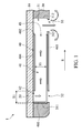
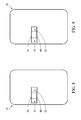
- FIG. 1 shows a cross-sectional schematic view of an electronic device having a sound conditioner in a first position, in accordance with some embodiments of the disclosure.
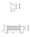
- FIG. 2A shows a schematic view of a sliding groove, in accordance with some embodiment of the disclosure.
- FIG. 2B shows a schematic view of a speaker, in accordance with some embodiment of the disclosure
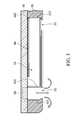
- FIG. 3 shows a cross-sectional schematic view of an electronic device having a sound conditioner in a second position, in accordance with some embodiments of the disclosure.
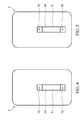
- FIG. 4 shows a cross-sectional schematic view of an electronic device having a sound conditioner in a first position, in accordance with some embodiments of the disclosure.
- FIG. 5 shows a cross-sectional schematic view of an electronic device having a sound conditioner in a second position, in accordance with some embodiments of the disclosure.
- FIG. 6 shows a cross-sectional schematic view of an electronic device having a sound conditioner in a first position, in accordance with some embodiments of the disclosure.
- FIG. 7 shows a cross-sectional schematic view of an electronic device having a sound conditioner in a second position, in accordance with some embodiments of the disclosure.
- FIG. 8 shows a cross-sectional schematic view of an electronic device having a sound conditioner in a first position, in accordance with some embodiments of the disclosure.
- FIG. 9 shows a cross-sectional schematic view of an electronic device having a sound conditioner in a second position, in accordance with some embodiments of the disclosure.
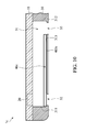
- FIG. 10 shows a cross-sectional schematic view of an electronic device having a sound conditioner in a first position, in accordance with some embodiments of the disclosure.
- a layer overlying another layer may indicate not only that the layer directly contacts the other layer, but also that the layer does not directly contact the other layer, there being one or more intermediate layers disposed between the layer and the other layer.
- FIG. 1 shows a cross-sectional schematic view of an electronic device 1 , in accordance with a first embodiment of the disclosure.
- the electronic device 1 for example, is a mobile cell phone, a tablet, or a notebook and includes a first substrate 10 , a speaker 20 , a second substrate 30 , and a sound conditioner 40 .
- the elements of the electronic device 1 can be added to or omitted, and the invention should not be limited by the embodiment.
- the first substrate 10 is a circuit board
- the second substrate 30 is a portion of a housing of the electronic device 1 .
- the second substrate 30 may be made of metal or plastic material.
- the first substrate 10 and other elements of the electronic device 1 (such as control chip) are positioned in a space defined by the housing.
- the disclosure should not be limited thereto.
- the first substrate 10 is a portion of a housing of the electronic device 1
- elements of the electronic device 1 such as circuit board and control chip (not shown in figures) are positioned in a space defined by the housing.
- the second substrate 30 is a protective cover detachably connected to the first substrate 10 .
- the first substrate 10 and the second substrate 30 may be made of metal or plastic material.
- the speaker 20 is configured to receive electric signals and convert the signals to sound.
- the speaker 20 is disposed on the first substrate 10 .
- the sound produced by the speaker 20 is transmitted to the outside of the electronic device 1 via sound outlets 32 and 33 on the second substrate 30 .
- the configuration of the sound outlets 32 and 33 are described below.
- the second substrate 30 is arranged to be immediately adjacent to the first substrate 10 .
- a sliding groove 31 is formed on one side of the second substrate 30 that faces the first substrate 10 .
- the sliding groove 31 extends from the first side wall 311 to the second side wall 312 with unit width and depth (i.e., the sliding groove has unit cross section).
- a bottom side wall 313 connects the first side wall 311 to the second side wall 312 .
- the sound outlet 32 is formed on the bottom side wall 313 and connects to the sliding groove 31 .
- the sound outlet 33 is formed on the bottom side wall 313 and connects to the sliding groove 31 .
- the sound outlet 32 is spaced from the sound outlet 33 by a distance, not connected to one the other.
- the distance between the sound outlet 32 and the sound outlet 33 may range from about 1 mm to about 300 mm.
- the sound outlet 32 is referred to first sound outlet
- the sound outlet 33 is referred to second sound outlet.
- the first sound outlet 32 has a length of L 2 and a width of W 1 , the area of the first sound outlet 32 is the length L 1 times the width W 1 .
- the second sound outlet 33 has a length of L 3 and a width of W 1 , the area of the second sound outlet 33 is the length L 3 times the width W 1 .
- the length L 1 equals the length L 3 , so that the area of the first sound outlet 32 is the same as the second sound outlet 33 .
- the area of the first sound outlet 32 and the area of the second sound outlet 33 are the same as the area of the speaker 20 (i.e., length S 1 times width S 2 of the speaker 20 , as shown in FIG. 2B ).
- the sound conditioner 40 is slidably disposed in the sliding groove 31 so as to change the sound outlet for transmitting sound from the speaker 20 .
- the sound conditioner 40 is a tube structure extending form a first end portion 401 to a second end portion 402 .
- the length of the sound conditioner 40 from the first end portion 401 to the second end portion 402 is greater than the distance L 2 ( FIG. 2A ) between the first sound outlet 32 and the second sound outlet 33 .
- the sound conditioner 40 defines a sound guiding passage 41 therein.
- the sound conditioner 40 is a hollow rectangular tube.
- the cross section of the sound conditioner 40 is the same as the area of the speaker 20 (i.e., length S 1 times width S 2 of the speaker 20 , as shown in FIG. 2B ).
- the sound conditioner 40 includes a lower side wall 403 and an upper side wall 404 . After the sound conditioner 40 is disposed in the sliding groove 31 , the lower side wall 403 is in contact with the bottom side wall 313 , and the upper side wall 404 is aligned with the sliding groove 31 .
- a front opening 42 is formed at the upper side wall 404 of the sound conditioner 40 and arranged adjacent to the first end 401
- a rear opening 43 is formed at the sound conditioner 40 and arranged adjacent to the second end portion 402 . Except for the front opening 42 and the rear opening 43 , other side wall of the sound conditioner 40 is closed.
- the first end portion 401 of the sound conditioner 40 faces the first side wall 311 of the sliding groove 31
- the second end portion 402 of the sound conditioner 40 faces the second side wall 312 of the sliding groove 31 .
- the distance H 1 between the upper side wall 404 and lower side wall 403 of the sound conditioner 40 is the same as the height H 1 of the speaker 20 .
- the area of the front opening 42 of the sound conditioner 40 is the same as the area of the speaker 20 .
- the area of the rear opening 43 of the sound conditioner 40 is the same as the area of the speaker 20 .
- the cross section of the sound guiding passage 41 is the same as the area of the speaker 20 .
- the inner wall of the sound guiding passage 41 is a smooth surface, low energy loss or very little energy loss occurs during the transmission of the sound in the sound guiding passage 41 .
- the sound conditioner 40 is arranged at a first position. At this time, the first sound outlet 32 is blocked by the sound conditioner 40 , the sound from the speaker 20 passes through the front opening 42 , the sound guiding passage 41 , the rear opening 43 and enters a section of the sliding groove 31 corresponding to the second sound outlet 33 . As a result, the sound from the speaker 20 is transmitted to the outside of the electronic device 1 via the second sound outlet 33 .
- the sound conditioner 40 To transmit sound from the speaker 20 via the first sound outlet 32 , the sound conditioner 40 is moved along a direction as indicated by the arrow S of FIG. 1 to a second position as shown in FIG. 3 . At this time, the second sound outlet 33 is blocked by the sound conditioner 40 , the sound from the speaker 20 enters a section of the sliding groove 31 corresponding to the first sound outlet 32 . As a result, the sound from the speaker 20 is transmitted to the outside of the electronic device 1 via the first sound outlet 32 .
- the position of the sound conditioner 40 is changed manually.
- the position of the sound conditioner 40 is changed by a built-in driving module (not shown in figures) as a detection member (not shown in figures) detects changes in the orientation of the electronic device 1 .
- the vacant volume above the second sound outlet 33 in the sliding groove 31 when the sound conditioner 40 is in the first position ( FIG. 1 ) is the same as the vacant volume above the first sound outlet 32 in the sliding groove 31 as the sound conditioner 40 is in the second position ( FIG. 3 ).
- the sound pressure and the sound intensity of the sound from the two sound outlets 32 and 33 heard by the user are identical. Therefore, the user can select one of the sound outlets that are arranged at two different positions to transmit sound according to demand, so as to have a better listening experience with high sound quality.
- the configuration of the sliding groove 31 can be changed according to design.
- the sliding groove 31 extends along the longitudinal axis of the electronic device 1 .
- the sound conditioner 40 is slidably positioned in the sliding groove 31 along the extension direction thereof to be located in the first position ( FIG. 4 ) and the second position ( FIG. 5 ).
- the sound conditioner 40 is in the first position, the sound is transmitted to the outside of the electronic device 1 via the second sound outlet 33 near the center of the electronic device 1 .
- the sound conditioner 40 is in the second position, the sound is transmitted to the outside of the electronic device 1 via the first sound outlet 32 near the lateral side on the longitudinal axis of the electronic device 1 .
- the sliding groove 31 extends along a direction slanted to the longitudinal axis of the electronic device 1 a.
- the sound conditioner 40 is slidably positioned in the sliding groove 31 along the extension direction thereof to be located in the first position ( FIG. 6 ) and the second position ( FIG. 7 ).
- the sound conditioner 40 is in the first position, the sound is transmitted to the outside of the electronic device 1 a via the second sound outlet 33 near the center of the electronic device 1 a.
- the sound conditioner 40 is in the second position, the sound is transmitted to the outside of the electronic device 1 a via the first sound outlet 32 near a corner of the electronic device 1 a.
- the sliding groove 31 extends along the short axis of the electronic device 1 b.
- the sound conditioner 40 is slidably positioned in the sliding groove 31 along the extension direction thereof to be located in the first position ( FIG. 8 ) and the second position ( FIG. 9 ).
- the sound conditioner 40 is in the first position, the sound is transmitted to the outside of the electronic device 1 b via the second sound outlet 33 near the center of the electronic device 1 b.
- the sound conditioner 40 is in the second position, the sound is transmitted to the outside of the electronic device 1 b via the first sound outlet 32 near the lateral side on the short axis of the electronic device 1 b.
- FIG. 10 shows a cross-sectional schematic view of an electronic device 1 c, in accordance with some embodiments of the disclosure.
- elements that are identical with or similar to the elements of the electronic device 1 shown in FIG. 1 are designated by the same reference number, and the features thereof are not repeated for the purpose of brevity.
- the differences between the electronic device 1 and the electronic device 1 c include the sound conditioner 40 of the electronic device 1 being replaced by a sound conditioner 40 c.
- the sound conditioner 40 c includes a plate structure disposed in the sliding groove 31 , wherein the lower side wall of the sound conditioner 40 c is in contact with the bottom side wall of the sliding groove 31 .
- the sound conditioner 40 c has a width that is the same as the width of the sliding groove 31 .
- the length of the sound conditioner 40 c is greater than the distance between the first sound outlet 32 and the second sound outlet 33 .
- the electronic device of the disclosure includes a movable sound conditioner. By changing the position of the sound conditioner, the user can select one of the sound outlets to transmit sound without degradation on sound quality, so as to have a better listening experience.
Landscapes
- Health & Medical Sciences (AREA)
- Otolaryngology (AREA)
- Physics & Mathematics (AREA)
- Engineering & Computer Science (AREA)
- Acoustics & Sound (AREA)
- Signal Processing (AREA)
- Telephone Set Structure (AREA)
- Details Of Audible-Bandwidth Transducers (AREA)
Abstract
Description
- This application is a continuation of application Ser. No. 15/141,793, filed on Apr. 28, 2016, which claims the priority of Taiwan Patent Application No. 104136132, filed on Nov. 3, 2015, the entirety of which is incorporated by reference herein.
- The present invention relates to an electronic device and elements thereof, and more particularly to an electronic device being able to change position where sound is transmitted and elements thereof to facilitate the change.
- Generally, an electronic device (such as mobile cell phone, tablet, or notebook) includes one speaker. The electronic device's speaker receives signals from a control unit and converts these signals into corresponding acoustic waves that can be heard by a human being. To make sure that the user can hear the sound converted by the speaker, the speaker is arranged on the lower side of the electronic device to be near the user.
- However, since there is only one sound outlet formed on a conventional electronic device, sound produced by the speaker is broadcast at one single side of the electronic device, which may result in an unpleasant listening experience for the user.
- Accordingly, one objective of the present invention is to provide an electronic device, which has at least two sound outlets, sound is selectively transmitted to the outside via one of the two sound outlets, so as to provide a high-quality listening experience.
- In accordance with one embodiment of the disclosure, an electronic device is provided. The electronic device includes a sliding groove, a speaker and a sound conditioner. The sliding groove extending from the first side wall to the second side wall along a predetermined direction. A first sound outlet and a second sound outlet are connected to the sliding groove and respectively positioned adjacent to the first side wall and the second side wall. The speaker is positioned relative to the first sound outlet. The sound conditioner extends along the sliding groove for a length that is greater than the distance between the first sound outlet and the second sound outlet. The sound conditioner is slidably positioned in the sliding groove so as to allow the sound produced by the speaker to be transmitted to the outside via either the first sound outlet or the second sound outlet.
- In the above-mentioned embodiment, the area of the first sound outlet is the same as the area of the second sound outlet, and the depth of a portion of the sliding groove that corresponds to the first sound outlet is the same as the depth of a portion of the sliding groove that corresponds to the second sound outlet.
- In the above-mentioned embodiment, the sound conditioner includes a tube structure, a front opening is formed on an upper side wall of the tube structure and arranged adjacent to the first end portion of the tube structure, and a rear opening is formed at the tube structure and arranged adjacent to the second end portion of the tube structure, the first end being opposite to the second end.
- In the above-mentioned embodiment, the area of the front opening is the same as the area of the rear opening.
- In the above-mentioned embodiment, the area of the rear opening is the same as the area of the first sound outlet or the area of the second sound outlet.
- In the above-mentioned embodiment, the sound conditioner includes a plate extending along the sliding groove.
- In the above-mentioned embodiment, when the second outlet is blocked by the sound conditioner, the sound produced by the speaker is directly transmitted to the outside of the electronic device via the first sound outlet.
- In the above-mentioned embodiment, when the first outlet is blocked by the sound conditioner, the sound produced by the speaker is transmitted to the outside of the electronic device via the sound guiding passage in the sound conditioner and the second sound outlet.
- In the above-mentioned embodiment, the first sound outlet and the speaker are positioned at two sides of the sound conditioner.
- In the above-mentioned embodiment, the first sound outlet and the second sound outlet are positioned at the same bottom side wall of the sliding groove.
- The present invention can be more fully understood by reading the subsequent detailed description and examples with references made to the accompanying drawings, wherein:
-
FIG. 1 shows a cross-sectional schematic view of an electronic device having a sound conditioner in a first position, in accordance with some embodiments of the disclosure. -
FIG. 2A shows a schematic view of a sliding groove, in accordance with some embodiment of the disclosure. -
FIG. 2B shows a schematic view of a speaker, in accordance with some embodiment of the disclosure -
FIG. 3 shows a cross-sectional schematic view of an electronic device having a sound conditioner in a second position, in accordance with some embodiments of the disclosure. -
FIG. 4 shows a cross-sectional schematic view of an electronic device having a sound conditioner in a first position, in accordance with some embodiments of the disclosure. -
FIG. 5 shows a cross-sectional schematic view of an electronic device having a sound conditioner in a second position, in accordance with some embodiments of the disclosure. -
FIG. 6 shows a cross-sectional schematic view of an electronic device having a sound conditioner in a first position, in accordance with some embodiments of the disclosure. -
FIG. 7 shows a cross-sectional schematic view of an electronic device having a sound conditioner in a second position, in accordance with some embodiments of the disclosure. -
FIG. 8 shows a cross-sectional schematic view of an electronic device having a sound conditioner in a first position, in accordance with some embodiments of the disclosure. -
FIG. 9 shows a cross-sectional schematic view of an electronic device having a sound conditioner in a second position, in accordance with some embodiments of the disclosure. -
FIG. 10 shows a cross-sectional schematic view of an electronic device having a sound conditioner in a first position, in accordance with some embodiments of the disclosure. - In the following detailed description, for purposes of explanation, numerous specific details and embodiments are set forth in order to provide a thorough understanding of the present disclosure. The specific elements and configurations described in the following detailed description are set forth in order to clearly describe the present disclosure. It will be apparent, however, that the exemplary embodiments set forth herein are used merely for the purpose of illustration, and the inventive concept may be embodied in various forms without being limited to those exemplary embodiments. In addition, the drawings of different embodiments may use like and/or corresponding numerals to denote like and/or corresponding elements in order to clearly describe the present disclosure. However, the use of like and/or corresponding numerals in the drawings of different embodiments does not suggest any correlation between different embodiments.
- It should be noted that the elements or devices in the drawings of the present disclosure may be present in any form or configuration known to those skilled in the art. In addition, the expression “a layer overlying another layer”, “a layer is disposed above another layer”, “a layer is disposed on another layer” and “a layer is disposed over another layer” may indicate not only that the layer directly contacts the other layer, but also that the layer does not directly contact the other layer, there being one or more intermediate layers disposed between the layer and the other layer.
- In this specification, relative expressions are used. For example, “lower”, “bottom”, “higher” or “top” are used to describe the position of one element relative to another. It should be appreciated that if a device is flipped upside down, an element at a “lower” side will become an element at a “higher” side.
- The terms “about” and “substantially” typically mean +/−20% of the stated value, more typically +/−10% of the stated value and even more typically +/−5% of the stated value. The stated value of the present disclosure is an approximate value. When there is no specific description, the stated value includes the meaning of “about” or “substantially”.
-
FIG. 1 shows a cross-sectional schematic view of anelectronic device 1, in accordance with a first embodiment of the disclosure. Theelectronic device 1, for example, is a mobile cell phone, a tablet, or a notebook and includes afirst substrate 10, aspeaker 20, asecond substrate 30, and asound conditioner 40. The elements of theelectronic device 1 can be added to or omitted, and the invention should not be limited by the embodiment. - In some embodiments, the
first substrate 10 is a circuit board, and thesecond substrate 30 is a portion of a housing of theelectronic device 1. Thesecond substrate 30 may be made of metal or plastic material. Thefirst substrate 10 and other elements of the electronic device 1 (such as control chip) are positioned in a space defined by the housing. However, the disclosure should not be limited thereto. In some other embodiments, thefirst substrate 10 is a portion of a housing of theelectronic device 1, elements of theelectronic device 1, such as circuit board and control chip (not shown in figures), are positioned in a space defined by the housing. Thesecond substrate 30 is a protective cover detachably connected to thefirst substrate 10. Thefirst substrate 10 and thesecond substrate 30 may be made of metal or plastic material. - The
speaker 20 is configured to receive electric signals and convert the signals to sound. In some embodiments, thespeaker 20 is disposed on thefirst substrate 10. The sound produced by thespeaker 20 is transmitted to the outside of theelectronic device 1 viasound outlets second substrate 30. The configuration of thesound outlets - In some embodiments, the
second substrate 30 is arranged to be immediately adjacent to thefirst substrate 10. A slidinggroove 31 is formed on one side of thesecond substrate 30 that faces thefirst substrate 10. In some embodiments, the slidinggroove 31 extends from thefirst side wall 311 to thesecond side wall 312 with unit width and depth (i.e., the sliding groove has unit cross section). Abottom side wall 313 connects thefirst side wall 311 to thesecond side wall 312. - At the position near the
first side wall 311, thesound outlet 32 is formed on thebottom side wall 313 and connects to the slidinggroove 31. In addition, at the position adjacent to thesecond side wall 312, thesound outlet 33 is formed on thebottom side wall 313 and connects to the slidinggroove 31. Thesound outlet 32 is spaced from thesound outlet 33 by a distance, not connected to one the other. The distance between thesound outlet 32 and thesound outlet 33 may range from about 1 mm to about 300 mm. For the purpose of illustration, in the following descriptions, thesound outlet 32 is referred to first sound outlet, and thesound outlet 33 is referred to second sound outlet. - Referring to
FIG. 2A , thefirst sound outlet 32 has a length of L2 and a width of W1, the area of thefirst sound outlet 32 is the length L1 times the width W1. Additionally, thesecond sound outlet 33 has a length of L3 and a width of W1, the area of thesecond sound outlet 33 is the length L3 times the width W1. In some embodiments, the length L1 equals the length L3, so that the area of thefirst sound outlet 32 is the same as thesecond sound outlet 33. In some embodiments, the area of thefirst sound outlet 32 and the area of thesecond sound outlet 33 are the same as the area of the speaker 20 (i.e., length S1 times width S2 of thespeaker 20, as shown inFIG. 2B ). The advantages that result from the above features will be illustrated below. - Referring to
FIG. 1 , thesound conditioner 40 is slidably disposed in the slidinggroove 31 so as to change the sound outlet for transmitting sound from thespeaker 20. In some embodiments, thesound conditioner 40 is a tube structure extending form afirst end portion 401 to asecond end portion 402. The length of thesound conditioner 40 from thefirst end portion 401 to thesecond end portion 402 is greater than the distance L2 (FIG. 2A ) between thefirst sound outlet 32 and thesecond sound outlet 33. - The
sound conditioner 40 defines asound guiding passage 41 therein. In some embodiments, thesound conditioner 40 is a hollow rectangular tube. The cross section of thesound conditioner 40 is the same as the area of the speaker 20 (i.e., length S1 times width S2 of thespeaker 20, as shown inFIG. 2B ). In some embodiments, thesound conditioner 40 includes alower side wall 403 and anupper side wall 404. After thesound conditioner 40 is disposed in the slidinggroove 31, thelower side wall 403 is in contact with thebottom side wall 313, and theupper side wall 404 is aligned with the slidinggroove 31. - A
front opening 42 is formed at theupper side wall 404 of thesound conditioner 40 and arranged adjacent to thefirst end 401, and arear opening 43 is formed at thesound conditioner 40 and arranged adjacent to thesecond end portion 402. Except for thefront opening 42 and therear opening 43, other side wall of thesound conditioner 40 is closed. In some embodiments, after thesound conditioner 40 is positioned in the slidinggroove 31, thefirst end portion 401 of thesound conditioner 40 faces thefirst side wall 311 of the slidinggroove 31, and thesecond end portion 402 of thesound conditioner 40 faces thesecond side wall 312 of the slidinggroove 31. - In some embodiments, the distance H1 between the
upper side wall 404 andlower side wall 403 of thesound conditioner 40 is the same as the height H1 of thespeaker 20. Additionally, the area of thefront opening 42 of thesound conditioner 40 is the same as the area of thespeaker 20. Moreover, the area of therear opening 43 of thesound conditioner 40 is the same as the area of thespeaker 20. As a result, the cross section of thesound guiding passage 41 is the same as the area of thespeaker 20. In some embodiments, the inner wall of thesound guiding passage 41 is a smooth surface, low energy loss or very little energy loss occurs during the transmission of the sound in thesound guiding passage 41. With the above-mentioned features, the sonic energy as the sound is entering thesound guiding passage 41 via thefront opening 42 is substantially equal to the sonic energy as the sound is leaving thesound guiding passage 41 via therear opening 43. - The operation method of the
electronic device 1, in accordance with some embodiments of the disclosure, is described below. - Referring to
FIG. 1 , to transmit sound from thespeaker 20 via thesecond sound outlet 33, thesound conditioner 40 is arranged at a first position. At this time, thefirst sound outlet 32 is blocked by thesound conditioner 40, the sound from thespeaker 20 passes through thefront opening 42, thesound guiding passage 41, therear opening 43 and enters a section of the slidinggroove 31 corresponding to thesecond sound outlet 33. As a result, the sound from thespeaker 20 is transmitted to the outside of theelectronic device 1 via thesecond sound outlet 33. - To transmit sound from the
speaker 20 via thefirst sound outlet 32, thesound conditioner 40 is moved along a direction as indicated by the arrow S ofFIG. 1 to a second position as shown inFIG. 3 . At this time, thesecond sound outlet 33 is blocked by thesound conditioner 40, the sound from thespeaker 20 enters a section of the slidinggroove 31 corresponding to thefirst sound outlet 32. As a result, the sound from thespeaker 20 is transmitted to the outside of theelectronic device 1 via thefirst sound outlet 32. - In some embodiments, the position of the
sound conditioner 40 is changed manually. Alternatively, the position of thesound conditioner 40 is changed by a built-in driving module (not shown in figures) as a detection member (not shown in figures) detects changes in the orientation of theelectronic device 1. - It should be noted that the vacant volume above the
second sound outlet 33 in the slidinggroove 31 when thesound conditioner 40 is in the first position (FIG. 1 ) is the same as the vacant volume above thefirst sound outlet 32 in the slidinggroove 31 as thesound conditioner 40 is in the second position (FIG. 3 ). According to the plane source sound transmitting principle, the sound pressure and the sound intensity of the sound from the twosound outlets - The configuration of the sliding
groove 31 can be changed according to design. For example, as shown inFIGS. 4 and 5 , the slidinggroove 31 extends along the longitudinal axis of theelectronic device 1. In addition, thesound conditioner 40 is slidably positioned in the slidinggroove 31 along the extension direction thereof to be located in the first position (FIG. 4 ) and the second position (FIG. 5 ). When thesound conditioner 40 is in the first position, the sound is transmitted to the outside of theelectronic device 1 via thesecond sound outlet 33 near the center of theelectronic device 1. When thesound conditioner 40 is in the second position, the sound is transmitted to the outside of theelectronic device 1 via thefirst sound outlet 32 near the lateral side on the longitudinal axis of theelectronic device 1. - Alternatively, as shown in
FIGS. 6 and 7 , the slidinggroove 31 extends along a direction slanted to the longitudinal axis of the electronic device 1 a. In addition, thesound conditioner 40 is slidably positioned in the slidinggroove 31 along the extension direction thereof to be located in the first position (FIG. 6 ) and the second position (FIG. 7 ). When thesound conditioner 40 is in the first position, the sound is transmitted to the outside of the electronic device 1 a via thesecond sound outlet 33 near the center of the electronic device 1 a. When thesound conditioner 40 is in the second position, the sound is transmitted to the outside of the electronic device 1 a via thefirst sound outlet 32 near a corner of the electronic device 1 a. - Alternatively, as shown in
FIGS. 8 and 9 , the slidinggroove 31 extends along the short axis of theelectronic device 1 b. In addition, thesound conditioner 40 is slidably positioned in the slidinggroove 31 along the extension direction thereof to be located in the first position (FIG. 8 ) and the second position (FIG. 9 ). When thesound conditioner 40 is in the first position, the sound is transmitted to the outside of theelectronic device 1 b via thesecond sound outlet 33 near the center of theelectronic device 1 b. When thesound conditioner 40 is in the second position, the sound is transmitted to the outside of theelectronic device 1 b via thefirst sound outlet 32 near the lateral side on the short axis of theelectronic device 1 b. -
FIG. 10 shows a cross-sectional schematic view of anelectronic device 1 c, in accordance with some embodiments of the disclosure. In the embodiment shown inFIG. 10 , elements that are identical with or similar to the elements of theelectronic device 1 shown inFIG. 1 are designated by the same reference number, and the features thereof are not repeated for the purpose of brevity. The differences between theelectronic device 1 and theelectronic device 1 c include thesound conditioner 40 of theelectronic device 1 being replaced by asound conditioner 40 c. - In some embodiments, the
sound conditioner 40 c includes a plate structure disposed in the slidinggroove 31, wherein the lower side wall of thesound conditioner 40 c is in contact with the bottom side wall of the slidinggroove 31. Thesound conditioner 40 c has a width that is the same as the width of the slidinggroove 31. In addition, in the extension direction of the sliding groove, the length of thesound conditioner 40 c is greater than the distance between thefirst sound outlet 32 and thesecond sound outlet 33. - As shown in
FIG. 10 , when thesound conditioner 40 c is in the first position, sound is transmitted to the outside of theelectronic device 1 c via thesecond sound outlet 33. When thesound conditioner 40 c is in the second position, sound is transmitted to the outside of theelectronic device 1 c via thefirst sound outlet 32. - The electronic device of the disclosure includes a movable sound conditioner. By changing the position of the sound conditioner, the user can select one of the sound outlets to transmit sound without degradation on sound quality, so as to have a better listening experience.
- Although the embodiments and their advantages have been described in detail, it should be understood that various changes, substitutions, and alterations can be made herein without departing from the spirit and scope of the embodiments as defined by the appended claims. Moreover, the scope of the present application is not intended to be limited to the particular embodiments of the process, machine, manufacture, composition of matter, means, methods, and steps described in the specification. As one of ordinary skill in the art will readily appreciate from the disclosure, processes, machines, manufacture, compositions of matter, means, methods, or steps, presently existing or later to be developed, that perform substantially the same function or achieve substantially the same result as the corresponding embodiments described herein may be utilized according to the disclosure. Accordingly, the appended claims are intended to include within their scope such processes, machines, manufacture, compositions of matter, means, methods, or steps. In addition, each claim constitutes a separate embodiment, and the combination of various claims and embodiments are within the scope of the disclosure.
Claims (13)
Priority Applications (1)
| Application Number | Priority Date | Filing Date | Title |
|---|---|---|---|
| US15/820,703 US10194237B2 (en) | 2015-11-03 | 2017-11-22 | Electronic device |
Applications Claiming Priority (4)
| Application Number | Priority Date | Filing Date | Title |
|---|---|---|---|
| TW104136132 | 2015-11-03 | ||
| TW104136132A TWI583202B (en) | 2015-11-03 | 2015-11-03 | Electronic device |
| US15/141,793 US9860632B2 (en) | 2015-11-03 | 2016-04-28 | Electronic device |
| US15/820,703 US10194237B2 (en) | 2015-11-03 | 2017-11-22 | Electronic device |
Related Parent Applications (1)
| Application Number | Title | Priority Date | Filing Date |
|---|---|---|---|
| US15/141,793 Continuation US9860632B2 (en) | 2015-11-03 | 2016-04-28 | Electronic device |
Publications (2)
| Publication Number | Publication Date |
|---|---|
| US20180098148A1 true US20180098148A1 (en) | 2018-04-05 |
| US10194237B2 US10194237B2 (en) | 2019-01-29 |
Family
ID=58637600
Family Applications (2)
| Application Number | Title | Priority Date | Filing Date |
|---|---|---|---|
| US15/141,793 Active US9860632B2 (en) | 2015-11-03 | 2016-04-28 | Electronic device |
| US15/820,703 Active US10194237B2 (en) | 2015-11-03 | 2017-11-22 | Electronic device |
Family Applications Before (1)
| Application Number | Title | Priority Date | Filing Date |
|---|---|---|---|
| US15/141,793 Active US9860632B2 (en) | 2015-11-03 | 2016-04-28 | Electronic device |
Country Status (2)
| Country | Link |
|---|---|
| US (2) | US9860632B2 (en) |
| TW (1) | TWI583202B (en) |
Cited By (3)
| Publication number | Priority date | Publication date | Assignee | Title |
|---|---|---|---|---|
| US10194237B2 (en) * | 2015-11-03 | 2019-01-29 | Acer Incorporated | Electronic device |
| WO2020156207A1 (en) * | 2019-01-29 | 2020-08-06 | Oppo广东移动通信有限公司 | Electronic apparatus |
| US12526577B2 (en) | 2020-11-17 | 2026-01-13 | Samsung Electronics Co., Ltd. | Electronic device comprising speaker and operation method of same |
Families Citing this family (3)
| Publication number | Priority date | Publication date | Assignee | Title |
|---|---|---|---|---|
| CN112261187B (en) * | 2020-10-23 | 2022-04-12 | 维沃移动通信有限公司 | Electronic device |
| CN112272250B (en) * | 2020-10-28 | 2023-08-18 | 维沃移动通信有限公司 | Speaker modules and electronic equipment |
| CN216904953U (en) * | 2021-12-29 | 2022-07-05 | 瑞声光电科技(常州)有限公司 | Electronic terminal |
Citations (12)
| Publication number | Priority date | Publication date | Assignee | Title |
|---|---|---|---|---|
| US6332029B1 (en) * | 1995-09-02 | 2001-12-18 | New Transducers Limited | Acoustic device |
| US6628040B2 (en) * | 2000-02-23 | 2003-09-30 | Sri International | Electroactive polymer thermal electric generators |
| US20030215087A1 (en) * | 2002-05-16 | 2003-11-20 | Huo-Lu Tsai | Mobile phone hands-free kit with a sound-pickup device Mobile phone hands-free kit with a sound-pickup device |
| US20050049016A1 (en) * | 2003-08-25 | 2005-03-03 | Samsung Electronics Co., Ltd. | Port cover unit for electronic equipment |
| US7199166B2 (en) * | 2003-08-22 | 2007-04-03 | Degussa Ag | Radiation-curable resins based on hydrogenated ketone-aldehyde and phenol-aldehyde resins and a process for preparing them |
| US20080139258A1 (en) * | 2006-12-08 | 2008-06-12 | Samsung Electronics., Ltd. | Port cover opening/closing device for portable terminal |
| US20090104950A1 (en) * | 2007-10-17 | 2009-04-23 | Inventec Corporation | Slide type portable electronic device |
| US20110215921A1 (en) * | 2009-06-22 | 2011-09-08 | Mourad Ben Ayed | Systems for wireless authentication based on bluetooth proximity |
| US9380364B2 (en) * | 2014-05-23 | 2016-06-28 | Acer Incorporated | Electronic device and electronic assembly |
| US20160238433A1 (en) * | 2015-02-17 | 2016-08-18 | Qisda (Suzhou) Co., Ltd. | Electronic device |
| US20160327983A1 (en) * | 2015-05-08 | 2016-11-10 | Acer Incorporated | Electronic device |
| US20170127176A1 (en) * | 2015-11-03 | 2017-05-04 | Acer Incorporated | Electronic device |
Family Cites Families (27)
| Publication number | Priority date | Publication date | Assignee | Title |
|---|---|---|---|---|
| US4763111A (en) * | 1984-09-05 | 1988-08-09 | Ryobi Ltd. | Door closer having sound generating function |
| US4726066A (en) * | 1985-11-26 | 1988-02-16 | P. O. Vox Medical, Inc. | Inter-oral speech aid |
| US5402486A (en) * | 1993-12-29 | 1995-03-28 | Wang; Xinxin | Earring compatible telephone handset receiver |
| US20040145859A1 (en) * | 1999-11-04 | 2004-07-29 | Mechanical Research Corp. | Acoustic device |
| EP1583391A1 (en) * | 2004-04-01 | 2005-10-05 | Sony Ericsson Mobile Communications AB | A communications unit with arrangment for loud reproduction of sound |
| EP1757161B1 (en) * | 2004-05-14 | 2016-11-30 | Sonion Nederland B.V. | Dual diaphragm electroacoustic transducer |
| CN201117024Y (en) * | 2007-06-20 | 2008-09-17 | 何文江 | A daily life appliance that wakes up sleeping people with light, smell, and sound |
| US8099144B2 (en) * | 2007-08-20 | 2012-01-17 | Google Inc. | Electronic device with hinge mechanism |
| JP2010068299A (en) * | 2008-09-11 | 2010-03-25 | Yamaha Corp | Earphone |
| US8213668B2 (en) * | 2008-11-04 | 2012-07-03 | Merry Electronics Co., Ltd. | In-ear earphone |
| JP5262702B2 (en) * | 2008-12-26 | 2013-08-14 | ヤマハ株式会社 | Earphone structure and earphone |
| TW201029484A (en) * | 2009-01-23 | 2010-08-01 | E Ten Information Sys Co Ltd | Speaker device output controlling method |
| US8042647B1 (en) * | 2009-03-16 | 2011-10-25 | Robert Layton, Jr. | Speaker side air supply |
| US7967104B2 (en) * | 2009-07-03 | 2011-06-28 | Keith Carter | Shippable speaker box |
| KR101077327B1 (en) * | 2009-10-16 | 2011-10-26 | 엘지이노텍 주식회사 | E-book |
| US8938312B2 (en) * | 2011-04-18 | 2015-01-20 | Sonos, Inc. | Smart line-in processing |
| TW201322784A (en) * | 2011-11-17 | 2013-06-01 | Top Victory Invest Ltd | Electronic device capable of automatically outputting correct channels |
| WO2013092706A1 (en) * | 2011-12-21 | 2013-06-27 | Brüel & Kjær Sound & Vibration Measurement A/S | A microphone test stand for acoustic testing |
| JP2013216168A (en) * | 2012-04-05 | 2013-10-24 | Denso Corp | Vehicle existence notifying device |
| TWM442664U (en) * | 2012-05-23 | 2012-12-01 | Cheng Uei Prec Ind Co Ltd | Adjustable sound box |
| CN103841501B (en) * | 2012-11-20 | 2017-10-24 | 清华大学 | sound chip |
| TWM471725U (en) * | 2013-03-05 | 2014-02-01 | Mao-Liang Liu | Earphone with stage music sound field reproduction |
| WO2014162474A1 (en) * | 2013-04-01 | 2014-10-09 | パイオニア株式会社 | Sound output device for vehicle |
| JP2015041814A (en) * | 2013-08-20 | 2015-03-02 | 船井電機株式会社 | Speaker attachment structure and display device |
| US9232303B2 (en) * | 2013-10-07 | 2016-01-05 | Cellco Partnership | Apparatus for enhancing sound from portable devices |
| CN103618984B (en) * | 2013-12-09 | 2017-04-26 | 歌尔股份有限公司 | Loudspeaker module and manufacturing method thereof |
| CN204442628U (en) * | 2015-03-27 | 2015-07-01 | 捷音特科技股份有限公司 | Range Switching Headphones |
-
2015
- 2015-11-03 TW TW104136132A patent/TWI583202B/en active
-
2016
- 2016-04-28 US US15/141,793 patent/US9860632B2/en active Active
-
2017
- 2017-11-22 US US15/820,703 patent/US10194237B2/en active Active
Patent Citations (13)
| Publication number | Priority date | Publication date | Assignee | Title |
|---|---|---|---|---|
| US6332029B1 (en) * | 1995-09-02 | 2001-12-18 | New Transducers Limited | Acoustic device |
| US6628040B2 (en) * | 2000-02-23 | 2003-09-30 | Sri International | Electroactive polymer thermal electric generators |
| US20030215087A1 (en) * | 2002-05-16 | 2003-11-20 | Huo-Lu Tsai | Mobile phone hands-free kit with a sound-pickup device Mobile phone hands-free kit with a sound-pickup device |
| US7199166B2 (en) * | 2003-08-22 | 2007-04-03 | Degussa Ag | Radiation-curable resins based on hydrogenated ketone-aldehyde and phenol-aldehyde resins and a process for preparing them |
| US20050049016A1 (en) * | 2003-08-25 | 2005-03-03 | Samsung Electronics Co., Ltd. | Port cover unit for electronic equipment |
| US20080139258A1 (en) * | 2006-12-08 | 2008-06-12 | Samsung Electronics., Ltd. | Port cover opening/closing device for portable terminal |
| US20090104950A1 (en) * | 2007-10-17 | 2009-04-23 | Inventec Corporation | Slide type portable electronic device |
| US20110215921A1 (en) * | 2009-06-22 | 2011-09-08 | Mourad Ben Ayed | Systems for wireless authentication based on bluetooth proximity |
| US9380364B2 (en) * | 2014-05-23 | 2016-06-28 | Acer Incorporated | Electronic device and electronic assembly |
| US20160238433A1 (en) * | 2015-02-17 | 2016-08-18 | Qisda (Suzhou) Co., Ltd. | Electronic device |
| US20160327983A1 (en) * | 2015-05-08 | 2016-11-10 | Acer Incorporated | Electronic device |
| US20170127176A1 (en) * | 2015-11-03 | 2017-05-04 | Acer Incorporated | Electronic device |
| US9860632B2 (en) * | 2015-11-03 | 2018-01-02 | Acer Incorporated | Electronic device |
Cited By (3)
| Publication number | Priority date | Publication date | Assignee | Title |
|---|---|---|---|---|
| US10194237B2 (en) * | 2015-11-03 | 2019-01-29 | Acer Incorporated | Electronic device |
| WO2020156207A1 (en) * | 2019-01-29 | 2020-08-06 | Oppo广东移动通信有限公司 | Electronic apparatus |
| US12526577B2 (en) | 2020-11-17 | 2026-01-13 | Samsung Electronics Co., Ltd. | Electronic device comprising speaker and operation method of same |
Also Published As
| Publication number | Publication date |
|---|---|
| TW201717657A (en) | 2017-05-16 |
| US9860632B2 (en) | 2018-01-02 |
| US20170127176A1 (en) | 2017-05-04 |
| US10194237B2 (en) | 2019-01-29 |
| TWI583202B (en) | 2017-05-11 |
Similar Documents
| Publication | Publication Date | Title |
|---|---|---|
| US10194237B2 (en) | Electronic device | |
| CN108336483B (en) | Antenna assembly, electronic equipment and antenna switching method | |
| CN104618570B (en) | Audio capture with multiple microphones | |
| WO2001078354A3 (en) | Hands-free communication device | |
| US20080137896A1 (en) | Headset Capable of Switching Signal Transmissions | |
| KR102569403B1 (en) | mobile terminal | |
| JP2017028477A5 (en) | Image forming apparatus | |
| US20060113143A1 (en) | Acoustic device | |
| CN205081822U (en) | mobile communication terminal | |
| US8804990B2 (en) | Portable apparatus | |
| EP3105673B1 (en) | Display device | |
| CN106714046B (en) | Electronic device | |
| JPWO2011135678A1 (en) | Speaker device | |
| US10887686B2 (en) | Directional microphone | |
| GB2413722A (en) | Multi microphone system for hand-held device | |
| US9497546B2 (en) | Stereo boundary microphone and stereo boundary microphone adapter | |
| US20190132895A1 (en) | Multi-connection device and multi-connection method | |
| US9838778B2 (en) | Speaker and electronic device having the speaker | |
| US7930005B2 (en) | Housing and portable electronic device using same | |
| KR101446611B1 (en) | Two-Way Kernel Type Earphone | |
| JP5200934B2 (en) | Portable terminal device and casing for portable terminal device | |
| CN204669595U (en) | Anti-interference audio connector | |
| CN103914106A (en) | Portable device | |
| JP2009111858A (en) | Charger for mobile electronic device | |
| CN215344651U (en) | Shell assembly and mobile terminal |
Legal Events
| Date | Code | Title | Description |
|---|---|---|---|
| FEPP | Fee payment procedure |
Free format text: ENTITY STATUS SET TO UNDISCOUNTED (ORIGINAL EVENT CODE: BIG.); ENTITY STATUS OF PATENT OWNER: LARGE ENTITY |
|
| AS | Assignment |
Owner name: ACER INCORPORATED, TAIWAN Free format text: ASSIGNMENT OF ASSIGNORS INTEREST;ASSIGNORS:LIU, FENG- MING;CHANG, JIA-REN;REEL/FRAME:044233/0126 Effective date: 20160330 |
|
| STCF | Information on status: patent grant |
Free format text: PATENTED CASE |
|
| MAFP | Maintenance fee payment |
Free format text: PAYMENT OF MAINTENANCE FEE, 4TH YEAR, LARGE ENTITY (ORIGINAL EVENT CODE: M1551); ENTITY STATUS OF PATENT OWNER: LARGE ENTITY Year of fee payment: 4 |