US20180098144A1 - Optical communication interface - Google Patents
Optical communication interface Download PDFInfo
- Publication number
- US20180098144A1 US20180098144A1 US15/285,243 US201615285243A US2018098144A1 US 20180098144 A1 US20180098144 A1 US 20180098144A1 US 201615285243 A US201615285243 A US 201615285243A US 2018098144 A1 US2018098144 A1 US 2018098144A1
- Authority
- US
- United States
- Prior art keywords
- optical
- facing side
- handheld device
- interface
- receiver
- Prior art date
- Legal status (The legal status is an assumption and is not a legal conclusion. Google has not performed a legal analysis and makes no representation as to the accuracy of the status listed.)
- Granted
Links
Images
Classifications
-
- H—ELECTRICITY
- H01—ELECTRIC ELEMENTS
- H01R—ELECTRICALLY-CONDUCTIVE CONNECTIONS; STRUCTURAL ASSOCIATIONS OF A PLURALITY OF MUTUALLY-INSULATED ELECTRICAL CONNECTING ELEMENTS; COUPLING DEVICES; CURRENT COLLECTORS
- H01R13/00—Details of coupling devices of the kinds covered by groups H01R12/70 or H01R24/00 - H01R33/00
- H01R13/02—Contact members
- H01R13/15—Pins, blades or sockets having separate spring member for producing or increasing contact pressure
- H01R13/17—Pins, blades or sockets having separate spring member for producing or increasing contact pressure with spring member on the pin
-
- H—ELECTRICITY
- H04—ELECTRIC COMMUNICATION TECHNIQUE
- H04B—TRANSMISSION
- H04B10/00—Transmission systems employing electromagnetic waves other than radio-waves, e.g. infrared, visible or ultraviolet light, or employing corpuscular radiation, e.g. quantum communication
- H04B10/11—Arrangements specific to free-space transmission, i.e. transmission through air or vacuum
- H04B10/114—Indoor or close-range type systems
- H04B10/1143—Bidirectional transmission
-
- H—ELECTRICITY
- H04—ELECTRIC COMMUNICATION TECHNIQUE
- H04R—LOUDSPEAKERS, MICROPHONES, GRAMOPHONE PICK-UPS OR LIKE ACOUSTIC ELECTROMECHANICAL TRANSDUCERS; ELECTRIC HEARING AIDS; PUBLIC ADDRESS SYSTEMS
- H04R1/00—Details of transducers, loudspeakers or microphones
- H04R1/10—Earpieces; Attachments therefor ; Earphones; Monophonic headphones
- H04R1/1016—Earpieces of the intra-aural type
-
- H—ELECTRICITY
- H01—ELECTRIC ELEMENTS
- H01R—ELECTRICALLY-CONDUCTIVE CONNECTIONS; STRUCTURAL ASSOCIATIONS OF A PLURALITY OF MUTUALLY-INSULATED ELECTRICAL CONNECTING ELEMENTS; COUPLING DEVICES; CURRENT COLLECTORS
- H01R13/00—Details of coupling devices of the kinds covered by groups H01R12/70 or H01R24/00 - H01R33/00
- H01R13/66—Structural association with built-in electrical component
- H01R13/665—Structural association with built-in electrical component with built-in electronic circuit
-
- H—ELECTRICITY
- H01—ELECTRIC ELEMENTS
- H01R—ELECTRICALLY-CONDUCTIVE CONNECTIONS; STRUCTURAL ASSOCIATIONS OF A PLURALITY OF MUTUALLY-INSULATED ELECTRICAL CONNECTING ELEMENTS; COUPLING DEVICES; CURRENT COLLECTORS
- H01R13/00—Details of coupling devices of the kinds covered by groups H01R12/70 or H01R24/00 - H01R33/00
- H01R13/66—Structural association with built-in electrical component
- H01R13/717—Structural association with built-in electrical component with built-in light source
- H01R13/7175—Light emitting diodes (LEDs)
-
- H—ELECTRICITY
- H01—ELECTRIC ELEMENTS
- H01R—ELECTRICALLY-CONDUCTIVE CONNECTIONS; STRUCTURAL ASSOCIATIONS OF A PLURALITY OF MUTUALLY-INSULATED ELECTRICAL CONNECTING ELEMENTS; COUPLING DEVICES; CURRENT COLLECTORS
- H01R13/00—Details of coupling devices of the kinds covered by groups H01R12/70 or H01R24/00 - H01R33/00
- H01R13/73—Means for mounting coupling parts to apparatus or structures, e.g. to a wall
-
- H—ELECTRICITY
- H04—ELECTRIC COMMUNICATION TECHNIQUE
- H04B—TRANSMISSION
- H04B10/00—Transmission systems employing electromagnetic waves other than radio-waves, e.g. infrared, visible or ultraviolet light, or employing corpuscular radiation, e.g. quantum communication
- H04B10/11—Arrangements specific to free-space transmission, i.e. transmission through air or vacuum
- H04B10/114—Indoor or close-range type systems
- H04B10/116—Visible light communication
-
- H—ELECTRICITY
- H04—ELECTRIC COMMUNICATION TECHNIQUE
- H04B—TRANSMISSION
- H04B10/00—Transmission systems employing electromagnetic waves other than radio-waves, e.g. infrared, visible or ultraviolet light, or employing corpuscular radiation, e.g. quantum communication
- H04B10/40—Transceivers
-
- H—ELECTRICITY
- H04—ELECTRIC COMMUNICATION TECHNIQUE
- H04R—LOUDSPEAKERS, MICROPHONES, GRAMOPHONE PICK-UPS OR LIKE ACOUSTIC ELECTROMECHANICAL TRANSDUCERS; ELECTRIC HEARING AIDS; PUBLIC ADDRESS SYSTEMS
- H04R1/00—Details of transducers, loudspeakers or microphones
- H04R1/10—Earpieces; Attachments therefor ; Earphones; Monophonic headphones
- H04R1/1025—Accumulators specially adapted for earpieces; Arrangements specially adapted for charging thereof
-
- H—ELECTRICITY
- H04—ELECTRIC COMMUNICATION TECHNIQUE
- H04R—LOUDSPEAKERS, MICROPHONES, GRAMOPHONE PICK-UPS OR LIKE ACOUSTIC ELECTROMECHANICAL TRANSDUCERS; ELECTRIC HEARING AIDS; PUBLIC ADDRESS SYSTEMS
- H04R2420/00—Details of connection covered by H04R, not provided for in its groups
- H04R2420/07—Applications of wireless loudspeakers or wireless microphones
Definitions
- the present specification relates to systems, methods, apparatuses, devices, articles of manufacture and instructions for an optical communications interface.
- an optical communication interface for a handheld device wherein the handheld device, has an external surface; wherein the external surface includes an interior facing side and an exterior facing side; a first optical receiver, on the interior facing side of the handheld device, having an optical input and an electrical output; wherein the electrical output is coupled to circuitry; and wherein the optical input is configured to be optically coupled to a second optical transmitter on the exterior facing side of the handheld device.
- a first optical transmitter on the interior facing side of the handheld device, and having an electrical input and an optical output; wherein the electrical input is coupled to the circuitry; and wherein the optical output is configured to be coupled to a second optical receiver on the exterior facing side of the handheld device.
- the second optical receiver and the second optical transmitter are coupled within an external surface of a second device.
- the first optical receiver is configured to be separated from the second optical transmitter by an air gap less than one meter.
- the handheld device is at least one of: a mobile device, a medical device, a wearable device, a hearable, an earbud, or a smartphone.
- the second device is at least one of: a docking device, a base-station, a charging case, a smartphone, a computer, or a display screen surface.
- the optical transmitter in the second device is a display screen.
- the optical transmitter is at least one of: a photodiode, or an LED diode; and the optical receiver is at least one of: a phototransistor, a photoconductor, or a light sensor.
- the handheld device includes multiple sets of optical transmitters and receivers distributed at various spatial locations on the handheld device configured to flexibly connect with the second device.
- the handheld device and second device include alignment elements configured to increase a signal-to-noise ratio between at least one optical transmitter and receiver pair.
- the first optical transmitter and first optical receiver are configured to exchange data with the second device using optical wavelengths; and data exchanged includes at least one of: firmware updates; software update; file transfers; configuration or user profile set-up or reconfiguration (e.g. voice command language profiles); media storage (e.g. playlists); and application (App) program updates.
- the optical transmitter or the optical receiver on the handheld device are also used for at least one of: health monitoring or visual display.
- the external surface includes an optical window configured to enable the optical coupling with the second optical transmitter.
- the optical window is transparent or translucent over a set of optical frequencies which either the first optical receiver or first optical transmitter are configured to operate; and the optical window includes at least one of: transparent plastic, glass, quartz, or any material that is optically transparent to the frequencies being used.
- the encapsulation forms at least one of: a water-resistant seal, a water-tight seal, a dust-resistant seal, or a hermetic seal.
- the encapsulation is configured to enable the optical coupling with the second optical transmitter.
- an optical communication interface for a handheld device wherein the handheld device, has an external surface; wherein the external surface includes an interior facing side and an exterior facing side; a first optical transmitter, on the interior facing side of the handheld device, and having an electrical input and an optical output; wherein the electrical output is coupled to circuitry; and wherein the optical output is configured to be coupled to an optical receiver on the exterior facing side of the handheld device.
- an optical communication interface for a contactless earbud wherein the contactless earbud, has an external surface; wherein the external surface includes an interior facing side and an exterior facing side; a first optical receiver, on the interior facing side of the contactless earbud, having an optical input and an electrical output; herein the electrical output is coupled to circuitry; wherein the optical input is configured to be optically coupled to a second optical transmitter on the exterior facing side of the contactless earbud; a first optical transmitter, on the interior facing side of the contactless earbud, and having an electrical input and an optical output; wherein the electrical input is coupled to the circuitry; wherein the optical output is configured to be coupled to a second optical receiver on the exterior facing side of the contactless earbud.
- FIG. 1 is a first example of an optical communication interface.
- FIG. 2 is a second example of an optical communication interface.
- FIG. 3 is a third example of an optical communication interface.
- Handheld devices come in many forms such as: a smartphone, a wearable device, a hearable, an earbud, mobile devices and various medical devices. Handheld devices are herein defined to include devices that can be readily carried by an average person. Such handheld devices are not necessarily continually held in a person's hand, but in many example embodiments are at some point carried in a person's hand, such as when affixing to a piece of clothing, a fixture, or a person's body.
- Handheld devices such as hearables for example, can consist of two wireless earbuds with embedded audio and sensor capabilities. In terms of audio capabilities, they can support in most cases playback of stereo audio from an external device such as a cellphone and making phone calls. They can communicate with the cellphone through Bluetooth Classic or through Bluetooth Low Energy (BLE).
- BLE Bluetooth Low Energy
- Some handheld devices may use a USB cable for charging their internal batteries and for data transfer.
- Such data-transfer may include: embedded firmware upgrades, updating of the embedded voice prompts (e.g. when the user selects a new language) and/or updating an embedded media (e.g. MP3) database.
- such a custom USB connector may include individual galvanic contacts with pogo-pins.
- Such custom USB connectors could transport both power and data in a manner similar to a standard USB port and cable.
- Example custom USB connectors may have various problems. For example:
- Contactless handheld devices may have problems of their own. For example, a standard/custom USB connector's high-speed data transfer capability is lost when going to some example contactless earbuds.
- Wireless charging standards such as Qi or A4WP, similarly only offer a very limited communication bandwidth, which is used for controlling the wireless charging behavior and not for application data transfer.
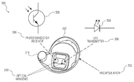
- FIG. 1 is a first example 100 of an optical communication interface.
- the first optical communication interface 100 includes: a handheld device 102 configured to communicate with a second device 104 .
- the handheld device 102 includes: an optical receiver 106 , an optical transmitter 108 (optional in some embodiments), an optical window 110 (optional in some embodiments), a wireless charge receiver 112 (optional in some embodiments), a processor 114 , data storage 116 , a power supply 118 (e.g. battery), an external surface 134 , an interior facing side 136 , and an exterior facing side 138 .
- an optical receiver 106 an optical transmitter 108 (optional in some embodiments), an optical window 110 (optional in some embodiments), a wireless charge receiver 112 (optional in some embodiments), a processor 114 , data storage 116 , a power supply 118 (e.g. battery), an external surface 134 , an interior facing side 136 , and an exterior facing side 138 .
- an optical receiver 106 includes: an optical receiver 106 , an optical transmitter 108 (optional in some embodiments), an optical window 110 (optional in some embodiments), a wireless charge receiver 112 (optional in some
- the second device 104 includes: an optical receiver 120 (optional in some embodiments), an optical transmitter 122 , an optical window 124 (optional in some embodiments), a wireless charge transmitter 126 (optional in some embodiments), a processor 128 , data storage 130 , a power supply 132 , an external surface 140 , an interior facing side 142 , and an exterior facing side 144 .
- the handheld device 102 has an external surface 134 having an interior facing side 136 and an exterior facing side 138 .
- the optical receiver 106 on the interior facing side 136 of the handheld device 102 , having an optical input and an electrical output.
- the electrical output is coupled to circuitry (e.g. processor 114 , data storage 116 , power supply 118 , etc.).
- the optical input is configured to be optically coupled (“dashed arrow”) to a second optical transmitter 122 on the exterior facing side 138 of the handheld device 102 .
- “On the exterior facing side 138 ” is herein defined to include the handheld device's 102 external environment, which may or may not actually be in physical contact with the handheld device 102 .
- the optical transmitter 108 on the interior facing side 136 of the handheld device 102 , also has an electrical input and an optical output. This electrical input is also coupled to the circuitry.
- the optical output is configured to be coupled (opposite facing “dashed arrow”) to a second optical receiver 120 on the exterior facing side 138 of the handheld device 102 .
- the second optical receiver 120 and the second optical transmitter 122 are coupled within the external surface 140 of the second device 104 .
- the first optical receiver 106 is configured to be separated from the optical transmitter 122 by an air gap, perhaps less than one meter in some example embodiments.
- the first example optical communication interface 100 uses light for contactless communication and data transfer.
- the data exchanged can include: firmware updates; software update; file transfers; configuration or user profile set-up or reconfiguration (e.g. voice command language profiles); media storage (e.g. playlists); and application (App) program updates.
- both the handheld device 102 and the second device 104 each have optical receivers 106 , 120 and optical transmitters 108 , 122 .
- the optical receivers 106 , 120 and transmitters 108 , 122 form two optical transmitter/receiver communication paths for simultaneously receiving and transmitting information.
- the optical transmitters 108 , 122 in different examples can be: a photodiode, or an LED diode.
- the optical receiver 106 , 120 in different examples can be: a phototransistor, a photoconductor, or a light sensor.
- the external surface 134 includes an optical window 110 configured to enable the optical coupling with the second optical transmitter 122 .
- the optical window 110 is transparent or translucent over a set of optical frequencies which either the optical receiver 106 or optical transmitter 108 are configured to operate.
- the optical window 110 can be fabricated out of: transparent plastic, glass, quartz, or any material that is optically transparent to the frequencies being used.
- an encapsulation covers or envelops the exterior facing side 138 of the handheld device 102 .
- the encapsulation can be selected to form: a water-resistant seal, a water-tight seal, a dust-resistant seal, or a hermetic seal. If the encapsulation covers the optical window 110 , the encapsulation can also be selected to enable the optical coupling with the second optical transmitter 122 .
- the handheld device 102 can include multiple sets of optical transmitters 108 , 122 and receivers 106 , 120 distributed at various spatial locations on the handheld device 102 configured to flexibly connect with the second device 104 .
- the handheld device 102 can be: a mobile device, a medical device, a wearable device, a hearable, an earbud, or a smartphone.
- the second device 104 can be: a docking device, a base-station, a charging case, a smartphone, a computer, or a display screen surface.
- the second device 104 can be a display screen and the optical transmitter 122 is comprised of pixels on the display screen.
- the optical transmitter 108 or the optical receiver 106 on the handheld device 102 can in certain example embodiments also be used for at least one of: health monitoring or visual display, provided their frequency spectrum of operation is adjusted.
- the power supply 118 e.g. a disposable battery in the handheld device 102 is wirelessly charged.
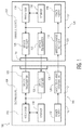
- FIG. 2 is a second example 200 of an optical communication interface.
- the second optical communication interface 200 includes a wearable 202 configured to communicate with a docking device 204 .
- the wearable 202 includes: an optical receiver 206 , an optical transmitter 208 , an optical window 210 , a wireless charge receiver 212 . a processor 214 , data storage 216 , and a power supply 218 .
- the docking device 204 includes: an optical receiver 220 , an optical transmitter 222 , an optical window 224 , a wireless charge transmitter 226 , a processor 228 , a USB interface 230 , data lines 232 , and a power input 234 .
- the docking device 204 (e.g. an earbud case) contains a processor 228 (e.g. microcontroller) with a High-Speed USB interface 230 .
- This MCU 228 buffers incoming USB communication data and enables the docking device 204 to convert the USB communication data to an optical UART (Universal Asynchronous Receiving and Transmitting), which is then transmitted to the wearable 202 (e.g. a hearable earbud).
- an optical UART Universal Asynchronous Receiving and Transmitting
- the wearable's 202 processor 214 e.g. MCU
- the wearable's 202 processor 214 is also used to receive and transmit data through the optical UART information interface.
- the second optical communication interface 200 e.g. SPI
- UART in some examples only requires 2 pins to establish bi-directional communications.
- the wearable 202 and docking device 204 are designed for an optimal (e.g. high signal to noise ratio) optical coupling between the wearable's 202 and the docking device's 204 optical receivers 206 , 220 and optical transmitter 208 , 222 by minimizing a distance (e.g. air gap) between, for example, a hearable 202 and is charging case 204 .
- an optimal optical coupling between the wearable's 202 and the docking device's 204 optical receivers 206 , 220 and optical transmitter 208 , 222 by minimizing a distance (e.g. air gap) between, for example, a hearable 202 and is charging case 204 .
- the wearable 202 and docking device 204 can include alignment elements configured to geometrically juxtapose each optical transmitter 208 , 222 and receiver 206 , 220 pair, thereby increasing their communications path signal-to-noise ratio.
- the alignment elements can include: a mechanical element; a magnetic element, or an electro-mechanical positioning element.
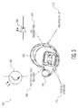
- FIG. 3 is a third example 300 of an optical communication interface.
- the third optical communication interface 300 is embedded in an example earbud 302 .
- the earbud 302 includes: an optical receiver 306 , an optical transmitter 308 , an optical windows 310 , encapsulation 312 , a speaker 314 , a wireless charge receiver (not shown), a processor (not shown), data storage (not shown), and a power supply (not shown).
- the third example 300 shows an example contactless hermetically sealed earbud using the encapsulation 312 .
- Encapsulation 312 increases a lifetime of the earbud 302 and simplifies construction.
- the encapsulation 312 is selected to minimize interference with the optical communications paths between the earbud 302 and its docking/charging case (not shown).
Landscapes
- Engineering & Computer Science (AREA)
- Physics & Mathematics (AREA)
- Signal Processing (AREA)
- Electromagnetism (AREA)
- Computer Networks & Wireless Communication (AREA)
- Acoustics & Sound (AREA)
- Microelectronics & Electronic Packaging (AREA)
- Optics & Photonics (AREA)
- Optical Communication System (AREA)
- Charge And Discharge Circuits For Batteries Or The Like (AREA)
Abstract
Description
- The present specification relates to systems, methods, apparatuses, devices, articles of manufacture and instructions for an optical communications interface.
- According to an example embodiment, an optical communication interface for a handheld device: wherein the handheld device, has an external surface; wherein the external surface includes an interior facing side and an exterior facing side; a first optical receiver, on the interior facing side of the handheld device, having an optical input and an electrical output; wherein the electrical output is coupled to circuitry; and wherein the optical input is configured to be optically coupled to a second optical transmitter on the exterior facing side of the handheld device.
- In another example embodiment, further comprising, a first optical transmitter, on the interior facing side of the handheld device, and having an electrical input and an optical output; wherein the electrical input is coupled to the circuitry; and wherein the optical output is configured to be coupled to a second optical receiver on the exterior facing side of the handheld device.
- In another example embodiment, the second optical receiver and the second optical transmitter are coupled within an external surface of a second device.
- In another example embodiment, the first optical receiver is configured to be separated from the second optical transmitter by an air gap less than one meter.
- In another example embodiment, the handheld device is at least one of: a mobile device, a medical device, a wearable device, a hearable, an earbud, or a smartphone.
- In another example embodiment, the second device is at least one of: a docking device, a base-station, a charging case, a smartphone, a computer, or a display screen surface.
- In another example embodiment, the optical transmitter in the second device is a display screen.
- In another example embodiment, the optical transmitter is at least one of: a photodiode, or an LED diode; and the optical receiver is at least one of: a phototransistor, a photoconductor, or a light sensor.
- In another example embodiment, the handheld device includes multiple sets of optical transmitters and receivers distributed at various spatial locations on the handheld device configured to flexibly connect with the second device.
- In another example embodiment, the handheld device and second device include alignment elements configured to increase a signal-to-noise ratio between at least one optical transmitter and receiver pair.
- In another example embodiment, the first optical transmitter and first optical receiver are configured to exchange data with the second device using optical wavelengths; and data exchanged includes at least one of: firmware updates; software update; file transfers; configuration or user profile set-up or reconfiguration (e.g. voice command language profiles); media storage (e.g. playlists); and application (App) program updates.
- In another example embodiment, the optical transmitter or the optical receiver on the handheld device are also used for at least one of: health monitoring or visual display.
- In another example embodiment, the external surface includes an optical window configured to enable the optical coupling with the second optical transmitter.
- In another example embodiment, the optical window is transparent or translucent over a set of optical frequencies which either the first optical receiver or first optical transmitter are configured to operate; and the optical window includes at least one of: transparent plastic, glass, quartz, or any material that is optically transparent to the frequencies being used.
- In another example embodiment, further comprising an encapsulation covering the exterior facing side of the handheld device.
- In another example embodiment, the encapsulation forms at least one of: a water-resistant seal, a water-tight seal, a dust-resistant seal, or a hermetic seal.
- In another example embodiment, the encapsulation is configured to enable the optical coupling with the second optical transmitter.
- According to an example embodiment, an optical communication interface for a handheld device: wherein the handheld device, has an external surface; wherein the external surface includes an interior facing side and an exterior facing side; a first optical transmitter, on the interior facing side of the handheld device, and having an electrical input and an optical output; wherein the electrical output is coupled to circuitry; and wherein the optical output is configured to be coupled to an optical receiver on the exterior facing side of the handheld device.
- According to an example embodiment, an optical communication interface for a contactless earbud: wherein the contactless earbud, has an external surface; wherein the external surface includes an interior facing side and an exterior facing side; a first optical receiver, on the interior facing side of the contactless earbud, having an optical input and an electrical output; herein the electrical output is coupled to circuitry; wherein the optical input is configured to be optically coupled to a second optical transmitter on the exterior facing side of the contactless earbud; a first optical transmitter, on the interior facing side of the contactless earbud, and having an electrical input and an optical output; wherein the electrical input is coupled to the circuitry; wherein the optical output is configured to be coupled to a second optical receiver on the exterior facing side of the contactless earbud.
- The above discussion is not intended to represent every example embodiment or every implementation within the scope of the current or future Claim sets. The Figures and Detailed Description that follow also exemplify various example embodiments.
- Various example embodiments may be more completely understood in consideration of the following Detailed Description in connection with the accompanying Drawings, in which:
-
FIG. 1 is a first example of an optical communication interface. -
FIG. 2 is a second example of an optical communication interface. -
FIG. 3 is a third example of an optical communication interface. - While the disclosure is amenable to various modifications and alternative forms, specifics thereof have been shown by way of example in the drawings and will be described in detail. It should be understood, however, that other embodiments, beyond the particular embodiments described, are possible as well. All modifications, equivalents, and alternative embodiments falling within the spirit and scope of the appended claims are covered as well.
- Handheld devices come in many forms such as: a smartphone, a wearable device, a hearable, an earbud, mobile devices and various medical devices. Handheld devices are herein defined to include devices that can be readily carried by an average person. Such handheld devices are not necessarily continually held in a person's hand, but in many example embodiments are at some point carried in a person's hand, such as when affixing to a piece of clothing, a fixture, or a person's body.
- Handheld devices, such as hearables for example, can consist of two wireless earbuds with embedded audio and sensor capabilities. In terms of audio capabilities, they can support in most cases playback of stereo audio from an external device such as a cellphone and making phone calls. They can communicate with the cellphone through Bluetooth Classic or through Bluetooth Low Energy (BLE).
- Some handheld devices may use a USB cable for charging their internal batteries and for data transfer. Such data-transfer may include: embedded firmware upgrades, updating of the embedded voice prompts (e.g. when the user selects a new language) and/or updating an embedded media (e.g. MP3) database.
- However, since other handheld devices (e.g. hearables, earbuds, etc.) are space-constrained, there is little to no room for a standard USB connector. One example approach is to construct a custom USB port/connector on the handheld device's docking station, which also includes a standard USB port.
- In one example, such a custom USB connector may include individual galvanic contacts with pogo-pins. Such custom USB connectors could transport both power and data in a manner similar to a standard USB port and cable.
- Example custom USB connectors however may have various problems. For example:
-
- the custom connector may be mechanically or electrically complicated and costly, with many mechanical design constraints;
- guaranteeing signal integrity (which is crucial for USB 3.0) across the connector may be difficult, leading to reduced data transfer speeds;
- the galvanic contacts may corrode or otherwise become damaged over time;
- extra electronic precautions may be required to ensure that the handheld device's battery does not discharge thru the custom connector when a person is wearing the devices (e.g. through conductive sweat perhaps); and
- galvanic contacts may compromise the water tightness of the handheld device.
- Contactless handheld devices may have problems of their own. For example, a standard/custom USB connector's high-speed data transfer capability is lost when going to some example contactless earbuds.
- Some handheld devices while including one or more of following radios for wireless data communication, may not have sufficient BW available for transferring large databases in a reasonable amount of time. For example:
-
- Bluetooth Classic:
- Maximum PHY rate is 3 Mbps in EDR mode;
- Actual data throughput may however be only a fraction of this;
- Bluetooth Low Energy:
- Maximum PHY rate today is 1 Mbps;
- A new PHY mode with maximum PHY rate of 2 Mbps is being standardized;
- Actual data throughput may however be only a fraction of this;
- NearField Magnetic Induction radio:
- Maximum PHY rate today is 0.6 Mbps;
- Actual data throughput may however be only a fraction of this.
- Bluetooth Classic:
- Wireless charging standards, such as Qi or A4WP, similarly only offer a very limited communication bandwidth, which is used for controlling the wireless charging behavior and not for application data transfer.
- Other means for contactless data transfer, such as adding an additional radio with sufficient data throughput, such as WiFi, UWB or other, have high power consumption, increase the cost of the handheld device, take up valuable internal device real estate, and require an additional antenna. This can make integration of an additional high-speed radio into such a space-constrained device unpractical.
- Discussed below is an optical means of achieving high-speed data transfer option for handheld devices, without requiring an additional transceiver or antenna.
-
FIG. 1 is a first example 100 of an optical communication interface. The firstoptical communication interface 100 includes: ahandheld device 102 configured to communicate with asecond device 104. - The
handheld device 102 includes: anoptical receiver 106, an optical transmitter 108 (optional in some embodiments), an optical window 110 (optional in some embodiments), a wireless charge receiver 112 (optional in some embodiments), aprocessor 114,data storage 116, a power supply 118 (e.g. battery), anexternal surface 134, aninterior facing side 136, and anexterior facing side 138. - The
second device 104 includes: an optical receiver 120 (optional in some embodiments), anoptical transmitter 122, an optical window 124 (optional in some embodiments), a wireless charge transmitter 126 (optional in some embodiments), aprocessor 128,data storage 130, apower supply 132, anexternal surface 140, aninterior facing side 142, and anexterior facing side 144. - The
handheld device 102, has anexternal surface 134 having an interior facingside 136 and anexterior facing side 138. Theoptical receiver 106, on theinterior facing side 136 of thehandheld device 102, having an optical input and an electrical output. The electrical output is coupled to circuitry (e.g. processor 114,data storage 116,power supply 118, etc.). - The optical input is configured to be optically coupled (“dashed arrow”) to a second
optical transmitter 122 on theexterior facing side 138 of thehandheld device 102. “On theexterior facing side 138” is herein defined to include the handheld device's 102 external environment, which may or may not actually be in physical contact with thehandheld device 102. - The
optical transmitter 108, on theinterior facing side 136 of thehandheld device 102, also has an electrical input and an optical output. This electrical input is also coupled to the circuitry. The optical output is configured to be coupled (opposite facing “dashed arrow”) to a secondoptical receiver 120 on theexterior facing side 138 of thehandheld device 102. - In one example, the second
optical receiver 120 and the secondoptical transmitter 122 are coupled within theexternal surface 140 of thesecond device 104. - The first
optical receiver 106 is configured to be separated from theoptical transmitter 122 by an air gap, perhaps less than one meter in some example embodiments. Thus the first exampleoptical communication interface 100 uses light for contactless communication and data transfer. - The data exchanged can include: firmware updates; software update; file transfers; configuration or user profile set-up or reconfiguration (e.g. voice command language profiles); media storage (e.g. playlists); and application (App) program updates.
- In one example, both the
handheld device 102 and thesecond device 104 each haveoptical receivers optical transmitters optical receivers transmitters - The
optical transmitters - Similarly, the
optical receiver - The
external surface 134 includes anoptical window 110 configured to enable the optical coupling with the secondoptical transmitter 122. Theoptical window 110 is transparent or translucent over a set of optical frequencies which either theoptical receiver 106 oroptical transmitter 108 are configured to operate. Theoptical window 110 can be fabricated out of: transparent plastic, glass, quartz, or any material that is optically transparent to the frequencies being used. - In some example embodiments, an encapsulation (see 312 in
FIG. 3 ) covers or envelops theexterior facing side 138 of thehandheld device 102. The encapsulation can be selected to form: a water-resistant seal, a water-tight seal, a dust-resistant seal, or a hermetic seal. If the encapsulation covers theoptical window 110, the encapsulation can also be selected to enable the optical coupling with the secondoptical transmitter 122. - In other example embodiments, the
handheld device 102 can include multiple sets ofoptical transmitters receivers handheld device 102 configured to flexibly connect with thesecond device 104. - In various example embodiments, the
handheld device 102 can be: a mobile device, a medical device, a wearable device, a hearable, an earbud, or a smartphone. - Similarly, in various example embodiments, the
second device 104 can be: a docking device, a base-station, a charging case, a smartphone, a computer, or a display screen surface. - If only one way data transfer is required, the
second device 104 can be a display screen and theoptical transmitter 122 is comprised of pixels on the display screen. - The
optical transmitter 108 or theoptical receiver 106 on thehandheld device 102 can in certain example embodiments also be used for at least one of: health monitoring or visual display, provided their frequency spectrum of operation is adjusted. - In certain example embodiments, the power supply 118 (e.g. a disposable battery) in the
handheld device 102 is wirelessly charged. -
FIG. 2 is a second example 200 of an optical communication interface. The secondoptical communication interface 200 includes a wearable 202 configured to communicate with adocking device 204. - The wearable 202 includes: an
optical receiver 206, anoptical transmitter 208, anoptical window 210, awireless charge receiver 212. aprocessor 214,data storage 216, and apower supply 218. - The
docking device 204 includes: anoptical receiver 220, anoptical transmitter 222, anoptical window 224, awireless charge transmitter 226, aprocessor 228, aUSB interface 230,data lines 232, and apower input 234. - In this second example 200, the docking device 204 (e.g. an earbud case) contains a processor 228 (e.g. microcontroller) with a High-
Speed USB interface 230. ThisMCU 228 buffers incoming USB communication data and enables thedocking device 204 to convert the USB communication data to an optical UART (Universal Asynchronous Receiving and Transmitting), which is then transmitted to the wearable 202 (e.g. a hearable earbud). - Conversely, the wearable's 202 processor 214 (e.g. MCU) is also used to receive and transmit data through the optical UART information interface. Although other communication protocols could be used for the second optical communication interface 200 (e.g. SPI), UART in some examples only requires 2 pins to establish bi-directional communications.
- In certain example embodiments, the wearable 202 and
docking device 204 are designed for an optimal (e.g. high signal to noise ratio) optical coupling between the wearable's 202 and the docking device's 204optical receivers optical transmitter case 204. - Additionally, the wearable 202 and
docking device 204 can include alignment elements configured to geometrically juxtapose eachoptical transmitter receiver - The alignment elements can include: a mechanical element; a magnetic element, or an electro-mechanical positioning element.
-
FIG. 3 is a third example 300 of an optical communication interface. The thirdoptical communication interface 300 is embedded in anexample earbud 302. - The
earbud 302 includes: anoptical receiver 306, anoptical transmitter 308, anoptical windows 310,encapsulation 312, aspeaker 314, a wireless charge receiver (not shown), a processor (not shown), data storage (not shown), and a power supply (not shown). - The third example 300 shows an example contactless hermetically sealed earbud using the
encapsulation 312.Encapsulation 312 increases a lifetime of theearbud 302 and simplifies construction. Theencapsulation 312 is selected to minimize interference with the optical communications paths between theearbud 302 and its docking/charging case (not shown). - In this specification, example embodiments have been presented in terms of a selected set of details. However, a person of ordinary skill in the art would understand that many other example embodiments may be practiced which include a different selected set of these details. It is intended that the following claims cover all possible example embodiments.
Claims (19)
Priority Applications (3)
| Application Number | Priority Date | Filing Date | Title |
|---|---|---|---|
| US15/285,243 US10057672B2 (en) | 2016-10-04 | 2016-10-04 | Optical communication interface |
| EP17192471.5A EP3306833B1 (en) | 2016-10-04 | 2017-09-21 | Optical communication interface |
| CN201710889423.7A CN107895854B (en) | 2016-10-04 | 2017-09-27 | Optical communication interface |
Applications Claiming Priority (1)
| Application Number | Priority Date | Filing Date | Title |
|---|---|---|---|
| US15/285,243 US10057672B2 (en) | 2016-10-04 | 2016-10-04 | Optical communication interface |
Publications (2)
| Publication Number | Publication Date |
|---|---|
| US20180098144A1 true US20180098144A1 (en) | 2018-04-05 |
| US10057672B2 US10057672B2 (en) | 2018-08-21 |
Family
ID=60119774
Family Applications (1)
| Application Number | Title | Priority Date | Filing Date |
|---|---|---|---|
| US15/285,243 Active US10057672B2 (en) | 2016-10-04 | 2016-10-04 | Optical communication interface |
Country Status (3)
| Country | Link |
|---|---|
| US (1) | US10057672B2 (en) |
| EP (1) | EP3306833B1 (en) |
| CN (1) | CN107895854B (en) |
Cited By (3)
| Publication number | Priority date | Publication date | Assignee | Title |
|---|---|---|---|---|
| WO2020149707A1 (en) * | 2019-01-18 | 2020-07-23 | 아이알트로닉스 인코퍼레이티드 | Sound output device |
| WO2023120921A1 (en) * | 2021-12-24 | 2023-06-29 | 삼성전자주식회사 | Firmware update method, electronic device performing same, and charging device |
| US20240200770A1 (en) * | 2022-12-16 | 2024-06-20 | Guoguang Electric Company Limited | Light guide structure of earphone charging case |
Families Citing this family (4)
| Publication number | Priority date | Publication date | Assignee | Title |
|---|---|---|---|---|
| CN108712210A (en) * | 2018-05-28 | 2018-10-26 | 许谐兴 | A kind of single sharing method of intelligence song and its system based on LIFI communications |
| CN108600892B (en) * | 2018-06-15 | 2020-05-22 | 歌尔科技有限公司 | Upgrading method and device, wireless headset, TWS headset and charging box |
| CN109150294B (en) * | 2018-08-14 | 2021-02-23 | 歌尔科技有限公司 | Communication method, wireless earphone and charging box |
| CN111432302A (en) * | 2020-03-19 | 2020-07-17 | 歌尔科技有限公司 | Headset system, headset and peripheral equipment |
Citations (19)
| Publication number | Priority date | Publication date | Assignee | Title |
|---|---|---|---|---|
| US5887063A (en) * | 1995-07-28 | 1999-03-23 | Hewlett-Packard Company | Communication system for portable appliances |
| US20060094936A1 (en) * | 2004-10-29 | 2006-05-04 | Tomas Russ | Automatic wireless PAN/LAN switching |
| US20060256070A1 (en) * | 2005-05-13 | 2006-11-16 | Research In Motion Limited | Communications system including units with LCD optical transmitters/receivers and related methods |
| US7848405B2 (en) * | 2006-08-04 | 2010-12-07 | Hitachi Kokusai Electric, Inc. | Communication system |
| US8139943B2 (en) * | 2007-01-19 | 2012-03-20 | Sony Corporation | Optical communication apparatus and optical communication method |
| US8600236B2 (en) * | 2008-07-16 | 2013-12-03 | Opticis. Co., Ltd. | Optical communication module for optical wavelength division multiplexing |
| US20140029494A1 (en) * | 2012-07-27 | 2014-01-30 | Motorola Solutions, Inc. | Power saving for a mobile device in a wireless communication network |
| US20140160880A1 (en) * | 2012-12-10 | 2014-06-12 | Apple Inc. | Ultrasound ranging for mobile devices |
| US9020352B2 (en) * | 2010-11-18 | 2015-04-28 | Opticis Co., Ltd. | Optical communication module |
| US20150141752A1 (en) * | 2012-05-19 | 2015-05-21 | Capso Vision, Inc. | Optical Wireless Docking System for Capsule Camera |
| US20160142156A1 (en) * | 2014-11-18 | 2016-05-19 | Qualcomm Incorporated | Integrated device package and/or system comprising configurable directional optical transmitter |
| US20160329961A1 (en) * | 2014-01-30 | 2016-11-10 | Nokia Technologies Oy | Free-space optical communications for mobile devices |
| US9584074B2 (en) * | 2008-02-13 | 2017-02-28 | Arris Enterprises, Inc. | Optical receiver with automatic distortion cancellation |
| US9654225B2 (en) * | 2015-09-18 | 2017-05-16 | Elenion Technologies, Llc | Optical link architecture based on wireline equalization techniques |
| US9794002B1 (en) * | 2016-03-22 | 2017-10-17 | Dell Products, Lp | Integrated multiplexed RF-to-optical interconnect for portable electronic devices |
| US9823361B2 (en) * | 2012-07-24 | 2017-11-21 | Canon Kabushiki Kaisha | Radiation imaging control apparatus, radiation imaging system and radiation imaging apparatus, and method for controlling the same |
| US9866321B2 (en) * | 2014-05-02 | 2018-01-09 | Hakseo OH | Data transmission system for automated material handling system |
| US9921794B2 (en) * | 2015-07-29 | 2018-03-20 | Samsung Display Co., Ltd. | Blind display device |
| US9941990B2 (en) * | 2013-10-15 | 2018-04-10 | Elenion Technologies, Llc | Operation and stabilization of Mod-MUX WDM transmitters based on silicon microrings |
Family Cites Families (29)
| Publication number | Priority date | Publication date | Assignee | Title |
|---|---|---|---|---|
| IT1159851B (en) * | 1978-06-20 | 1987-03-04 | Cselt Centro Studi Lab Telecom | IMPROVEMENTS IN WAVE LENGTH DIVISION TRANSMISSION SYSTEMS |
| JPS60160231A (en) * | 1984-01-31 | 1985-08-21 | Toshiba Corp | Loop form optical dataway system |
| JP3641983B2 (en) * | 1998-11-10 | 2005-04-27 | 日産自動車株式会社 | Mobile phone holding device |
| WO2001086621A1 (en) * | 2000-05-09 | 2001-11-15 | John Edwin Mccloud | Portable electronic device with rear-facing touch typing keyboard |
| RU2178954C1 (en) | 2001-03-01 | 2002-01-27 | Септре Коммуникейшинс Лимитед | Optical wireless duplex communication system |
| US20030054784A1 (en) * | 2001-09-18 | 2003-03-20 | Conklin Fredrick C. | Infrared full-duplex wireless communication device |
| US7970030B2 (en) * | 2004-07-27 | 2011-06-28 | Biolase Technology, Inc. | Dual pulse-width medical laser with presets |
| US20080166006A1 (en) | 2007-01-06 | 2008-07-10 | Apple Inc | Light diffuser |
| US8180078B2 (en) * | 2007-12-13 | 2012-05-15 | At&T Intellectual Property I, Lp | Systems and methods employing multiple individual wireless earbuds for a common audio source |
| US8321228B2 (en) * | 2009-08-26 | 2012-11-27 | Nokia Corporation | Audio interface unit for supporting network services |
| US20110110534A1 (en) * | 2009-11-12 | 2011-05-12 | Apple Inc. | Adjustable voice output based on device status |
| US20110161085A1 (en) * | 2009-12-31 | 2011-06-30 | Nokia Corporation | Method and apparatus for audio summary of activity for user |
| US8577190B2 (en) | 2010-03-23 | 2013-11-05 | Avago Technologies General Ip (Singapore) Pte. Ltd. | Optocoupler |
| US20140016796A1 (en) * | 2012-07-10 | 2014-01-16 | Ann L. Maust | Portable wireless earphone system |
| US20140219467A1 (en) * | 2013-02-07 | 2014-08-07 | Earmonics, Llc | Media playback system having wireless earbuds |
| US9210493B2 (en) * | 2013-03-14 | 2015-12-08 | Cirrus Logic, Inc. | Wireless earpiece with local audio cache |
| JP6184776B2 (en) | 2013-07-04 | 2017-08-23 | ローム株式会社 | Visible light communication system |
| US20150148632A1 (en) * | 2013-11-26 | 2015-05-28 | David Alan Benaron | Calorie Monitoring Sensor And Method For Cell Phones, Smart Watches, Occupancy Sensors, And Wearables |
| US10171643B2 (en) * | 2014-01-22 | 2019-01-01 | Sony Corporation | Directing audio output based on gestures |
| US9525936B1 (en) * | 2014-02-05 | 2016-12-20 | Google Inc. | Wireless earbud communications using magnetic induction |
| US9485561B2 (en) * | 2014-08-14 | 2016-11-01 | Logitech Europe S.A. | Thermal powered wearable device |
| US20160182991A1 (en) * | 2014-09-07 | 2016-06-23 | Joseph John Zakzeski | Wireless earbuds without separate audio source |
| US9947215B2 (en) * | 2014-09-26 | 2018-04-17 | Harman International Industries, Incorporated | Pedestrian information system |
| WO2016111993A1 (en) * | 2015-01-05 | 2016-07-14 | Skullcandy, Inc. | Human performance optimization and training methods and systems |
| US9924270B2 (en) * | 2015-01-09 | 2018-03-20 | Intel Corporation | Techniques for channelization of stereo audio in headphones |
| US9438300B1 (en) * | 2015-03-10 | 2016-09-06 | Invensense, Inc. | Sensor fusion for antenna tuning |
| US20170064830A1 (en) * | 2015-08-24 | 2017-03-02 | Motorola Mobility Llc | Circuit Assembly for Compact Acoustic Device |
| EP3541092B1 (en) * | 2015-09-30 | 2021-08-11 | Apple Inc. | Earbud case with charging system |
| US9774941B2 (en) * | 2016-01-19 | 2017-09-26 | Apple Inc. | In-ear speaker hybrid audio transparency system |
-
2016
- 2016-10-04 US US15/285,243 patent/US10057672B2/en active Active
-
2017
- 2017-09-21 EP EP17192471.5A patent/EP3306833B1/en active Active
- 2017-09-27 CN CN201710889423.7A patent/CN107895854B/en active Active
Patent Citations (20)
| Publication number | Priority date | Publication date | Assignee | Title |
|---|---|---|---|---|
| US5887063A (en) * | 1995-07-28 | 1999-03-23 | Hewlett-Packard Company | Communication system for portable appliances |
| US20060094936A1 (en) * | 2004-10-29 | 2006-05-04 | Tomas Russ | Automatic wireless PAN/LAN switching |
| US20060256070A1 (en) * | 2005-05-13 | 2006-11-16 | Research In Motion Limited | Communications system including units with LCD optical transmitters/receivers and related methods |
| US7848405B2 (en) * | 2006-08-04 | 2010-12-07 | Hitachi Kokusai Electric, Inc. | Communication system |
| US8139943B2 (en) * | 2007-01-19 | 2012-03-20 | Sony Corporation | Optical communication apparatus and optical communication method |
| US9584074B2 (en) * | 2008-02-13 | 2017-02-28 | Arris Enterprises, Inc. | Optical receiver with automatic distortion cancellation |
| US8600236B2 (en) * | 2008-07-16 | 2013-12-03 | Opticis. Co., Ltd. | Optical communication module for optical wavelength division multiplexing |
| US9020352B2 (en) * | 2010-11-18 | 2015-04-28 | Opticis Co., Ltd. | Optical communication module |
| US20150141752A1 (en) * | 2012-05-19 | 2015-05-21 | Capso Vision, Inc. | Optical Wireless Docking System for Capsule Camera |
| US9823361B2 (en) * | 2012-07-24 | 2017-11-21 | Canon Kabushiki Kaisha | Radiation imaging control apparatus, radiation imaging system and radiation imaging apparatus, and method for controlling the same |
| US20140029494A1 (en) * | 2012-07-27 | 2014-01-30 | Motorola Solutions, Inc. | Power saving for a mobile device in a wireless communication network |
| US20140160880A1 (en) * | 2012-12-10 | 2014-06-12 | Apple Inc. | Ultrasound ranging for mobile devices |
| US9941990B2 (en) * | 2013-10-15 | 2018-04-10 | Elenion Technologies, Llc | Operation and stabilization of Mod-MUX WDM transmitters based on silicon microrings |
| US20160329961A1 (en) * | 2014-01-30 | 2016-11-10 | Nokia Technologies Oy | Free-space optical communications for mobile devices |
| US9866321B2 (en) * | 2014-05-02 | 2018-01-09 | Hakseo OH | Data transmission system for automated material handling system |
| US20160142156A1 (en) * | 2014-11-18 | 2016-05-19 | Qualcomm Incorporated | Integrated device package and/or system comprising configurable directional optical transmitter |
| US9921794B2 (en) * | 2015-07-29 | 2018-03-20 | Samsung Display Co., Ltd. | Blind display device |
| US9654225B2 (en) * | 2015-09-18 | 2017-05-16 | Elenion Technologies, Llc | Optical link architecture based on wireline equalization techniques |
| US9941976B2 (en) * | 2015-09-18 | 2018-04-10 | Elenion Technologies, Llc | Optical link architecture based on wireline equalization techniques |
| US9794002B1 (en) * | 2016-03-22 | 2017-10-17 | Dell Products, Lp | Integrated multiplexed RF-to-optical interconnect for portable electronic devices |
Cited By (5)
| Publication number | Priority date | Publication date | Assignee | Title |
|---|---|---|---|---|
| WO2020149707A1 (en) * | 2019-01-18 | 2020-07-23 | 아이알트로닉스 인코퍼레이티드 | Sound output device |
| US11882392B2 (en) | 2019-01-18 | 2024-01-23 | Irtronix, Inc. | Sound output device |
| WO2023120921A1 (en) * | 2021-12-24 | 2023-06-29 | 삼성전자주식회사 | Firmware update method, electronic device performing same, and charging device |
| US20240200770A1 (en) * | 2022-12-16 | 2024-06-20 | Guoguang Electric Company Limited | Light guide structure of earphone charging case |
| US12104780B2 (en) * | 2022-12-16 | 2024-10-01 | Guoguang Electric Company Limited | Light guide structure of earphone charging case |
Also Published As
| Publication number | Publication date |
|---|---|
| CN107895854B (en) | 2021-09-03 |
| EP3306833A1 (en) | 2018-04-11 |
| US10057672B2 (en) | 2018-08-21 |
| CN107895854A (en) | 2018-04-10 |
| EP3306833B1 (en) | 2020-11-18 |
Similar Documents
| Publication | Publication Date | Title |
|---|---|---|
| US10057672B2 (en) | Optical communication interface | |
| US12537385B2 (en) | Smart ring power and charging | |
| US20190007763A1 (en) | Wireless Earphone | |
| US10020668B2 (en) | Charging apparatus for wearable electronic device | |
| US20170257692A1 (en) | Low-loss wireless stereo Bluetooth earphones | |
| US12292728B2 (en) | Soft smart ring and method of manufacture | |
| US11564420B2 (en) | Wearable apparatus for wired or wireless charging of an electronic device | |
| CN103248978A (en) | Wireless adapter and wireless earphone | |
| CN106797144B (en) | Wireless Power Transmitter/Receiver Equipment | |
| CN104981029A (en) | Wireless self-organizing network audio and video communication system | |
| CN104281045B (en) | Solar energy intelligent watch combinative structure | |
| CN110417950B (en) | A mobile terminal | |
| CN110246312A (en) | One kind is convenient for deployment remote security early warning linked system | |
| CN216491087U (en) | A wireless base station structure | |
| CN204928202U (en) | Panel PC | |
| CN205596355U (en) | Portable wireless data chain terminal | |
| CN205566660U (en) | A data link equipment for relaying formula teletransmission | |
| US20260104734A1 (en) | Smart ring clip and method of manufacture | |
| CN203301707U (en) | 2.4G independent receiving type wireless headphone | |
| CN205283765U (en) | Earphone is received to visible light | |
| CN115857306A (en) | A wearable device combined with earphones and watches | |
| CN119603384A (en) | Visible light communication mobile phone | |
| WO2026056039A1 (en) | Smart ring | |
| WO2019206114A1 (en) | Mobile terminal and mobile phone | |
| WO2019206127A1 (en) | Mobile terminal and cellphone |
Legal Events
| Date | Code | Title | Description |
|---|---|---|---|
| AS | Assignment |
Owner name: NXP B.V., NETHERLANDS Free format text: ASSIGNMENT OF ASSIGNORS INTEREST;ASSIGNOR:THOEN, STEVEN MARK;REEL/FRAME:039935/0954 Effective date: 20161004 |
|
| STCF | Information on status: patent grant |
Free format text: PATENTED CASE |
|
| MAFP | Maintenance fee payment |
Free format text: PAYMENT OF MAINTENANCE FEE, 4TH YEAR, LARGE ENTITY (ORIGINAL EVENT CODE: M1551); ENTITY STATUS OF PATENT OWNER: LARGE ENTITY Year of fee payment: 4 |
|
| MAFP | Maintenance fee payment |
Free format text: PAYMENT OF MAINTENANCE FEE, 8TH YEAR, LARGE ENTITY (ORIGINAL EVENT CODE: M1552); ENTITY STATUS OF PATENT OWNER: LARGE ENTITY Year of fee payment: 8 |