US20180098135A1 - A device-frame for telecommunication devices - Google Patents
A device-frame for telecommunication devices Download PDFInfo
- Publication number
- US20180098135A1 US20180098135A1 US15/565,946 US201515565946A US2018098135A1 US 20180098135 A1 US20180098135 A1 US 20180098135A1 US 201515565946 A US201515565946 A US 201515565946A US 2018098135 A1 US2018098135 A1 US 2018098135A1
- Authority
- US
- United States
- Prior art keywords
- frame
- air
- guide element
- section
- telecommunication devices
- Prior art date
- Legal status (The legal status is an assumption and is not a legal conclusion. Google has not performed a legal analysis and makes no representation as to the accuracy of the status listed.)
- Granted
Links
Images
Classifications
-
- H—ELECTRICITY
- H04—ELECTRIC COMMUNICATION TECHNIQUE
- H04Q—SELECTING
- H04Q1/00—Details of selecting apparatus or arrangements
- H04Q1/02—Constructional details
- H04Q1/035—Cooling of active equipments, e.g. air ducts
-
- H—ELECTRICITY
- H04—ELECTRIC COMMUNICATION TECHNIQUE
- H04Q—SELECTING
- H04Q1/00—Details of selecting apparatus or arrangements
- H04Q1/02—Constructional details
- H04Q1/04—Frames or mounting racks for selector switches; Accessories therefor, e.g. frame cover
-
- H—ELECTRICITY
- H04—ELECTRIC COMMUNICATION TECHNIQUE
- H04Q—SELECTING
- H04Q1/00—Details of selecting apparatus or arrangements
- H04Q1/02—Constructional details
- H04Q1/09—Frames or mounting racks not otherwise provided for
Definitions
- the disclosure relates generally to telecommunication equipment where telecommunication devices are placed in plug-in unit places of device-frames that are installed in a rack. Furthermore, the disclosure relates to a device-frame for telecommunication devices.
- telecommunication equipment is modular so that the telecommunication equipment comprises a rack and telecommunication devices are installed directly or with the aid of device-frames in the rack.
- telecommunication includes also “data communication” and other data and message transfer technologies.
- the above-mentioned telecommunication devices may constitute, for example but not necessarily, one or more internet protocol “IP” routers, one or more Ethernet switches, one or more Asynchronous Transfer Mode “ATM” switches, one or more MultiProtocol Label Switching “MPLS” switches, and/or one or more packet optical switches.
- IP internet protocol
- ATM Asynchronous Transfer Mode
- MPLS MultiProtocol Label Switching
- a rack of modular telecommunication equipment may comprise for example mutually parallel rails that are substantially vertical when the rack is in its operating position.
- the telecommunication devices of the telecommunication equipment can be for example plug-in units that are installed in plug-in unit places of one or more device-frames that are, in turn, attached to the vertical rails of the rack.
- the lower part of each device-frame comprises an air-intake for receiving cooling air and the upper part of the device-frame comprises an air-outlet through which the cooling air can leave the device-frame.
- the cooling air transfers heat from the plug-in units that are installed in the plug-in unit places of the device-frame under consideration.
- the device-frame further comprises a blower for moving the cooling air through the device-frame.
- the device-frame may comprise a filter for filtering the cooling air prior to the cooling air meets the plug-in units.
- a new device-frame for telecommunication devices may constitute, for example but not necessarily, one or more internet protocol “IP” routers, one or more Ethernet switches, one or more Asynchronous Transfer Mode “ATM” switches, one or more MultiProtocol Label Switching “MPLS” switches, and/or one or more packet optical switches.
- IP internet protocol
- ATM Asynchronous Transfer Mode
- MPLS MultiProtocol Label Switching
- a device-frame according to the invention comprises:
- the height of the device-frame can be adjusted to be smaller in a case where the circumstances are not the most demanding from the viewpoint of the cooling and therefore, in less demanding circumstances, it is possible that there can be more device-frames in a rack of telecommunication equipment.
- FIG. 1 a shows a perspective view of telecommunication equipment according to an exemplifying and non-limiting embodiment of the invention
- FIGS. 1 b and 1 c show a side view of one of the device-frames of the telecommunication equipment shown in FIG. 1 a.
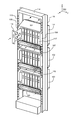
- FIG. 1 a shows a perspective view of telecommunication equipment according to an exemplifying and non-limiting embodiment of the invention.
- the telecommunication equipment comprises a rack 114 and device-frames 101 , 102 , and 103 installed in the rack.
- the rack comprises mutually parallel rails 115 and 116 that are substantially vertical when the rack 114 is in its operating position.
- Each of the device-frames 101 - 103 comprises a body-section that comprises plug-in unit places, i.e. plug-in unit slots, for telecommunication devices.
- Each of the device-frames 101 - 103 comprises mechanical structures for connecting the device-frame to the rack 114 .
- FIG. 1 a shows a perspective view of telecommunication equipment according to an exemplifying and non-limiting embodiment of the invention.
- the telecommunication equipment comprises a rack 114 and device-frames 101 , 102 , and 103 installed in the rack.
- the rack comprises mutually parallel rails 115 and 116 that are
- the mechanical structures are flanges with the aid of which the device-frame under consideration can be attached to the rails 115 and 116 of the rack as illustrated in FIG. 1 a.
- the body-section of the device-frame 101 is denoted with a reference number 104 and the above-mentioned mechanical structures, i.e. the flanges, of the device-frame 101 are denoted with reference numbers 105 and 106 .
- the rack could comprise for example horizontal beams on which the device-frames can be placed.
- the above-mentioned telecommunication devices are plug-in units that can be installed in the plug-in unit places of the device-frames 101 - 103 .
- two of the telecommunication devices are denoted with reference numbers 117 and 118 .
- the front section of each device-frame allows the telecommunication devices to be inserted in the device-frame under consideration.
- FIG. 1 a illustrates insertion of the telecommunication device 118 in the device-frame 101 .
- the telecommunication devices may constitute, for example but not necessarily, one or more internet protocol “IP” routers, one or more Ethernet switches, one or more Asynchronous Transfer Mode “ATM” switches, one or more MultiProtocol Label Switching “MPLS” switches, and/or one or more packet optical switches.
- IP internet protocol
- ATM Asynchronous Transfer Mode
- MPLS MultiProtocol Label Switching
- Each of the device-frames 101 - 103 comprises an air-guide element movably supported to the body-section of the device-frame.
- the flow area of an air-intake of the device-frame is increasable by changing the position of the air-guide element with respect to the body-section so that the height of the device-frame increases.
- the flow area is decreasable by changing the position of the air-guide element with respect to the body-section so that the height of the device-frame decreases.
- the heights of the device-frames are measured in the z-direction of a coordinate system 199 .
- the adjustable air-guide elements of the device-frames 101 - 103 are denoted with reference numbers 107 , 119 , and 120 .
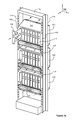
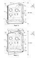
- FIGS. 1 b and 1 c show a side view of the device-frame 101 .
- FIGS. 1 a and 1 b show the telecommunication device 117 so that the part of the telecommunication device 117 that is inside the device-frame 101 is depicted with dashed lines.
- the viewing directions related to FIGS. 1 a -1 c are illustrated with the coordinate system 199 .
- FIG. 1 b illustrates an exemplifying situation where the air-guide element 107 is in a position where the flow area of the air-intake and the height H of the device-frame 101 are minimized, whereas FIG.
- FIGS. 1 a - 1 c illustrates an exemplifying situation where the air-guide element 107 is in another position where the flow area of the air-intake and the height H of the device frame 101 are greater.
- the flow of the cooling air is depicted with dashed line arrows.
- the adjustable air-guide elements 107 , 119 , and 120 of the device-frames 101 - 103 make it possible to change the intakes of the cooling air in accordance with case-specific needs.
- the air intake of a device-frame that is higher in the rack can be set to be greater than that of another device-frame that is lower in the rack.
- FIG. 1 a shows an exemplifying case where the air-guide element 107 of the upmost device-frame 101 is most open, the air-guide element 120 of the undermost device-frame 103 is least open, and the position of air-guide element 119 of the device-frame 102 is between the positions of the air-guide elements 107 and 120 .
- the movability of the air-guide elements 107 , 119 , and 120 makes it easier to install a cabling between the device-frames 101 - 103 and cables from/to the device frames to/from elsewhere in an equipment room.
- the cables from/to the device-frames to/from elsewhere in the equipment room are advantageously drawn via an upper part of the rack 114 so that the cables can be on shelves or on other support means near the ceiling of the equipment room and thus the operating persons do not have to watch out the cables.
- the adjustable air-guide elements do not complicate the transportation of the device-frames because each air-guide element can be positioned as illustrated in FIG. 1 b during transportation of the device-frame under consideration.
- a corollary e.g.
- a transportation box can be dimensioned according to the smallest height Hmin corresponding to the situation shown in FIG. 1 b.
- every device-frame comprises an adjustable air-guide element.
- telecommunication equipment according to another exemplifying embodiment of the invention comprises one or more device-frames each provided with an adjustable air-guide element and, in addition, one or more device-frames that do not comprise an adjustable air-guide element.
- the air-guide element 107 is hinged to the body-section 104 so that the flow area of the air-intake of the device-frame 101 is increasable by turning the air-guide element with respect to the body-section so that the height H of the device-frame increases and, correspondingly, the flow area is decreasable by turning the air-guide element with respect to the body-section so that the height of the device-frame decreases.
- the turning axis 108 of the hinged air-guide element 107 is substantially perpendicular to the height H of the device-frame and substantially parallel with the width of the device-frame.
- the width the device-frame is measured in the y-direction of the coordinate system 199 . Therefore, the turning axis 108 of the hinged air-guide element 107 is substantially parallel with the y-axis of the coordinate system 199 .
- the plug-in unit places are side-by-side in the direction of the width, i.e. in the lateral direction, of the device-frame.
- the turning axis 108 of the air-guide element is located at a portion of the device-frame 101 that is the lower portion of the rear section of the device-frame when the device-frame is in its operating position.
- the rear section is on the opposite side of the device-frame with respect to the front section through which the telecommunication devices can be inserted in the device-frame. It is, however, also possible that an air-guide element is movably supported to the body-section of a device-frame with other means than being hinged. For example, instead of being hinged, an air-guide element can be movably supported to the body-section with sliding means.
- a portion of the device-frame that is an upper portion of the device-frame when the device-frame is in its operating position is oblique so that a shape of the upper portion of the device-frame fits to a hinged air-guide element of another device-frame in a situation in which the other device-frame is above the first mentioned device-frame and the hinged air-guide element of the other device-frame has been turned downwards.
- the oblique upper portion of the device-frame is denoted with a reference number 109 .
- 1 c illustrates how the shape of the upper portion 109 of the device-frame 101 fits to the hinged air-guide element 121 of another device-frame 122 .
- the oblique upper portion 109 reduces a vertical distance needed between the body-sections of the device-frames 101 and 122 .
- the one or more blowers 110 is/are depicted with dashed lines because the one or more blowers is/are inside the body-section 104 of the device-frame 101 .
- the one or more blowers 110 is/are at the air-outlet through which the cooling air leaves the device-frame 101 but it is also possible that there is/are one or more blowers at the air-intake for receiving the cooling air.
- a device-frame comprises a filter 111 for filtering the cooling air arriving at the device-frame.
- the part 111 a of the filter 111 that is inside the body-section 104 of the device-frame 101 is depicted with dashed lines.
- the part 111 a of the filter is needed for filtering the portion of the incoming cooling air that passes, as shown in FIG. 1 c, the front part of the filter.
- the filter 111 may comprise for example filter paper and/or filter fabric and a filter frame for supporting the filter paper and/or the filter fabric.
- a device-frame comprises a back-plane 112 that comprises electrical connectors for connecting to the telecommunication devices and wirings for communicatively interconnecting the telecommunication devices.
- the back-plane 112 and one of the electrical connectors are depicted with dashed lines.
- the one of the electrical connectors is denoted with a reference number 113 .
Landscapes
- Engineering & Computer Science (AREA)
- Computer Networks & Wireless Communication (AREA)
- Cooling Or The Like Of Electrical Apparatus (AREA)
- Structure Of Telephone Exchanges (AREA)
Abstract
Description
- The disclosure relates generally to telecommunication equipment where telecommunication devices are placed in plug-in unit places of device-frames that are installed in a rack. Furthermore, the disclosure relates to a device-frame for telecommunication devices.
- In many cases it is advantageous that telecommunication equipment is modular so that the telecommunication equipment comprises a rack and telecommunication devices are installed directly or with the aid of device-frames in the rack. In this document, the term “telecommunication” includes also “data communication” and other data and message transfer technologies. The above-mentioned telecommunication devices may constitute, for example but not necessarily, one or more internet protocol “IP” routers, one or more Ethernet switches, one or more Asynchronous Transfer Mode “ATM” switches, one or more MultiProtocol Label Switching “MPLS” switches, and/or one or more packet optical switches.
- A rack of modular telecommunication equipment may comprise for example mutually parallel rails that are substantially vertical when the rack is in its operating position. The telecommunication devices of the telecommunication equipment can be for example plug-in units that are installed in plug-in unit places of one or more device-frames that are, in turn, attached to the vertical rails of the rack. In many cases, the lower part of each device-frame comprises an air-intake for receiving cooling air and the upper part of the device-frame comprises an air-outlet through which the cooling air can leave the device-frame. When the cooling air flows from the air-intake to the air-outlet, the cooling air transfers heat from the plug-in units that are installed in the plug-in unit places of the device-frame under consideration. In many cases, the device-frame further comprises a blower for moving the cooling air through the device-frame. Furthermore, the device-frame may comprise a filter for filtering the cooling air prior to the cooling air meets the plug-in units.
- An inherent inconvenience related to device-frames of the kind described above is that the cooling arrangement has to be designed according to the most demanding circumstances. Thus, for example the above-mentioned air-intake that has been designed according to the most demanding circumstances may require unnecessarily much room in the vertical direction in less demanding circumstances. The space requirement in the vertical direction is critical because, in many cases, it determines the number of device-frames that can be installed in a rack.
- The following presents a simplified summary in order to provide a basic understanding of some aspects of various invention embodiments. The summary is not an extensive overview of the invention. It is neither intended to identify key or critical elements of the invention nor to delineate the scope of the invention. The following summary merely presents some concepts of the invention in a simplified form as a prelude to a more detailed description of exemplifying embodiments of the invention.
- In accordance with the invention, there is provided a new device-frame for telecommunication devices that may constitute, for example but not necessarily, one or more internet protocol “IP” routers, one or more Ethernet switches, one or more Asynchronous Transfer Mode “ATM” switches, one or more MultiProtocol Label Switching “MPLS” switches, and/or one or more packet optical switches.
- A device-frame according to the invention comprises:
-
- a body-section comprising plug-in unit places for the telecommunication devices, and
- an air-guide element movably supported to the body-section so that a flow area of an air-intake of the device-frame is increasable by changing the position of the air-guide element with respect to the body-section so that the height of the device-frame increases and the flow area is decreasable by changing the position of the air-guide element with respect to the body-section so that the height of the device-frame decreases.
- The height of the device-frame can be adjusted to be smaller in a case where the circumstances are not the most demanding from the viewpoint of the cooling and therefore, in less demanding circumstances, it is possible that there can be more device-frames in a rack of telecommunication equipment.
- In accordance with the invention, there is provided also new telecommunication equipment that comprises:
-
- a rack,
- one or more device-frames according to the invention and installed in the rack, and
- one or more telecommunication devices placed in the plug-in unit places of the one or more device-frames.
- A number of exemplifying and non-limiting embodiments of the invention are described in accompanied dependent claims.
- Various exemplifying and non-limiting embodiments of the invention both as to constructions and to methods of operation, together with additional objects and advantages thereof, will be best understood from the following description of specific exemplifying embodiments when read in connection with the accompanying drawings.
- The verbs “to comprise” and “to include” are used in this document as open limitations that neither exclude nor require the existence of unrecited features. The features recited in dependent claims are mutually freely combinable unless otherwise explicitly stated. Furthermore, it is to be understood that the use of “a” or “an”, i.e. a singular form, throughout this document does not exclude a plurality.
- Exemplifying and non-limiting embodiments of the invention and their advantages are explained in greater detail below in the sense of examples and with reference to the accompanying drawings, in which:
-
FIG. 1 a shows a perspective view of telecommunication equipment according to an exemplifying and non-limiting embodiment of the invention, and -
FIGS. 1b and 1c show a side view of one of the device-frames of the telecommunication equipment shown inFIG. 1 a. - The specific examples provided in the description given below should not be construed as limiting the scope and/or the applicability of the appended claims. Lists and groups of examples provided in the description given below are not exhaustive unless otherwise explicitly stated.
-
FIG. 1a shows a perspective view of telecommunication equipment according to an exemplifying and non-limiting embodiment of the invention. The telecommunication equipment comprises arack 114 and device-frames parallel rails rack 114 is in its operating position. Each of the device-frames 101-103 comprises a body-section that comprises plug-in unit places, i.e. plug-in unit slots, for telecommunication devices. Each of the device-frames 101-103 comprises mechanical structures for connecting the device-frame to therack 114. In the exemplifying case illustrated inFIG. 1a , the mechanical structures are flanges with the aid of which the device-frame under consideration can be attached to therails FIG. 1 a. InFIG. 1 a, the body-section of the device-frame 101 is denoted with areference number 104 and the above-mentioned mechanical structures, i.e. the flanges, of the device-frame 101 are denoted withreference numbers FIG. 1 a, two of the telecommunication devices are denoted withreference numbers FIG. 1 a illustrates insertion of thetelecommunication device 118 in the device-frame 101. The telecommunication devices may constitute, for example but not necessarily, one or more internet protocol “IP” routers, one or more Ethernet switches, one or more Asynchronous Transfer Mode “ATM” switches, one or more MultiProtocol Label Switching “MPLS” switches, and/or one or more packet optical switches. - Each of the device-frames 101-103 comprises an air-guide element movably supported to the body-section of the device-frame. The flow area of an air-intake of the device-frame is increasable by changing the position of the air-guide element with respect to the body-section so that the height of the device-frame increases. Correspondingly, the flow area is decreasable by changing the position of the air-guide element with respect to the body-section so that the height of the device-frame decreases. The heights of the device-frames are measured in the z-direction of a
coordinate system 199. InFIG. 1 a, the adjustable air-guide elements of the device-frames 101-103 are denoted withreference numbers - Without limiting the generality and merely for illustrative purposes we consider the device-
frame 101.FIGS. 1b and 1c show a side view of the device-frame 101.FIGS. 1a and 1b show thetelecommunication device 117 so that the part of thetelecommunication device 117 that is inside the device-frame 101 is depicted with dashed lines. The viewing directions related toFIGS. 1a-1c are illustrated with the coordinatesystem 199.FIG. 1b illustrates an exemplifying situation where the air-guide element 107 is in a position where the flow area of the air-intake and the height H of the device-frame 101 are minimized, whereasFIG. 1c illustrates an exemplifying situation where the air-guide element 107 is in another position where the flow area of the air-intake and the height H of thedevice frame 101 are greater. InFIGS. 1a -1 c, the flow of the cooling air is depicted with dashed line arrows. - The adjustable air-
guide elements FIG. 1a shows an exemplifying case where the air-guide element 107 of the upmost device-frame 101 is most open, the air-guide element 120 of the undermost device-frame 103 is least open, and the position of air-guide element 119 of the device-frame 102 is between the positions of the air-guide elements guide elements rack 114 so that the cables can be on shelves or on other support means near the ceiling of the equipment room and thus the operating persons do not have to watch out the cables. Furthermore, the adjustable air-guide elements do not complicate the transportation of the device-frames because each air-guide element can be positioned as illustrated inFIG. 1b during transportation of the device-frame under consideration. As a corollary, e.g. a transportation box can be dimensioned according to the smallest height Hmin corresponding to the situation shown inFIG. 1 b. In the exemplifying telecommunication equipment illustrated inFIG. 1 a, every device-frame comprises an adjustable air-guide element. It is, however, also possible that telecommunication equipment according to another exemplifying embodiment of the invention comprises one or more device-frames each provided with an adjustable air-guide element and, in addition, one or more device-frames that do not comprise an adjustable air-guide element. - In the exemplifying case illustrated in
FIGS. 1a -1 c, the air-guide element 107 is hinged to the body-section 104 so that the flow area of the air-intake of the device-frame 101 is increasable by turning the air-guide element with respect to the body-section so that the height H of the device-frame increases and, correspondingly, the flow area is decreasable by turning the air-guide element with respect to the body-section so that the height of the device-frame decreases. This is illustrated inFIGS. 1b and 1 c. The turningaxis 108 of the hinged air-guide element 107 is substantially perpendicular to the height H of the device-frame and substantially parallel with the width of the device-frame. The width the device-frame is measured in the y-direction of the coordinatesystem 199. Therefore, the turningaxis 108 of the hinged air-guide element 107 is substantially parallel with the y-axis of the coordinatesystem 199. As illustrated inFIG. 1 a, the plug-in unit places are side-by-side in the direction of the width, i.e. in the lateral direction, of the device-frame. As illustrated inFIGS. 1a -1 c, the turningaxis 108 of the air-guide element is located at a portion of the device-frame 101 that is the lower portion of the rear section of the device-frame when the device-frame is in its operating position. The rear section is on the opposite side of the device-frame with respect to the front section through which the telecommunication devices can be inserted in the device-frame. It is, however, also possible that an air-guide element is movably supported to the body-section of a device-frame with other means than being hinged. For example, instead of being hinged, an air-guide element can be movably supported to the body-section with sliding means. - In a device-frame according to an exemplifying and non-limiting embodiment of the invention, a portion of the device-frame that is an upper portion of the device-frame when the device-frame is in its operating position is oblique so that a shape of the upper portion of the device-frame fits to a hinged air-guide element of another device-frame in a situation in which the other device-frame is above the first mentioned device-frame and the hinged air-guide element of the other device-frame has been turned downwards. In
FIGS. 1b and 1 b, the oblique upper portion of the device-frame is denoted with areference number 109.FIG. 1c illustrates how the shape of theupper portion 109 of the device-frame 101 fits to the hinged air-guide element 121 of another device-frame 122. The obliqueupper portion 109 reduces a vertical distance needed between the body-sections of the device-frames - A device-frame according to an exemplifying and non-limiting embodiment of the invention comprises one or
more blowers 110 for moving the cooling air through the device-frame. InFIGS. 1b and 1 c, the one ormore blowers 110 is/are depicted with dashed lines because the one or more blowers is/are inside the body-section 104 of the device-frame 101. In the exemplifying case illustrated inFIGS. 1b and 1 c, the one ormore blowers 110 is/are at the air-outlet through which the cooling air leaves the device-frame 101 but it is also possible that there is/are one or more blowers at the air-intake for receiving the cooling air. - A device-frame according to an exemplifying and non-limiting embodiment of the invention comprises a
filter 111 for filtering the cooling air arriving at the device-frame. InFIGS. 1b and 1 c, thepart 111 a of thefilter 111 that is inside the body-section 104 of the device-frame 101 is depicted with dashed lines. Thepart 111 a of the filter is needed for filtering the portion of the incoming cooling air that passes, as shown inFIG. 1 c, the front part of the filter. Thefilter 111 may comprise for example filter paper and/or filter fabric and a filter frame for supporting the filter paper and/or the filter fabric. - A device-frame according to an exemplifying and non-limiting embodiment of the invention comprises a back-
plane 112 that comprises electrical connectors for connecting to the telecommunication devices and wirings for communicatively interconnecting the telecommunication devices. InFIGS. 1b and 1 c, the back-plane 112 and one of the electrical connectors are depicted with dashed lines. The one of the electrical connectors is denoted with areference number 113. In principle, it is possible to use separate cablings for arranging the connections between the telecommunication devices but in practice the approach based on the back-plane comprising the electrical connectors and the wirings is usually more advantageous. - The specific examples provided in the description given above should not be construed as limiting the applicability and/or the interpretation of the appended claims. Lists and groups of examples provided in the description given above are not exhaustive unless otherwise explicitly stated.
Claims (13)
Applications Claiming Priority (1)
| Application Number | Priority Date | Filing Date | Title |
|---|---|---|---|
| PCT/FI2015/050258 WO2016166400A1 (en) | 2015-04-15 | 2015-04-15 | A device-frame for telecommunication devices |
Publications (2)
| Publication Number | Publication Date |
|---|---|
| US20180098135A1 true US20180098135A1 (en) | 2018-04-05 |
| US10178444B2 US10178444B2 (en) | 2019-01-08 |
Family
ID=53059136
Family Applications (1)
| Application Number | Title | Priority Date | Filing Date |
|---|---|---|---|
| US15/565,946 Active US10178444B2 (en) | 2015-04-15 | 2015-04-15 | Device-frame for telecommunication devices |
Country Status (4)
| Country | Link |
|---|---|
| US (1) | US10178444B2 (en) |
| EP (1) | EP3284265B1 (en) |
| CN (1) | CN107534802A (en) |
| WO (1) | WO2016166400A1 (en) |
Citations (17)
| Publication number | Priority date | Publication date | Assignee | Title |
|---|---|---|---|---|
| US4149218A (en) * | 1977-12-30 | 1979-04-10 | International Business Machines Corporation | Minimum delay module assembly |
| US4498119A (en) * | 1980-11-03 | 1985-02-05 | Lockheed Corporation | Electronic circuit board and method and apparatus for thermal management thereof |
| US20050113015A1 (en) * | 2003-11-20 | 2005-05-26 | Crippen Martin J. | Automatic recirculation airflow damper |
| US20050286236A1 (en) * | 2004-06-25 | 2005-12-29 | Clinard Kristopher M | Adjustable power supply housing with compensating air baffle |
| US7259963B2 (en) * | 2004-12-29 | 2007-08-21 | American Power Conversion Corp. | Rack height cooling |
| US7262964B1 (en) * | 2005-04-27 | 2007-08-28 | Hewlett-Packard Development Company, L.P. | Airflow control baffle |
| US20070264921A1 (en) * | 2006-05-10 | 2007-11-15 | Alcatel | Ventilated housing and assembly |
| US20090122484A1 (en) * | 2007-11-09 | 2009-05-14 | Panduit Corp. | Cooling System |
| US20090129016A1 (en) * | 2007-11-20 | 2009-05-21 | International Business Machines Corporation | Airflow arresting apparatus and method for facilitating cooling of an electronics rack of a data center |
| US7841199B2 (en) * | 2005-05-17 | 2010-11-30 | American Power Conversion Corporation | Cold aisle isolation |
| US7903403B2 (en) * | 2008-10-17 | 2011-03-08 | Cray Inc. | Airflow intake systems and associated methods for use with computer cabinets |
| US20140118924A1 (en) * | 2012-10-26 | 2014-05-01 | Marco Magarelli | Server Cooling by Airflow Throttling |
| US20140153169A1 (en) * | 2012-12-04 | 2014-06-05 | Tellabs Oy | Telecommunication equipment |
| US20140179214A1 (en) * | 2012-12-20 | 2014-06-26 | Jordan Rinke | Flap-Based Forced Air Cooling Of Datacenter Equipment |
| US20150163957A1 (en) * | 2012-08-22 | 2015-06-11 | Abb Technology Ag | Arc resistant ventilation system for switchgear |
| US20150296657A1 (en) * | 2014-04-03 | 2015-10-15 | Clint Veino | Airflow Baffle System |
| US9655284B2 (en) * | 2013-06-11 | 2017-05-16 | Seagate Technology Llc | Modular fan assembly |
Family Cites Families (2)
| Publication number | Priority date | Publication date | Assignee | Title |
|---|---|---|---|---|
| BRPI0701548A2 (en) * | 2007-04-23 | 2008-12-09 | Melquisedec Francisquini | air conditioning module improvement for cabinets |
| CN204231772U (en) * | 2014-10-28 | 2015-03-25 | 储敏健 | Server cabinet and there is its stack of cabinets and liquid-immersed cooling server system |
-
2015
- 2015-04-15 EP EP15721284.6A patent/EP3284265B1/en active Active
- 2015-04-15 CN CN201580078886.4A patent/CN107534802A/en active Pending
- 2015-04-15 US US15/565,946 patent/US10178444B2/en active Active
- 2015-04-15 WO PCT/FI2015/050258 patent/WO2016166400A1/en not_active Ceased
Patent Citations (17)
| Publication number | Priority date | Publication date | Assignee | Title |
|---|---|---|---|---|
| US4149218A (en) * | 1977-12-30 | 1979-04-10 | International Business Machines Corporation | Minimum delay module assembly |
| US4498119A (en) * | 1980-11-03 | 1985-02-05 | Lockheed Corporation | Electronic circuit board and method and apparatus for thermal management thereof |
| US20050113015A1 (en) * | 2003-11-20 | 2005-05-26 | Crippen Martin J. | Automatic recirculation airflow damper |
| US20050286236A1 (en) * | 2004-06-25 | 2005-12-29 | Clinard Kristopher M | Adjustable power supply housing with compensating air baffle |
| US7259963B2 (en) * | 2004-12-29 | 2007-08-21 | American Power Conversion Corp. | Rack height cooling |
| US7262964B1 (en) * | 2005-04-27 | 2007-08-28 | Hewlett-Packard Development Company, L.P. | Airflow control baffle |
| US7841199B2 (en) * | 2005-05-17 | 2010-11-30 | American Power Conversion Corporation | Cold aisle isolation |
| US20070264921A1 (en) * | 2006-05-10 | 2007-11-15 | Alcatel | Ventilated housing and assembly |
| US20090122484A1 (en) * | 2007-11-09 | 2009-05-14 | Panduit Corp. | Cooling System |
| US20090129016A1 (en) * | 2007-11-20 | 2009-05-21 | International Business Machines Corporation | Airflow arresting apparatus and method for facilitating cooling of an electronics rack of a data center |
| US7903403B2 (en) * | 2008-10-17 | 2011-03-08 | Cray Inc. | Airflow intake systems and associated methods for use with computer cabinets |
| US20150163957A1 (en) * | 2012-08-22 | 2015-06-11 | Abb Technology Ag | Arc resistant ventilation system for switchgear |
| US20140118924A1 (en) * | 2012-10-26 | 2014-05-01 | Marco Magarelli | Server Cooling by Airflow Throttling |
| US20140153169A1 (en) * | 2012-12-04 | 2014-06-05 | Tellabs Oy | Telecommunication equipment |
| US20140179214A1 (en) * | 2012-12-20 | 2014-06-26 | Jordan Rinke | Flap-Based Forced Air Cooling Of Datacenter Equipment |
| US9655284B2 (en) * | 2013-06-11 | 2017-05-16 | Seagate Technology Llc | Modular fan assembly |
| US20150296657A1 (en) * | 2014-04-03 | 2015-10-15 | Clint Veino | Airflow Baffle System |
Also Published As
| Publication number | Publication date |
|---|---|
| US10178444B2 (en) | 2019-01-08 |
| EP3284265A1 (en) | 2018-02-21 |
| WO2016166400A1 (en) | 2016-10-20 |
| CN107534802A (en) | 2018-01-02 |
| EP3284265B1 (en) | 2019-03-20 |
Similar Documents
| Publication | Publication Date | Title |
|---|---|---|
| US7916502B2 (en) | Stackable cable tray | |
| US8355246B2 (en) | Modular air management devices | |
| US8737067B1 (en) | Connectivity scheme and cooling scheme for a large rack system | |
| EP2590492B1 (en) | Cooling system and electronic device including the cooling system | |
| EP2850925B1 (en) | Thermal ducting system | |
| US6195493B1 (en) | Universal chassis for CATV headends or telecommunications company central office for optical electronic equipment | |
| US20120049706A1 (en) | Air Flow Management Enclosure | |
| US20080180917A1 (en) | Cable management system and method of use thereof | |
| EP2741519B1 (en) | Telecommunication equipment | |
| US20150077935A1 (en) | Air Filter And Cable Management Assemblies For Network Communication Systems | |
| US20030037953A1 (en) | Cable management sytem and apparatus | |
| US10485140B2 (en) | Air distribution units for telecommunication equipment | |
| US20190308121A1 (en) | External rack mounted filter for network device | |
| CN113225967B (en) | Module-based solution for server rack architecture | |
| US10178444B2 (en) | Device-frame for telecommunication devices | |
| US9750157B1 (en) | Rack door for mounting power distribution units | |
| EP2645836A1 (en) | Mounting arrangement for orthogonally mounting plug-in cards | |
| KR101675751B1 (en) | Communication cable guide, and communication device having the same | |
| CN211671174U (en) | BBU concentrated cabinet | |
| US20080116152A1 (en) | Cable management bracket | |
| JP5409585B2 (en) | Electronic equipment | |
| US9241425B1 (en) | Angled card cage for improved cooling airflow in front to back airflow products | |
| EP3295679B1 (en) | Telecommunication equipment | |
| US10433456B2 (en) | Modular electrical system | |
| US11242985B2 (en) | Light fixture with patch panel |
Legal Events
| Date | Code | Title | Description |
|---|---|---|---|
| AS | Assignment |
Owner name: CORIANT OY, FINLAND Free format text: ASSIGNMENT OF ASSIGNORS INTEREST;ASSIGNORS:PARKKONEN, PERTTI;KOHONEN, PETRI;SIGNING DATES FROM 20170705 TO 20171004;REEL/FRAME:043846/0169 |
|
| FEPP | Fee payment procedure |
Free format text: ENTITY STATUS SET TO UNDISCOUNTED (ORIGINAL EVENT CODE: BIG.); ENTITY STATUS OF PATENT OWNER: LARGE ENTITY |
|
| STCF | Information on status: patent grant |
Free format text: PATENTED CASE |
|
| MAFP | Maintenance fee payment |
Free format text: PAYMENT OF MAINTENANCE FEE, 4TH YEAR, LARGE ENTITY (ORIGINAL EVENT CODE: M1551); ENTITY STATUS OF PATENT OWNER: LARGE ENTITY Year of fee payment: 4 |