US20180042657A1 - Treatment instrument - Google Patents
Treatment instrument Download PDFInfo
- Publication number
- US20180042657A1 US20180042657A1 US15/730,215 US201715730215A US2018042657A1 US 20180042657 A1 US20180042657 A1 US 20180042657A1 US 201715730215 A US201715730215 A US 201715730215A US 2018042657 A1 US2018042657 A1 US 2018042657A1
- Authority
- US
- United States
- Prior art keywords
- contact surface
- treatment
- living tissue
- treatment section
- section
- Prior art date
- Legal status (The legal status is an assumption and is not a legal conclusion. Google has not performed a legal analysis and makes no representation as to the accuracy of the status listed.)
- Granted
Links
- 238000011282 treatment Methods 0.000 title claims abstract description 332
- 230000007246 mechanism Effects 0.000 claims abstract description 24
- 210000001519 tissue Anatomy 0.000 description 76
- 210000004204 blood vessel Anatomy 0.000 description 44
- 238000010292 electrical insulation Methods 0.000 description 28
- 230000009471 action Effects 0.000 description 16
- 238000010586 diagram Methods 0.000 description 16
- 230000004048 modification Effects 0.000 description 11
- 238000012986 modification Methods 0.000 description 11
- 238000007789 sealing Methods 0.000 description 8
- 238000005345 coagulation Methods 0.000 description 6
- 230000015271 coagulation Effects 0.000 description 6
- 230000008901 benefit Effects 0.000 description 4
- 239000011248 coating agent Substances 0.000 description 4
- 238000000576 coating method Methods 0.000 description 4
- 238000009413 insulation Methods 0.000 description 4
- 230000000007 visual effect Effects 0.000 description 4
- 210000004379 membrane Anatomy 0.000 description 3
- 239000012528 membrane Substances 0.000 description 3
- 230000000740 bleeding effect Effects 0.000 description 2
- 230000008859 change Effects 0.000 description 2
- 239000000463 material Substances 0.000 description 2
- 238000005452 bending Methods 0.000 description 1
- 230000005540 biological transmission Effects 0.000 description 1
- 230000001112 coagulating effect Effects 0.000 description 1
- 230000005611 electricity Effects 0.000 description 1
- 239000007769 metal material Substances 0.000 description 1
- 230000009467 reduction Effects 0.000 description 1
- 238000000926 separation method Methods 0.000 description 1
- 238000009751 slip forming Methods 0.000 description 1
- 125000006850 spacer group Chemical group 0.000 description 1
Images


Classifications
-
- A—HUMAN NECESSITIES
- A61—MEDICAL OR VETERINARY SCIENCE; HYGIENE
- A61B—DIAGNOSIS; SURGERY; IDENTIFICATION
- A61B18/00—Surgical instruments, devices or methods for transferring non-mechanical forms of energy to or from the body
- A61B18/04—Surgical instruments, devices or methods for transferring non-mechanical forms of energy to or from the body by heating
- A61B18/08—Surgical instruments, devices or methods for transferring non-mechanical forms of energy to or from the body by heating by means of electrically-heated probes
- A61B18/082—Probes or electrodes therefor
- A61B18/085—Forceps, scissors
-
- A—HUMAN NECESSITIES
- A61—MEDICAL OR VETERINARY SCIENCE; HYGIENE
- A61B—DIAGNOSIS; SURGERY; IDENTIFICATION
- A61B18/00—Surgical instruments, devices or methods for transferring non-mechanical forms of energy to or from the body
- A61B18/04—Surgical instruments, devices or methods for transferring non-mechanical forms of energy to or from the body by heating
- A61B18/08—Surgical instruments, devices or methods for transferring non-mechanical forms of energy to or from the body by heating by means of electrically-heated probes
-
- A—HUMAN NECESSITIES
- A61—MEDICAL OR VETERINARY SCIENCE; HYGIENE
- A61B—DIAGNOSIS; SURGERY; IDENTIFICATION
- A61B18/00—Surgical instruments, devices or methods for transferring non-mechanical forms of energy to or from the body
- A61B18/04—Surgical instruments, devices or methods for transferring non-mechanical forms of energy to or from the body by heating
- A61B18/12—Surgical instruments, devices or methods for transferring non-mechanical forms of energy to or from the body by heating by passing a current through the tissue to be heated, e.g. high-frequency current
- A61B18/14—Probes or electrodes therefor
- A61B18/1442—Probes having pivoting end effectors, e.g. forceps
-
- A—HUMAN NECESSITIES
- A61—MEDICAL OR VETERINARY SCIENCE; HYGIENE
- A61B—DIAGNOSIS; SURGERY; IDENTIFICATION
- A61B18/00—Surgical instruments, devices or methods for transferring non-mechanical forms of energy to or from the body
- A61B2018/00053—Mechanical features of the instrument of device
- A61B2018/00059—Material properties
- A61B2018/00071—Electrical conductivity
- A61B2018/00083—Electrical conductivity low, i.e. electrically insulating
-
- A—HUMAN NECESSITIES
- A61—MEDICAL OR VETERINARY SCIENCE; HYGIENE
- A61B—DIAGNOSIS; SURGERY; IDENTIFICATION
- A61B18/00—Surgical instruments, devices or methods for transferring non-mechanical forms of energy to or from the body
- A61B2018/00053—Mechanical features of the instrument of device
- A61B2018/00059—Material properties
- A61B2018/00089—Thermal conductivity
-
- A—HUMAN NECESSITIES
- A61—MEDICAL OR VETERINARY SCIENCE; HYGIENE
- A61B—DIAGNOSIS; SURGERY; IDENTIFICATION
- A61B18/00—Surgical instruments, devices or methods for transferring non-mechanical forms of energy to or from the body
- A61B2018/00315—Surgical instruments, devices or methods for transferring non-mechanical forms of energy to or from the body for treatment of particular body parts
- A61B2018/00345—Vascular system
- A61B2018/00404—Blood vessels other than those in or around the heart
-
- A—HUMAN NECESSITIES
- A61—MEDICAL OR VETERINARY SCIENCE; HYGIENE
- A61B—DIAGNOSIS; SURGERY; IDENTIFICATION
- A61B18/00—Surgical instruments, devices or methods for transferring non-mechanical forms of energy to or from the body
- A61B2018/00571—Surgical instruments, devices or methods for transferring non-mechanical forms of energy to or from the body for achieving a particular surgical effect
- A61B2018/00607—Coagulation and cutting with the same instrument
-
- A—HUMAN NECESSITIES
- A61—MEDICAL OR VETERINARY SCIENCE; HYGIENE
- A61B—DIAGNOSIS; SURGERY; IDENTIFICATION
- A61B18/00—Surgical instruments, devices or methods for transferring non-mechanical forms of energy to or from the body
- A61B2018/00571—Surgical instruments, devices or methods for transferring non-mechanical forms of energy to or from the body for achieving a particular surgical effect
- A61B2018/0063—Sealing
-
- A—HUMAN NECESSITIES
- A61—MEDICAL OR VETERINARY SCIENCE; HYGIENE
- A61B—DIAGNOSIS; SURGERY; IDENTIFICATION
- A61B18/00—Surgical instruments, devices or methods for transferring non-mechanical forms of energy to or from the body
- A61B18/04—Surgical instruments, devices or methods for transferring non-mechanical forms of energy to or from the body by heating
- A61B18/12—Surgical instruments, devices or methods for transferring non-mechanical forms of energy to or from the body by heating by passing a current through the tissue to be heated, e.g. high-frequency current
- A61B18/1206—Generators therefor
- A61B2018/1246—Generators therefor characterised by the output polarity
- A61B2018/1253—Generators therefor characterised by the output polarity monopolar
-
- A—HUMAN NECESSITIES
- A61—MEDICAL OR VETERINARY SCIENCE; HYGIENE
- A61B—DIAGNOSIS; SURGERY; IDENTIFICATION
- A61B18/00—Surgical instruments, devices or methods for transferring non-mechanical forms of energy to or from the body
- A61B18/04—Surgical instruments, devices or methods for transferring non-mechanical forms of energy to or from the body by heating
- A61B18/12—Surgical instruments, devices or methods for transferring non-mechanical forms of energy to or from the body by heating by passing a current through the tissue to be heated, e.g. high-frequency current
- A61B18/1206—Generators therefor
- A61B2018/1246—Generators therefor characterised by the output polarity
- A61B2018/126—Generators therefor characterised by the output polarity bipolar
-
- A—HUMAN NECESSITIES
- A61—MEDICAL OR VETERINARY SCIENCE; HYGIENE
- A61B—DIAGNOSIS; SURGERY; IDENTIFICATION
- A61B18/00—Surgical instruments, devices or methods for transferring non-mechanical forms of energy to or from the body
- A61B18/04—Surgical instruments, devices or methods for transferring non-mechanical forms of energy to or from the body by heating
- A61B18/12—Surgical instruments, devices or methods for transferring non-mechanical forms of energy to or from the body by heating by passing a current through the tissue to be heated, e.g. high-frequency current
- A61B18/14—Probes or electrodes therefor
- A61B18/1442—Probes having pivoting end effectors, e.g. forceps
- A61B2018/145—Probes having pivoting end effectors, e.g. forceps wherein the effectors remain parallel during closing and opening
Definitions
- the present invention relates to a treatment instrument.
- Japanese Patent Application KOKAI Publication No. 2001-61848 discloses a treatment instrument capable of holding a living tissue between a fixed electrode on the distal side and a movable electrode movable to slide along a longitudinal axis direction toward the fixed electrode, to coagulate the living tissue.
- a living tissue serving as a treatment target exists in a body cavity or the like
- an endoscope and the treatment instrument are put into the body cavity through separate trocars, to perform treatment.
- a treatment instrument includes: a sheath which defines a longitudinal axis by a distal end and a proximal end; a first treatment section which includes a first body including a first contact surface configured to contact a living tissue, and a second body including a second contact surface opposed to the first contact surface on a proximal side with respect to the first contact surface and configured to contact the living tissue, and which is configured to apply energy to the living tissue held between the first contact surface and the second contact surface to coagulate the living tissue; a movement mechanism which is configured to move at least one of the first body and the second body along the longitudinal axis, to switch between a closed position in which the first contact surface and the second contact surface are close to each other, and an opened position in which the first contact surface and the second contact surface are distant from each other; and a second treatment section which is disposed on a distal side along the longitudinal axis with respect to the first treatment section when the first contact surface and the second contact surface are located in the
- FIG. 1A is a schematic diagram illustrating a treatment system according to a first embodiment, and illustrating a state in which a first treatment section of a treatment area of a treatment instrument is switched to an opened position;
- FIG. 1B is a schematic diagram illustrating the treatment instrument of the treatment system according to the first embodiment, and illustrating a state in which the first treatment section of the treatment area is switched to a closed position;
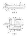
- FIG. 2 is a schematic vertical cross-sectional view illustrating the treatment area of the treatment instrument illustrated in FIG. 1A in an enlarged state;
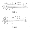
- FIG. 3A is a schematic diagram illustrating a treatment instrument of a treatment system according to a second embodiment, and illustrating a state in which a first treatment section of a treatment area is switched to an opened position;
- FIG. 3B is a schematic diagram illustrating the treatment instrument of the treatment system according to the second embodiment, and illustrating a state in which the first treatment section of the treatment area is switched to a closed position;
- FIG. 4 is a schematic vertical cross-sectional view illustrating the treatment area of the treatment instrument illustrated in FIG. 3A in an enlarged state;
- FIG. 5A is a schematic diagram illustrating a treatment instrument of a treatment system according to a third embodiment, and illustrating a state in which a first treatment section of a treatment area is switched to an opened position;
- FIG. 5B is a schematic diagram illustrating the treatment instrument of the treatment system according to the third embodiment, and illustrating a state in which the first treatment section of the treatment area is switched to a closed position;
- FIG. 6 is a schematic vertical cross-sectional view illustrating the treatment area of the treatment instrument illustrated in FIG. 5A in an enlarged state;
- FIG. 7A is a schematic diagram illustrating a treatment instrument of a treatment system according to a fourth embodiment, and illustrating a state in which a first treatment section of a treatment area is switched to an opened position;
- FIG. 7B is a schematic diagram illustrating the treatment instrument of the treatment system according to the fourth embodiment, and illustrating a state in which the first treatment section of the treatment area is switched to a closed position;
- FIG. 8A is a schematic diagram illustrating a treatment instrument of a treatment system according to a fifth embodiment, and illustrating a state in which a first treatment section of a treatment area is switched to an opened position;
- FIG. 8B is a schematic diagram illustrating the treatment instrument of the treatment system according to the fifth embodiment, and illustrating a state in which the first treatment section of the treatment area is switched to a closed position;
- FIG. 9 is a schematic diagram illustrating a treatment instrument of a treatment system according to a sixth embodiment.
- FIG. 10A is a schematic diagram illustrating a treatment area of the treatment instrument of the treatment system according to the sixth embodiment in an enlarged state, and illustrating a state in which the first treatment section of the treatment area is switched to an opened position;
- FIG. 10B is a schematic diagram illustrating the treatment area of the treatment instrument of the treatment system according to the sixth embodiment in an enlarged state, and illustrating a state in which the first treatment section of the treatment area is switched to a closed position;
- FIG. 11A is a schematic diagram illustrating a state in which a movement mechanism of a treatment instrument of a treatment system according to a seventh embodiment is operated to switch a first treatment section of a treatment area is switched to a closed position, and a second treatment section is retracted into the first treatment section;
- FIG. 11B is a schematic diagram illustrating a state in which the movement mechanism of the treatment instrument of the treatment system according to the seventh embodiment is operated to switch the first treatment section of the treatment area is switched to an opened position, and the second treatment section is retracted into the first treatment section;
- FIG. 11C is a schematic diagram illustrating a state in which the movement mechanism of the treatment instrument of the treatment system according to the seventh embodiment is operated to switch the first treatment section of the treatment area is switched to the closed position, and the second treatment section is caused to project from a distal end of the first treatment section.
- a first embodiment will be explained with reference to FIG. 1A to FIG. 2 .
- a treatment system (treatment instrument unit) 10 includes a treatment instrument 12 , and a controller 14 .
- a foot switch 16 is connected with the controller 14 .
- the treatment instrument 12 may be provided with a hand switch (not illustrated), together with the foot switch 16 , or instead of the foot switch 16 .
- a patient plate P is connected with the controller 14 .
- the treatment instrument 12 includes a cylindrical sheath 22 , a treatment area 24 projecting from a distal end 22 a of the sheath 22 , and a movement mechanism 26 .
- the sheath 22 defines a longitudinal axis L with its distal end 22 a and proximal end 22 b.
- the sheath 22 has electrical insulation property.
- the treatment area 24 includes a first treatment section 32 and a second treatment section 34 .
- the second treatment section 34 has a straight shape, but the shape of the second treatment section 34 is not particularly limited.
- the second treatment section 34 may have a proper shape, such as a hook shape and a spatula shape, to be used.
- the first treatment section 32 is capable of performing bipolar-type treatment.
- the first treatment section 32 includes a first body 42 and a second body 44 .
- Each of the first body 42 and the second body 44 is preferably formed of a metal material having conductivity.
- the first body 42 and the second body 44 may be formed of the same material, or different materials.
- the first body 42 and the second body 44 are electrically connected with the controller 14 .
- the first body 42 includes a shaft 42 a extending, for example, in parallel with the longitudinal axis L, and an action section 42 b formed by bending a distal end of the shaft 42 a in a direction crossing the longitudinal axis L.
- the action section 42 b is bent, for example, in a substantial L shape.
- the angle of the action section 42 b with respect to the shaft 42 a is illustrated as 90°, but the angle is not limited to 90°.
- the action section 42 b may be bent at a proper angle.
- a portion between the sections denoted by reference numerals 54 and 58 described later, that is, a boundary portion between the shaft 42 a and the action section 42 b is preferably formed as a curved surface, such as a chamfered surface, as a matter of course.
- the second body 44 is extended, for example, in parallel with the longitudinal axis L, in the same manner as the shaft 42 a of the first body 42 , and formed as, for example, a column-like rod.
- the action section 42 b of the first body 42 includes a first contact surface 52 treating the living tissue in a state of contacting the living tissue.
- the action section 42 b of the first body 42 projects from the distal end 22 a of the sheath 22 .
- the first contact surface 52 is opposed to the distal end 22 a of the sheath 22 .
- the first contact surface 52 is opposed to the proximal side along the longitudinal axis L.
- the second body 44 includes a second contact surface 62 disposed on the proximal side along the longitudinal axis L with respect to the first contact surface 52 , opposed to the first contact surface 52 , and treating the living tissue in a state of contacting the living tissue together with the first contact surface 52 .
- the second contact surface 62 is opposed to the distal side along the longitudinal axis L.
- the first contact surface 52 and the second contact surface 62 are preferably parallel with each other.
- each of the first contact surface 52 and the second contact surface 62 is used as a high-frequency electrode.
- the first contact surface 52 and the second contact surface 62 of the first treatment section 32 is capable of performing bipolar-type treatment to enable coagulation, such as sealing, of the held living tissue, when energy is provided in a state in which the living tissue is held between the first contact surface 52 and the second contact surface 62 .
- the living tissue is a blood vessel
- the held blood vessel is sealed by bipolar-type treatment.
- the first body 42 includes an electrical insulation section 54 to prevent treatment of the living tissue, when the energy described above is provided in a state of contacting the living tissue.
- the electrical insulation section 54 is formed of, for example, insulation coating.
- the electrical insulation section 54 preferably has heat resistance.
- the electrical insulation section 54 is formed on a back surface with respect to the first contact surface 52 . Specifically, the electrical insulation section 54 is disposed on the distal end surface of the first body 42 , and opposed to the distal side along the longitudinal axis L.
- a portion denoted by reference numeral 56 disposed in the vicinity of the boundary with the action section 42 b and close to the distal end of the second body 44 maybe formed as an electrode, in the same manner as the first contact surface 52 , or may be formed as an electrical insulation section.
- An electrical insulation section 58 is formed on a back surface (far surface) of the portion denoted by reference numeral 56 .
- the electrical insulation sections 54 and 58 are preferably continuously formed in seamless manners.
- the electrical insulation section 58 is formed of, for example, insulation coating.
- the side surface between the first contact surface 52 and the electrical insulation section 54 , the side surface between the portion denoted by reference numeral 56 and the electrical insulation section 58 , and a far end 42 c of the action section 42 b of the first body 42 with respect to the shaft 42 a that is long along the longitudinal axis L are preferably formed as an electrical insulation section 59 .
- the far end 42 c formed an opening inlet through which the living tissue is disposed between the second contact surface 62 of the second body 44 and the opening inlet.
- the second body 44 includes an electrical insulation section 64 preventing treatment of the living tissue when the energy described above is provided in a state of contacting the living tissue.
- the electrical insulation section 64 is formed in a portion excluding the second contact surface 62 .
- an external circumferential surface around the longitudinal axis of the second body 44 is provided with insulation coating.
- insulation coating a sliding surface between the first body 42 and the second body 44 is electrically insulated.
- the electrical insulation section 64 preferably has heat resistance.
- the first body 42 illustrated in FIG. 1A and FIG. 1B is fixed with respect to the sheath 22
- the second body 44 is movable with respect to the sheath 22 along the longitudinal axis L.
- the movement mechanism 26 is capable of moving the second body 44 within a predetermined range along the longitudinal axis L.
- a proper mechanism may be used as the movement mechanism 26 .
- a linear motor may be used to move the second body 44 within a predetermined range along the longitudinal axis L with respect to the sheath 22 .
- This explanation illustrates an example of the movement mechanism 26 , in which the user manually moves the second body 44 with respect to the sheath 22 along the longitudinal axis L.
- the sheath 22 is provided with a groove 72 .
- the groove 72 is longer along the longitudinal axis L than in a circumferential direction of the longitudinal axis L, and defines the movement range in which the second body 44 is moved along the longitudinal axis L.
- the groove 72 is provided with a slide lever 74 as an operation body.
- the slide lever 74 is movable between a distal end and a proximal end of the groove 72 along the longitudinal axis L.
- the slide lever 74 has electrical insulation property.
- the slide lever 74 is coupled with the second body 44 .
- the movement mechanism 26 includes the groove 72 formed in the sheath 22 , and the slide lever 74 coupled with the second body 44 .
- FIG. 1B illustrate that the groove 72 and the slide lever 74 are located in a position close to the proximal end 22 b in the sheath 22 , but the groove 72 and the slide lever 74 may be located in a position close to the distal end 22 a, as a matter of course.
- the movement mechanism 26 is capable of causing the slide lever 74 to abut against the distal end of the groove 72 , when the slide lever 74 is moved along the longitudinal axis L toward the distal side of the sheath 22 .
- the movement mechanism 26 is capable of causing the slide lever 74 to abut against the proximal end of the groove 72 , when the slide lever 74 is moved along the longitudinal axis L toward the proximal side of the sheath 22 .
- the groove 72 can define the movable range of the slide lever 74 .
- the slide lever 74 When the slide lever 74 is caused to abut against the distal end of the groove 72 of the sheath 22 along the longitudinal axis L, the second contact surface 62 of the second body 44 is moved toward the distal side along the longitudinal axis L and close to the first contact surface 52 of the first body 42 . For this reason, the first treatment section is changed to a closed position in which the first contact surface 52 of the first body 42 and the second contact surface 62 of the second body 44 are close to each other. In this state, the first contact surface 52 and the second contact surface 62 do not contact each other, but a small space is formed therebetween.
- the slide lever 74 When the slide lever 74 is caused to abut against the proximal end of the groove 72 of the sheath 22 along the longitudinal axis L, the second contact surface 62 of the second body 44 is moved toward the proximal side along the longitudinal axis L and distant from the first contact surface 52 of the first body 42 . For this reason, the first treatment section is changed to an opened position in which the first contact surface 52 of the first body 42 and the second contact surface 62 of the second body 44 are distant from each other. Operating the slide lever 74 enables adjustment of a distance between the first contact surface 52 and the second contact surface 62 , and adjustment of the opening quantity.
- the movement mechanism 26 is capable of moving the second body 44 along the longitudinal axis L, to switch between the closed position in which the first contact surface 52 and the second contact surface 62 are close to each other, and the opened position in which the first contact surface 52 and the second contact surface 62 are distant from each other.
- the second treatment section 34 is disposed on the distal side with respect to the first treatment section 32 along the longitudinal axis L.
- the second treatment section 34 is formed as one unitary piece with the first body 42 .
- the second treatment section 34 has the same potential as that of the first body 42 .
- the second treatment section 34 projects toward the distal side along the longitudinal axis L with respect to the electrical insulation section 54 on the distal end surface of the first body 42 .
- the second treatment section 34 is formed in a rod shape thinner than the second body 44 .
- FIG. 1A to FIG. 2 illustrate that the second treatment section 34 has a shape extending in a straight manner along the longitudinal axis L, but the shape may be properly set as described above.
- the second treatment section 34 is used as a high-frequency electrode.
- the second treatment section 34 is capable of performing monopolar-type treatment to incise and exfoliate the contacting living tissue, when energy is provided in a state of contacting the living tissue between the second treatment section 34 and the patient plate P attached to the patient.
- the second treatment section 34 is disposed on the distal side with respect to the first treatment section 32 along the longitudinal axis L when the first contact surface 52 and the second contact surface 62 are located in the closed position, and capable of incising or exfoliating the living tissue by applying energy to the living tissue.
- the controller 14 is capable of performing control to output energy to the first treatment section 32 and perform bipolar-type treatment with the first treatment section 32 , in accordance with an instruction with the foot switch 16 , for example, and capable of performing control to output energy to the second treatment section 34 and perform monopolar-type treatment with the second treatment section 34 .
- the first body 42 is used when either of the treatments is performed.
- the foot switch 16 of the treatment system 10 includes a first switch 16 a and a second switch 16 b.
- the first switch 16 a outputs signal to the controller 14 to output energy from the controller 14 , when bipolar-type treatment is performed with the first treatment section 32 .
- the second switch 16 b outputs signal to the controller 14 to output energy from the controller 14 , when monopolar-type treatment is performed with the second treatment section 34 .
- the treatment instrument 12 is used together with an endoscope (not illustrated), through a trocar.
- the user attaches the patient plate P to a proper position of the patient.
- the user properly holds the treatment instrument 12 , and causes the treatment area 24 to face a membrane tissue or a layered tissue in the body, while checking the observed image of the endoscope. Since the second treatment section 34 of the treatment area 24 is formed thin, its approaching property is maintained.
- the second switch 16 b is pressed, to perform monopolar-type treatment on the living tissue with the second treatment section 34 of the treatment area 24 .
- the monopolar-type high-frequency energy is applied to the living tissue serving as treatment target, and the high-frequency current is recovered with the patient plate P attached to the patient, to incise the living tissue contacting the second treatment section 34 , or separate the layers.
- the operation of pressing the second switch 16 b is performed only when treatment such as incision is to be actually performed, and usually pressing of the second switch 16 b is released.
- the electrical insulation sections 54 , 58 , and 59 of the first treatment section 32 contact the living tissue in a proper position, no current flows through the contacting living tissue.
- the electrical insulation sections 54 , 58 , and 59 of the first treatment section 32 prevent a high-frequency current from flowing through the living tissue unintentionally. Specifically, this structure prevents the treatment area 24 from performing unintentional treatment.
- a blood vessel may be exposed, in the case of repeating treatment to incise a living tissue in a thin-membrane shape or separate the layers of the living tissue.
- the blood vessel is sealed, that is, coagulated, to prevent bleeding from the blood vessel.
- the user operates the slide lever 74 along the groove 72 , to switch the first contact surface 52 of the first body 42 and the second contact surface 62 of the second body 44 to the opened position.
- the blood vessel is disposed between the first contact surface 52 of the first body 42 and the second contact surface 62 of the second body 44 in the first treatment section 32 .
- the user moves the slide lever 74 to switch the first contact surface 52 of the first body 42 and the second contact surface 62 of the second body 44 to the closed position.
- the blood vessel contacts both the first contact surface 52 of the first body 42 and the second contact surface 62 of the second body 44 .
- the first contact surface 52 and the second contact surface 62 are not electrically connected.
- the first switch 16 a is pressed, to perform bipolar-type treatment on the living tissue serving as treatment target, such as a blood vessel, with the first treatment section 32 .
- High-frequency energy is applied to the blood vessel (living tissue) serving as treatment target, to coagulate the blood vessel contacting both the first contact surface 52 of the first body 42 and the second contact surface 62 of the second body 44 in the first treatment section 32 , by Joule heat. This operation prevents bleeding from the coagulated region.
- the second treatment section 34 is used to cut the coagulated region. This operation can be performed only by moving the treatment area 24 , and does not require change of the treatment instrument 12 itself.
- the first and the second bodies 42 and 44 are only moved relatively in the front and the rear direction.
- This structure is simple, and hardly hampers visibility when a blood vessel or the like is disposed between the first contact surface 52 of the first body 42 and the second contact surface 62 of the second body 44 .
- bipolar-type treatment is performed with the first treatment section 32 when a blood vessel or the like is exposed. If necessary, monopolar-type treatment is performed with the second treatment section 34 , to cut the blood vessel sealed by the bipolar-type treatment, and desired treatment is ended.
- incision or separation can be performed on the living tissue serving as treatment target.
- the blood vessel can be sealed, while the state in which the treatment area 24 is brought close to the living tissue is maintained. Accordingly, treatment on the living tissue serving as treatment target can be performed with one treatment instrument 12 , without changing the treatment instrument.
- This structure enables reduction in treatment time, and greatly improves treatment property for the living tissue serving as treatment target.
- This structure maintains the state in which the treatment area 24 is always disposed close to the treatment target, while the treatment area 24 is disposed within the observation visual field of the endoscope.
- This structure removes the labor of disposing the treatment area 24 in the visual field of the endoscope, when once the treatment area 24 is disposed in the visual field of the endoscope.
- treatment can be performed in the state where the treatment area 24 is disposed in the visual field of the endoscope, only by once causing the treatment area 24 to face the living tissue serving as treatment target.
- the following is explanation of a second embodiment, with reference to FIG. 3A and FIG. 3B .
- the present embodiment is a modification of the first embodiment.
- the same members or members having the same functions as the members explained in the first embodiment are denoted by the same reference numerals as much as possible, and detailed explanation thereof is omitted.
- each of the first contact surface 52 of the first body 42 and the second contact surface 62 of the second body 44 is formed as an inclined surface inclined with respect to a state of being orthogonal to the longitudinal axis L.
- a normal N 1 of the first contact surface 52 of the first body 42 is directed toward the proximal side along the longitudinal axis L, and toward the upper side in FIG. 3A opposite to the shaft 42 a of the first body 42 .
- the first contact surface 52 of the first body 42 is formed as an inclined surface, for example, when the treatment area 24 is moved toward the distal side along the longitudinal axis L, the first contact surface 52 is capable of easily guiding, for example, a blood vessel, between the first body 42 and the second body 44 .
- a normal N 2 of the second contact surface 62 of the second body 44 is directed toward the distal side along the longitudinal axis L, and toward the lower side in FIG. 3A and in the vicinity of the boundary between the shaft 42 a and the action section 42 b of the first body 42 .
- the normals N 1 and N 2 are preferably parallel with each other.
- the first contact surface 52 and the second contact surface 62 are preferably parallel with each other.
- the first contact surface 52 of the first body 42 and the second contact surface 62 of the second body 44 secure larger contact areas for the living tissue, such as a blood vessel, than those of the first contact surface 52 of the first body 42 and the second contact surface 62 of the second body 44 explained in the first embodiment.
- This structure easily increases the contact area when, for example, a thicker blood vessel is brought into contact with the first contact surface 52 of the first body 42 and the second contact surface 62 of the second body 44 .
- This structure also enables treatment, such as sealing the living tissue with a substantially uniform thickness, when the living tissue such as a blood vessel is disposed between the first contact surface 52 of the first body 42 and the second contact surface 62 of the second body 44 .
- a first switch 18 a and a second switch 18 b are provided on the external circumferential surface of the sheath 22 .
- the controller 14 issues an instruction to output energy from the controller 14 , when bipolar-type treatment is performed with the first treatment section 32 .
- the controller 14 also issues an instruction to output energy from the controller 14 , when monopolar-type treatment is performed with the second treatment section 34 .
- Output of energy from the controller 14 can be controlled also by operation of the foot switch 16 , as well as the switches 18 a and 18 b on the external circumferential surface of the sheath, as a matter of course.
- the treatment instrument 12 according to the present embodiment can be used in the same manner as the treatment instrument 12 explained in the first embodiment, and explanation of the functions thereof is omitted.
- the contact areas are increased when a blood vessel or the like is held with the first treatment section 32 . Accordingly, this structure enables securer sealing treatment even on a relatively thick blood vessel.
- a projection 52 a having electrical insulation property is disposed on the first contact surface 52 of the first body 42 .
- the projection 52 a is preferably disposed in the vicinity of the far end 42 c with respect to the shaft 42 a that is long along the longitudinal axis L, in the action section 42 b of the first body 42 .
- Existence of the projection 52 a also allows a blood vessel to enter a space between the first contact surface 52 of the first body 42 and the second contact surface 62 of the second body 44 , when the first body 42 and the second body 44 are located in the opened position.
- the projection 52 a suppresses the blood vessel from unintentionally escaping from the space between the first contact surface 52 of the first body 42 and the second contact surface 62 of the second body 44 .
- the projection 52 a can also be used as a spacer maintaining a distance between the first contact surface 52 and the second contact surface 62 .
- the present embodiment is a modification of the first embodiment and the second embodiment.
- the same members or members having the same functions as the members explained in the first and the second embodiments are denoted by the same reference numerals as much as possible, and detailed explanation thereof is omitted.
- the first contact surface 52 of the first body 42 includes a first heater 53 , instead of being used as a high-frequency electrode.
- the second contact surface 62 of the second body 44 includes a second heater 63 , instead of being used as a high-frequency electrode.
- the first heater 53 and the second heater 63 that is, the first contact surface 52 and the second contact surface 62 may contact each other, as illustrated in FIG. 5B .
- Each of the first heater 53 and the second heater 63 is preferably formed in a plate shape enabling increase in temperature to approximately several hundred degrees C. for several seconds.
- the treatment instrument 12 according to the present embodiment can be used in the same manner as the treatment instrument 12 explained in the first embodiment, and explanation of the functions thereof is omitted.
- this structure With the first heater 53 and the second heater 63 , this structure enables coagulation of the living tissue with the first treatment section 32 , and treatment to seal the living tissue when the living tissue is a blood vessel.
- this structure With the first heater 53 and the second heater 63 , this structure enables incision of the living tissue, as well as coagulation of the living tissue, by setting the energy quantity.
- the treatment instrument 12 enables treatment, such as coagulation of the living tissue, with the first treatment section 32 without using a high-frequency current.
- the energy used for treatment with the treatment instrument 12 is not limited to high-frequency energy, but thermal energy may be properly used.
- the treatment instrument 12 includes at least one of the first heater 53 and the second heater 63 . Specifically, this explanation illustrates the case of including both the first heater 53 and the second heater 63 , but the treatment instrument 12 may include only one of them.
- the heat when energy is applied to the first heater 53 to cause the first heater 53 to generate heat, the heat enables sealing of the living tissue such as a blood vessel in the first treatment section 32 , and enables transmission of heat to the second treatment section 34 through the action section 42 b of the first body 42 .
- the first heater 53 set to a certain temperature enables incision of the tissue in a coagulated state, such as a blood vessel, as well as coagulation of the living tissue.
- the first heater 53 set to a certain temperature enables incision of the living tissue with the heat from the first heater 53 , without providing energy to the second treatment section 34 , immediately after the blood vessel is sealed.
- the present embodiment is a modification of the second embodiment.
- the first contact surface 52 and the second contact surface 62 that is, the first heater 53 and the second heater 63 may be formed as inclined surfaces illustrated in FIG. 3A to FIG. 4 , as a matter of course.
- the first contact surface 52 of the first treatment section 32 may be formed as an electrode, and the first heater 53 may be embedded in the first contact surface 52 .
- the second contact surface 62 of the first treatment section 32 may be formed as an electrode, and the second heater 63 may be embedded in the second contact surface 62 .
- each of the first contact surface 52 and the second contact surface 62 of the first treatment section 32 is used as a high-frequency electrode and as a heater. In such a case, as explained in the first and the second embodiments, the first contact surface 52 and the second contact surface 62 do not contact each other.
- the first contact surface 52 and the second contact surface 62 are capable of coagulating and incising the living tissue with the thermal energy from the heaters 53 and 63 , respectively, while sealing the living tissue such as a blood vessel with high-frequency energy.
- a relatively thick blood vessel may require a long time for sealing the blood vessel with high-frequency energy, but the treatment ability can be increased by using the high-frequency energy together with the thermal energy from the heater 53 , to shorten the time required for sealing the blood vessel.
- the present embodiment is a modification of the first to the third embodiments.
- the same members or members having the same functions as the members explained in the first to the third embodiments are denoted by the same reference numerals as much as possible, and detailed explanation thereof is omitted.
- the first body 42 of the first treatment section 32 is fixed with respect to the sheath 22
- the second body 44 is movable with respect to the first body 42 and the sheath 22
- the present embodiment has a structure in which the second body 44 of the first treatment section 32 is fixed with respect to the sheath 22 , and the first body 42 is movable with respect to the second body 44 and the sheath 22 .
- the movement mechanism 26 is capable of moving the first body 42 within a predetermined range along the longitudinal axis L. As explained in the first embodiment, a proper mechanism may be used as the movement mechanism 26 .
- a linear motor may be used to move the first body 42 within a predetermined range along the longitudinal axis L with respect to the sheath 22 .
- This explanation illustrates an example of the movement mechanism 26 , in which the user manually moves the first body 42 with respect to the sheath 22 along the longitudinal axis L.
- the groove 72 formed in the sheath 22 is provided with a slide lever 74 as an operation body.
- the slide lever 74 has electrical insulation property.
- the slide lever 74 is coupled with the first body 42 .
- the movement mechanism 26 includes the groove 72 formed in the sheath 22 , and the slide lever 74 coupled with the first body 42 .
- the movement mechanism 26 is capable of defining the movable range of the slide lever 74 by the groove 72 .
- the slide lever 74 is caused to contact the distal end of the groove 72 of the sheath 22 along the longitudinal axis L, the first contact surface 52 of the first body 42 is moved toward the distal side along the longitudinal axis L and distant from the second contact surface 62 of the second body 44 .
- the first contact surface 52 of the first body 42 and the second contact surface 62 of the second body 44 are distant from each other, and in the opened position.
- the slide lever 74 When the slide lever 74 is caused to contact against the proximal end of the groove 72 of the sheath 22 along the longitudinal axis L, the first contact surface 52 of the first body 42 is moved toward the proximal side along the longitudinal axis L and close to the second contact surface 62 of the second body 44 . For this reason, the first contact surface 52 of the first body 42 and the second contact surface 62 of the second body 44 are close to each other and in the closed position.
- the movement mechanism 26 is capable of moving the first body 42 along the longitudinal axis L, to switch between the closed position in which the first contact surface 52 and the second contact surface 62 are close to each other, and the opened position in which the first contact surface 52 and the second contact surface 62 are distant from each other. In the closed position, the first contact surface 52 and the second contact surface 62 do not contact each other, but a small gap is formed therebetween.
- treatment instrument 12 Other structures of the treatment instrument 12 are the same as those of the first embodiment, and explanation is omitted herein.
- the treatment instrument 12 according to the present embodiment can be used in the same manner as the treatment instrument 12 explained in the first embodiment, and explanation of functions thereof is omitted.
- the treatment instrument 12 according to the present embodiment can be used in the same manner as explained in the first embodiment, even when the first body 42 is formed movable with respect to the sheath 22 and the second body 44 .
- the present embodiment is a modification of the fourth embodiment.
- the same members or members having the same functions as the members explained in the fourth embodiment are denoted by the same reference numerals as much as possible, and detailed explanation thereof is omitted.
- the distal end of the second body 44 is provided with a through hole 44 a formed in parallel with the longitudinal axis L.
- An internal circumferential surface of the through hole 44 a is electrically insulated.
- the shaft 42 a of the first body 42 includes a distal side member 82 , a proximal side member 84 , and an energizing body 86 .
- the proximal side member 84 is fixed with respect to the sheath 22 .
- the distal side member 82 is coupled with the proximal side member 84 through the energizing body 86 .
- a proper spring such as a helical extension spring is used as the energizing member 86 .
- the energizing body 86 energizes a proximal end 82 a of the distal side member 82 toward a distal end 84 a of the proximal side member 84 .
- the energizing body 86 may have electrical conductivity to electrically connect the proximal side member 84 with the distal side member 82 .
- the energizing body 86 having electrical insulation property may be used, when the proximal side member 84 is electrically connected with the distal side member 82 with a lead (not illustrated).
- the distal side member 82 is disposed in a state of running through the through hole 44 a of the second body 44 .
- the slide lever 74 having electrical insulation property is fixed to the distal side member 82 .
- the slide lever 74 is movable within a predetermined range with the groove 72 .
- the treatment instrument 12 according to the present embodiment can be used in the same manner as the treatment instrument 12 explained in the first embodiment, and explanation of functions thereof is omitted.
- the treatment instrument 12 enables application of pressure to the living tissue with the energizing body 86 , in the state where the living tissue such as a blood vessel is disposed between the first contact surface 52 and the second contact surface 62 .
- the living tissue such as a blood vessel is disposed between the first contact surface 52 and the second contact surface 62 .
- the user's operation of pressing the slide lever 74 can be omitted, according to the type of the living tissue.
- the energizing force of the energizing member 86 enables uniform treatment, such as coagulation and sealing, for the living tissue.
- the present embodiment is a modification of the first to the fifth embodiments.
- the same members or members having the same functions as the members explained in the first to the fifth embodiments are denoted by the same reference numerals as much as possible, and detailed explanation thereof is omitted.
- the second treatment section 34 is formed as a member separated from the first body 42 of the first treatment section 32 , not as a united member. For this reason, the second treatment section 34 is not required to have the same potential as that of the first body 42 of the first treatment section 32 .
- the first body 42 of the first treatment section 32 includes a channel 92 formed in parallel with the longitudinal axis L and including an insulated internal circumferential surface.
- the channel 92 is formed on the back surface side with respect to the region denoted by reference numeral 56 .
- the second treatment section 34 in a rod shape is disposed in the channel 92 .
- the second treatment section 34 is fixed with respect to the sheath 22 .
- the second treatment section 34 is covered with the channel 92 .
- the second treatment section 34 projects from the channel 92 .
- the user when the user uses the treatment instrument 12 to perform treatment, the user switches the first treatment section 32 to the closed position, to cause the second treatment section 34 to project from the first treatment section 32 toward the distal end side.
- the second switch 16 b of the foot switch 16 is pressed, to perform monopolar-type treatment on the living tissue with the second treatment section 34 of the treatment area 24 .
- Monopolar-type high-frequency energy is applied to the living tissue serving as treatment target, and the high-frequency energy is recovered with the patient plate P attached to the patient, to incise the living tissue caused to contact the second treatment section 34 , or separate layers of the living tissue.
- the electrical insulation sections 54 , 58 , and 59 of the first treatment section 32 contact the living tissue in a proper position, no electricity flows through the contacting living tissue.
- the electrical insulation sections 54 , 58 , and 59 of the first treatment section 32 prevent a high-frequency current from unintentionally flowing through the living tissue. Specifically, this structure prevents unintentional treatment with the treatment area 24 .
- the user switches the first treatment section 32 to the opened position, to retract the second treatment section 34 into the channel 92 with respect to the first treatment section 32 .
- the blood vessel is disposed between the first contact surface 52 of the first body 42 of the first treatment section 32 and the second contact surface 62 of the second treatment section 34 .
- the user switches the first treatment section 32 to the closed position, to bring the blood vessel into contact with both the first contact surface 52 of the first body 42 and the second contact surface 62 of the second treatment section 34 .
- the first switch 16 a is pressed, to perform bipolar-type treatment on the living tissue serving as treatment target, such as a blood vessel, with the first treatment section 32 , and seal the blood vessel.
- the shaft 42 a of the first body 42 illustrated in FIG. 9 to FIG. 10B may be provided to be movable along the longitudinal axis L, in the through hole 44 a of the second body 44 .
- the present embodiment is a modification of the first to the sixth embodiments.
- the same members or members having the same functions as the members explained in the first to the sixth embodiments are denoted by the same reference numerals as much as possible, and detailed explanation thereof is omitted.
- the present embodiment is a modification of the sixth embodiment.
- the movement mechanism 26 includes the groove 72 , a first slide lever 74 a, and a second slide lever 74 b.
- the groove 72 is shared between the first slide lever 74 a and the second slide lever 74 b.
- the first slide lever 74 a is disposed on the distal side in the groove 72 along the longitudinal axis L, with respect to the second slide lever 74 b.
- the first slide lever 74 a is coupled with the second treatment section 34 .
- the second slide lever 74 b is coupled with the shaft 42 a of the first body 42 of the first treatment section 32 .
- the first slide lever 74 a and the second slide lever 74 b are positioned on the most proximal side with respect to the groove 72 .
- the first treatment section 32 is switched to the closed position, and the second treatment section 34 is disposed on the proximal side with respect to the distal end of the action section 42 b of the first body 42 of the first treatment section 32 .
- the first slide lever 74 a and the second slide lever 74 b are positioned on the most distal side with respect to the groove 72 .
- the first treatment section 32 is switched to the opened position, and the second treatment section 34 is disposed on the proximal side with respect to the distal end of the action section 42 b of the first body 42 of the first treatment section 32 .
- the first slide lever 74 a is positioned on the most distal side with respect to the groove 72
- the second slide lever 74 b is positioned on the most proximal side with respect to the groove 72 .
- the first treatment section 32 is switched to the closed position, and the second treatment section 34 is caused to project with respect to the distal end of the action section 42 b of the first body 42 of the first treatment section 32 .
- the second treatment section 34 is enabled to project to the distal side along the longitudinal axis with respect to the first body 42 of the first treatment section 32 .
- the user uses the treatment instrument 12 to perform treatment and dispose the treatment area 24 in a proper position, the user moves the first and the second slide levers 74 a and 74 b of the movement mechanism 26 to the state illustrated in FIG. 11A , or the state illustrated in FIG. 11C .
- the first and the second slide levers 74 a and 74 b are moved to the state illustrated in FIG. 11A or FIG. 11C , to cause the second treatment section 34 to project with respect to the distal end of the action section 42 b of the first body 42 of the first treatment section 32 .
- the second switch 16 b of the foot switch 16 is pressed, to perform monopolar-type treatment on the living tissue with the second treatment section 34 of the treatment area 24 .
- This structure causes the second treatment section 34 to incise the contacting living tissue such as a thin membrane, or separate layers of the living tissue.
- the user moves the first and the second slide levers 74 a and 74 b to the state illustrated in FIG. 11B , to switch the first treatment section 32 to the opened section, and retract the second treatment section 34 into the channel 92 with respect to the first treatment section 32 .
- the blood vessel is disposed between the first contact surface 52 of the first body 42 of the first treatment section 32 and the second contact surface 62 of the second treatment section 34 .
- the user moves the first and the second slide levers 74 a and 74 b to the state illustrated in FIG.
- the first switch 16 a is pressed, to perform bipolar-type treatment on the living tissue serving as treatment target, such as a blood vessel, with the first treatment section 32 , and seal the blood vessel.
- the second treatment section 34 can be contained in the first treatment section 32 , as illustrated in FIG. 11A and FIG. 11B . This structure prevents the second treatment section 34 from becoming an obstacle.
Landscapes
- Health & Medical Sciences (AREA)
- Surgery (AREA)
- Engineering & Computer Science (AREA)
- Life Sciences & Earth Sciences (AREA)
- Biomedical Technology (AREA)
- Otolaryngology (AREA)
- Nuclear Medicine, Radiotherapy & Molecular Imaging (AREA)
- Plasma & Fusion (AREA)
- Physics & Mathematics (AREA)
- Heart & Thoracic Surgery (AREA)
- Medical Informatics (AREA)
- Molecular Biology (AREA)
- Animal Behavior & Ethology (AREA)
- General Health & Medical Sciences (AREA)
- Public Health (AREA)
- Veterinary Medicine (AREA)
- Surgical Instruments (AREA)
Abstract
Description
- This application is a Continuation Application of PCT Application No. PCT/JP2016/065048, filed May 20, 2016 and based upon and claiming the benefit of priority from prior Japanese Patent Application No. 2015-142362, filed Jul. 16, 2015, the entire contents of all of which are incorporated herein by reference.
- The present invention relates to a treatment instrument.
- For example, Japanese Patent Application KOKAI Publication No. 2001-61848 discloses a treatment instrument capable of holding a living tissue between a fixed electrode on the distal side and a movable electrode movable to slide along a longitudinal axis direction toward the fixed electrode, to coagulate the living tissue. For example, when a living tissue serving as a treatment target exists in a body cavity or the like, an endoscope and the treatment instrument are put into the body cavity through separate trocars, to perform treatment.
- According to an aspect of the invention, there is provided a treatment instrument includes: a sheath which defines a longitudinal axis by a distal end and a proximal end; a first treatment section which includes a first body including a first contact surface configured to contact a living tissue, and a second body including a second contact surface opposed to the first contact surface on a proximal side with respect to the first contact surface and configured to contact the living tissue, and which is configured to apply energy to the living tissue held between the first contact surface and the second contact surface to coagulate the living tissue; a movement mechanism which is configured to move at least one of the first body and the second body along the longitudinal axis, to switch between a closed position in which the first contact surface and the second contact surface are close to each other, and an opened position in which the first contact surface and the second contact surface are distant from each other; and a second treatment section which is disposed on a distal side along the longitudinal axis with respect to the first treatment section when the first contact surface and the second contact surface are located in the closed position, and which is configured to apply energy to the living tissue to incise or separate the living tissue.
- Advantages of the invention will be set forth in the description which follows, and in part will be obvious from the description, or may be learned by practice of the invention. Advantages of the invention may be realized and obtained by means of the instrumentalities and combinations particularly pointed out hereinafter.
- The accompanying drawings, which are incorporated in and constitute apart of the specification, illustrate embodiments of the invention, and together with the general description given above and the detailed description of the embodiments given below, serve to explain the principles of the invention.
-
FIG. 1A is a schematic diagram illustrating a treatment system according to a first embodiment, and illustrating a state in which a first treatment section of a treatment area of a treatment instrument is switched to an opened position; -
FIG. 1B is a schematic diagram illustrating the treatment instrument of the treatment system according to the first embodiment, and illustrating a state in which the first treatment section of the treatment area is switched to a closed position; -
FIG. 2 is a schematic vertical cross-sectional view illustrating the treatment area of the treatment instrument illustrated inFIG. 1A in an enlarged state; -
FIG. 3A is a schematic diagram illustrating a treatment instrument of a treatment system according to a second embodiment, and illustrating a state in which a first treatment section of a treatment area is switched to an opened position; -
FIG. 3B is a schematic diagram illustrating the treatment instrument of the treatment system according to the second embodiment, and illustrating a state in which the first treatment section of the treatment area is switched to a closed position; -
FIG. 4 is a schematic vertical cross-sectional view illustrating the treatment area of the treatment instrument illustrated inFIG. 3A in an enlarged state; -
FIG. 5A is a schematic diagram illustrating a treatment instrument of a treatment system according to a third embodiment, and illustrating a state in which a first treatment section of a treatment area is switched to an opened position; -
FIG. 5B is a schematic diagram illustrating the treatment instrument of the treatment system according to the third embodiment, and illustrating a state in which the first treatment section of the treatment area is switched to a closed position; -
FIG. 6 is a schematic vertical cross-sectional view illustrating the treatment area of the treatment instrument illustrated inFIG. 5A in an enlarged state; -
FIG. 7A is a schematic diagram illustrating a treatment instrument of a treatment system according to a fourth embodiment, and illustrating a state in which a first treatment section of a treatment area is switched to an opened position; -
FIG. 7B is a schematic diagram illustrating the treatment instrument of the treatment system according to the fourth embodiment, and illustrating a state in which the first treatment section of the treatment area is switched to a closed position; -
FIG. 8A is a schematic diagram illustrating a treatment instrument of a treatment system according to a fifth embodiment, and illustrating a state in which a first treatment section of a treatment area is switched to an opened position; -
FIG. 8B is a schematic diagram illustrating the treatment instrument of the treatment system according to the fifth embodiment, and illustrating a state in which the first treatment section of the treatment area is switched to a closed position; -
FIG. 9 is a schematic diagram illustrating a treatment instrument of a treatment system according to a sixth embodiment; -
FIG. 10A is a schematic diagram illustrating a treatment area of the treatment instrument of the treatment system according to the sixth embodiment in an enlarged state, and illustrating a state in which the first treatment section of the treatment area is switched to an opened position; -
FIG. 10B is a schematic diagram illustrating the treatment area of the treatment instrument of the treatment system according to the sixth embodiment in an enlarged state, and illustrating a state in which the first treatment section of the treatment area is switched to a closed position; -
FIG. 11A is a schematic diagram illustrating a state in which a movement mechanism of a treatment instrument of a treatment system according to a seventh embodiment is operated to switch a first treatment section of a treatment area is switched to a closed position, and a second treatment section is retracted into the first treatment section; -
FIG. 11B is a schematic diagram illustrating a state in which the movement mechanism of the treatment instrument of the treatment system according to the seventh embodiment is operated to switch the first treatment section of the treatment area is switched to an opened position, and the second treatment section is retracted into the first treatment section; and -
FIG. 11C is a schematic diagram illustrating a state in which the movement mechanism of the treatment instrument of the treatment system according to the seventh embodiment is operated to switch the first treatment section of the treatment area is switched to the closed position, and the second treatment section is caused to project from a distal end of the first treatment section. - Embodiments will be explained hereinafter with reference to drawings.
- A first embodiment will be explained with reference to
FIG. 1A toFIG. 2 . - As illustrated in
FIG. 1A , a treatment system (treatment instrument unit) 10 according to the present embodiment includes atreatment instrument 12, and acontroller 14. Afoot switch 16 is connected with thecontroller 14. Thetreatment instrument 12 may be provided with a hand switch (not illustrated), together with thefoot switch 16, or instead of thefoot switch 16. A patient plate P is connected with thecontroller 14. - As illustrated in
FIG. 1A andFIG. 1B , thetreatment instrument 12 includes acylindrical sheath 22, atreatment area 24 projecting from adistal end 22 a of thesheath 22, and amovement mechanism 26. Thesheath 22 defines a longitudinal axis L with itsdistal end 22 a andproximal end 22 b. Thesheath 22 has electrical insulation property. Thetreatment area 24 includes afirst treatment section 32 and asecond treatment section 34. InFIG. 1A toFIG. 2 , thesecond treatment section 34 has a straight shape, but the shape of thesecond treatment section 34 is not particularly limited. Thesecond treatment section 34 may have a proper shape, such as a hook shape and a spatula shape, to be used. - In the present embodiment, the
first treatment section 32 is capable of performing bipolar-type treatment. Thefirst treatment section 32 includes afirst body 42 and asecond body 44. Each of thefirst body 42 and thesecond body 44 is preferably formed of a metal material having conductivity. Thefirst body 42 and thesecond body 44 may be formed of the same material, or different materials. Thefirst body 42 and thesecond body 44 are electrically connected with thecontroller 14. - In the present embodiment, the
first body 42 includes ashaft 42 a extending, for example, in parallel with the longitudinal axis L, and anaction section 42 b formed by bending a distal end of theshaft 42 a in a direction crossing the longitudinal axis L. Theaction section 42 b is bent, for example, in a substantial L shape. InFIG. 1A toFIG. 2 , the angle of theaction section 42 b with respect to theshaft 42 a is illustrated as 90°, but the angle is not limited to 90°. Theaction section 42 b may be bent at a proper angle. A portion between the sections denoted byreference numerals shaft 42 a and theaction section 42 b is preferably formed as a curved surface, such as a chamfered surface, as a matter of course. Thesecond body 44 is extended, for example, in parallel with the longitudinal axis L, in the same manner as theshaft 42 a of thefirst body 42, and formed as, for example, a column-like rod. - The
action section 42 b of thefirst body 42 includes afirst contact surface 52 treating the living tissue in a state of contacting the living tissue. Theaction section 42 b of thefirst body 42 projects from thedistal end 22 a of thesheath 22. Thefirst contact surface 52 is opposed to thedistal end 22 a of thesheath 22. Specifically, thefirst contact surface 52 is opposed to the proximal side along the longitudinal axis L. - The
second body 44 includes asecond contact surface 62 disposed on the proximal side along the longitudinal axis L with respect to thefirst contact surface 52, opposed to thefirst contact surface 52, and treating the living tissue in a state of contacting the living tissue together with thefirst contact surface 52. Thesecond contact surface 62 is opposed to the distal side along the longitudinal axis L. Thefirst contact surface 52 and thesecond contact surface 62 are preferably parallel with each other. - In the present embodiment, each of the
first contact surface 52 and thesecond contact surface 62 is used as a high-frequency electrode. In addition, thefirst contact surface 52 and thesecond contact surface 62 of thefirst treatment section 32 is capable of performing bipolar-type treatment to enable coagulation, such as sealing, of the held living tissue, when energy is provided in a state in which the living tissue is held between thefirst contact surface 52 and thesecond contact surface 62. When the living tissue is a blood vessel, the held blood vessel is sealed by bipolar-type treatment. - The
first body 42 includes anelectrical insulation section 54 to prevent treatment of the living tissue, when the energy described above is provided in a state of contacting the living tissue. Theelectrical insulation section 54 is formed of, for example, insulation coating. Theelectrical insulation section 54 preferably has heat resistance. Theelectrical insulation section 54 is formed on a back surface with respect to thefirst contact surface 52. Specifically, theelectrical insulation section 54 is disposed on the distal end surface of thefirst body 42, and opposed to the distal side along the longitudinal axis L. - In the
shaft 42 a of thefirst body 42, a portion denoted byreference numeral 56 disposed in the vicinity of the boundary with theaction section 42 b and close to the distal end of thesecond body 44 maybe formed as an electrode, in the same manner as thefirst contact surface 52, or may be formed as an electrical insulation section. Anelectrical insulation section 58 is formed on a back surface (far surface) of the portion denoted byreference numeral 56. Theelectrical insulation sections electrical insulation section 58 is formed of, for example, insulation coating. Thefirst body 42 prevents treatment of the living tissue, not only with theelectrical insulation section 54 but also theelectrical insulation section 58, when the energy described above is provided in a state of contacting the living tissue. - The side surface between the
first contact surface 52 and theelectrical insulation section 54, the side surface between the portion denoted byreference numeral 56 and theelectrical insulation section 58, and afar end 42 c of theaction section 42 b of thefirst body 42 with respect to theshaft 42 a that is long along the longitudinal axis L are preferably formed as anelectrical insulation section 59. Thefar end 42 c formed an opening inlet through which the living tissue is disposed between thesecond contact surface 62 of thesecond body 44 and the opening inlet. - The
second body 44 includes anelectrical insulation section 64 preventing treatment of the living tissue when the energy described above is provided in a state of contacting the living tissue. Theelectrical insulation section 64 is formed in a portion excluding thesecond contact surface 62. - Specifically, an external circumferential surface around the longitudinal axis of the
second body 44 is provided with insulation coating. With the insulation coating, a sliding surface between thefirst body 42 and thesecond body 44 is electrically insulated. Theelectrical insulation section 64 preferably has heat resistance. - The
first body 42 illustrated inFIG. 1A andFIG. 1B is fixed with respect to thesheath 22, and thesecond body 44 is movable with respect to thesheath 22 along the longitudinal axis L. Themovement mechanism 26 is capable of moving thesecond body 44 within a predetermined range along the longitudinal axis L. A proper mechanism may be used as themovement mechanism 26. For example, a linear motor may be used to move thesecond body 44 within a predetermined range along the longitudinal axis L with respect to thesheath 22. This explanation illustrates an example of themovement mechanism 26, in which the user manually moves thesecond body 44 with respect to thesheath 22 along the longitudinal axis L. - The
sheath 22 is provided with agroove 72. Thegroove 72 is longer along the longitudinal axis L than in a circumferential direction of the longitudinal axis L, and defines the movement range in which thesecond body 44 is moved along the longitudinal axis L. Thegroove 72 is provided with aslide lever 74 as an operation body. Theslide lever 74 is movable between a distal end and a proximal end of thegroove 72 along the longitudinal axis L. Theslide lever 74 has electrical insulation property. Theslide lever 74 is coupled with thesecond body 44. Specifically, as an example, themovement mechanism 26 includes thegroove 72 formed in thesheath 22, and theslide lever 74 coupled with thesecond body 44.FIG. 1A andFIG. 1B illustrate that thegroove 72 and theslide lever 74 are located in a position close to theproximal end 22 b in thesheath 22, but thegroove 72 and theslide lever 74 may be located in a position close to thedistal end 22 a, as a matter of course. - The
movement mechanism 26 is capable of causing theslide lever 74 to abut against the distal end of thegroove 72, when theslide lever 74 is moved along the longitudinal axis L toward the distal side of thesheath 22. In addition, themovement mechanism 26 is capable of causing theslide lever 74 to abut against the proximal end of thegroove 72, when theslide lever 74 is moved along the longitudinal axis L toward the proximal side of thesheath 22. As described above, thegroove 72 can define the movable range of theslide lever 74. - When the
slide lever 74 is caused to abut against the distal end of thegroove 72 of thesheath 22 along the longitudinal axis L, thesecond contact surface 62 of thesecond body 44 is moved toward the distal side along the longitudinal axis L and close to thefirst contact surface 52 of thefirst body 42. For this reason, the first treatment section is changed to a closed position in which thefirst contact surface 52 of thefirst body 42 and thesecond contact surface 62 of thesecond body 44 are close to each other. In this state, thefirst contact surface 52 and thesecond contact surface 62 do not contact each other, but a small space is formed therebetween. When theslide lever 74 is caused to abut against the proximal end of thegroove 72 of thesheath 22 along the longitudinal axis L, thesecond contact surface 62 of thesecond body 44 is moved toward the proximal side along the longitudinal axis L and distant from thefirst contact surface 52 of thefirst body 42. For this reason, the first treatment section is changed to an opened position in which thefirst contact surface 52 of thefirst body 42 and thesecond contact surface 62 of thesecond body 44 are distant from each other. Operating theslide lever 74 enables adjustment of a distance between thefirst contact surface 52 and thesecond contact surface 62, and adjustment of the opening quantity. Specifically, themovement mechanism 26 is capable of moving thesecond body 44 along the longitudinal axis L, to switch between the closed position in which thefirst contact surface 52 and thesecond contact surface 62 are close to each other, and the opened position in which thefirst contact surface 52 and thesecond contact surface 62 are distant from each other. - The
second treatment section 34 is disposed on the distal side with respect to thefirst treatment section 32 along the longitudinal axis L. In this example, thesecond treatment section 34 is formed as one unitary piece with thefirst body 42. In this case, thesecond treatment section 34 has the same potential as that of thefirst body 42. - The
second treatment section 34 projects toward the distal side along the longitudinal axis L with respect to theelectrical insulation section 54 on the distal end surface of thefirst body 42. Thesecond treatment section 34 is formed in a rod shape thinner than thesecond body 44.FIG. 1A toFIG. 2 illustrate that thesecond treatment section 34 has a shape extending in a straight manner along the longitudinal axis L, but the shape may be properly set as described above. Thesecond treatment section 34 is used as a high-frequency electrode. Thesecond treatment section 34 is capable of performing monopolar-type treatment to incise and exfoliate the contacting living tissue, when energy is provided in a state of contacting the living tissue between thesecond treatment section 34 and the patient plate P attached to the patient. Specifically, thesecond treatment section 34 is disposed on the distal side with respect to thefirst treatment section 32 along the longitudinal axis L when thefirst contact surface 52 and thesecond contact surface 62 are located in the closed position, and capable of incising or exfoliating the living tissue by applying energy to the living tissue. - In the present embodiment, the
controller 14 is capable of performing control to output energy to thefirst treatment section 32 and perform bipolar-type treatment with thefirst treatment section 32, in accordance with an instruction with thefoot switch 16, for example, and capable of performing control to output energy to thesecond treatment section 34 and perform monopolar-type treatment with thesecond treatment section 34. In the present embodiment, thefirst body 42 is used when either of the treatments is performed. - The
foot switch 16 of thetreatment system 10 according to the present embodiment includes afirst switch 16 a and asecond switch 16 b. By a pressing operation, thefirst switch 16 a outputs signal to thecontroller 14 to output energy from thecontroller 14, when bipolar-type treatment is performed with thefirst treatment section 32. By a pressing operation, thesecond switch 16 b outputs signal to thecontroller 14 to output energy from thecontroller 14, when monopolar-type treatment is performed with thesecond treatment section 34. - The following is brief explanation of functions of the
treatment system 10 according to the present embodiment. As an example, thetreatment instrument 12 is used together with an endoscope (not illustrated), through a trocar. - The user attaches the patient plate P to a proper position of the patient. The user properly holds the
treatment instrument 12, and causes thetreatment area 24 to face a membrane tissue or a layered tissue in the body, while checking the observed image of the endoscope. Since thesecond treatment section 34 of thetreatment area 24 is formed thin, its approaching property is maintained. - The
second switch 16 b is pressed, to perform monopolar-type treatment on the living tissue with thesecond treatment section 34 of thetreatment area 24. The monopolar-type high-frequency energy is applied to the living tissue serving as treatment target, and the high-frequency current is recovered with the patient plate P attached to the patient, to incise the living tissue contacting thesecond treatment section 34, or separate the layers. The operation of pressing thesecond switch 16 b is performed only when treatment such as incision is to be actually performed, and usually pressing of thesecond switch 16 b is released. - When the
electrical insulation sections first treatment section 32 contact the living tissue in a proper position, no current flows through the contacting living tissue. With the structure, theelectrical insulation sections first treatment section 32 prevent a high-frequency current from flowing through the living tissue unintentionally. Specifically, this structure prevents thetreatment area 24 from performing unintentional treatment. - A blood vessel may be exposed, in the case of repeating treatment to incise a living tissue in a thin-membrane shape or separate the layers of the living tissue. In such a case, the blood vessel is sealed, that is, coagulated, to prevent bleeding from the blood vessel.
- Specifically, the user operates the
slide lever 74 along thegroove 72, to switch thefirst contact surface 52 of thefirst body 42 and thesecond contact surface 62 of thesecond body 44 to the opened position. In this state, the blood vessel is disposed between thefirst contact surface 52 of thefirst body 42 and thesecond contact surface 62 of thesecond body 44 in thefirst treatment section 32. The user moves theslide lever 74 to switch thefirst contact surface 52 of thefirst body 42 and thesecond contact surface 62 of thesecond body 44 to the closed position. In this state, the blood vessel contacts both thefirst contact surface 52 of thefirst body 42 and thesecond contact surface 62 of thesecond body 44. Thefirst contact surface 52 and thesecond contact surface 62 are not electrically connected. In this state, thefirst switch 16 a is pressed, to perform bipolar-type treatment on the living tissue serving as treatment target, such as a blood vessel, with thefirst treatment section 32. High-frequency energy is applied to the blood vessel (living tissue) serving as treatment target, to coagulate the blood vessel contacting both thefirst contact surface 52 of thefirst body 42 and thesecond contact surface 62 of thesecond body 44 in thefirst treatment section 32, by Joule heat. This operation prevents bleeding from the coagulated region. When a blood vessel is cut, thesecond treatment section 34 is used to cut the coagulated region. This operation can be performed only by moving thetreatment area 24, and does not require change of thetreatment instrument 12 itself. - When the
first treatment section 32 is switched from the opened position to the closed position, or from the closed position to the opened position, the first and thesecond bodies first contact surface 52 of thefirst body 42 and thesecond contact surface 62 of thesecond body 44. - Thereafter, while monopolar-type treatment is performed, such as incision with the
second treatment section 34, bipolar-type treatment is performed with thefirst treatment section 32 when a blood vessel or the like is exposed. If necessary, monopolar-type treatment is performed with thesecond treatment section 34, to cut the blood vessel sealed by the bipolar-type treatment, and desired treatment is ended. - As explained above, the following can be said with the
treatment instrument 12 according to the present embodiment. - In a state in which the
treatment area 24 is brought close to the living tissue serving as treatment target, incision or separation can be performed on the living tissue serving as treatment target. In addition, even when a blood vessel is exposed in the state, the blood vessel can be sealed, while the state in which thetreatment area 24 is brought close to the living tissue is maintained. Accordingly, treatment on the living tissue serving as treatment target can be performed with onetreatment instrument 12, without changing the treatment instrument. This structure enables reduction in treatment time, and greatly improves treatment property for the living tissue serving as treatment target. - For example, when the
treatment instrument 12 is used together with an endoscope, it is unnecessary to change thetreatment instrument 12 for another treatment instrument. This structure maintains the state in which thetreatment area 24 is always disposed close to the treatment target, while thetreatment area 24 is disposed within the observation visual field of the endoscope. This structure removes the labor of disposing thetreatment area 24 in the visual field of the endoscope, when once thetreatment area 24 is disposed in the visual field of the endoscope. Specifically, treatment can be performed in the state where thetreatment area 24 is disposed in the visual field of the endoscope, only by once causing thetreatment area 24 to face the living tissue serving as treatment target. - The following is explanation of a second embodiment, with reference to
FIG. 3A andFIG. 3B . The present embodiment is a modification of the first embodiment. The same members or members having the same functions as the members explained in the first embodiment are denoted by the same reference numerals as much as possible, and detailed explanation thereof is omitted. - As illustrated in
FIG. 3A andFIG. 3B , each of thefirst contact surface 52 of thefirst body 42 and thesecond contact surface 62 of thesecond body 44 is formed as an inclined surface inclined with respect to a state of being orthogonal to the longitudinal axis L. A normal N1 of thefirst contact surface 52 of thefirst body 42 is directed toward the proximal side along the longitudinal axis L, and toward the upper side inFIG. 3A opposite to theshaft 42 a of thefirst body 42. Since thefirst contact surface 52 of thefirst body 42 is formed as an inclined surface, for example, when thetreatment area 24 is moved toward the distal side along the longitudinal axis L, thefirst contact surface 52 is capable of easily guiding, for example, a blood vessel, between thefirst body 42 and thesecond body 44. - In this example, a normal N2 of the
second contact surface 62 of thesecond body 44 is directed toward the distal side along the longitudinal axis L, and toward the lower side inFIG. 3A and in the vicinity of the boundary between theshaft 42 a and theaction section 42 b of thefirst body 42. The normals N1 and N2 are preferably parallel with each other. Specifically, thefirst contact surface 52 and thesecond contact surface 62 are preferably parallel with each other. Thefirst contact surface 52 of thefirst body 42 and thesecond contact surface 62 of thesecond body 44 secure larger contact areas for the living tissue, such as a blood vessel, than those of thefirst contact surface 52 of thefirst body 42 and thesecond contact surface 62 of thesecond body 44 explained in the first embodiment. This structure easily increases the contact area when, for example, a thicker blood vessel is brought into contact with thefirst contact surface 52 of thefirst body 42 and thesecond contact surface 62 of thesecond body 44. This structure also enables treatment, such as sealing the living tissue with a substantially uniform thickness, when the living tissue such as a blood vessel is disposed between thefirst contact surface 52 of thefirst body 42 and thesecond contact surface 62 of thesecond body 44. - In this example, a
first switch 18 a and asecond switch 18 b are provided on the external circumferential surface of thesheath 22. In accordance with an instruction by an operation of pressing thefirst switch 18 a, thecontroller 14 issues an instruction to output energy from thecontroller 14, when bipolar-type treatment is performed with thefirst treatment section 32. In accordance with an instruction by an operation of pressing thesecond switch 18 b, thecontroller 14 also issues an instruction to output energy from thecontroller 14, when monopolar-type treatment is performed with thesecond treatment section 34. Output of energy from thecontroller 14 can be controlled also by operation of thefoot switch 16, as well as theswitches - The
treatment instrument 12 according to the present embodiment can be used in the same manner as thetreatment instrument 12 explained in the first embodiment, and explanation of the functions thereof is omitted. - With the
treatment instrument 12 according to the present embodiment, because thefirst contact surface 52 and thesecond contact surface 62 are formed as inclined surfaces, the contact areas are increased when a blood vessel or the like is held with thefirst treatment section 32. Accordingly, this structure enables securer sealing treatment even on a relatively thick blood vessel. - The following is explanation of a modification of the second embodiment, with reference to
FIG. 4 . - As illustrated in
FIG. 4 , aprojection 52 a having electrical insulation property is disposed on thefirst contact surface 52 of thefirst body 42. Theprojection 52 a is preferably disposed in the vicinity of thefar end 42 c with respect to theshaft 42 a that is long along the longitudinal axis L, in theaction section 42 b of thefirst body 42. Existence of theprojection 52 a also allows a blood vessel to enter a space between thefirst contact surface 52 of thefirst body 42 and thesecond contact surface 62 of thesecond body 44, when thefirst body 42 and thesecond body 44 are located in the opened position. By contrast, when thefirst body 42 and thesecond body 44 are located in the closed position, theprojection 52 a suppresses the blood vessel from unintentionally escaping from the space between thefirst contact surface 52 of thefirst body 42 and thesecond contact surface 62 of thesecond body 44. Theprojection 52 a can also be used as a spacer maintaining a distance between thefirst contact surface 52 and thesecond contact surface 62. - The following is explanation of a third embodiment with reference to
FIG. 5A toFIG. 6 . The present embodiment is a modification of the first embodiment and the second embodiment. The same members or members having the same functions as the members explained in the first and the second embodiments are denoted by the same reference numerals as much as possible, and detailed explanation thereof is omitted. - As illustrated in
FIG. 5A toFIG. 6 , thefirst contact surface 52 of thefirst body 42 includes afirst heater 53, instead of being used as a high-frequency electrode. Thesecond contact surface 62 of thesecond body 44 includes asecond heater 63, instead of being used as a high-frequency electrode. When neither thefirst contact surface 52 nor thesecond contact surface 62 is used as a high-frequency electrode like this, thefirst heater 53 and thesecond heater 63, that is, thefirst contact surface 52 and thesecond contact surface 62 may contact each other, as illustrated inFIG. 5B . Each of thefirst heater 53 and thesecond heater 63 is preferably formed in a plate shape enabling increase in temperature to approximately several hundred degrees C. for several seconds. - The
treatment instrument 12 according to the present embodiment can be used in the same manner as thetreatment instrument 12 explained in the first embodiment, and explanation of the functions thereof is omitted. With thefirst heater 53 and thesecond heater 63, this structure enables coagulation of the living tissue with thefirst treatment section 32, and treatment to seal the living tissue when the living tissue is a blood vessel. With thefirst heater 53 and thesecond heater 63, this structure enables incision of the living tissue, as well as coagulation of the living tissue, by setting the energy quantity. - The
treatment instrument 12 according to the present embodiment enables treatment, such as coagulation of the living tissue, with thefirst treatment section 32 without using a high-frequency current. Specifically, the energy used for treatment with thetreatment instrument 12 is not limited to high-frequency energy, but thermal energy may be properly used. - It suffices that the
treatment instrument 12 includes at least one of thefirst heater 53 and thesecond heater 63. Specifically, this explanation illustrates the case of including both thefirst heater 53 and thesecond heater 63, but thetreatment instrument 12 may include only one of them. - For example, when energy is applied to the
first heater 53 to cause thefirst heater 53 to generate heat, the heat enables sealing of the living tissue such as a blood vessel in thefirst treatment section 32, and enables transmission of heat to thesecond treatment section 34 through theaction section 42 b of thefirst body 42. Thefirst heater 53 set to a certain temperature enables incision of the tissue in a coagulated state, such as a blood vessel, as well as coagulation of the living tissue. In addition, thefirst heater 53 set to a certain temperature enables incision of the living tissue with the heat from thefirst heater 53, without providing energy to thesecond treatment section 34, immediately after the blood vessel is sealed. - As described above, the present embodiment is a modification of the second embodiment. For this reason, in the
FIG. 5A toFIG. 6 , thefirst contact surface 52 and thesecond contact surface 62, that is, thefirst heater 53 and thesecond heater 63 may be formed as inclined surfaces illustrated inFIG. 3A toFIG. 4 , as a matter of course. - The
first contact surface 52 of thefirst treatment section 32 may be formed as an electrode, and thefirst heater 53 may be embedded in thefirst contact surface 52. Thesecond contact surface 62 of thefirst treatment section 32 may be formed as an electrode, and thesecond heater 63 may be embedded in thesecond contact surface 62. Specifically, each of thefirst contact surface 52 and thesecond contact surface 62 of thefirst treatment section 32 is used as a high-frequency electrode and as a heater. In such a case, as explained in the first and the second embodiments, thefirst contact surface 52 and thesecond contact surface 62 do not contact each other. Thefirst contact surface 52 and thesecond contact surface 62 are capable of coagulating and incising the living tissue with the thermal energy from theheaters heater 53, to shorten the time required for sealing the blood vessel. - The following is explanation of a fourth embodiment, with reference to
FIG. 7A andFIG. 7B . The present embodiment is a modification of the first to the third embodiments. The same members or members having the same functions as the members explained in the first to the third embodiments are denoted by the same reference numerals as much as possible, and detailed explanation thereof is omitted. - As illustrated in
FIG. 1A andFIG. 1B , in the first embodiment, thefirst body 42 of thefirst treatment section 32 is fixed with respect to thesheath 22, and thesecond body 44 is movable with respect to thefirst body 42 and thesheath 22. As illustrated inFIG. 7A andFIG. 7B , the present embodiment has a structure in which thesecond body 44 of thefirst treatment section 32 is fixed with respect to thesheath 22, and thefirst body 42 is movable with respect to thesecond body 44 and thesheath 22. Specifically, themovement mechanism 26 is capable of moving thefirst body 42 within a predetermined range along the longitudinal axis L. As explained in the first embodiment, a proper mechanism may be used as themovement mechanism 26. For example, a linear motor may be used to move thefirst body 42 within a predetermined range along the longitudinal axis L with respect to thesheath 22. This explanation illustrates an example of themovement mechanism 26, in which the user manually moves thefirst body 42 with respect to thesheath 22 along the longitudinal axis L. - The
groove 72 formed in thesheath 22 is provided with aslide lever 74 as an operation body. Theslide lever 74 has electrical insulation property. Theslide lever 74 is coupled with thefirst body 42. Specifically, as an example, themovement mechanism 26 includes thegroove 72 formed in thesheath 22, and theslide lever 74 coupled with thefirst body 42. - The
movement mechanism 26 is capable of defining the movable range of theslide lever 74 by thegroove 72. When theslide lever 74 is caused to contact the distal end of thegroove 72 of thesheath 22 along the longitudinal axis L, thefirst contact surface 52 of thefirst body 42 is moved toward the distal side along the longitudinal axis L and distant from thesecond contact surface 62 of thesecond body 44. For this reason, thefirst contact surface 52 of thefirst body 42 and thesecond contact surface 62 of thesecond body 44 are distant from each other, and in the opened position. When theslide lever 74 is caused to contact against the proximal end of thegroove 72 of thesheath 22 along the longitudinal axis L, thefirst contact surface 52 of thefirst body 42 is moved toward the proximal side along the longitudinal axis L and close to thesecond contact surface 62 of thesecond body 44. For this reason, thefirst contact surface 52 of thefirst body 42 and thesecond contact surface 62 of thesecond body 44 are close to each other and in the closed position. Specifically, themovement mechanism 26 is capable of moving thefirst body 42 along the longitudinal axis L, to switch between the closed position in which thefirst contact surface 52 and thesecond contact surface 62 are close to each other, and the opened position in which thefirst contact surface 52 and thesecond contact surface 62 are distant from each other. In the closed position, thefirst contact surface 52 and thesecond contact surface 62 do not contact each other, but a small gap is formed therebetween. - Other structures of the
treatment instrument 12 are the same as those of the first embodiment, and explanation is omitted herein. Thetreatment instrument 12 according to the present embodiment can be used in the same manner as thetreatment instrument 12 explained in the first embodiment, and explanation of functions thereof is omitted. - The
treatment instrument 12 according to the present embodiment can be used in the same manner as explained in the first embodiment, even when thefirst body 42 is formed movable with respect to thesheath 22 and thesecond body 44. - The following is explanation of a fifth embodiment, with reference to
FIG. 8A andFIG. 8B . The present embodiment is a modification of the fourth embodiment. The same members or members having the same functions as the members explained in the fourth embodiment are denoted by the same reference numerals as much as possible, and detailed explanation thereof is omitted. - As illustrated in
FIG. 8A andFIG. 8B , the distal end of thesecond body 44 is provided with a throughhole 44 a formed in parallel with the longitudinal axis L. An internal circumferential surface of the throughhole 44 a is electrically insulated. - The
shaft 42 a of thefirst body 42 includes adistal side member 82, aproximal side member 84, and an energizingbody 86. Theproximal side member 84 is fixed with respect to thesheath 22. Thedistal side member 82 is coupled with theproximal side member 84 through the energizingbody 86. A proper spring such as a helical extension spring is used as the energizingmember 86. The energizingbody 86 energizes a proximal end 82 a of thedistal side member 82 toward a distal end 84 a of theproximal side member 84. The energizingbody 86 may have electrical conductivity to electrically connect theproximal side member 84 with thedistal side member 82. As another example, the energizingbody 86 having electrical insulation property may be used, when theproximal side member 84 is electrically connected with thedistal side member 82 with a lead (not illustrated). - The
distal side member 82 is disposed in a state of running through the throughhole 44 a of thesecond body 44. Theslide lever 74 having electrical insulation property is fixed to thedistal side member 82. Theslide lever 74 is movable within a predetermined range with thegroove 72. - As illustrated in
FIG. 8A , when theslide lever 74 is moved toward the distal side along thegroove 72 against the energizing force of the energizingbody 86, thefirst contact surface 52 of thedistal side member 82 is disposed distant from thesecond contact surface 62 of thesecond body 44, and the first treatment section is changed to the opened position. - As illustrated in
FIG. 8B , when theslide lever 74 is disposed at the proximal end of thegroove 72 by the energizing force of the energizingbody 86, thefirst contact surface 52 of thedistal side member 82 is disposed close to thesecond contact surface 62 of thesecond body 44, and the first treatment section is changed to the closed position. - In this state, the
first switch 18 a and thesecond switch 18 b are properly operated, to perform proper treatment. - The
treatment instrument 12 according to the present embodiment can be used in the same manner as thetreatment instrument 12 explained in the first embodiment, and explanation of functions thereof is omitted. - The
treatment instrument 12 according to the present embodiment enables application of pressure to the living tissue with the energizingbody 86, in the state where the living tissue such as a blood vessel is disposed between thefirst contact surface 52 and thesecond contact surface 62. In this state, the user's operation of pressing theslide lever 74 can be omitted, according to the type of the living tissue. In addition, the energizing force of the energizingmember 86 enables uniform treatment, such as coagulation and sealing, for the living tissue. - The following is explanation of a sixth embodiment, with reference to
FIG. 9 toFIG. 10B . The present embodiment is a modification of the first to the fifth embodiments. The same members or members having the same functions as the members explained in the first to the fifth embodiments are denoted by the same reference numerals as much as possible, and detailed explanation thereof is omitted. - As illustrated in
FIG. 9 toFIG. 10B , in the present embodiment, thesecond treatment section 34 is formed as a member separated from thefirst body 42 of thefirst treatment section 32, not as a united member. For this reason, thesecond treatment section 34 is not required to have the same potential as that of thefirst body 42 of thefirst treatment section 32. - As illustrated in
FIG. 10A andFIG. 10B , thefirst body 42 of thefirst treatment section 32 includes achannel 92 formed in parallel with the longitudinal axis L and including an insulated internal circumferential surface. In this example, thechannel 92 is formed on the back surface side with respect to the region denoted byreference numeral 56. Thesecond treatment section 34 in a rod shape is disposed in thechannel 92. Thesecond treatment section 34 is fixed with respect to thesheath 22. - As illustrated in
FIG. 10A , when thefirst contact surface 52 and thesecond contact surface 62 are switched to the opened position, thesecond treatment section 34 is covered with thechannel 92. As illustrated inFIG. 10B , when thefirst contact surface 52 and thesecond contact surface 62 are switched to the closed position, thesecond treatment section 34 projects from thechannel 92. - For this reason, when the user uses the
treatment instrument 12 to perform treatment, the user switches thefirst treatment section 32 to the closed position, to cause thesecond treatment section 34 to project from thefirst treatment section 32 toward the distal end side. In this state, for example, thesecond switch 16 b of thefoot switch 16 is pressed, to perform monopolar-type treatment on the living tissue with thesecond treatment section 34 of thetreatment area 24. Monopolar-type high-frequency energy is applied to the living tissue serving as treatment target, and the high-frequency energy is recovered with the patient plate P attached to the patient, to incise the living tissue caused to contact thesecond treatment section 34, or separate layers of the living tissue. - When the
electrical insulation sections first treatment section 32 contact the living tissue in a proper position, no electricity flows through the contacting living tissue. With the structure, theelectrical insulation sections first treatment section 32 prevent a high-frequency current from unintentionally flowing through the living tissue. Specifically, this structure prevents unintentional treatment with thetreatment area 24. - For example, when a blood vessel is exposed, the user switches the
first treatment section 32 to the opened position, to retract thesecond treatment section 34 into thechannel 92 with respect to thefirst treatment section 32. In this state, the blood vessel is disposed between thefirst contact surface 52 of thefirst body 42 of thefirst treatment section 32 and thesecond contact surface 62 of thesecond treatment section 34. The user switches thefirst treatment section 32 to the closed position, to bring the blood vessel into contact with both thefirst contact surface 52 of thefirst body 42 and thesecond contact surface 62 of thesecond treatment section 34. In this state, thefirst switch 16 a is pressed, to perform bipolar-type treatment on the living tissue serving as treatment target, such as a blood vessel, with thefirst treatment section 32, and seal the blood vessel. - As explained in the fifth embodiment, the
shaft 42 a of thefirst body 42 illustrated inFIG. 9 toFIG. 10B may be provided to be movable along the longitudinal axis L, in the throughhole 44 a of thesecond body 44. - The following is explanation of a seventh embodiment, with reference to
FIG. 11A toFIG. 11C . The present embodiment is a modification of the first to the sixth embodiments. The same members or members having the same functions as the members explained in the first to the sixth embodiments are denoted by the same reference numerals as much as possible, and detailed explanation thereof is omitted. In particular, the present embodiment is a modification of the sixth embodiment. - As illustrated in
FIG. 11A toFIG. 11C , themovement mechanism 26 includes thegroove 72, afirst slide lever 74 a, and asecond slide lever 74 b. Thegroove 72 is shared between thefirst slide lever 74 a and thesecond slide lever 74 b. Thefirst slide lever 74 a is disposed on the distal side in thegroove 72 along the longitudinal axis L, with respect to thesecond slide lever 74 b. Thefirst slide lever 74 a is coupled with thesecond treatment section 34. Thesecond slide lever 74 b is coupled with theshaft 42 a of thefirst body 42 of thefirst treatment section 32. - When no treatment is performed, as illustrated in
FIG. 11A , thefirst slide lever 74 a and thesecond slide lever 74 b are positioned on the most proximal side with respect to thegroove 72. Specifically, thefirst treatment section 32 is switched to the closed position, and thesecond treatment section 34 is disposed on the proximal side with respect to the distal end of theaction section 42 b of thefirst body 42 of thefirst treatment section 32. - When a blood vessel or the like is sealed with the
first treatment section 32, as illustrated inFIG. 11B , thefirst slide lever 74 a and thesecond slide lever 74 b are positioned on the most distal side with respect to thegroove 72. Specifically, thefirst treatment section 32 is switched to the opened position, and thesecond treatment section 34 is disposed on the proximal side with respect to the distal end of theaction section 42 b of thefirst body 42 of thefirst treatment section 32. - When a thin membrane is incised or the living tissue is separated with the
second treatment section 32, as illustrated inFIG. 11C , thefirst slide lever 74 a is positioned on the most distal side with respect to thegroove 72, and thesecond slide lever 74 b is positioned on the most proximal side with respect to thegroove 72. Specifically, thefirst treatment section 32 is switched to the closed position, and thesecond treatment section 34 is caused to project with respect to the distal end of theaction section 42 b of thefirst body 42 of thefirst treatment section 32. With the structure, thesecond treatment section 34 is enabled to project to the distal side along the longitudinal axis with respect to thefirst body 42 of thefirst treatment section 32. - When the user uses the
treatment instrument 12 to perform treatment and dispose thetreatment area 24 in a proper position, the user moves the first and the second slide levers 74 a and 74 b of themovement mechanism 26 to the state illustrated inFIG. 11A , or the state illustrated inFIG. 11C . - Thereafter, the first and the second slide levers 74 a and 74 b are moved to the state illustrated in
FIG. 11A orFIG. 11C , to cause thesecond treatment section 34 to project with respect to the distal end of theaction section 42 b of thefirst body 42 of thefirst treatment section 32. In this state, for example, thesecond switch 16 b of thefoot switch 16 is pressed, to perform monopolar-type treatment on the living tissue with thesecond treatment section 34 of thetreatment area 24. This structure causes thesecond treatment section 34 to incise the contacting living tissue such as a thin membrane, or separate layers of the living tissue. - For example, when a blood vessel is exposed, the user moves the first and the second slide levers 74 a and 74 b to the state illustrated in
FIG. 11B , to switch thefirst treatment section 32 to the opened section, and retract thesecond treatment section 34 into thechannel 92 with respect to thefirst treatment section 32. In this state, the blood vessel is disposed between thefirst contact surface 52 of thefirst body 42 of thefirst treatment section 32 and thesecond contact surface 62 of thesecond treatment section 34. The user moves the first and the second slide levers 74 a and 74 b to the state illustrated inFIG. 11C , to switch thefirst treatment section 32 to the closed position, and cause the blood vessel to contact both thefirst contact surface 52 of thefirst body 42 and thesecond contact surface 62 of thesecond treatment section 34. In this state, thefirst switch 16 a is pressed, to perform bipolar-type treatment on the living tissue serving as treatment target, such as a blood vessel, with thefirst treatment section 32, and seal the blood vessel. - As described above, for example, when treatment is performed with the
first treatment section 32, thesecond treatment section 34 can be contained in thefirst treatment section 32, as illustrated inFIG. 11A andFIG. 11B . This structure prevents thesecond treatment section 34 from becoming an obstacle. - Additional advantages and modifications will readily occur to those skilled in the art. Therefore, the invention in its broader aspects is not limited to the specific details and representative embodiments shown and described herein. Accordingly, various modifications may be made without departing from the spirit or scope of the general inventive concept as defined by the appended claims and their equivalents.
Claims (11)
Applications Claiming Priority (3)
| Application Number | Priority Date | Filing Date | Title |
|---|---|---|---|
| JP2015-142362 | 2015-07-16 | ||
| JP2015142362 | 2015-07-16 | ||
| PCT/JP2016/065048 WO2017010167A1 (en) | 2015-07-16 | 2016-05-20 | Therapeutic instrument |
Related Parent Applications (1)
| Application Number | Title | Priority Date | Filing Date |
|---|---|---|---|
| PCT/JP2016/065048 Continuation WO2017010167A1 (en) | 2015-07-16 | 2016-05-20 | Therapeutic instrument |
Publications (2)
| Publication Number | Publication Date |
|---|---|
| US20180042657A1 true US20180042657A1 (en) | 2018-02-15 |
| US10166059B2 US10166059B2 (en) | 2019-01-01 |
Family
ID=57757730
Family Applications (1)
| Application Number | Title | Priority Date | Filing Date |
|---|---|---|---|
| US15/730,215 Active US10166059B2 (en) | 2015-07-16 | 2017-10-11 | Treatment instrument |
Country Status (5)
| Country | Link |
|---|---|
| US (1) | US10166059B2 (en) |
| EP (1) | EP3323367A4 (en) |
| JP (1) | JP6125133B1 (en) |
| CN (1) | CN107613894A (en) |
| WO (1) | WO2017010167A1 (en) |
Cited By (3)
| Publication number | Priority date | Publication date | Assignee | Title |
|---|---|---|---|---|
| CN116421300A (en) * | 2023-04-27 | 2023-07-14 | 乐陵市炜烨医药科技有限公司 | Disposable ring electrode forceps |
| WO2025008738A1 (en) * | 2023-07-05 | 2025-01-09 | Covidien Lp | Actuation mechanisms for surgical instruments and surgical instruments incorporating the same |
| WO2025084651A1 (en) * | 2023-10-17 | 2025-04-24 | 재단법인 아산사회복지재단 | High-frequency cauterization device |
Families Citing this family (1)
| Publication number | Priority date | Publication date | Assignee | Title |
|---|---|---|---|---|
| CN115105196A (en) * | 2022-07-04 | 2022-09-27 | 复旦大学附属中山医院 | A transapical mitral valve tethered chordae tendineae identification and release device |
Citations (8)
| Publication number | Priority date | Publication date | Assignee | Title |
|---|---|---|---|---|
| US4662068A (en) * | 1985-11-14 | 1987-05-05 | Eli Polonsky | Suture fusing and cutting apparatus |
| US4985030A (en) * | 1989-05-27 | 1991-01-15 | Richard Wolf Gmbh | Bipolar coagulation instrument |
| US5190541A (en) * | 1990-10-17 | 1993-03-02 | Boston Scientific Corporation | Surgical instrument and method |
| US20060217697A1 (en) * | 2005-03-25 | 2006-09-28 | Liming Lau | Apparatus and method for regulating tissue welder jaws |
| US7582086B2 (en) * | 2004-10-20 | 2009-09-01 | Atricure, Inc. | Surgical clamp |
| US8002771B2 (en) * | 1996-10-22 | 2011-08-23 | St. Jude Medical, Atrial Fibrillation Division, Inc. | Surgical system and procedure for treatment of medically refractory atrial fibrillation |
| US8083739B2 (en) * | 2007-05-02 | 2011-12-27 | Atricure, Inc. | Two-piece jaw for bipolar ablation device |
| US9072522B2 (en) * | 2001-12-04 | 2015-07-07 | Atricure, Inc. | Adjustable clamp systems and methods |
Family Cites Families (5)
| Publication number | Priority date | Publication date | Assignee | Title |
|---|---|---|---|---|
| JP2001061848A (en) | 1999-08-25 | 2001-03-13 | Olympus Optical Co Ltd | High frequency treatment apparatus |
| US6558385B1 (en) * | 2000-09-22 | 2003-05-06 | Tissuelink Medical, Inc. | Fluid-assisted medical device |
| US7367976B2 (en) * | 2003-11-17 | 2008-05-06 | Sherwood Services Ag | Bipolar forceps having monopolar extension |
| US20100185197A1 (en) * | 2009-01-21 | 2010-07-22 | Satomi Sakao | Medical treatment apparatus, treatment instrument and treatment method for living tissue using energy |
| CN105163683B (en) * | 2013-03-15 | 2018-06-15 | 捷锐士阿希迈公司(以奥林巴斯美国外科技术名义) | Electrosurgical Instruments |
-
2016
- 2016-05-20 WO PCT/JP2016/065048 patent/WO2017010167A1/en not_active Ceased
- 2016-05-20 CN CN201680031090.8A patent/CN107613894A/en active Pending
- 2016-05-20 EP EP16824147.9A patent/EP3323367A4/en not_active Withdrawn
- 2016-05-20 JP JP2017503630A patent/JP6125133B1/en not_active Expired - Fee Related
-
2017
- 2017-10-11 US US15/730,215 patent/US10166059B2/en active Active
Patent Citations (8)
| Publication number | Priority date | Publication date | Assignee | Title |
|---|---|---|---|---|
| US4662068A (en) * | 1985-11-14 | 1987-05-05 | Eli Polonsky | Suture fusing and cutting apparatus |
| US4985030A (en) * | 1989-05-27 | 1991-01-15 | Richard Wolf Gmbh | Bipolar coagulation instrument |
| US5190541A (en) * | 1990-10-17 | 1993-03-02 | Boston Scientific Corporation | Surgical instrument and method |
| US8002771B2 (en) * | 1996-10-22 | 2011-08-23 | St. Jude Medical, Atrial Fibrillation Division, Inc. | Surgical system and procedure for treatment of medically refractory atrial fibrillation |
| US9072522B2 (en) * | 2001-12-04 | 2015-07-07 | Atricure, Inc. | Adjustable clamp systems and methods |
| US7582086B2 (en) * | 2004-10-20 | 2009-09-01 | Atricure, Inc. | Surgical clamp |
| US20060217697A1 (en) * | 2005-03-25 | 2006-09-28 | Liming Lau | Apparatus and method for regulating tissue welder jaws |
| US8083739B2 (en) * | 2007-05-02 | 2011-12-27 | Atricure, Inc. | Two-piece jaw for bipolar ablation device |
Cited By (3)
| Publication number | Priority date | Publication date | Assignee | Title |
|---|---|---|---|---|
| CN116421300A (en) * | 2023-04-27 | 2023-07-14 | 乐陵市炜烨医药科技有限公司 | Disposable ring electrode forceps |
| WO2025008738A1 (en) * | 2023-07-05 | 2025-01-09 | Covidien Lp | Actuation mechanisms for surgical instruments and surgical instruments incorporating the same |
| WO2025084651A1 (en) * | 2023-10-17 | 2025-04-24 | 재단법인 아산사회복지재단 | High-frequency cauterization device |
Also Published As
| Publication number | Publication date |
|---|---|
| JPWO2017010167A1 (en) | 2017-07-20 |
| WO2017010167A1 (en) | 2017-01-19 |
| EP3323367A4 (en) | 2019-04-03 |
| CN107613894A (en) | 2018-01-19 |
| US10166059B2 (en) | 2019-01-01 |
| EP3323367A1 (en) | 2018-05-23 |
| JP6125133B1 (en) | 2017-05-10 |
Similar Documents
| Publication | Publication Date | Title |
|---|---|---|
| US11278347B2 (en) | Electrosurgical devices including transverse electrode configurations | |
| EP2197380B1 (en) | Electrosurgical instrument and method | |
| US5514134A (en) | Bipolar electrosurgical scissors | |
| US10166059B2 (en) | Treatment instrument | |
| JP5116383B2 (en) | Vessel sealing device with preheating electrode | |
| US10278768B2 (en) | Electrosurgical devices including transverse electrode configurations | |
| US20180161062A1 (en) | Treatment tool | |
| US20120330308A1 (en) | Forceps | |
| EP3222239B1 (en) | Treatment tool and treatment system | |
| US20150327918A1 (en) | Treatment instrument | |
| US20120330309A1 (en) | Forceps | |
| US20080091189A1 (en) | Ablative material for use with tissue treatment device | |
| US20060069388A1 (en) | Electrosurgical instrument and method | |
| US20190282252A1 (en) | Medical instrument | |
| US20150313628A1 (en) | Electrosurgical instruments including end-effector assembly configured to provide mechanical cutting action on tissue | |
| US10531909B2 (en) | Treatment instrument | |
| WO2020201904A1 (en) | Monopolar and bipolar functionality | |
| US10660664B2 (en) | Surgical apparatus | |
| US20200107880A1 (en) | Surgical instruments and methods for hepatic-related surgical procedures | |
| WO2018189883A1 (en) | Treatment tool |
Legal Events
| Date | Code | Title | Description |
|---|---|---|---|
| AS | Assignment |
Owner name: OLYMPUS CORPORATION, JAPAN Free format text: ASSIGNMENT OF ASSIGNORS INTEREST;ASSIGNORS:KAWAGUCHI, YUKI;MASUDA, SHINYA;KAGA, TOMOYUKI;AND OTHERS;SIGNING DATES FROM 20170609 TO 20170628;REEL/FRAME:043839/0995 |
|
| FEPP | Fee payment procedure |
Free format text: ENTITY STATUS SET TO UNDISCOUNTED (ORIGINAL EVENT CODE: BIG.); ENTITY STATUS OF PATENT OWNER: LARGE ENTITY |
|
| STCF | Information on status: patent grant |
Free format text: PATENTED CASE |
|
| MAFP | Maintenance fee payment |
Free format text: PAYMENT OF MAINTENANCE FEE, 4TH YEAR, LARGE ENTITY (ORIGINAL EVENT CODE: M1551); ENTITY STATUS OF PATENT OWNER: LARGE ENTITY Year of fee payment: 4 |