US20170290410A1 - Releasable retaining clip apparatus and method of use - Google Patents
Releasable retaining clip apparatus and method of use Download PDFInfo
- Publication number
- US20170290410A1 US20170290410A1 US15/481,393 US201715481393A US2017290410A1 US 20170290410 A1 US20170290410 A1 US 20170290410A1 US 201715481393 A US201715481393 A US 201715481393A US 2017290410 A1 US2017290410 A1 US 2017290410A1
- Authority
- US
- United States
- Prior art keywords
- leg
- clip
- locking collar
- collar member
- locking
- Prior art date
- Legal status (The legal status is an assumption and is not a legal conclusion. Google has not performed a legal analysis and makes no representation as to the accuracy of the status listed.)
- Granted
Links
- 238000000034 method Methods 0.000 title description 7
- 239000000463 material Substances 0.000 claims abstract description 9
- 238000001746 injection moulding Methods 0.000 description 3
- 230000014759 maintenance of location Effects 0.000 description 2
- 230000008569 process Effects 0.000 description 2
- 230000009471 action Effects 0.000 description 1
- 230000006978 adaptation Effects 0.000 description 1
- 230000008878 coupling Effects 0.000 description 1
- 238000010168 coupling process Methods 0.000 description 1
- 238000005859 coupling reaction Methods 0.000 description 1
- 230000007246 mechanism Effects 0.000 description 1
- 238000012986 modification Methods 0.000 description 1
- 230000004048 modification Effects 0.000 description 1
- 230000001737 promoting effect Effects 0.000 description 1
Images


Classifications
-
- A—HUMAN NECESSITIES
- A45—HAND OR TRAVELLING ARTICLES
- A45F—TRAVELLING OR CAMP EQUIPMENT: SACKS OR PACKS CARRIED ON THE BODY
- A45F5/00—Holders or carriers for hand articles; Holders or carriers for use while travelling or camping
- A45F5/02—Fastening articles to the garment
- A45F5/021—Fastening articles to the garment to the belt
-
- A—HUMAN NECESSITIES
- A41—WEARING APPAREL
- A41F—GARMENT FASTENINGS; SUSPENDERS
- A41F9/00—Belts, girdles, or waistbands for trousers or skirts
-
- F—MECHANICAL ENGINEERING; LIGHTING; HEATING; WEAPONS; BLASTING
- F16—ENGINEERING ELEMENTS AND UNITS; GENERAL MEASURES FOR PRODUCING AND MAINTAINING EFFECTIVE FUNCTIONING OF MACHINES OR INSTALLATIONS; THERMAL INSULATION IN GENERAL
- F16B—DEVICES FOR FASTENING OR SECURING CONSTRUCTIONAL ELEMENTS OR MACHINE PARTS TOGETHER, e.g. NAILS, BOLTS, CIRCLIPS, CLAMPS, CLIPS OR WEDGES; JOINTS OR JOINTING
- F16B2/00—Friction-grip releasable fastenings
- F16B2/20—Clips, i.e. with gripping action effected solely by the inherent resistance to deformation of the material of the fastening
- F16B2/22—Clips, i.e. with gripping action effected solely by the inherent resistance to deformation of the material of the fastening of resilient material, e.g. rubbery material
Definitions
- This invention relates generally to straps and ties employed for binding securing and retaining articles together, and more particularly to releasable locking retaining clips employed for releasably securing articles to belts and the like.
- clips, ties and like devices have long been provided to bind items together and are well known in the art.
- such clips and ties comprise a long strap member that forms a circular loop that connects back to itself, around one or more items to bind them together. They typically incorporate straps with a plurality of grooves for locking engagement with an integrally formed head. Nearly all such designs incorporate a substantially circular shaped loop, which is difficult to secure to a belt such that it lies flat against the user so as to not catch on other structures.
- a special tool is required to release the strap or the method of release is awkward and difficult to perform easily or with one hand only.
- releasable flat loop designs for binding pouches and similar items to a belt they still use a method of release that is awkward and difficult to perform easily or with one hand only.
- an object of the present invention is to releasably secure an article to a belt or similar restraint structure using a substantially flat loop and/or clip structure that is releasable, adjustable, reusable and quick and easy to fasten and unfasten.
- a further object of the present invention is to reduce slack in the clip when it is closed forming a retention structure when everything is closed and locked in order to hold two parts as close together as possible. The point where the material is folded against itself creates a tension structure with enough flexibility that the clip can be attached and detached but the rest of the clip is intended to be rigid so that when it is locked in a closed position there is no flexibility.
- a locking collar with an upper and lower portion defines a passageway wherein the locking collar is slidably mounted over the plurality of longitudinal slats.
- a pivotable locking member extends outwards from the upper portion of the locking collar and inwards into the passageway.
- the upper and lower portions of the locking collar slide along the longitudinal slats of the lower leg to form a first open position, such that the upper leg may be moved away from the lower leg to engage an article to be secured, to a second closed position with the tab(s) extending from the upper leg into the passageway such that the tab(s) extending from the upper leg rests against the interior of the locking collar, thereby preventing movement of the upper leg away from the lower leg.
- the pivotable locking member of the locking collar and locking members of the clip also coordinate to lock the collar from reverse movement along the longitudinal slats of the lower leg in both the open and closed positions.
- the upper and lower legs have a plurality apertures providing a plurality of mounting positions to mount a variety of items to the clip.
- a variety of modular, lightweight, load-carry equipment (MOLLE) may be attached to the clip.
- FIG. 1 is a side view of the clip portion of the present invention with the clip portion in an open position
- FIG. 2 is a top view of the clip portion of the present invention with the clip portion in a closed position.
- FIG. 3 is a side perspective view of the clip portion of the present invention with the clip portion in an open position.
- FIG. 4 is a side perspective view of the clip portion of the present invention with the clip portion in a closed position.
- FIG. 5 is a front view of the locking collar portion of the present invention.
- FIG. 6 is a top view of the locking collar portion of the present invention.
- FIG. 7 is a side view of the locking collar portion of the present invention.
- FIG. 8 is a rear view of the locking collar portion of the present invention.
- FIG. 9 is a top perspective view of the locking collar portion of the present invention.
- FIG. 10 is a bottom perspective view of the locking collar portion of the present invention.
- FIG. 12 is a top view of the clip portion and locking collar portion engaged in a locked position.
- FIG. 13 is a side view of the clip portion and locking collar portion engaged in a locked position.
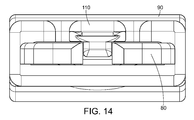
- FIG. 14 is a front view of the clip portion and locking collar portion engaged in a locked.
- FIG. 15 is a side view of the clip portion and locking collar portion engaged in a locked position with the locking collar prominent.
- FIG. 16 is a top perspective view of the clip portion and locking collar portion engaged in a locked position with the locking collar prominent.
- FIG. 17 is a top perspective view of the clip portion and locking collar portion engaged in a locked position with the clip portion prominent.
- FIG. 18 is a top perspective view of the clip portion and locking collar portion moving towards an unlocked position with the clip portion prominent.
- a semi-circular bend with consistent wall thickness is traditionally used in prior art clips.
- the clip of the present invention flexes the legs of the clip towards the closed configuration.
- the bigger the radius of the bend of a clip the stronger the bend point as the bend can take greater stresses/heavier loads.
- the only way to spread the load at the bend of a traditional semi-circular shaped bend is to increase the radius.
- the tear drop shape created by the present invention reduces bulkiness by allowing for a smaller radius at the bend yet still allows the clip to support larger load. Additionally, the bend helps to creates the necessary grip or bite between the two legs by biasing the clip legs towards one another.
- the upper leg 20 and lower leg 30 have parallel overlying portions that create a sandwich type structure to envelop an article such as a belt or belt loop.
- FIG. 1 shows the clip in an open position where the upper leg 20 and lower leg 30 are spread to receive such an article.
- a plurality of longitudinal slats 40 extend from the lower leg 30 .
- a tab 50 extending longitudinally from the upper leg 20 .
- the only way to spread the load of the clip at the bend of a clip is to increase the radius.
- the present invention reduces bulkiness associated with a larger radius in the bend yet still creates the bite between the two legs of the clip by adding mass during the injection molding process to allow for a tear drop shape to form at the bend.
- locking members 80 extend along the sides at the end of the longitudinal slats 40 distal to the lower leg 30 .
- the upper and lower legs 20 and 30 have a plurality apertures providing a plurality of mounting positions 60 to mount a variety of items to the clip.
- FIG. 3 shows the clip portion in the open position wherein the upper leg 20 and lower leg 30 are separated from each other to allow an article to be sandwiched there between, such as a belt.
- FIG. 4 shows the clip portion in the closed position wherein the upper leg 20 and lower leg 30 abut against the article sandwiched there between, such as a belt.
- FIGS. 5-10 various views show the locking collar 90 with an upper and lower portion defines a passageway 100 .
- a pivotable locking member 110 extends outwards from the upper portion of the locking collar 90 and inwards into the passageway 100 .
- FIG. 11 the clip portion A is shown prior to engagement with the locking collar B.
- FIGS. 12-13 the locking collar B is engaged with the clip portion A.
- the locking mechanism of the locking collar B allows the clip portion A and collar portion B to remained joined even when the legs of the clip are in the open position. This ensures that the locking collar B is not lost when attaching or detaching to/from the belt.
- the locking collar 90 is slidably mounted over the plurality of longitudinal slats 40 . This is an action that can easily be taken with one hand.
- the pivotable locking member 110 extends outwards from the upper portion of the locking collar 90 and inwards into the passageway 100 .
- the upper and lower portions of the locking collar 90 slide along the longitudinal slats 40 of the lower leg and the locking members 80 fit in the apertures on the right and left side of the locking collar to form a first open position wherein the tab 50 is not inserted into the locking collar 90 , such that the upper leg 20 may be moved away from the lower leg 30 to engage an article to be secured or sandwiched therebetween.
- the locking collar slides further along the longitudinal slats 40 to a second closed position with the tab 50 extending from the upper leg 30 into the passageway 100 of the locking collar 90 such that the tab 50 extending from the upper leg rests against the pivotable locking member 110 thereby preventing movement of the upper leg 20 away from the lower leg 30 .
- the locking members 80 of the clip portion pass all the way through the locking collar and coordinate to lock the collar 90 from reverse movement along the longitudinal slats 40 of the lower leg 30 . Further, the locking members 80 prevent the locking collar 90 from being removed from the longitudinal slats 40 when in the open position, which keeps the locking collar from being lost during opening and closing of the clip.
- FIG. 18 shows the locking collar 90 as it is slid along the longitudinal slats 40 when the pivotable locking member 110 is raised to release the locking members 80 .
Landscapes
- Engineering & Computer Science (AREA)
- General Engineering & Computer Science (AREA)
- Textile Engineering (AREA)
- Mechanical Engineering (AREA)
- Clamps And Clips (AREA)
Abstract
Description
- This application claims priority to U.S. Provisional Application No. 62/320,038 filed Apr. 8, 2016. The entire contents of the above application are hereby incorporated by reference as though fully set forth herein.
- This invention relates generally to straps and ties employed for binding securing and retaining articles together, and more particularly to releasable locking retaining clips employed for releasably securing articles to belts and the like.
- Retaining clips, ties and like devices have long been provided to bind items together and are well known in the art. Generally, such clips and ties comprise a long strap member that forms a circular loop that connects back to itself, around one or more items to bind them together. They typically incorporate straps with a plurality of grooves for locking engagement with an integrally formed head. Nearly all such designs incorporate a substantially circular shaped loop, which is difficult to secure to a belt such that it lies flat against the user so as to not catch on other structures. While there are many types of straps that form a releaseable loop, many times a special tool is required to release the strap or the method of release is awkward and difficult to perform easily or with one hand only. Similarly, while there are releasable flat loop designs for binding pouches and similar items to a belt, they still use a method of release that is awkward and difficult to perform easily or with one hand only.
- When most clips are attached to an item for carry, the clip is typically fed behind the belt and squeezed shut. However, most clips are not rigid and do not “bite” or grip the belt or vest so it doesn't slide laterally or vertically. As such, it fails to support the weight of the item that it carries. Straps made from flexible material and distort the shape if you pull on them and the item comes away from the belt or vest.
- As such, an object of the present invention is to releasably secure an article to a belt or similar restraint structure using a substantially flat loop and/or clip structure that is releasable, adjustable, reusable and quick and easy to fasten and unfasten. A further object of the present invention is to reduce slack in the clip when it is closed forming a retention structure when everything is closed and locked in order to hold two parts as close together as possible. The point where the material is folded against itself creates a tension structure with enough flexibility that the clip can be attached and detached but the rest of the clip is intended to be rigid so that when it is locked in a closed position there is no flexibility.
- The present invention is a releasable retaining clip for retaining and securing a device to a person or another article, such as a belt. The present invention comprises generally a clip portion comprising (a) a single length of material bent upon itself approximately midway between its ends to provide a tear drop shaped bend from which extends an upper leg and lower leg having parallel overlying portions; (b) a plurality of longitudinal slats extending from the terminal end of the lower leg; (c) locking members extending along the sides at the terminal end of the longitudinal slats; and (d) at least one tab extending longitudinally from the terminal end of the upper leg. A locking collar with an upper and lower portion defines a passageway wherein the locking collar is slidably mounted over the plurality of longitudinal slats. A pivotable locking member extends outwards from the upper portion of the locking collar and inwards into the passageway. The upper and lower portions of the locking collar slide along the longitudinal slats of the lower leg to form a first open position, such that the upper leg may be moved away from the lower leg to engage an article to be secured, to a second closed position with the tab(s) extending from the upper leg into the passageway such that the tab(s) extending from the upper leg rests against the interior of the locking collar, thereby preventing movement of the upper leg away from the lower leg. The pivotable locking member of the locking collar and locking members of the clip also coordinate to lock the collar from reverse movement along the longitudinal slats of the lower leg in both the open and closed positions.
- The upper and lower legs have a plurality apertures providing a plurality of mounting positions to mount a variety of items to the clip. For example, when the clip is attached to a belt, a variety of modular, lightweight, load-carry equipment (MOLLE) may be attached to the clip.
-
FIG. 1 is a side view of the clip portion of the present invention with the clip portion in an open position -
FIG. 2 is a top view of the clip portion of the present invention with the clip portion in a closed position. -
FIG. 3 is a side perspective view of the clip portion of the present invention with the clip portion in an open position. -
FIG. 4 is a side perspective view of the clip portion of the present invention with the clip portion in a closed position. -
FIG. 5 is a front view of the locking collar portion of the present invention. -
FIG. 6 is a top view of the locking collar portion of the present invention. -
FIG. 7 is a side view of the locking collar portion of the present invention. -
FIG. 8 is a rear view of the locking collar portion of the present invention. -
FIG. 9 is a top perspective view of the locking collar portion of the present invention. -
FIG. 10 is a bottom perspective view of the locking collar portion of the present invention. -
FIG. 11 is a top perspective view of the clip portion and locking collar portion prior to engagement. -
FIG. 12 is a top view of the clip portion and locking collar portion engaged in a locked position. -
FIG. 13 is a side view of the clip portion and locking collar portion engaged in a locked position. -
FIG. 14 is a front view of the clip portion and locking collar portion engaged in a locked. -
FIG. 15 is a side view of the clip portion and locking collar portion engaged in a locked position with the locking collar prominent. -
FIG. 16 is a top perspective view of the clip portion and locking collar portion engaged in a locked position with the locking collar prominent. -
FIG. 17 is a top perspective view of the clip portion and locking collar portion engaged in a locked position with the clip portion prominent. -
FIG. 18 is a top perspective view of the clip portion and locking collar portion moving towards an unlocked position with the clip portion prominent. - Turning to
FIG. 1 , the clip portion has a single length of material bent upon itself approximately midway between its ends to provide a tear drop shapedbend 10, which reduces slack in the clip when it is closed creating a retention structure when everything is closed and locked in order to hold theupper leg 20 andlower leg 30 as close together as possible. The tear drop shapedbend 10 is created during the injection molding plastic process. During this process, by adding extra mass and adding a greater radius on the side of the bend connected to the upper leg changes the way the material shrinks and the rate at which it cools. The extra mass and greater radius add more strength by allowing the plastic to cool more slowly and shrink in such a manner that it moves the legs of the clip towards the closed configuration. A semi-circular bend with consistent wall thickness is traditionally used in prior art clips. When making the semi-circular bend using injection molding, as the plastic cools the clip tends to flex towards the open position whereas the extra mass used to create the tear drop bend the clip of the present invention flexes the legs of the clip towards the closed configuration. The bigger the radius of the bend of a clip, the stronger the bend point as the bend can take greater stresses/heavier loads. The only way to spread the load at the bend of a traditional semi-circular shaped bend is to increase the radius. The tear drop shape created by the present invention reduces bulkiness by allowing for a smaller radius at the bend yet still allows the clip to support larger load. Additionally, the bend helps to creates the necessary grip or bite between the two legs by biasing the clip legs towards one another. - The
upper leg 20 andlower leg 30 have parallel overlying portions that create a sandwich type structure to envelop an article such as a belt or belt loop.FIG. 1 shows the clip in an open position where theupper leg 20 andlower leg 30 are spread to receive such an article. A plurality oflongitudinal slats 40 extend from thelower leg 30. Atab 50 extending longitudinally from theupper leg 20. - The only way to spread the load of the clip at the bend of a clip is to increase the radius. The bigger the radius in the bend of the clip, the stronger the hinge point, allowing the clip to withstand greater stresses. The present invention reduces bulkiness associated with a larger radius in the bend yet still creates the bite between the two legs of the clip by adding mass during the injection molding process to allow for a tear drop shape to form at the bend.
- Turning to
FIG. 2 , lockingmembers 80 extend along the sides at the end of thelongitudinal slats 40 distal to thelower leg 30. The upper andlower legs positions 60 to mount a variety of items to the clip.FIG. 3 shows the clip portion in the open position wherein theupper leg 20 andlower leg 30 are separated from each other to allow an article to be sandwiched there between, such as a belt.FIG. 4 shows the clip portion in the closed position wherein theupper leg 20 andlower leg 30 abut against the article sandwiched there between, such as a belt. - Turning to
FIGS. 5-10 , various views show the lockingcollar 90 with an upper and lower portion defines apassageway 100. Apivotable locking member 110 extends outwards from the upper portion of the lockingcollar 90 and inwards into thepassageway 100. When theupper leg 20 andlower leg 30 are in the closed position and is locked with the lockingcollar 90, the clip is rigid and bites or grips the belt/vest so it doesn't slide laterally or vertically; thereby supporting the weight of the item that the clip carries. - Turning to
FIG. 11 , the clip portion A is shown prior to engagement with the locking collar B. InFIGS. 12-13 , the locking collar B is engaged with the clip portion A. The locking mechanism of the locking collar B allows the clip portion A and collar portion B to remained joined even when the legs of the clip are in the open position. This ensures that the locking collar B is not lost when attaching or detaching to/from the belt. - More specifically shown in
FIGS. 15-17 , the lockingcollar 90 is slidably mounted over the plurality oflongitudinal slats 40. This is an action that can easily be taken with one hand. Thepivotable locking member 110 extends outwards from the upper portion of the lockingcollar 90 and inwards into thepassageway 100. The upper and lower portions of the lockingcollar 90 slide along thelongitudinal slats 40 of the lower leg and the lockingmembers 80 fit in the apertures on the right and left side of the locking collar to form a first open position wherein thetab 50 is not inserted into the lockingcollar 90, such that theupper leg 20 may be moved away from thelower leg 30 to engage an article to be secured or sandwiched therebetween. The locking collar slides further along thelongitudinal slats 40 to a second closed position with thetab 50 extending from theupper leg 30 into thepassageway 100 of the lockingcollar 90 such that thetab 50 extending from the upper leg rests against thepivotable locking member 110 thereby preventing movement of theupper leg 20 away from thelower leg 30. The lockingmembers 80 of the clip portion pass all the way through the locking collar and coordinate to lock thecollar 90 from reverse movement along thelongitudinal slats 40 of thelower leg 30. Further, the lockingmembers 80 prevent thelocking collar 90 from being removed from thelongitudinal slats 40 when in the open position, which keeps the locking collar from being lost during opening and closing of the clip. -
FIG. 18 shows the lockingcollar 90 as it is slid along thelongitudinal slats 40 when thepivotable locking member 110 is raised to release the lockingmembers 80. Oncetab 50 is no longer in thelocking collar passageway 100 shown in various other views, theupper leg 20 may be moved away from thelower leg 30. - For the purposes of promoting an understanding of the principles of the invention, reference has been made to the preferred embodiments illustrated in the drawings, and specific language has been used to describe these embodiments. However, this specific language intends no limitation of the scope of the invention, and the invention should be construed to encompass all embodiments that would normally occur to one of ordinary skill in the art. The particular implementations shown and described herein are illustrative examples of the invention and are not intended to otherwise limit the scope of the invention in any way. For the sake of brevity, conventional aspects of the method (and components of the individual operating components of the method) may not be described in detail. Furthermore, the connecting lines, or connectors shown in the various figures presented are intended to represent exemplary functional relationships and/or physical or logical couplings between the various elements. It should be noted that many alternative or additional functional relationships, physical connections or logical connections might be present in a practical device. Moreover, no item or component is essential to the practice of the invention unless the element is specifically described as “essential” or “critical”. Numerous modifications and adaptations will be readily apparent to those skilled in this art without departing from the spirit and scope of the present invention.
Claims (20)
Priority Applications (2)
| Application Number | Priority Date | Filing Date | Title |
|---|---|---|---|
| US15/481,393 US10383430B2 (en) | 2016-04-08 | 2017-04-06 | Releasable retaining clip apparatus and method of use |
| US16/460,188 US10492595B2 (en) | 2016-04-08 | 2019-07-02 | Releasable retaining clip apparatus and method of use |
Applications Claiming Priority (2)
| Application Number | Priority Date | Filing Date | Title |
|---|---|---|---|
| US201662320038P | 2016-04-08 | 2016-04-08 | |
| US15/481,393 US10383430B2 (en) | 2016-04-08 | 2017-04-06 | Releasable retaining clip apparatus and method of use |
Related Child Applications (2)
| Application Number | Title | Priority Date | Filing Date |
|---|---|---|---|
| US16/460,188 Continuation US10492595B2 (en) | 2016-04-08 | 2019-07-02 | Releasable retaining clip apparatus and method of use |
| US16/460,188 Division US10492595B2 (en) | 2016-04-08 | 2019-07-02 | Releasable retaining clip apparatus and method of use |
Publications (2)
| Publication Number | Publication Date |
|---|---|
| US20170290410A1 true US20170290410A1 (en) | 2017-10-12 |
| US10383430B2 US10383430B2 (en) | 2019-08-20 |
Family
ID=59999645
Family Applications (2)
| Application Number | Title | Priority Date | Filing Date |
|---|---|---|---|
| US15/481,393 Active 2037-04-24 US10383430B2 (en) | 2016-04-08 | 2017-04-06 | Releasable retaining clip apparatus and method of use |
| US16/460,188 Active US10492595B2 (en) | 2016-04-08 | 2019-07-02 | Releasable retaining clip apparatus and method of use |
Family Applications After (1)
| Application Number | Title | Priority Date | Filing Date |
|---|---|---|---|
| US16/460,188 Active US10492595B2 (en) | 2016-04-08 | 2019-07-02 | Releasable retaining clip apparatus and method of use |
Country Status (1)
| Country | Link |
|---|---|
| US (2) | US10383430B2 (en) |
Cited By (4)
| Publication number | Priority date | Publication date | Assignee | Title |
|---|---|---|---|---|
| US20180008032A1 (en) * | 2016-07-08 | 2018-01-11 | Amphipod, Inc. | Retainer |
| US10716389B2 (en) | 2018-03-29 | 2020-07-21 | Pure Safety Group, Inc. | Affixable and removable clip |
| USD949546S1 (en) * | 2020-02-24 | 2022-04-26 | Martina Mellace | Fastening device |
| USD1028699S1 (en) * | 2023-08-25 | 2024-05-28 | Ching Man Wong | Clip |
Family Cites Families (16)
| Publication number | Priority date | Publication date | Assignee | Title |
|---|---|---|---|---|
| US308583A (en) * | 1884-11-25 | Ferdinand p | ||
| US1110579A (en) * | 1913-10-28 | 1914-09-15 | Frederick Seeber | Clasp. |
| US3100324A (en) * | 1961-12-13 | 1963-08-13 | Dominick J Tutino | Clothespin with improved self-storing means |
| US5327619A (en) * | 1991-12-26 | 1994-07-12 | Ortega Victor A | Plunger releasable latch |
| US5388313A (en) * | 1993-12-30 | 1995-02-14 | Cameron; Robert W. | Locking clip |
| US5855057A (en) * | 1997-12-29 | 1999-01-05 | National Molding Corp. | Buckle assembly |
| US6357128B1 (en) * | 1998-07-27 | 2002-03-19 | The Brunton Company | Low profile compass with removable protective cover and magnetic bull's eye alignment system |
| US7165371B2 (en) * | 2000-10-13 | 2007-01-23 | Altia Hashimoto Co., Ltd. | Automobile molding and fastener therefor |
| US6698071B1 (en) * | 2002-02-19 | 2004-03-02 | Homax Products, Inc. | Clip systems and methods for sheet materials |
| US6823566B2 (en) * | 2002-04-11 | 2004-11-30 | Logan D. Coffey | Releasable retaining clip apparatus and method |
| AT502863B1 (en) * | 2002-09-11 | 2008-03-15 | Bamed Ag | SCHNULLER BAND CLAMP |
| TW200932610A (en) * | 2008-01-31 | 2009-08-01 | Velo Entpr Co Ltd | Device for connecting the accessories with the seat cushion of bicycle |
| US8336173B2 (en) * | 2008-03-19 | 2012-12-25 | Illinois Tool Works Inc. | Clip assembly |
| US8181847B1 (en) * | 2009-11-16 | 2012-05-22 | Erdie End Caps, Llc | Shipping container provided with external locking clip |
| US9115513B1 (en) * | 2012-12-31 | 2015-08-25 | Yves Cayouette | Securable locking clip |
| US9480328B2 (en) * | 2014-08-08 | 2016-11-01 | Nathaniel D. Stevens | Stabilizing belt clip |
-
2017
- 2017-04-06 US US15/481,393 patent/US10383430B2/en active Active
-
2019
- 2019-07-02 US US16/460,188 patent/US10492595B2/en active Active
Cited By (5)
| Publication number | Priority date | Publication date | Assignee | Title |
|---|---|---|---|---|
| US20180008032A1 (en) * | 2016-07-08 | 2018-01-11 | Amphipod, Inc. | Retainer |
| US10517380B2 (en) * | 2016-07-08 | 2019-12-31 | Amphipod, Inc. | Retainer |
| US10716389B2 (en) | 2018-03-29 | 2020-07-21 | Pure Safety Group, Inc. | Affixable and removable clip |
| USD949546S1 (en) * | 2020-02-24 | 2022-04-26 | Martina Mellace | Fastening device |
| USD1028699S1 (en) * | 2023-08-25 | 2024-05-28 | Ching Man Wong | Clip |
Also Published As
| Publication number | Publication date |
|---|---|
| US10383430B2 (en) | 2019-08-20 |
| US10492595B2 (en) | 2019-12-03 |
| US20190320782A1 (en) | 2019-10-24 |
Similar Documents
| Publication | Publication Date | Title |
|---|---|---|
| US10492595B2 (en) | Releasable retaining clip apparatus and method of use | |
| US10130162B2 (en) | Gear strap | |
| EP3641582B1 (en) | Magnet hook | |
| US9918522B2 (en) | Ratchet belt system and related accessories | |
| US7100249B2 (en) | Buckle | |
| US20160135630A1 (en) | Ratchet belt system and related accessories | |
| US10299576B2 (en) | Strap for retaining articles | |
| US11746822B2 (en) | Modular clipping system | |
| US10070699B2 (en) | Clasp | |
| US10716982B2 (en) | Systems and methods for an adjustable strap system for a golf bag | |
| US20150374089A1 (en) | Luggage carrying device | |
| US11096471B2 (en) | Carrying device | |
| JP5369235B2 (en) | Piping slider | |
| US20150144670A1 (en) | Holders having multiple, adjustable straps | |
| US20140173855A1 (en) | Adjustable strap | |
| US20200138150A1 (en) | A fastening system | |
| US9610485B2 (en) | Golf bag clamping apparatus | |
| KR101746116B1 (en) | Multipurpose strap | |
| JP2019063058A (en) | Traction tool for carry bag | |
| US20120234878A1 (en) | Quick-release attachment mechanism for load-bearing carriages |
Legal Events
| Date | Code | Title | Description |
|---|---|---|---|
| STPP | Information on status: patent application and granting procedure in general |
Free format text: RESPONSE TO NON-FINAL OFFICE ACTION ENTERED AND FORWARDED TO EXAMINER |
|
| STPP | Information on status: patent application and granting procedure in general |
Free format text: NOTICE OF ALLOWANCE MAILED -- APPLICATION RECEIVED IN OFFICE OF PUBLICATIONS |
|
| AS | Assignment |
Owner name: EDGE-WORKS MANUFACTURING COMPANY, NORTH CAROLINA Free format text: ASSIGNMENT OF ASSIGNORS INTEREST;ASSIGNORS:EVANS, SCOTT V.;TOMCZAK, NICHOLAS R.;REEL/FRAME:049650/0334 Effective date: 20190702 |
|
| STPP | Information on status: patent application and granting procedure in general |
Free format text: PUBLICATIONS -- ISSUE FEE PAYMENT VERIFIED |
|
| STCF | Information on status: patent grant |
Free format text: PATENTED CASE |
|
| MAFP | Maintenance fee payment |
Free format text: PAYMENT OF MAINTENANCE FEE, 4TH YR, SMALL ENTITY (ORIGINAL EVENT CODE: M2551); ENTITY STATUS OF PATENT OWNER: SMALL ENTITY Year of fee payment: 4 |