US20170140887A1 - Port controller with power contract negotiation capability - Google Patents
Port controller with power contract negotiation capability Download PDFInfo
- Publication number
- US20170140887A1 US20170140887A1 US15/350,609 US201615350609A US2017140887A1 US 20170140887 A1 US20170140887 A1 US 20170140887A1 US 201615350609 A US201615350609 A US 201615350609A US 2017140887 A1 US2017140887 A1 US 2017140887A1
- Authority
- US
- United States
- Prior art keywords
- power
- power supply
- port
- usb
- port controller
- Prior art date
- Legal status (The legal status is an assumption and is not a legal conclusion. Google has not performed a legal analysis and makes no representation as to the accuracy of the status listed.)
- Granted
Links
Images


Classifications
-
- H—ELECTRICITY
- H01—ELECTRIC ELEMENTS
- H01H—ELECTRIC SWITCHES; RELAYS; SELECTORS; EMERGENCY PROTECTIVE DEVICES
- H01H47/00—Circuit arrangements not adapted to a particular application of the relay and designed to obtain desired operating characteristics or to provide energising current
-
- G—PHYSICS
- G01—MEASURING; TESTING
- G01R—MEASURING ELECTRIC VARIABLES; MEASURING MAGNETIC VARIABLES
- G01R19/00—Arrangements for measuring currents or voltages or for indicating presence or sign thereof
- G01R19/165—Indicating that current or voltage is either above or below a predetermined value or within or outside a predetermined range of values
- G01R19/16566—Circuits and arrangements for comparing voltage or current with one or several thresholds and for indicating the result not covered by subgroups G01R19/16504, G01R19/16528, G01R19/16533
- G01R19/16576—Circuits and arrangements for comparing voltage or current with one or several thresholds and for indicating the result not covered by subgroups G01R19/16504, G01R19/16528, G01R19/16533 comparing DC or AC voltage with one threshold
-
- G—PHYSICS
- G01—MEASURING; TESTING
- G01R—MEASURING ELECTRIC VARIABLES; MEASURING MAGNETIC VARIABLES
- G01R31/00—Arrangements for testing electric properties; Arrangements for locating electric faults; Arrangements for electrical testing characterised by what is being tested not provided for elsewhere
- G01R31/40—Testing power supplies
-
- G—PHYSICS
- G06—COMPUTING OR CALCULATING; COUNTING
- G06F—ELECTRIC DIGITAL DATA PROCESSING
- G06F1/00—Details not covered by groups G06F3/00 - G06F13/00 and G06F21/00
- G06F1/26—Power supply means, e.g. regulation thereof
- G06F1/266—Arrangements to supply power to external peripherals either directly from the computer or under computer control, e.g. supply of power through the communication port, computer controlled power-strips
-
- H—ELECTRICITY
- H01—ELECTRIC ELEMENTS
- H01R—ELECTRICALLY-CONDUCTIVE CONNECTIONS; STRUCTURAL ASSOCIATIONS OF A PLURALITY OF MUTUALLY-INSULATED ELECTRICAL CONNECTING ELEMENTS; COUPLING DEVICES; CURRENT COLLECTORS
- H01R24/00—Two-part coupling devices, or either of their cooperating parts, characterised by their overall structure
- H01R24/28—Coupling parts carrying pins, blades or analogous contacts and secured only to wire or cable
-
- H—ELECTRICITY
- H01—ELECTRIC ELEMENTS
- H01R—ELECTRICALLY-CONDUCTIVE CONNECTIONS; STRUCTURAL ASSOCIATIONS OF A PLURALITY OF MUTUALLY-INSULATED ELECTRICAL CONNECTING ELEMENTS; COUPLING DEVICES; CURRENT COLLECTORS
- H01R24/00—Two-part coupling devices, or either of their cooperating parts, characterised by their overall structure
- H01R24/60—Contacts spaced along planar side wall transverse to longitudinal axis of engagement
-
- H—ELECTRICITY
- H02—GENERATION; CONVERSION OR DISTRIBUTION OF ELECTRIC POWER
- H02J—ELECTRIC POWER NETWORKS; CIRCUIT ARRANGEMENTS OR SYSTEMS FOR SUPPLYING OR DISTRIBUTING ELECTRIC POWER; SYSTEMS FOR STORING ELECTRIC ENERGY
- H02J7/00—Circuit arrangements for charging or discharging batteries or for supplying loads from batteries
- H02J7/60—Circuit arrangements for charging or discharging batteries or for supplying loads from batteries including safety or protection arrangements
- H02J7/62—Circuit arrangements for charging or discharging batteries or for supplying loads from batteries including safety or protection arrangements against overcurrent
-
- H—ELECTRICITY
- H02—GENERATION; CONVERSION OR DISTRIBUTION OF ELECTRIC POWER
- H02J—ELECTRIC POWER NETWORKS; CIRCUIT ARRANGEMENTS OR SYSTEMS FOR SUPPLYING OR DISTRIBUTING ELECTRIC POWER; SYSTEMS FOR STORING ELECTRIC ENERGY
- H02J7/00—Circuit arrangements for charging or discharging batteries or for supplying loads from batteries
- H02J7/60—Circuit arrangements for charging or discharging batteries or for supplying loads from batteries including safety or protection arrangements
- H02J7/64—Circuit arrangements for charging or discharging batteries or for supplying loads from batteries including safety or protection arrangements against overvoltage
-
- H—ELECTRICITY
- H01—ELECTRIC ELEMENTS
- H01R—ELECTRICALLY-CONDUCTIVE CONNECTIONS; STRUCTURAL ASSOCIATIONS OF A PLURALITY OF MUTUALLY-INSULATED ELECTRICAL CONNECTING ELEMENTS; COUPLING DEVICES; CURRENT COLLECTORS
- H01R2107/00—Four or more poles
-
- H—ELECTRICITY
- H02—GENERATION; CONVERSION OR DISTRIBUTION OF ELECTRIC POWER
- H02J—ELECTRIC POWER NETWORKS; CIRCUIT ARRANGEMENTS OR SYSTEMS FOR SUPPLYING OR DISTRIBUTING ELECTRIC POWER; SYSTEMS FOR STORING ELECTRIC ENERGY
- H02J7/00—Circuit arrangements for charging or discharging batteries or for supplying loads from batteries
- H02J7/60—Circuit arrangements for charging or discharging batteries or for supplying loads from batteries including safety or protection arrangements
- H02J7/61—Circuit arrangements for charging or discharging batteries or for supplying loads from batteries including safety or protection arrangements against overcharge
-
- H—ELECTRICITY
- H02—GENERATION; CONVERSION OR DISTRIBUTION OF ELECTRIC POWER
- H02J—ELECTRIC POWER NETWORKS; CIRCUIT ARRANGEMENTS OR SYSTEMS FOR SUPPLYING OR DISTRIBUTING ELECTRIC POWER; SYSTEMS FOR STORING ELECTRIC ENERGY
- H02J7/00—Circuit arrangements for charging or discharging batteries or for supplying loads from batteries
- H02J7/60—Circuit arrangements for charging or discharging batteries or for supplying loads from batteries including safety or protection arrangements
- H02J7/63—Circuit arrangements for charging or discharging batteries or for supplying loads from batteries including safety or protection arrangements against overdischarge
Definitions
- USB universal serial bus
- Traditional universal serial bus (USB) systems which include USB cables and connectors, are typically used to transfer data between multiple electronic devices and to provide low-level power (e.g., at voltage levels of 5 V or less) from a source device to a sink device.
- low-level power transfer enables a small, low-power device—such as a smartphone—to be charged from the battery of a larger device, such as a notebook.
- a small, low-power device such as a smartphone
- a larger device such as a notebook.
- such low-level power is insufficient to charge larger devices with greater power needs, such as the notebook itself.
- barreljack or “power brick”
- Newer USB Type C systems with power delivery (PD) capability take the traditional USB's power supply capabilities a step further by enabling the sourcing and sinking of power at greater levels (e.g., with voltages greater than 5 V).
- PD power delivery
- appropriately-configured notebooks can use such newer USB systems both to charge smaller devices (as with traditional USB systems) and to be charged from mains power (not possible with traditional USB systems).
- Such newer USB Type C systems with PD capability eliminate the need for bulky and inconvenient barreljack connections and equipment.
- At least some embodiments are directed to an electronic device port system comprising a first device configured to negotiate power supply contracts from a power source via a universal serial bus (USB) cable.
- the system also comprises a second device configured to negotiate power supply contracts from the power source via the USB cable when the first device is unable to negotiate power supply contracts from the power source.
- the second device is configured to activate a switch after the second device negotiates a power supply contract with the power source.
- the switch is configured to permit the provision of power from the power source to a battery system of the electronic device per the negotiated power supply contract.
- USB cable is a USB Type C cable with power delivery (PD) capability
- the first device comprises a Type C port manager
- the second device comprises a Type C port controller
- the second device is configured to determine that the first device is unable to negotiate power supply contracts based on a rail voltage supply that powers the first device
- the system is configured to source power to another electronic device
- the switch comprises a metal oxide semiconductor field effect transistor (MOSFET);
- MOSFET metal oxide semiconductor field effect transistor
- the second device is configured to negotiate power supply contracts from the power source via a configuration channel (CC) in the USB cable; wherein the power supplied per the negotiated power supply contract is provided to the switch via a pair of dedicated power lines in the USB cable; wherein, upon receipt of the power per the negotiated power supply contract, the battery system powers the first device, and wherein the second device is configured to relinquish power supply contract negotiations to the first device upon a determination that the first device is
- At least some embodiments are directed to a system comprising a battery system and a DC-to-DC converter coupled to the battery system and configured to provide a rail voltage supply.
- the system also comprises a port manager powered by the rail voltage supply and configured to negotiate power contracts with a power supply on behalf of the system via a universal serial bus (USB) cable.
- the system further includes a port controller powered by the power supply via the USB cable and configured to negotiate power contracts with the power supply on behalf of the system via the USB cable when the port controller detects that the port manager is powered below a threshold level, the battery system is powered below another threshold level, or both.
- the port controller is configured to determine that the port manager is powered below the threshold level via an inter-integrated circuit (I2C) connection; wherein the port controller is configured to determine that the battery system is powered below the another threshold level via the rail voltage supply; wherein the USB cable is a USB Type C cable with power delivery (PD) capability; wherein the power supply is a mains power adapter; wherein the power supply is a portable electronic device; wherein the system comprises a second port controller configured to negotiate power contracts with the power supply on behalf of the system via the USB cable when the second port controller detects that the port manager is powered below the threshold level, the battery system is powered below the another threshold level, or both, and wherein the second port controller negotiates a power contract with the power supply only when the port controller provides a permission indication to the second port controller.
- I2C inter-integrated circuit
- At least some embodiments are directed to a method comprising using a device to negotiate power supply contracts from a power source via a data and power transmission cable, determining that the device is not receiving power meeting a minimum threshold, reviewing power supply options received from the power source via the data and power transmission cable, selecting one of the received power supply options, providing the power source with an indication of the selection, receiving power from the power source in accordance with the selection, and establishing an electrical pathway between the power source and a battery system.
- One or more such embodiments may be supplemented using one or more of the following concepts, in any order and in any combination: wherein the device comprises a USB Type C port manager; wherein establishing the electrical pathway between the power source and the battery system comprises closing a p-type metal oxide semiconductor field effect transistor (MOSFET) switch and closing an n-type MOSFET serially coupled to the p-type MOSFET.
- MOSFET metal oxide semiconductor field effect transistor
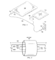
- FIG. 1 is a perspective view of an illustrative electronic device configured to source power from mains power via a USB Type C system with PD capability and further configured to sink power to another electronic device via the same USB system.
- FIG. 2 is an illustrative, schematic diagram of at least some of the contents of a cable in a USB Type C system with PD capability.
- FIG. 3 is a schematic block diagram of an illustrative electronic device port system that is compatible with a USB Type C system with PD capability.
- FIG. 4 is a flow diagram of an illustrative process in accordance with various embodiments.
- FIG. 5 is an illustrative, schematic block diagram of the port controller depicted in FIG. 3 .
- the USB ports e.g., ports in a notebook and in a USB wall adapter, or ports in a notebook and in a smaller electronic device
- the source e.g., mains power USB adapter
- the sink e.g., notebook USB port system
- Such power negotiation is considered to be a higher-order task and is thus typically performed by an embedded controller (and/or by another processor, such as a system-on-chip (SoC) or application processor (AP)).
- SoC system-on-chip
- AP application processor
- At least some of the embodiments described herein are directed to a USB Type C/PD-compatible electronic device port system that is configured to execute power negotiations when the embedded controller (or other processor) that is typically responsible for power negotiations is temporarily incapacitated. More specifically, in some cases, the electronic device battery system may be completely discharged and, as a result, the embedded controller inside the electronic device port system may be unavailable to negotiate a power contract with an adapter that is capable of supplying power to the electronic device. In such situations, a port controller—which is typically not responsible for higher-level functions like power contract negotiations—determines that the embedded controller is incapacitated and takes over power negotiation duties until the embedded controller is powered again.
- the port controller relinquishes its power contract negotiation duties back to the embedded controller. This technique reduces the amount of time required to negotiate a power contract for the electronic device and reduces downtime for the embedded controller and for the electronic device in general.
- FIG. 1 is a perspective view of an illustrative electronic device configured to source power from mains power via a USB Type C system with PD capability and further configured to sink power to another electronic device via the same USB system.
- FIG. 1 depicts an electronic device 100 adapted for coupling to a USB Type C/PD cable 104 having connectors 102 , 106 disposed on opposing ends of the cable.
- the electronic device 100 may take the form of any of a variety of other battery-powered electronic devices, such as and without limitation, laptops, tablets (e.g., IPADs®), smartphones, portable music players, and any other battery-powered electronic device compatible with both USB Type C and PD specifications.
- the contents of the USB cable 104 are depicted and described in greater detail with respect to FIG. 2 .
- the electronic device 100 comprises a USB Type C/PD port 116 to which the connector 102 may couple.
- the connector 106 at the opposing end of the USB cable 104 may couple to a variety of devices.
- the connector 106 may couple to a mains power adapter 108 that plugs into and sinks power from a wall outlet 110 .
- a port system within the electronic device 100 communicates with the mains power adapter 108 to negotiate a power contract whereby the mains power adapter 108 sources power to the port system and, more generally, to the entire electronic device 100 .
- the connector 106 couples to a USB Type C/PD port 114 in an electronic device 112 .
- FIG. 1 depicts the electronic device 112 as a tablet, but the electronic device 112 is any portable, battery-operated electronic device capable of being charged by the electronic device 102 via the USB Type C/PD cable 104 .
- the USB port system in the electronic device 102 communicates with the USB port system within the electronic device 112 to negotiate a power contract whereby the electronic device 102 sources power to the electronic device 112 .
- USB Type C/PD port systems in the electronic devices depicted in FIG. 1 for instance, in the electronic device 100 —comprise Type C port managers (TCPMs, such as embedded controllers, systems on chip and/or application processors) that handle higher-level operations for the port system, such as power contract negotiations with other electronic devices via the USB Type C/PD cable.
- TCPMs Type C port managers
- Each port manager manages one or more port controllers, with each port controller typically controlling a single port.
- a port manager may manage multiple port controllers.
- Port controllers typically handle lower-level operations for corresponding ports, such as routing and managing incoming power and data, outgoing power and data, etc.
- Port managers are powered directly with voltage supply rails received directly or indirectly from the electronic device battery.
- the port manager When the battery is dead or the battery charge drops below a threshold value, the port manager is no longer able to perform power contract negotiations with other electronic devices, and it goes offline because its power level drops below a threshold value.
- the port controller for a port managed by the port manager may “step up” and take over power contract negotiation duties for the port manager.
- the port controller may establish an electrical pathway between the external electronic device and the dead battery that is responsible for supplying power to the port manager. In this way, the port manager is powered up again, and the port controller then relinquishes its power contract negotiation duties back to the port manager.
- the controllers may determine among themselves which controller will handle power contract negotiations.
- FIG. 2 is an illustrative, schematic diagram of at least some of the conductors within the USB Type C/PD cable 104 (the cable 104 is also depicted in FIG. 1 ).
- the cable 104 includes a configuration channel (CC) 200 , a pair of power lines (V BUS ) 202 A and 202 B, and a plurality of data lines 204 .
- the CC line 200 may be dedicated to communications relating to power contract negotiations.
- the power lines 202 A, 202 B may be dedicated to sourcing and/or sinking power.
- the data lines 204 may be dedicated to transferring data (e.g., text-based files, audio files, video files).
- the USB cable 104 and its connectors (shown in FIG. 1 but omitted from FIG. 2 ) support both the Type C and PD specifications.
- the scope of disclosure is not limited to implementing the disclosed concepts in the USB Type C/PD context, however, and the disclosed concepts may be extended to any current or future USB specification(s) in
- FIG. 3 is a schematic block diagram of an illustrative electronic device port system that supports the USB Type C/PD specifications (or, alternatively, suitable USB specification(s) that enable power contract negotiations).
- FIG. 3 depicts a port system 300 that includes a port controller 302 ; a Type C power manager (TCPM) 304 that comprises an embedded controller (EC) 308 and/or a system-on-chip (SoC) and/or application processor (AP) 306 ; a battery system 310 ; a DC/DC converter 312 ; another DC/DC converter 314 ; an inbound power line 316 ; an outbound power line 318 ; a node 320 connecting the battery system 310 and the DC/DC converters 312 , 314 ; a node 322 coupling EC 308 , DC/DC converter 314 , the SoC/AP 306 , and the port controller 302 ; a node 324 coupling the SoC/AP 306 , the EC 308 , and the
- the port controller 302 comprises any suitable logic (e.g., hardware, software and/or firmware) that enables the port controller 302 to perform the various actions attributed herein to the port controller 302 .
- the SoC/AP 306 and the EC 308 comprise suitable logic (e.g., hardware, software, and/or firmware) that enables the SoC/AP 306 and the EC 308 to perform the various actions attributed herein to the SoC/AP 306 and the EC 308 .
- the battery system 310 may receive voltage and current at varying levels on the inbound power line 318 (e.g., 9 V and 2 A; 12 V and 1 A).
- the voltage level on the node 320 may be at any of a variety of levels (e.g., 9 V).
- the DC/DC converter 312 may step the voltage on node 320 down to, e.g., 5 V on outbound power line 316 .
- the outbound power line 316 may be used to source power from the battery system 310 to other electronic devices via MOSFETs 328 , 330 .
- the DC/DC converter 314 may step the voltage on node 320 down to, e.g., 3.3 V on voltage rail supply 322 .
- the voltage rail supply 322 is provided to the EC 308 via pin V DD , to the SoC/AP 306 via pin V DD , and to the port controller 302 via pin V DD .
- Node 324 couples to the SoC/AP 306 via the inter-integrated circuit (I2C) pins, to the EC 308 via the I2C pins, and to the port controller 302 via the I2C pins, thus enabling these three components to communicate with each other.
- the port controller 302 couples to the CC line 200 via the CC pin and the V BUS power line via the V BUS and GND pins.
- the port controller 302 outputs the MOSFET controls 336 - 339 via the switch control pins.
- the process 400 begins with monitoring the port controller rail voltage supply (block 402 ) and determining whether the rail voltage supply is available (block 404 ).
- the port controller 302 may perform this step.
- the port controller 302 monitors the rail voltage supply 322 on the V DD pin for a supply voltage that drops below a predetermined threshold.
- the port controller 302 may include or be coupled to a voltage comparator that compares the rail voltage supply 322 to a reference voltage (e.g., the predetermined threshold) and uses the output of the voltage comparator to determine the status of the rail voltage supply 322 .
- the TCPM 304 which is powered only by the rail voltage supply—is offline.
- the TCPM 304 and, more specifically, its constituent components, the SoC/AP 306 and/or the EC 308 —are unable to negotiate power contracts contracts (or, if a previous contract has been negotiated, these components are unable to negotiate a new power contract when necessary).
- the port controller 302 may monitor the status of the SoC/AP 306 and/or the EC 308 directly via the I2C node 324 (for example and without limitation, through periodic heartbeat signals sent by the SoC/AP 306 and/or the EC 308 , or through responses to periodic heartbeat signals sent by the port controller 302 ). If attempts to communicate with either of these components are unsuccessful, the port controller 302 may conclude that they are insufficiently powered (i.e., below a predetermined threshold) and are thus offline. If the component among the SoC/AP 306 and the EC 308 that is responsible for negotiating power contracts is offline, then the TCPM 304 is considered to be unable to negotiate power contracts.
- the port controller 302 determines that the SoC/AP 306 or the EC 308 (whichever is responsible for negotiating power contracts) is offline, the port controller 302 determines that the TCPM is likely offline for power contract negotiation purposes (block 406 ).
- the illustrative method 400 may continue by requesting and reviewing the power source options presented by another, external electronic device via the CC pin (block 408 ). This step may be performed, for example, by the port controller 302 .
- the port controller 302 upon determining that the TCPM 304 , which is usually responsible for power contract negotiations, is offline—communicates with the electronic device to which the port system 300 is coupled via the CC 200 to begin negotiations for receiving power via the CC 200 .
- the CC 200 may couple to a mains power adapter, such as the adapter 108 depicted in FIG. 1 .
- the CC 200 may couple to a laptop computer or to a mains power adapter. Regardless of the nature of the external electronic device to which the CC 200 couples, it is assumed that the electronic device is compatible with USB Type C/PD specifications. Accordingly, the port controller 302 and the external electronic device negotiate for a power contract via the CC 200 . Specifically, the electronic device—in some embodiments, upon request—presents the port controller 302 with a plurality of power supply options from which to choose. For instance, the electronic device may present the port controller 302 a first voltage at a first current, a second voltage at the first current, a third voltage at a second current, etc.
- the method 400 subsequently comprises selecting a target power source option via the CC 200 (block 410 ).
- the port controller 302 may perform this step.
- the port controller 302 may be pre-programmed with specific voltage and current combinations that are acceptable for charging the battery system 310 .
- the port controller 302 selects an option from the power options offered by the external electronic device to which the CC 200 couples based on the preferences pre-programmed into the port controller 302 . If a preferred voltage and current combination is not offered via the CC 200 , the port controller 302 may choose the option that most closely approximates the preferred or acceptable options pre-programmed into the port controller 302 .
- the port controller 302 may notify the electronic device of its selection via the CC 200 (block 412 ).
- the steps 408 , 410 , and 412 thus are parts of the power contract negotiation process.
- the process 400 next comprises receiving a ready message from the electronic device via the CC 200 when the electronic device is ready to act as a power supply to the battery system 310 (block 414 ).
- the port controller 302 receives the ready message from the external electronic device via the CC 200 .
- the port system 300 may begin sinking power from the external electronic device.
- the port controller 302 activates the MOSFETs 332 , 334 using MOSFET controls 338 , 339 (block 416 ).
- the MOSFET controls 338 , 339 comprise connections to the gates and sources of the MOSFETs via which V gs voltages may be applied that activate the MOSFETs 332 , 334 .
- the port controller 302 may also ensure that the MOSFETs 328 , 330 are off at this time using the MOSFET controls 336 , 337 .
- Activating the MOSFETs 332 , 334 facilitates sinking power from the external electronic device, through the V BUS power lines 202 A, 202 B, through the inbound power line 318 , and to the battery system 310 .
- the battery system 310 is charged and, by extension, the TCPM 304 is powered via the DC/DC converter 314 (block 418 ).
- the port controller 302 relinquishes its power contract negotiation duties to the TCPM 304 (and, more specifically, to whichever of the SoC/AP 306 and/or EC 308 is typically responsible for negotiating power contracts) (block 420 ).
- the port controller 302 may relinquish these duties using, e.g., one or more messages transmitted via the I2C pin and node 324 .
- the port controllers may communicate with each other via the GPIO 326 so that efforts to power the battery system 310 are not duplicated by the multiple port controllers.
- a first port controller may send a permission indication to a second port controller indicating that the second port controllers may or may not engage in negotiating power contracts and manipulating MOSFET switches to create an electrical pathway between power source and battery system.
- one of the port controllers may be designated as a master port controller and the remaining port controllers may be designated as slave port controllers, meaning that the master port controller uses permission indications to dictate which port controller will negotiate power contracts.
- This designation may occur, e.g., as a pre-programmed feature or at the direction of the port manager (e.g., TCPM 304 of FIG. 3 ).
- the method 400 may be modified as desired, including by adding, deleting, modifying, or rearranging one or more steps.
- FIG. 5 is an illustrative, schematic block diagram of the port controller 302 depicted in FIG. 3 .
- the port controller 302 includes a power management component 500 ; an overvoltage/overcurrent protection monitor 502 ; analog drivers 504 ; and control logic 506 .
- the control logic 506 includes executable code 508 (e.g., software, firmware) and any other hardware necessary to perform the actions attributed herein to the control logic 506 .
- the power management component 500 receives the V BUS power line 202 A, V 00 322 , and ground line 202 B.
- the V BUS power line 202 A is also provided to the monitor 502 , which, in turn, provides an enable signal to analog drivers 504 .
- Analog drivers 504 issue MOSFET controls 336 - 339 , which are used to activate and deactivate the MOSFETs 328 , 330 , 332 , and 334 ( FIG. 3 ).
- the control logic 506 receives CC 200 and GPIO 326 . Further, the control logic 506 couples to the power management component 500 via bus 510 , to the monitor 502 via bus 512 , and to analog drivers 504 via bus 514 .
- the control logic 506 negotiates power contracts via CC 200 .
- the control logic 506 also manages the actions of the power management component 500 , the monitor 502 , and the analog drivers 504 .
- the power management 500 receives power via power lines 202 A, 202 B and communicates information about the received power to the control logic 506 via bus 510 .
- the analog drivers 504 activate and deactivate the MOSFETs using MOSFET controls 336 - 339 at the direction of the control logic 506 , depending on whether a power contract has been successfully negotiated. If an excessive amount of voltage or current is supplied (e.g., voltage or current exceeding defined thresholds), the monitor 502 signals the analog drivers 504 via bus 516 to disable the MOSFETs 332 , 334 ( FIG. 3 ). This action protects the port system from the deleterious effects of overvoltage and overcurrent situations.
- the control logic 506 issues and receives communications from the control logic of other port controllers via GPIO 326 .
Landscapes
- Engineering & Computer Science (AREA)
- General Engineering & Computer Science (AREA)
- Theoretical Computer Science (AREA)
- Physics & Mathematics (AREA)
- General Physics & Mathematics (AREA)
- Power Engineering (AREA)
- Computer Hardware Design (AREA)
- Power Sources (AREA)
- Direct Current Feeding And Distribution (AREA)
Abstract
Description
- The present application claims priority to U.S. Provisional Patent Application No. 62/254,936, which was filed on Nov. 13, 2015, is titled “Type-C Port Controller With Temporary Sink Policy Engine,” and is hereby incorporated herein by reference in its entirety.
- Traditional universal serial bus (USB) systems, which include USB cables and connectors, are typically used to transfer data between multiple electronic devices and to provide low-level power (e.g., at voltage levels of 5 V or less) from a source device to a sink device. Such low-level power transfer enables a small, low-power device—such as a smartphone—to be charged from the battery of a larger device, such as a notebook. However, such low-level power is insufficient to charge larger devices with greater power needs, such as the notebook itself. Thus, such larger devices are relegated to using traditional barreljack (or “power brick”) connections to mains power supplies (“wall outlets”).
- Newer USB Type C systems with power delivery (PD) capability take the traditional USB's power supply capabilities a step further by enabling the sourcing and sinking of power at greater levels (e.g., with voltages greater than 5 V). Thus, for example, appropriately-configured notebooks can use such newer USB systems both to charge smaller devices (as with traditional USB systems) and to be charged from mains power (not possible with traditional USB systems). Such newer USB Type C systems with PD capability eliminate the need for bulky and inconvenient barreljack connections and equipment.
- At least some embodiments are directed to an electronic device port system comprising a first device configured to negotiate power supply contracts from a power source via a universal serial bus (USB) cable. The system also comprises a second device configured to negotiate power supply contracts from the power source via the USB cable when the first device is unable to negotiate power supply contracts from the power source. The second device is configured to activate a switch after the second device negotiates a power supply contract with the power source. The switch is configured to permit the provision of power from the power source to a battery system of the electronic device per the negotiated power supply contract. One or more such embodiments may be supplemented using one or more of the following concepts, in any order and in any combination: wherein the USB cable is a USB Type C cable with power delivery (PD) capability; wherein the first device comprises a Type C port manager; wherein the second device comprises a Type C port controller; wherein the second device is configured to determine that the first device is unable to negotiate power supply contracts based on a rail voltage supply that powers the first device; wherein the system is configured to source power to another electronic device; wherein the switch comprises a metal oxide semiconductor field effect transistor (MOSFET); wherein the second device is configured to negotiate power supply contracts from the power source via a configuration channel (CC) in the USB cable; wherein the power supplied per the negotiated power supply contract is provided to the switch via a pair of dedicated power lines in the USB cable; wherein, upon receipt of the power per the negotiated power supply contract, the battery system powers the first device, and wherein the second device is configured to relinquish power supply contract negotiations to the first device upon a determination that the first device is able to negotiate power supply contracts from the power source.
- At least some embodiments are directed to a system comprising a battery system and a DC-to-DC converter coupled to the battery system and configured to provide a rail voltage supply. The system also comprises a port manager powered by the rail voltage supply and configured to negotiate power contracts with a power supply on behalf of the system via a universal serial bus (USB) cable. The system further includes a port controller powered by the power supply via the USB cable and configured to negotiate power contracts with the power supply on behalf of the system via the USB cable when the port controller detects that the port manager is powered below a threshold level, the battery system is powered below another threshold level, or both. One or more such embodiments may be supplemented using one or more of the following concepts, in any order and in any combination: wherein the port controller is configured to determine that the port manager is powered below the threshold level via an inter-integrated circuit (I2C) connection; wherein the port controller is configured to determine that the battery system is powered below the another threshold level via the rail voltage supply; wherein the USB cable is a USB Type C cable with power delivery (PD) capability; wherein the power supply is a mains power adapter; wherein the power supply is a portable electronic device; wherein the system comprises a second port controller configured to negotiate power contracts with the power supply on behalf of the system via the USB cable when the second port controller detects that the port manager is powered below the threshold level, the battery system is powered below the another threshold level, or both, and wherein the second port controller negotiates a power contract with the power supply only when the port controller provides a permission indication to the second port controller.
- At least some embodiments are directed to a method comprising using a device to negotiate power supply contracts from a power source via a data and power transmission cable, determining that the device is not receiving power meeting a minimum threshold, reviewing power supply options received from the power source via the data and power transmission cable, selecting one of the received power supply options, providing the power source with an indication of the selection, receiving power from the power source in accordance with the selection, and establishing an electrical pathway between the power source and a battery system. One or more such embodiments may be supplemented using one or more of the following concepts, in any order and in any combination: wherein the device comprises a USB Type C port manager; wherein establishing the electrical pathway between the power source and the battery system comprises closing a p-type metal oxide semiconductor field effect transistor (MOSFET) switch and closing an n-type MOSFET serially coupled to the p-type MOSFET.
- For a detailed description of various examples, reference will now be made to the accompanying drawings in which:
-
FIG. 1 is a perspective view of an illustrative electronic device configured to source power from mains power via a USB Type C system with PD capability and further configured to sink power to another electronic device via the same USB system. -
FIG. 2 is an illustrative, schematic diagram of at least some of the contents of a cable in a USB Type C system with PD capability. -
FIG. 3 is a schematic block diagram of an illustrative electronic device port system that is compatible with a USB Type C system with PD capability. -
FIG. 4 is a flow diagram of an illustrative process in accordance with various embodiments. -
FIG. 5 is an illustrative, schematic block diagram of the port controller depicted inFIG. 3 . - To facilitate the sourcing and sinking of higher-than-traditional power levels via a USB Type C with PD capability, the USB ports (e.g., ports in a notebook and in a USB wall adapter, or ports in a notebook and in a smaller electronic device) must negotiate a power contract, meaning that the source (e.g., mains power USB adapter) must offer the sink (e.g., notebook USB port system) one or more power levels to choose from, and the sink must choose from among the available power levels and start sinking the power. Such power negotiation is considered to be a higher-order task and is thus typically performed by an embedded controller (and/or by another processor, such as a system-on-chip (SoC) or application processor (AP)).
- At least some of the embodiments described herein are directed to a USB Type C/PD-compatible electronic device port system that is configured to execute power negotiations when the embedded controller (or other processor) that is typically responsible for power negotiations is temporarily incapacitated. More specifically, in some cases, the electronic device battery system may be completely discharged and, as a result, the embedded controller inside the electronic device port system may be unavailable to negotiate a power contract with an adapter that is capable of supplying power to the electronic device. In such situations, a port controller—which is typically not responsible for higher-level functions like power contract negotiations—determines that the embedded controller is incapacitated and takes over power negotiation duties until the embedded controller is powered again. Once the embedded controller is powered again and is able to conduct power contract negotiations, the port controller relinquishes its power contract negotiation duties back to the embedded controller. This technique reduces the amount of time required to negotiate a power contract for the electronic device and reduces downtime for the embedded controller and for the electronic device in general.
-
FIG. 1 is a perspective view of an illustrative electronic device configured to source power from mains power via a USB Type C system with PD capability and further configured to sink power to another electronic device via the same USB system. Specifically,FIG. 1 depicts anelectronic device 100 adapted for coupling to a USB Type C/PD cable 104 havingconnectors electronic device 100 as a notebook computer is merely illustrative; in other embodiments, theelectronic device 100 may take the form of any of a variety of other battery-powered electronic devices, such as and without limitation, laptops, tablets (e.g., IPADs®), smartphones, portable music players, and any other battery-powered electronic device compatible with both USB Type C and PD specifications. The contents of theUSB cable 104 are depicted and described in greater detail with respect toFIG. 2 . - The
electronic device 100 comprises a USB Type C/PD port 116 to which theconnector 102 may couple. Theconnector 106 at the opposing end of theUSB cable 104 may couple to a variety of devices. For instance, theconnector 106 may couple to amains power adapter 108 that plugs into and sinks power from awall outlet 110. In this configuration, a port system within theelectronic device 100 communicates with themains power adapter 108 to negotiate a power contract whereby themains power adapter 108 sources power to the port system and, more generally, to the entireelectronic device 100. In another configuration, theconnector 106 couples to a USB Type C/PD port 114 in anelectronic device 112. (In some embodiments, theUSB cable 104 may be hard-wired directly to theelectronic device 100 and/or theelectronic device 112.)FIG. 1 depicts theelectronic device 112 as a tablet, but theelectronic device 112 is any portable, battery-operated electronic device capable of being charged by theelectronic device 102 via the USB Type C/PD cable 104. In this configuration, the USB port system in theelectronic device 102 communicates with the USB port system within theelectronic device 112 to negotiate a power contract whereby theelectronic device 102 sources power to theelectronic device 112. - As will be described in greater detail below, USB Type C/PD port systems in the electronic devices depicted in
FIG. 1 —for instance, in theelectronic device 100—comprise Type C port managers (TCPMs, such as embedded controllers, systems on chip and/or application processors) that handle higher-level operations for the port system, such as power contract negotiations with other electronic devices via the USB Type C/PD cable. Each port manager manages one or more port controllers, with each port controller typically controlling a single port. Thus, in multi-port devices, a port manager may manage multiple port controllers. Port controllers typically handle lower-level operations for corresponding ports, such as routing and managing incoming power and data, outgoing power and data, etc. - Port managers are powered directly with voltage supply rails received directly or indirectly from the electronic device battery. When the battery is dead or the battery charge drops below a threshold value, the port manager is no longer able to perform power contract negotiations with other electronic devices, and it goes offline because its power level drops below a threshold value. In such a situation where the port manager is temporarily incapacitated, the port controller for a port managed by the port manager may “step up” and take over power contract negotiation duties for the port manager. Upon negotiation of a power contract with an external electronic device, the port controller may establish an electrical pathway between the external electronic device and the dead battery that is responsible for supplying power to the port manager. In this way, the port manager is powered up again, and the port controller then relinquishes its power contract negotiation duties back to the port manager. In devices with multiple port controllers, the controllers may determine among themselves which controller will handle power contract negotiations.
-
FIG. 2 is an illustrative, schematic diagram of at least some of the conductors within the USB Type C/PD cable 104 (thecable 104 is also depicted inFIG. 1 ). Thecable 104 includes a configuration channel (CC) 200, a pair of power lines (VBUS) 202A and 202B, and a plurality ofdata lines 204. TheCC line 200 may be dedicated to communications relating to power contract negotiations. Thepower lines data lines 204 may be dedicated to transferring data (e.g., text-based files, audio files, video files). TheUSB cable 104 and its connectors (shown inFIG. 1 but omitted fromFIG. 2 ) support both the Type C and PD specifications. The scope of disclosure is not limited to implementing the disclosed concepts in the USB Type C/PD context, however, and the disclosed concepts may be extended to any current or future USB specification(s) in which power contract negotiations occur. -
FIG. 3 is a schematic block diagram of an illustrative electronic device port system that supports the USB Type C/PD specifications (or, alternatively, suitable USB specification(s) that enable power contract negotiations). Specifically,FIG. 3 depicts aport system 300 that includes aport controller 302; a Type C power manager (TCPM) 304 that comprises an embedded controller (EC) 308 and/or a system-on-chip (SoC) and/or application processor (AP) 306; abattery system 310; a DC/DC converter 312; another DC/DC converter 314; aninbound power line 316; anoutbound power line 318; anode 320 connecting thebattery system 310 and the DC/DC converters node 322coupling EC 308, DC/DC converter 314, the SoC/AP 306, and theport controller 302; anode 324 coupling the SoC/AP 306, theEC 308, and theport controller 302; a general-purpose input/output (GPIO)connection 326; an n-type metal oxide semiconductor field effect transistor (MOSFET) 328; a p-type MOSFET 330 serially coupled with theMOSFET 328; an n-type MOSFET 332; a p-type MOSFET 334 serially coupled with theMOSFET 332; and MOSFET controls 336-339. In some embodiments, multiple, serially-coupled n-type MOSFETs and/or multiple, serially-coupled p-type MOSFETs may be used. - The
port controller 302 comprises any suitable logic (e.g., hardware, software and/or firmware) that enables theport controller 302 to perform the various actions attributed herein to theport controller 302. Similarly, the SoC/AP 306 and theEC 308 comprise suitable logic (e.g., hardware, software, and/or firmware) that enables the SoC/AP 306 and theEC 308 to perform the various actions attributed herein to the SoC/AP 306 and theEC 308. Thebattery system 310 may receive voltage and current at varying levels on the inbound power line 318 (e.g., 9 V and 2 A; 12 V and 1 A). The voltage level on thenode 320 may be at any of a variety of levels (e.g., 9 V). The DC/DC converter 312 may step the voltage onnode 320 down to, e.g., 5 V onoutbound power line 316. Theoutbound power line 316 may be used to source power from thebattery system 310 to other electronic devices viaMOSFETs DC converter 314 may step the voltage onnode 320 down to, e.g., 3.3 V onvoltage rail supply 322. Thevoltage rail supply 322 is provided to theEC 308 via pin VDD, to the SoC/AP 306 via pin VDD, and to theport controller 302 via pin VDD. Node 324 couples to the SoC/AP 306 via the inter-integrated circuit (I2C) pins, to theEC 308 via the I2C pins, and to theport controller 302 via the I2C pins, thus enabling these three components to communicate with each other. Theport controller 302 couples to theCC line 200 via the CC pin and the VBUS power line via the VBUS and GND pins. Theport controller 302 outputs the MOSFET controls 336-339 via the switch control pins. - The operation of the
port system 300 ofFIG. 3 is now described in tandem with theillustrative process 400 ofFIG. 4 . Theprocess 400 begins with monitoring the port controller rail voltage supply (block 402) and determining whether the rail voltage supply is available (block 404). Theport controller 302 may perform this step. Theport controller 302 monitors therail voltage supply 322 on the VDD pin for a supply voltage that drops below a predetermined threshold. For example, in some embodiments, theport controller 302 may include or be coupled to a voltage comparator that compares therail voltage supply 322 to a reference voltage (e.g., the predetermined threshold) and uses the output of the voltage comparator to determine the status of therail voltage supply 322. If the rail voltage supply drops below the threshold, theTCPM 304—which is powered only by the rail voltage supply—is offline. As a result, theTCPM 304—and, more specifically, its constituent components, the SoC/AP 306 and/or theEC 308—are unable to negotiate power contracts contracts (or, if a previous contract has been negotiated, these components are unable to negotiate a new power contract when necessary). Alternatively or in addition, theport controller 302 may monitor the status of the SoC/AP 306 and/or theEC 308 directly via the I2C node 324 (for example and without limitation, through periodic heartbeat signals sent by the SoC/AP 306 and/or theEC 308, or through responses to periodic heartbeat signals sent by the port controller 302). If attempts to communicate with either of these components are unsuccessful, theport controller 302 may conclude that they are insufficiently powered (i.e., below a predetermined threshold) and are thus offline. If the component among the SoC/AP 306 and theEC 308 that is responsible for negotiating power contracts is offline, then theTCPM 304 is considered to be unable to negotiate power contracts. Thus, regardless of whether theport controller 302 uses therail voltage supply 322 and/or theI2C 324, if theport controller 302 determines that the SoC/AP 306 or the EC 308 (whichever is responsible for negotiating power contracts) is offline, theport controller 302 determines that the TCPM is likely offline for power contract negotiation purposes (block 406). - The
illustrative method 400 may continue by requesting and reviewing the power source options presented by another, external electronic device via the CC pin (block 408). This step may be performed, for example, by theport controller 302. Specifically, theport controller 302—upon determining that theTCPM 304, which is usually responsible for power contract negotiations, is offline—communicates with the electronic device to which theport system 300 is coupled via theCC 200 to begin negotiations for receiving power via theCC 200. For instance, if theport system 300 is housed within a notebook computer, theCC 200 may couple to a mains power adapter, such as theadapter 108 depicted inFIG. 1 . Similarly, if theport system 300 is housed within a smartphone, theCC 200 may couple to a laptop computer or to a mains power adapter. Regardless of the nature of the external electronic device to which theCC 200 couples, it is assumed that the electronic device is compatible with USB Type C/PD specifications. Accordingly, theport controller 302 and the external electronic device negotiate for a power contract via theCC 200. Specifically, the electronic device—in some embodiments, upon request—presents theport controller 302 with a plurality of power supply options from which to choose. For instance, the electronic device may present the port controller 302 a first voltage at a first current, a second voltage at the first current, a third voltage at a second current, etc. - The
method 400 subsequently comprises selecting a target power source option via the CC 200 (block 410). Theport controller 302 may perform this step. Theport controller 302 may be pre-programmed with specific voltage and current combinations that are acceptable for charging thebattery system 310. Theport controller 302 selects an option from the power options offered by the external electronic device to which theCC 200 couples based on the preferences pre-programmed into theport controller 302. If a preferred voltage and current combination is not offered via theCC 200, theport controller 302 may choose the option that most closely approximates the preferred or acceptable options pre-programmed into theport controller 302. Theport controller 302 may notify the electronic device of its selection via the CC 200 (block 412). Thesteps - The
process 400 next comprises receiving a ready message from the electronic device via theCC 200 when the electronic device is ready to act as a power supply to the battery system 310 (block 414). Theport controller 302 receives the ready message from the external electronic device via theCC 200. At this time, theport system 300 may begin sinking power from the external electronic device. Accordingly, upon receiving the ready message, theport controller 302 activates theMOSFETs MOSFETs port controller 302 may also ensure that theMOSFETs - Activating the
MOSFETs inbound power line 318, and to thebattery system 310. In this way, thebattery system 310 is charged and, by extension, theTCPM 304 is powered via the DC/DC converter 314 (block 418). Once thebattery system 310 is adequately charged such that therail voltage supply 322 is determined to be above the predetermined threshold by theport controller 302, or if theport controller 302 determines via theI2C node 324 that the SoC/AP 306 and/or the EC 308 (whichever is responsible for conducting power contract negotiations) is powered again, theport controller 302 relinquishes its power contract negotiation duties to the TCPM 304 (and, more specifically, to whichever of the SoC/AP 306 and/orEC 308 is typically responsible for negotiating power contracts) (block 420). Theport controller 302 may relinquish these duties using, e.g., one or more messages transmitted via the I2C pin andnode 324. - In the event that multiple port controllers are present in the port system, the port controllers may communicate with each other via the
GPIO 326 so that efforts to power thebattery system 310 are not duplicated by the multiple port controllers. For example, a first port controller may send a permission indication to a second port controller indicating that the second port controllers may or may not engage in negotiating power contracts and manipulating MOSFET switches to create an electrical pathway between power source and battery system. In some embodiments, one of the port controllers may be designated as a master port controller and the remaining port controllers may be designated as slave port controllers, meaning that the master port controller uses permission indications to dictate which port controller will negotiate power contracts. This designation may occur, e.g., as a pre-programmed feature or at the direction of the port manager (e.g.,TCPM 304 ofFIG. 3 ). Themethod 400 may be modified as desired, including by adding, deleting, modifying, or rearranging one or more steps. -
FIG. 5 is an illustrative, schematic block diagram of theport controller 302 depicted inFIG. 3 . Theport controller 302 includes apower management component 500; an overvoltage/overcurrent protection monitor 502;analog drivers 504; andcontrol logic 506. Thecontrol logic 506 includes executable code 508 (e.g., software, firmware) and any other hardware necessary to perform the actions attributed herein to thecontrol logic 506. Thepower management component 500 receives the VBUS power line 202A,V 00 322, andground line 202B. The VBUS power line 202A is also provided to themonitor 502, which, in turn, provides an enable signal toanalog drivers 504.Analog drivers 504 issue MOSFET controls 336-339, which are used to activate and deactivate theMOSFETs FIG. 3 ). Thecontrol logic 506 receivesCC 200 andGPIO 326. Further, thecontrol logic 506 couples to thepower management component 500 viabus 510, to themonitor 502 viabus 512, and toanalog drivers 504 viabus 514. - In operation, the
control logic 506 negotiates power contracts viaCC 200. Thecontrol logic 506 also manages the actions of thepower management component 500, themonitor 502, and theanalog drivers 504. Thepower management 500 receives power viapower lines control logic 506 viabus 510. Theanalog drivers 504 activate and deactivate the MOSFETs using MOSFET controls 336-339 at the direction of thecontrol logic 506, depending on whether a power contract has been successfully negotiated. If an excessive amount of voltage or current is supplied (e.g., voltage or current exceeding defined thresholds), themonitor 502 signals theanalog drivers 504 viabus 516 to disable theMOSFETs 332, 334 (FIG. 3 ). This action protects the port system from the deleterious effects of overvoltage and overcurrent situations. In addition, thecontrol logic 506 issues and receives communications from the control logic of other port controllers viaGPIO 326. - The above discussion is meant to be illustrative of the principles and various embodiments of the present invention. Numerous variations and modifications will become apparent to those skilled in the art once the above disclosure is fully appreciated. It is intended that the following claims be interpreted to embrace all such variations and modifications.
Claims (20)
Priority Applications (1)
| Application Number | Priority Date | Filing Date | Title |
|---|---|---|---|
| US15/350,609 US10692674B2 (en) | 2015-11-13 | 2016-11-14 | Port controller with power contract negotiation capability |
Applications Claiming Priority (2)
| Application Number | Priority Date | Filing Date | Title |
|---|---|---|---|
| US201562254936P | 2015-11-13 | 2015-11-13 | |
| US15/350,609 US10692674B2 (en) | 2015-11-13 | 2016-11-14 | Port controller with power contract negotiation capability |
Publications (2)
| Publication Number | Publication Date |
|---|---|
| US20170140887A1 true US20170140887A1 (en) | 2017-05-18 |
| US10692674B2 US10692674B2 (en) | 2020-06-23 |
Family
ID=58690725
Family Applications (1)
| Application Number | Title | Priority Date | Filing Date |
|---|---|---|---|
| US15/350,609 Active 2037-10-08 US10692674B2 (en) | 2015-11-13 | 2016-11-14 | Port controller with power contract negotiation capability |
Country Status (4)
| Country | Link |
|---|---|
| US (1) | US10692674B2 (en) |
| EP (1) | EP3374842B1 (en) |
| CN (2) | CN113031740B (en) |
| WO (1) | WO2017083844A1 (en) |
Cited By (19)
| Publication number | Priority date | Publication date | Assignee | Title |
|---|---|---|---|---|
| US20170194756A1 (en) * | 2015-12-31 | 2017-07-06 | Le Holdings (Beijing) Co., Ltd. | Usb data cable containing extension interface and control method thereof |
| CN107622031A (en) * | 2017-08-09 | 2018-01-23 | 深圳市亿道数码技术有限公司 | A kind of double type c interface arrangements based on intel kabylake platforms |
| WO2018217508A1 (en) * | 2017-05-24 | 2018-11-29 | Qualcomm Incorporated | Universal serial bus (usb) type-c and power delivery port with scalable power architecture |
| US20180375361A1 (en) * | 2017-06-23 | 2018-12-27 | Dell Products L.P. | Low standby power in a power storage adapter enabled by an associated battery |
| CN109753467A (en) * | 2017-11-08 | 2019-05-14 | 瑞萨电子株式会社 | Power feed system and semiconductor equipment for the power feed system |
| WO2019177811A1 (en) * | 2018-03-13 | 2019-09-19 | Cypress Semiconductor Corporation | Programmable gate driver control in usb power delivery |
| JP2020005443A (en) * | 2018-06-29 | 2020-01-09 | Dynabook株式会社 | Electronic device and charge control method |
| WO2020101657A1 (en) * | 2018-11-13 | 2020-05-22 | Hewlett-Packard Development Company, L.P. | Power source determination based on power contracts |
| US10928880B2 (en) | 2017-06-23 | 2021-02-23 | Dell Products L.P. | Power storage adapter for communicating battery data with a portable information handling system |
| US10978896B2 (en) | 2017-06-23 | 2021-04-13 | Dell Products L.P. | High efficiency power storage adapter |
| EP3771961A3 (en) * | 2019-07-31 | 2021-05-05 | Canon Kabushiki Kaisha | Electronic device, method, program, and storage medium |
| EP3905005A1 (en) * | 2020-04-29 | 2021-11-03 | INTEL Corporation | Verified high-power transition and fast charging with pre-boot scaling |
| CN113660101A (en) * | 2020-05-12 | 2021-11-16 | 华为技术有限公司 | Port matching method, power-on method, equipment, system and cable |
| US20210391678A1 (en) * | 2020-06-10 | 2021-12-16 | National Products, Inc. | Cases for mobile devices incorporating a cord extending from the case and methods of making and using |
| US20210408803A1 (en) * | 2020-06-25 | 2021-12-30 | Intel Corporation | Power negotiation sequence to improve user experience and battery life |
| US11379026B2 (en) * | 2019-07-30 | 2022-07-05 | Samsung Electronics Co., Ltd. | Electronic device for preventing damage of USB device and operating method thereof |
| US11422600B2 (en) * | 2020-01-24 | 2022-08-23 | Dell Products, L.P. | Adaptive multimode USB-C power transmission and conversion |
| US20220286306A1 (en) * | 2021-03-02 | 2022-09-08 | Huawei Technologies Co., Ltd. | Powered device pd detection device |
| US12449885B2 (en) | 2021-02-10 | 2025-10-21 | Hewlett-Packard Development Company, L.P. | Peripheral device power |
Families Citing this family (2)
| Publication number | Priority date | Publication date | Assignee | Title |
|---|---|---|---|---|
| US10381787B1 (en) * | 2018-05-21 | 2019-08-13 | Cypress Semiconductor Corporation | Voltage protection for universal serial bus type-C (USB-C) connector systems |
| US11539306B2 (en) * | 2020-04-03 | 2022-12-27 | Pass & Seymour, Inc. | Electrical wiring device for delivering power to multiple mobile devices |
Citations (18)
| Publication number | Priority date | Publication date | Assignee | Title |
|---|---|---|---|---|
| US20110279095A1 (en) * | 2010-05-11 | 2011-11-17 | Hao-Ping Hong | Universal serial bus device and related method |
| US20130290765A1 (en) * | 2012-04-16 | 2013-10-31 | Texas Instruments Incorporated | Charging a provider/consumer with a dead battery via usb power delivery |
| US20150338894A1 (en) * | 2012-12-31 | 2015-11-26 | Schneider Electric It Corporation | Uninterruptible power supply communication |
| US20160139642A1 (en) * | 2014-11-19 | 2016-05-19 | Dell Products L.P. | Information Handling System Multi-Purpose Connector Guide Pin Structure |
| US20160139640A1 (en) * | 2014-11-19 | 2016-05-19 | Dell Products L.P. | Information Handling System Multi-Purpose Connector Guide Pin Structure |
| US20160139641A1 (en) * | 2014-11-19 | 2016-05-19 | Dell Products L.P. | Information Handling System Multi-Purpose Connector Guide Pin Structure |
| US20160163480A1 (en) * | 2014-12-09 | 2016-06-09 | Scot Lester | Techniques to Route Power to a USB Host in Dead Battery Condition |
| US20160179155A1 (en) * | 2014-12-23 | 2016-06-23 | Intel Corporation | Apparatus and Methods for Power Conflict Resolution in Power Delivery Systems |
| US20160179648A1 (en) * | 2014-12-23 | 2016-06-23 | Intel Corporation | System to detect charger and remote host for type-c connector |
| US20160202743A1 (en) * | 2015-01-12 | 2016-07-14 | Dong-Sheng Li | Hub Having Complex Power Converters |
| US20160285757A1 (en) * | 2015-03-26 | 2016-09-29 | Intel Corporation | Selectively enabling first and second communication paths using a repeater |
| US20160352101A1 (en) * | 2015-05-29 | 2016-12-01 | Samsung Electronics Co., Ltd. | Electronic device and method for controlling dynamic power |
| US20160364360A1 (en) * | 2015-06-10 | 2016-12-15 | Samsung Electronics Co., Ltd. | Method and apparatus for providing interface |
| US20170005648A1 (en) * | 2015-07-02 | 2017-01-05 | Via Technologies, Inc. | Control chip and control system utilizing the same |
| US9541976B1 (en) * | 2015-08-21 | 2017-01-10 | Dell Products L.P. | Systems and methods for management of an information handling system having no alternating current power source |
| US20170093173A1 (en) * | 2015-09-24 | 2017-03-30 | Han Kung Chua | Front end charger bypass switch with linear regulation function and path for reverse boost |
| US20170102736A1 (en) * | 2015-10-08 | 2017-04-13 | Sinbon Electronics Company Ltd. | Portable docking device capable of projecting video content |
| US20170109312A1 (en) * | 2015-10-16 | 2017-04-20 | Dell Products L.P. | Secondary data channel communication system |
Family Cites Families (20)
| Publication number | Priority date | Publication date | Assignee | Title |
|---|---|---|---|---|
| JP2000332817A (en) | 1999-05-18 | 2000-11-30 | Fujitsu Ltd | Packet processing device |
| US6668296B1 (en) * | 2000-06-30 | 2003-12-23 | Hewlett-Packard Development Company, L.P. | Powering a notebook across a USB interface |
| JP3631986B2 (en) * | 2001-07-10 | 2005-03-23 | 株式会社エネット | Power control and management system |
| AU2003261799A1 (en) | 2003-08-28 | 2005-03-29 | Fujitsu Limited | Host apparatus, device, and communication system control method |
| US8166221B2 (en) | 2004-03-17 | 2012-04-24 | Super Talent Electronics, Inc. | Low-power USB superspeed device with 8-bit payload and 9-bit frame NRZI encoding for replacing 8/10-bit encoding |
| US7383451B2 (en) | 2005-02-18 | 2008-06-03 | Lenovo (Singapore) Pte. Ltd. | Controlling power usage of computing device components in holistic manner |
| US20060218415A1 (en) | 2005-03-23 | 2006-09-28 | Research In Motion Limited | System and method for powering a peripheral device |
| US20080162737A1 (en) | 2006-12-31 | 2008-07-03 | Baojing Liu | USB Controller with Full Transfer Automation |
| US8250381B2 (en) | 2007-03-30 | 2012-08-21 | Brocade Communications Systems, Inc. | Managing power allocation to ethernet ports in the absence of mutually exclusive detection and powering cycles in hardware |
| US8266456B2 (en) * | 2007-10-15 | 2012-09-11 | Apple Inc. | Supplying remaining available current to port in excess of bus standard limit |
| JP2009176210A (en) * | 2008-01-28 | 2009-08-06 | Toshiba Corp | Electronics |
| US8084987B2 (en) * | 2008-02-13 | 2011-12-27 | Active-Semi, Inc. | USB port with smart power management |
| US8344874B2 (en) * | 2008-07-10 | 2013-01-01 | Apple Inc. | Intelligent power-enabled communications port |
| US8661268B2 (en) * | 2010-02-22 | 2014-02-25 | Apple Inc. | Methods and apparatus for intelligently providing power to a device |
| US8935543B2 (en) * | 2010-04-02 | 2015-01-13 | Andrew Llc | Method and apparatus for distributing power over communication cabling |
| US20120111386A1 (en) * | 2010-11-05 | 2012-05-10 | Bell Lon E | Energy management systems and methods with thermoelectric generators |
| US8760123B2 (en) | 2012-10-29 | 2014-06-24 | Qualcomm Incorporated | High voltage dedicated charging port |
| JP5938599B2 (en) * | 2013-07-17 | 2016-06-22 | 株式会社ビートソニック | Cable with power supply function |
| US20150046727A1 (en) * | 2013-08-12 | 2015-02-12 | Kabushiki Kaisha Toshiba | Feeding method and electronic apparatus |
| US10114401B2 (en) | 2013-11-18 | 2018-10-30 | Infineon Technologies Ag | System and method for a serial bus interface |
-
2016
- 2016-11-14 CN CN202110490131.2A patent/CN113031740B/en active Active
- 2016-11-14 US US15/350,609 patent/US10692674B2/en active Active
- 2016-11-14 EP EP16865224.6A patent/EP3374842B1/en active Active
- 2016-11-14 WO PCT/US2016/061881 patent/WO2017083844A1/en not_active Ceased
- 2016-11-14 CN CN201680065253.4A patent/CN108351677B/en active Active
Patent Citations (22)
| Publication number | Priority date | Publication date | Assignee | Title |
|---|---|---|---|---|
| US20110279095A1 (en) * | 2010-05-11 | 2011-11-17 | Hao-Ping Hong | Universal serial bus device and related method |
| US20130290765A1 (en) * | 2012-04-16 | 2013-10-31 | Texas Instruments Incorporated | Charging a provider/consumer with a dead battery via usb power delivery |
| US20150338894A1 (en) * | 2012-12-31 | 2015-11-26 | Schneider Electric It Corporation | Uninterruptible power supply communication |
| US20160139642A1 (en) * | 2014-11-19 | 2016-05-19 | Dell Products L.P. | Information Handling System Multi-Purpose Connector Guide Pin Structure |
| US20160139640A1 (en) * | 2014-11-19 | 2016-05-19 | Dell Products L.P. | Information Handling System Multi-Purpose Connector Guide Pin Structure |
| US20160139641A1 (en) * | 2014-11-19 | 2016-05-19 | Dell Products L.P. | Information Handling System Multi-Purpose Connector Guide Pin Structure |
| US20170293338A1 (en) * | 2014-12-09 | 2017-10-12 | Intel Corporation | Techniques to Route Power to a USB Host in Dead Battery Condition |
| US20160163480A1 (en) * | 2014-12-09 | 2016-06-09 | Scot Lester | Techniques to Route Power to a USB Host in Dead Battery Condition |
| US20160179155A1 (en) * | 2014-12-23 | 2016-06-23 | Intel Corporation | Apparatus and Methods for Power Conflict Resolution in Power Delivery Systems |
| US20160179648A1 (en) * | 2014-12-23 | 2016-06-23 | Intel Corporation | System to detect charger and remote host for type-c connector |
| US20160202743A1 (en) * | 2015-01-12 | 2016-07-14 | Dong-Sheng Li | Hub Having Complex Power Converters |
| US9864421B2 (en) * | 2015-01-12 | 2018-01-09 | Simpower Technology Inc. | Hub having complex power converters |
| US20160285757A1 (en) * | 2015-03-26 | 2016-09-29 | Intel Corporation | Selectively enabling first and second communication paths using a repeater |
| US20160352101A1 (en) * | 2015-05-29 | 2016-12-01 | Samsung Electronics Co., Ltd. | Electronic device and method for controlling dynamic power |
| US20160364360A1 (en) * | 2015-06-10 | 2016-12-15 | Samsung Electronics Co., Ltd. | Method and apparatus for providing interface |
| US20190236047A1 (en) * | 2015-06-10 | 2019-08-01 | Samsung Electronics Co., Ltd. | Method and apparatus for providing interface |
| US20170005648A1 (en) * | 2015-07-02 | 2017-01-05 | Via Technologies, Inc. | Control chip and control system utilizing the same |
| US9541976B1 (en) * | 2015-08-21 | 2017-01-10 | Dell Products L.P. | Systems and methods for management of an information handling system having no alternating current power source |
| US20170102753A1 (en) * | 2015-08-21 | 2017-04-13 | Dell Products L.P. | Systems and methods for management of an information handling system having no alternating current power source |
| US20170093173A1 (en) * | 2015-09-24 | 2017-03-30 | Han Kung Chua | Front end charger bypass switch with linear regulation function and path for reverse boost |
| US20170102736A1 (en) * | 2015-10-08 | 2017-04-13 | Sinbon Electronics Company Ltd. | Portable docking device capable of projecting video content |
| US20170109312A1 (en) * | 2015-10-16 | 2017-04-20 | Dell Products L.P. | Secondary data channel communication system |
Cited By (31)
| Publication number | Priority date | Publication date | Assignee | Title |
|---|---|---|---|---|
| US20170194756A1 (en) * | 2015-12-31 | 2017-07-06 | Le Holdings (Beijing) Co., Ltd. | Usb data cable containing extension interface and control method thereof |
| WO2018217508A1 (en) * | 2017-05-24 | 2018-11-29 | Qualcomm Incorporated | Universal serial bus (usb) type-c and power delivery port with scalable power architecture |
| US11650644B2 (en) | 2017-05-24 | 2023-05-16 | Qualcomm Incorporated | Universal serial bus (USB) type-c and power delivery port with scalable power architecture |
| US11112844B2 (en) | 2017-05-24 | 2021-09-07 | Qualcomm Incorporated | Universal serial bus (USB) type-C and power delivery port with scalable power architecture |
| US10928880B2 (en) | 2017-06-23 | 2021-02-23 | Dell Products L.P. | Power storage adapter for communicating battery data with a portable information handling system |
| US20180375361A1 (en) * | 2017-06-23 | 2018-12-27 | Dell Products L.P. | Low standby power in a power storage adapter enabled by an associated battery |
| US10978896B2 (en) | 2017-06-23 | 2021-04-13 | Dell Products L.P. | High efficiency power storage adapter |
| CN107622031A (en) * | 2017-08-09 | 2018-01-23 | 深圳市亿道数码技术有限公司 | A kind of double type c interface arrangements based on intel kabylake platforms |
| CN109753467A (en) * | 2017-11-08 | 2019-05-14 | 瑞萨电子株式会社 | Power feed system and semiconductor equipment for the power feed system |
| US20190288532A1 (en) * | 2018-03-13 | 2019-09-19 | Cypress Semiconductor Corporation | Programmable gate driver control in usb power delivery |
| CN111837312A (en) * | 2018-03-13 | 2020-10-27 | 赛普拉斯半导体公司 | Programmable gate driver control in USB power delivery |
| TWI827581B (en) * | 2018-03-13 | 2024-01-01 | 美商賽普拉斯半導體公司 | Circuits and systems for programmable gate driver control in usb power delivery |
| WO2019177811A1 (en) * | 2018-03-13 | 2019-09-19 | Cypress Semiconductor Corporation | Programmable gate driver control in usb power delivery |
| US11101673B2 (en) * | 2018-03-13 | 2021-08-24 | Cypress Semiconductor Corporation | Programmable gate driver control in USB power delivery |
| JP2020005443A (en) * | 2018-06-29 | 2020-01-09 | Dynabook株式会社 | Electronic device and charge control method |
| JP7073210B2 (en) | 2018-06-29 | 2022-05-23 | Dynabook株式会社 | Electronic devices and charge control methods |
| WO2020101657A1 (en) * | 2018-11-13 | 2020-05-22 | Hewlett-Packard Development Company, L.P. | Power source determination based on power contracts |
| US11379026B2 (en) * | 2019-07-30 | 2022-07-05 | Samsung Electronics Co., Ltd. | Electronic device for preventing damage of USB device and operating method thereof |
| EP3771961A3 (en) * | 2019-07-31 | 2021-05-05 | Canon Kabushiki Kaisha | Electronic device, method, program, and storage medium |
| US11599183B2 (en) | 2019-07-31 | 2023-03-07 | Canon Kabushiki Kaisha | Electronic device, method, and storage medium |
| US11422600B2 (en) * | 2020-01-24 | 2022-08-23 | Dell Products, L.P. | Adaptive multimode USB-C power transmission and conversion |
| US11474579B2 (en) | 2020-04-29 | 2022-10-18 | Intel Corporation | Verified high-power transition and fast charging with pre-boot scaling |
| EP3905005A1 (en) * | 2020-04-29 | 2021-11-03 | INTEL Corporation | Verified high-power transition and fast charging with pre-boot scaling |
| CN113660101A (en) * | 2020-05-12 | 2021-11-16 | 华为技术有限公司 | Port matching method, power-on method, equipment, system and cable |
| US20210391678A1 (en) * | 2020-06-10 | 2021-12-16 | National Products, Inc. | Cases for mobile devices incorporating a cord extending from the case and methods of making and using |
| US12362527B2 (en) * | 2020-06-10 | 2025-07-15 | National Products, Inc. | Cases for mobile devices incorporating a cord extending from the case and methods of making and using |
| US20210408803A1 (en) * | 2020-06-25 | 2021-12-30 | Intel Corporation | Power negotiation sequence to improve user experience and battery life |
| US11705750B2 (en) * | 2020-06-25 | 2023-07-18 | Intel Corporation | Power negotiation sequence to improve user experience and battery life |
| US12449885B2 (en) | 2021-02-10 | 2025-10-21 | Hewlett-Packard Development Company, L.P. | Peripheral device power |
| US20220286306A1 (en) * | 2021-03-02 | 2022-09-08 | Huawei Technologies Co., Ltd. | Powered device pd detection device |
| US11722326B2 (en) * | 2021-03-02 | 2023-08-08 | Huawei Technologies Co., Ltd. | Powered device (PD) detection device |
Also Published As
| Publication number | Publication date |
|---|---|
| CN108351677A (en) | 2018-07-31 |
| WO2017083844A1 (en) | 2017-05-18 |
| CN113031740A (en) | 2021-06-25 |
| CN108351677B (en) | 2021-05-28 |
| EP3374842B1 (en) | 2021-01-06 |
| US10692674B2 (en) | 2020-06-23 |
| CN113031740B (en) | 2024-07-12 |
| EP3374842A4 (en) | 2019-03-20 |
| EP3374842A1 (en) | 2018-09-19 |
Similar Documents
| Publication | Publication Date | Title |
|---|---|---|
| US10692674B2 (en) | Port controller with power contract negotiation capability | |
| US11169569B2 (en) | USB expanding device | |
| US9864421B2 (en) | Hub having complex power converters | |
| US11880253B2 (en) | Smartphone and add-on device power delivery system | |
| CN106575879B (en) | Fast battery charging by digital feedback | |
| TWI757646B (en) | Usb device and operation method thereof | |
| JP6643994B2 (en) | Method and apparatus for charging an electronic device via a USB connection | |
| US9891684B2 (en) | USB type-C dual-role power ports | |
| US9927855B2 (en) | Power state control signal | |
| US10019049B2 (en) | Information handling system multiport power management | |
| TWI611648B (en) | Bidirectional charge and discharge circuit architecture | |
| US10467167B2 (en) | Information processing device, extension unit, and information processing system | |
| US10531530B2 (en) | Controlling a power adaptor light-emitting diode (LED) indicator | |
| JP6196703B1 (en) | Apparatus, electronic device and method for supplying electric power to electronic device | |
| CN102084573A (en) | Charge suspend feature for mobile device | |
| TWI817794B (en) | Usb hub and operation method thereof | |
| US20240028093A1 (en) | System and Method to Maximize Power Delivery for USB Power Delivery Programmable Power Supplies | |
| US20160124494A1 (en) | Server | |
| TW202403501A (en) | Bus powered sound system, method of implementing the same, bus powered device, and usb powered device | |
| CN116719399A (en) | A power supply device and method for a baseboard management controller BMC |
Legal Events
| Date | Code | Title | Description |
|---|---|---|---|
| AS | Assignment |
Owner name: TEXAS INSTRUMENTS INCORPORATED, TEXAS Free format text: ASSIGNMENT OF ASSIGNORS INTEREST;ASSIGNOR:WATERS, DERIC WAYNE;REEL/FRAME:040310/0641 Effective date: 20161114 |
|
| STCV | Information on status: appeal procedure |
Free format text: NOTICE OF APPEAL FILED |
|
| STCV | Information on status: appeal procedure |
Free format text: APPEAL BRIEF (OR SUPPLEMENTAL BRIEF) ENTERED AND FORWARDED TO EXAMINER |
|
| STPP | Information on status: patent application and granting procedure in general |
Free format text: NON FINAL ACTION MAILED |
|
| STPP | Information on status: patent application and granting procedure in general |
Free format text: RESPONSE TO NON-FINAL OFFICE ACTION ENTERED AND FORWARDED TO EXAMINER |
|
| STPP | Information on status: patent application and granting procedure in general |
Free format text: NOTICE OF ALLOWANCE MAILED -- APPLICATION RECEIVED IN OFFICE OF PUBLICATIONS |
|
| STCF | Information on status: patent grant |
Free format text: PATENTED CASE |
|
| MAFP | Maintenance fee payment |
Free format text: PAYMENT OF MAINTENANCE FEE, 4TH YEAR, LARGE ENTITY (ORIGINAL EVENT CODE: M1551); ENTITY STATUS OF PATENT OWNER: LARGE ENTITY Year of fee payment: 4 |