US20170037726A1 - Intake device, power generator, external combustion system using intake device and power generator, internal combustion system using intake device and power generator, and air hybrid power generation system using intake device and power generator - Google Patents
Intake device, power generator, external combustion system using intake device and power generator, internal combustion system using intake device and power generator, and air hybrid power generation system using intake device and power generator Download PDFInfo
- Publication number
- US20170037726A1 US20170037726A1 US15/305,282 US201515305282A US2017037726A1 US 20170037726 A1 US20170037726 A1 US 20170037726A1 US 201515305282 A US201515305282 A US 201515305282A US 2017037726 A1 US2017037726 A1 US 2017037726A1
- Authority
- US
- United States
- Prior art keywords
- flow path
- fluid
- power
- opening
- piston
- Prior art date
- Legal status (The legal status is an assumption and is not a legal conclusion. Google has not performed a legal analysis and makes no representation as to the accuracy of the status listed.)
- Granted
Links
- 238000010248 power generation Methods 0.000 title claims description 81
- 238000002485 combustion reaction Methods 0.000 title claims description 40
- 239000012530 fluid Substances 0.000 claims abstract description 383
- 239000000446 fuel Substances 0.000 claims description 61
- XLYOFNOQVPJJNP-UHFFFAOYSA-N water Substances O XLYOFNOQVPJJNP-UHFFFAOYSA-N 0.000 claims description 57
- 239000008400 supply water Substances 0.000 claims description 7
- 239000007789 gas Substances 0.000 description 16
- MWUXSHHQAYIFBG-UHFFFAOYSA-N Nitric oxide Chemical compound O=[N] MWUXSHHQAYIFBG-UHFFFAOYSA-N 0.000 description 12
- 239000000470 constituent Substances 0.000 description 9
- 238000009434 installation Methods 0.000 description 9
- 238000002156 mixing Methods 0.000 description 6
- 230000003014 reinforcing effect Effects 0.000 description 6
- 239000002360 explosive Substances 0.000 description 5
- 238000010586 diagram Methods 0.000 description 4
- 238000009834 vaporization Methods 0.000 description 3
- 230000008016 vaporization Effects 0.000 description 3
- 238000005265 energy consumption Methods 0.000 description 2
- 239000008246 gaseous mixture Substances 0.000 description 2
- 230000004048 modification Effects 0.000 description 2
- 238000012986 modification Methods 0.000 description 2
- 238000007599 discharging Methods 0.000 description 1
- 230000000694 effects Effects 0.000 description 1
- 238000004880 explosion Methods 0.000 description 1
- 238000004519 manufacturing process Methods 0.000 description 1
- 230000004043 responsiveness Effects 0.000 description 1
Images


Classifications
-
- F—MECHANICAL ENGINEERING; LIGHTING; HEATING; WEAPONS; BLASTING
- F01—MACHINES OR ENGINES IN GENERAL; ENGINE PLANTS IN GENERAL; STEAM ENGINES
- F01B—MACHINES OR ENGINES, IN GENERAL OR OF POSITIVE-DISPLACEMENT TYPE, e.g. STEAM ENGINES
- F01B17/00—Reciprocating-piston machines or engines characterised by use of uniflow principle
- F01B17/02—Engines
- F01B17/04—Steam engines
-
- F—MECHANICAL ENGINEERING; LIGHTING; HEATING; WEAPONS; BLASTING
- F01—MACHINES OR ENGINES IN GENERAL; ENGINE PLANTS IN GENERAL; STEAM ENGINES
- F01B—MACHINES OR ENGINES, IN GENERAL OR OF POSITIVE-DISPLACEMENT TYPE, e.g. STEAM ENGINES
- F01B29/00—Machines or engines with pertinent characteristics other than those provided for in preceding main groups
- F01B29/08—Reciprocating-piston machines or engines not otherwise provided for
- F01B29/10—Engines
- F01B29/12—Steam engines
-
- F—MECHANICAL ENGINEERING; LIGHTING; HEATING; WEAPONS; BLASTING
- F01—MACHINES OR ENGINES IN GENERAL; ENGINE PLANTS IN GENERAL; STEAM ENGINES
- F01C—ROTARY-PISTON OR OSCILLATING-PISTON MACHINES OR ENGINES
- F01C1/00—Rotary-piston machines or engines
-
- F—MECHANICAL ENGINEERING; LIGHTING; HEATING; WEAPONS; BLASTING
- F01—MACHINES OR ENGINES IN GENERAL; ENGINE PLANTS IN GENERAL; STEAM ENGINES
- F01C—ROTARY-PISTON OR OSCILLATING-PISTON MACHINES OR ENGINES
- F01C11/00—Combinations of two or more machines or engines, each being of rotary-piston or oscillating-piston type
- F01C11/002—Combinations of two or more machines or engines, each being of rotary-piston or oscillating-piston type of similar working principle
- F01C11/004—Combinations of two or more machines or engines, each being of rotary-piston or oscillating-piston type of similar working principle and of complementary function, e.g. internal combustion engine with supercharger
-
- F—MECHANICAL ENGINEERING; LIGHTING; HEATING; WEAPONS; BLASTING
- F01—MACHINES OR ENGINES IN GENERAL; ENGINE PLANTS IN GENERAL; STEAM ENGINES
- F01C—ROTARY-PISTON OR OSCILLATING-PISTON MACHINES OR ENGINES
- F01C20/00—Control of, monitoring of, or safety arrangements for, machines or engines
-
- F—MECHANICAL ENGINEERING; LIGHTING; HEATING; WEAPONS; BLASTING
- F01—MACHINES OR ENGINES IN GENERAL; ENGINE PLANTS IN GENERAL; STEAM ENGINES
- F01C—ROTARY-PISTON OR OSCILLATING-PISTON MACHINES OR ENGINES
- F01C20/00—Control of, monitoring of, or safety arrangements for, machines or engines
- F01C20/24—Control of, monitoring of, or safety arrangements for, machines or engines characterised by using valves for controlling pressure or flow rate, e.g. discharge valves
- F01C20/26—Control of, monitoring of, or safety arrangements for, machines or engines characterised by using valves for controlling pressure or flow rate, e.g. discharge valves using bypass channels
-
- F—MECHANICAL ENGINEERING; LIGHTING; HEATING; WEAPONS; BLASTING
- F01—MACHINES OR ENGINES IN GENERAL; ENGINE PLANTS IN GENERAL; STEAM ENGINES
- F01C—ROTARY-PISTON OR OSCILLATING-PISTON MACHINES OR ENGINES
- F01C9/00—Oscillating-piston machines or engines
-
- F—MECHANICAL ENGINEERING; LIGHTING; HEATING; WEAPONS; BLASTING
- F01—MACHINES OR ENGINES IN GENERAL; ENGINE PLANTS IN GENERAL; STEAM ENGINES
- F01C—ROTARY-PISTON OR OSCILLATING-PISTON MACHINES OR ENGINES
- F01C9/00—Oscillating-piston machines or engines
- F01C9/002—Oscillating-piston machines or engines the piston oscillating around a fixed axis
-
- F—MECHANICAL ENGINEERING; LIGHTING; HEATING; WEAPONS; BLASTING
- F01—MACHINES OR ENGINES IN GENERAL; ENGINE PLANTS IN GENERAL; STEAM ENGINES
- F01K—STEAM ENGINE PLANTS; STEAM ACCUMULATORS; ENGINE PLANTS NOT OTHERWISE PROVIDED FOR; ENGINES USING SPECIAL WORKING FLUIDS OR CYCLES
- F01K3/00—Plants characterised by the use of steam or heat accumulators, or intermediate steam heaters, therein
-
- F—MECHANICAL ENGINEERING; LIGHTING; HEATING; WEAPONS; BLASTING
- F01—MACHINES OR ENGINES IN GENERAL; ENGINE PLANTS IN GENERAL; STEAM ENGINES
- F01K—STEAM ENGINE PLANTS; STEAM ACCUMULATORS; ENGINE PLANTS NOT OTHERWISE PROVIDED FOR; ENGINES USING SPECIAL WORKING FLUIDS OR CYCLES
- F01K7/00—Steam engine plants characterised by the use of specific types of engine; Plants or engines characterised by their use of special steam systems, cycles or processes; Control means specially adapted for such systems, cycles or processes; Use of withdrawn or exhaust steam for feed-water heating
- F01K7/34—Steam engine plants characterised by the use of specific types of engine; Plants or engines characterised by their use of special steam systems, cycles or processes; Control means specially adapted for such systems, cycles or processes; Use of withdrawn or exhaust steam for feed-water heating the engines being of extraction or non-condensing type; Use of steam for feed-water heating
- F01K7/36—Steam engine plants characterised by the use of specific types of engine; Plants or engines characterised by their use of special steam systems, cycles or processes; Control means specially adapted for such systems, cycles or processes; Use of withdrawn or exhaust steam for feed-water heating the engines being of extraction or non-condensing type; Use of steam for feed-water heating the engines being of positive-displacement type
-
- F—MECHANICAL ENGINEERING; LIGHTING; HEATING; WEAPONS; BLASTING
- F02—COMBUSTION ENGINES; HOT-GAS OR COMBUSTION-PRODUCT ENGINE PLANTS
- F02B—INTERNAL-COMBUSTION PISTON ENGINES; COMBUSTION ENGINES IN GENERAL
- F02B53/00—Internal-combustion aspects of rotary-piston or oscillating-piston engines
- F02B53/02—Methods of operating
-
- F—MECHANICAL ENGINEERING; LIGHTING; HEATING; WEAPONS; BLASTING
- F04—POSITIVE - DISPLACEMENT MACHINES FOR LIQUIDS; PUMPS FOR LIQUIDS OR ELASTIC FLUIDS
- F04C—ROTARY-PISTON, OR OSCILLATING-PISTON, POSITIVE-DISPLACEMENT MACHINES FOR LIQUIDS; ROTARY-PISTON, OR OSCILLATING-PISTON, POSITIVE-DISPLACEMENT PUMPS
- F04C11/00—Combinations of two or more machines or pumps, each being of rotary-piston or oscillating-piston type; Pumping installations
- F04C11/001—Combinations of two or more machines or pumps, each being of rotary-piston or oscillating-piston type; Pumping installations of similar working principle
- F04C11/003—Combinations of two or more machines or pumps, each being of rotary-piston or oscillating-piston type; Pumping installations of similar working principle having complementary function
-
- F—MECHANICAL ENGINEERING; LIGHTING; HEATING; WEAPONS; BLASTING
- F04—POSITIVE - DISPLACEMENT MACHINES FOR LIQUIDS; PUMPS FOR LIQUIDS OR ELASTIC FLUIDS
- F04C—ROTARY-PISTON, OR OSCILLATING-PISTON, POSITIVE-DISPLACEMENT MACHINES FOR LIQUIDS; ROTARY-PISTON, OR OSCILLATING-PISTON, POSITIVE-DISPLACEMENT PUMPS
- F04C18/00—Rotary-piston pumps specially adapted for elastic fluids
-
- F—MECHANICAL ENGINEERING; LIGHTING; HEATING; WEAPONS; BLASTING
- F04—POSITIVE - DISPLACEMENT MACHINES FOR LIQUIDS; PUMPS FOR LIQUIDS OR ELASTIC FLUIDS
- F04C—ROTARY-PISTON, OR OSCILLATING-PISTON, POSITIVE-DISPLACEMENT MACHINES FOR LIQUIDS; ROTARY-PISTON, OR OSCILLATING-PISTON, POSITIVE-DISPLACEMENT PUMPS
- F04C23/00—Combinations of two or more pumps, each being of rotary-piston or oscillating-piston type, specially adapted for elastic fluids; Pumping installations specially adapted for elastic fluids; Multi-stage pumps specially adapted for elastic fluids
- F04C23/001—Combinations of two or more pumps, each being of rotary-piston or oscillating-piston type, specially adapted for elastic fluids; Pumping installations specially adapted for elastic fluids; Multi-stage pumps specially adapted for elastic fluids of similar working principle
- F04C23/003—Combinations of two or more pumps, each being of rotary-piston or oscillating-piston type, specially adapted for elastic fluids; Pumping installations specially adapted for elastic fluids; Multi-stage pumps specially adapted for elastic fluids of similar working principle having complementary function
-
- F—MECHANICAL ENGINEERING; LIGHTING; HEATING; WEAPONS; BLASTING
- F04—POSITIVE - DISPLACEMENT MACHINES FOR LIQUIDS; PUMPS FOR LIQUIDS OR ELASTIC FLUIDS
- F04C—ROTARY-PISTON, OR OSCILLATING-PISTON, POSITIVE-DISPLACEMENT MACHINES FOR LIQUIDS; ROTARY-PISTON, OR OSCILLATING-PISTON, POSITIVE-DISPLACEMENT PUMPS
- F04C28/00—Control of, monitoring of, or safety arrangements for, pumps or pumping installations specially adapted for elastic fluids
-
- F—MECHANICAL ENGINEERING; LIGHTING; HEATING; WEAPONS; BLASTING
- F02—COMBUSTION ENGINES; HOT-GAS OR COMBUSTION-PRODUCT ENGINE PLANTS
- F02B—INTERNAL-COMBUSTION PISTON ENGINES; COMBUSTION ENGINES IN GENERAL
- F02B2730/00—Internal-combustion engines with pistons rotating or oscillating with relation to the housing
- F02B2730/01—Internal-combustion engines with pistons rotating or oscillating with relation to the housing with one or more pistons in the form of a disk or rotor rotating with relation to the housing; with annular working chamber
- F02B2730/011—Internal-combustion engines with pistons rotating or oscillating with relation to the housing with one or more pistons in the form of a disk or rotor rotating with relation to the housing; with annular working chamber with vanes sliding in the housing
-
- F—MECHANICAL ENGINEERING; LIGHTING; HEATING; WEAPONS; BLASTING
- F02—COMBUSTION ENGINES; HOT-GAS OR COMBUSTION-PRODUCT ENGINE PLANTS
- F02B—INTERNAL-COMBUSTION PISTON ENGINES; COMBUSTION ENGINES IN GENERAL
- F02B2730/00—Internal-combustion engines with pistons rotating or oscillating with relation to the housing
- F02B2730/01—Internal-combustion engines with pistons rotating or oscillating with relation to the housing with one or more pistons in the form of a disk or rotor rotating with relation to the housing; with annular working chamber
- F02B2730/015—Internal-combustion engines with pistons rotating or oscillating with relation to the housing with one or more pistons in the form of a disk or rotor rotating with relation to the housing; with annular working chamber with vanes hinged to the housing
-
- F—MECHANICAL ENGINEERING; LIGHTING; HEATING; WEAPONS; BLASTING
- F02—COMBUSTION ENGINES; HOT-GAS OR COMBUSTION-PRODUCT ENGINE PLANTS
- F02B—INTERNAL-COMBUSTION PISTON ENGINES; COMBUSTION ENGINES IN GENERAL
- F02B2730/00—Internal-combustion engines with pistons rotating or oscillating with relation to the housing
- F02B2730/03—Internal-combustion engines with pistons rotating or oscillating with relation to the housing with piston oscillating in a housing or in a space in the form of an annular sector
-
- F—MECHANICAL ENGINEERING; LIGHTING; HEATING; WEAPONS; BLASTING
- F02—COMBUSTION ENGINES; HOT-GAS OR COMBUSTION-PRODUCT ENGINE PLANTS
- F02B—INTERNAL-COMBUSTION PISTON ENGINES; COMBUSTION ENGINES IN GENERAL
- F02B55/00—Internal-combustion aspects of rotary pistons; Outer members for co-operation with rotary pistons
- F02B55/14—Shapes or constructions of combustion chambers
-
- Y—GENERAL TAGGING OF NEW TECHNOLOGICAL DEVELOPMENTS; GENERAL TAGGING OF CROSS-SECTIONAL TECHNOLOGIES SPANNING OVER SEVERAL SECTIONS OF THE IPC; TECHNICAL SUBJECTS COVERED BY FORMER USPC CROSS-REFERENCE ART COLLECTIONS [XRACs] AND DIGESTS
- Y02—TECHNOLOGIES OR APPLICATIONS FOR MITIGATION OR ADAPTATION AGAINST CLIMATE CHANGE
- Y02T—CLIMATE CHANGE MITIGATION TECHNOLOGIES RELATED TO TRANSPORTATION
- Y02T10/00—Road transport of goods or passengers
- Y02T10/10—Internal combustion engine [ICE] based vehicles
- Y02T10/12—Improving ICE efficiencies
Definitions
- An exemplary embodiment of the present disclosure relates to an intake device, a power generator, and a power system using the intake device and the power generator, and more particularly, to an intake device and a power generator, which each include a piston that moves along an annular flow path inside a circular housing, and a power system using the intake device and the power generator.
- an intake device is coupled to a separate motor or the like, and introduces or presses a fluid.
- the intake device is required to have valves which are opened and closed to introduce and discharge the fluid into and from the intake device, and a crank shaft.
- a structure of the intake device is complicated because the structure includes a valve for opening and closing an inflow of the fluid and a valve for opening and closing a discharge of the fluid, and efficiency deteriorates due to a mechanical loss because a rotational motion is converted into a rectilinear reciprocating motion of a piston through the crank shaft.
- the power generator has a complicated structure such as a crank shaft, an intake valve and an exhaust valve which each open and close an intake port and an exhaust port.
- a power system using the intake device and the power generator has a problem in that efficiency deteriorates because of the intake device and the power generator having the complicated structures.
- Exemplary embodiments of the present disclosure may provide an intake device which has a simple structure and introduces a fluid through a rotational motion, a power generator which may effectively produce power by the rotation of a piston that moves along an annular flow path, and a power system using the intake device and the power generator.
- An exemplary embodiment of the present disclosure provides an intake device including: an annular flow path which is formed in a circular housing; an inlet part which is installed at one side of the housing and guides an inflow of a fluid into the flow path; a outlet part which is installed at the other side of the housing and guides a discharge of the fluid which flows into the inlet part and passes through the flow path; a piston which is disposed in the flow path, and rotates along the flow path so as to compress the fluid introduced through the inlet part; and an opening and closing unit which is installed in the flow path between the inlet part and the outlet part, includes a plurality of opening and closing members, and elastic members which are installed between the plurality of opening and closing members and the flow path so as to support the plurality of opening and closing members, respectively, and opens and closes the flow path by pressing the piston, in which when the pressing of the piston is released, the plurality of opening and closing members closes the flow path by pressing force of the fluid which presses outer circumferential surfaces of the plurality of opening and closing members in a
- the opening and closing unit may further include hinge shafts that allow the plurality of opening and closing members to be rotated based on one side thereof so as to be away from each other when the plurality of opening and closing members opens the flow path.
- the piston may include: a first piston which moves along the flow path; and a second piston which moves along the flow path while having a phase difference of 180 degrees with the first piston.
- a power generator including: a circular power generation housing which has a hollow portion formed at a center thereof; an annular fluid flow path which is formed in the power generation housing; a fluid inlet part which is installed at one side of the power generation housing and guides an inflow of a fluid into the fluid flow path; a fluid outlet part which is installed at the other side of the power generation housing and guides a discharge of the fluid which flows into the fluid inlet part and passes through the fluid flow path; a power piston which is disposed in the fluid flow path, and rotates along the fluid flow path by the fluid introduced through the fluid inlet part; a shaft which penetrates the hollow portion of the power generation housing, and is connected with the power piston so as to rotate together with the power piston when the power piston rotates; and a flow path opening and closing unit which is installed in the fluid flow path between the fluid inlet part and the fluid outlet part, and includes a plurality of flow path opening and closing members, elastic bodies that are installed between the plurality of flow path opening and closing members and the fluid
- the power piston may include: a first power piston which moves along the fluid flow path; and a second power piston which moves along the fluid flow path while having a phase difference of 180 degrees with the first power piston.
- Yet another exemplary embodiment of the present disclosure provides an external combustion system including: a circulation line in which a fluid is stored; a boiler which heats the circulation line, and vaporizes the fluid stored in the circulation line; a power generator according to claim 4 into which the fluid vaporized by the boiler flows; a cooler which cools the circulation line in which the fluid discharged after passing through the power generator is stored; and an intake device according to any one of claims 1 to 3 which supplies the fluid in the circulation line cooled by the cooler to the boiler.
- Still another exemplary embodiment of the present disclosure provides an internal combustion system including: a power generator according to claim 4 ; a fuel supply unit which supplies fuel to a fluid flow path of the power generator; an ignition unit which ignites a fluid which is mixed with the fuel supplied by the fuel supply unit and passes through the fluid flow path of the power generator; and a water supply unit which supplies water to the fluid flow path of the power generator, in which the water supply unit supplies water into the fluid flow path of the power generator when the interior of the fluid flow path of the power generator is heated, such that a power piston of the power generator is rotated by evaporated vapor.
- Still yet another exemplary embodiment of the present disclosure provides an air hybrid power generation system including: an air tank in which compressed air is stored; an intake device according to any one of claims 1 to 3 which introduces outside air; a power generator according to claim 4 into which a fluid passing through the intake device flows; a fuel supply unit which supplies fuel to a fluid flow path of the power generator; an ignition unit which ignites a fluid which is mixed with the fuel supplied by the fuel supply unit and passes through the fluid flow path of the power generator; and a changeover valve which is installed between the air tank, the intake device, and the power generator, and changes an inflow and an outflow of the fluid to the air tank, the intake device, and the power generator.
- the air hybrid power generation system may further include a control unit which controls the changeover valve, in which the control unit includes a first mode which controls the changeover valve so that the fluid discharged from the intake device is supplied to the air tank, a second mode which controls the changeover valve so that compressed air in the air tank is supplied to the power generator, and a third mode which controls the changeover valve so that the compressed air in the air tank and the fluid discharged from the intake device are supplied to the power generator.
- the control unit includes a first mode which controls the changeover valve so that the fluid discharged from the intake device is supplied to the air tank, a second mode which controls the changeover valve so that compressed air in the air tank is supplied to the power generator, and a third mode which controls the changeover valve so that the compressed air in the air tank and the fluid discharged from the intake device are supplied to the power generator.
- the air hybrid power generation system may further include: a pressure detecting unit which detects internal pressure of the air tank, in which the control unit further includes a fourth mode which controls the changeover valve so that the compressed air in the air tank is supplied to the power generator, and combusts a fluid supplied to the power generator in accordance with information detected by the pressure detecting unit.
- the air hybrid power generation system may further include: a rotating shaft which is connected with a piston of the intake device; and a clutch which is installed between one end portion of the rotating shaft and one end portion of the shaft which faces one end portion of the rotating shaft, and allows the rotating shaft and the shaft to be engaged with each other, in which the clutch is controlled by the control unit, and allows the rotating shaft and the shaft to be spaced apart from each other in the second mode and the fourth mode.
- the air hybrid power generation system may further include: a water supply unit which supplies water to the fluid flow path of the power generator, in which the control unit alternately controls the water supply unit and the ignition unit to supply water into the fluid flow path of the power generator when the interior of the fluid flow path of the power generator is heated, such that a power piston of the power generator is rotated by using evaporated vapor.
- the intake device or the power generator may introduce a fluid by using a simplified structure or may generate power by the introduced fluid, and the power system using the intake device and the power generator may produce and consume power with improved efficiency.
- FIG. 1 is a perspective view illustrating an intake device according to a first exemplary embodiment of the present disclosure.
- FIG. 2 is a cross-sectional view illustrating a cross section of FIG. 1 .
- FIGS. 3 and 4 are cross-sectional views illustrating an operation of an opening and closing unit in FIG. 1 .
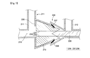
- FIG. 5 is a cross-sectional view illustrating a power generator according to a second exemplary embodiment of the present disclosure.
- FIGS. 6 and 7 are cross-sectional views illustrating an operation of a flow path opening and closing unit in FIG. 5 .
- FIG. 8 is a configuration diagram illustrating an external combustion system according to a third exemplary embodiment of the present disclosure.
- FIG. 9 is a configuration diagram illustrating an internal combustion system according to a fourth exemplary embodiment of the present disclosure.
- FIGS. 10, 12, and 13 are configuration diagrams illustrating an air hybrid power generation system according to a fifth exemplary embodiment of the present disclosure.
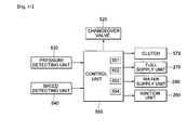
- FIG. 11 is a control block diagram of the air hybrid power generation system according to the fifth exemplary embodiment of the present disclosure.
- constituent elements having the same configuration will be representatively described using the same reference numerals in a first exemplary embodiment, and other exemplary embodiments will be described with regard to only constituent elements that are different from the constituent elements described in the first exemplary embodiment.
- Exemplary embodiments of the present disclosure illustrate ideal exemplary embodiments of the present disclosure in more detail. As a result, various modifications of the drawings are expected. Therefore, the exemplary embodiments are not limited to specific forms in regions illustrated in the drawings, and for example, include modifications of forms by the manufacture.
- an intake device 100 a power generator 200 , an external combustion system 401 using the intake device 100 and the power generator 200 , an internal combustion system 301 using the intake device 100 and the power generator 200 , and an air hybrid power generation system 500 using the intake device 100 and the power generator 200 according to exemplary embodiments of the present disclosure will be described with reference to FIGS. 1 to 13 .
- FIGS. 1 to 4 An intake device 100 according to a first exemplary embodiment of the present disclosure will be described with reference to FIGS. 1 to 4 .
- the intake device 100 includes a circular housing 110 , an annular flow path 115 , an inlet part 111 , a outlet part 112 , a piston 120 , and an opening and closing unit 130 which includes a plurality of opening and closing members 133 and elastic members 139 .
- the housing 110 may be formed in an approximately cylinder shape having a circular cross section.
- a hollow portion 101 may be formed at a center of the housing 110 .
- the flow path 115 may be formed in an annular shape inside the housing 110 . That is, the flow path 115 may be formed in a ring shape based on the center of the housing 110 .
- the inlet part 111 may be installed at one side of the housing 110 .
- the inlet part 111 may guide a fluid to the flow path 115 .
- the inlet part 111 may further include an inlet port formed in the housing 110 , and an inlet tube connected with the inlet port. That is, the fluid flowing into the inlet tube may pass through the inlet port and flow into the flow path 115 of the housing 110 .
- the outlet part 112 may be installed at the other side of the housing 110 .
- the outlet part 112 may guide a discharge of the fluid that has passed through the flow path 115 .
- the outlet part 112 may be installed in the housing 110 so as to be spaced apart from the inlet part 111 installed in the housing 110 .
- the outlet part 112 may further include a discharge port formed in the housing 110 , and a discharge tube connected with the discharge port.
- the fluid which has passed through the flow path 115 , may pass through the discharge port and may be discharged through the discharge tube.
- the piston 120 is disposed in the flow path 115 and may move along the annular flow path 115 .
- a size and a shape of the piston 120 may be variably designed based on a size and a cross-sectional shape of the flow path 115 .
- the piston 120 opens and closes the inlet part 111 and the outlet part 112 by moving in one direction along the flow path 115 , thereby allowing the fluid to flow into the flow path 115 or allowing the fluid, which has passed through the flow path 115 , to be discharged through the outlet part 112 .
- the opening and closing unit 130 is installed between the inlet part 111 and the outlet part 112 and may open and close the flow path 115 .
- the opening and closing unit 130 may be installed in the flow path 115 between the inlet part 111 and the outlet part 112 .
- the opening and closing unit 130 may be installed in an opening and closing unit installation region 113 that protrudes toward both sides of the outside of the housing 110 .
- the opening and closing unit 130 prevents the fluid flowing into the inlet part 111 from being discharged directly to the outlet part 112 without moving along the flow path 115 . That is, the opening and closing unit 130 may selectively divide the flow path 115 .
- the opening and closing unit 130 may include the plurality of opening and closing members 133 and the elastic members 139 .
- the plurality of opening and closing members 133 may include a first opening and closing member 131 and a second opening and closing member 132 . That is, the plurality of opening and closing members 133 may include a pair of opening and closing members.
- the plurality of elastic members 139 may be formed to support the plurality of opening and closing members 133 , respectively.
- the plurality of elastic members 139 may include the first elastic member 137 and the second elastic member 138 .
- the first elastic member 137 is installed between an inner wall of the flow path 115 and the first opening and closing member 131 , and may provide elastic force to the first opening and closing member 131 .
- the second elastic member 138 is installed between the second opening and closing member 132 and an inner wall of the flow path 115 which is opposite to the inner wall of the flow path 115 on which the first elastic member 137 is installed, and the second elastic member 138 may provide elastic force to the second opening and closing member 132 .
- the plurality of opening and closing members 133 opens the flow path 115 by moving away from each other by pressing force of the piston 120 , and closes the flow path 115 by elastic force of the elastic member 139 and pressure of the fluid when the pressing force of the piston 120 is released.
- the fluid between the installation region 113 and an outer circumferential surface of the first opening and closing member 131 and the fluid between the installation region 113 and an outer circumferential surface of the second opening and closing member 132 may provide pressing force to the outer circumferential surfaces of the first opening and closing member 131 and the second opening and closing member 312 in a direction in which the first opening and closing member 131 and the second opening and closing member 132 closes the flow path 115 .
- the flow path 115 may be effectively closed not only by the force of the first elastic member 137 and the second elastic member 138 , but also by the fluid between the installation region 113 and the outer circumferential surface of the first opening and closing member 131 and the fluid between the installation region 113 and the outer circumferential surface of the second opening and closing member 132 .
- one end of the piston 120 protrudes in a rotation direction of the piston 120 so as to have an approximately V shape (wedge shape), and the other end of the first opening and closing member 131 and the other end of the second opening and closing member 132 , which initially come into contact with one end of the piston 120 and are pressed by one end of the piston 120 , have V-shaped grooves, respectively, which may be engaged with one end of the piston 120 , such that the piston 120 and the first and second opening and closing members 131 and 132 are effectively engaged with each other, thereby opening the flow path 115 .
- the piston 120 may open the flow path 115 by effectively rotating in one direction.
- the first opening and closing member 131 and the second opening and closing member 132 may press the first elastic member 137 and the second elastic member 138 by moving away from each other.
- the piston 120 may move while pressing the plurality of opening and closing members 133 so as to open the flow path 115 closed by the plurality of opening and closing members 133 .
- the first opening and closing member 131 and the second opening and closing member 132 may move to be close to each other by elastic force of the first elastic member 137 and the second elastic member 138 , thereby closing the flow path 115 .
- first opening and closing member 131 and the second opening and closing member 132 may effectively close the flow path 115 not only by the elastic force of the first elastic member 137 and the second elastic member 138 , but also by the fluid between the outer circumferential surface of the first opening and closing member 131 and the installation region 113 and the fluid between the outer circumferential surface of the second opening and closing member 132 and the installation region 113 .
- the opening and closing unit 130 may define one region between the opening and closing unit 130 and the piston 120 by dividing the flow path 115 , and the piston 120 may compress the fluid in one region by moving along the flow path 115 , thereby discharging the fluid through the outlet part 112 .
- piston 120 of the intake device 100 may include a first piston 125 and a second piston 127 .
- the first piston 125 precedes the second piston 127 , and the first piston 125 and the second piston 127 may have a phase difference of 180°.
- the intake device 100 may further include a discharge check valve 160 .
- the discharge check valve 160 may be installed in the outlet part 112 of the intake device 100 . Specifically, the discharge check valve 160 may be installed in the discharge tube of the outlet part 112 in order to prevent the discharged fluid passing through the discharge tube from flowing back into the flow path 115 .
- the intake device 100 may further include a rotating shaft 150 , and a housing cover 140 formed with reinforcing ribs 141 .
- the housing cover 140 may be formed in a hollow cylinder shape. In addition, the housing cover 140 may be disposed in the hollow portion 101 formed in the circular housing 110 .
- an outer circumferential surface of the housing cover 140 may be in contact with an inner circumferential surface of the hollow portion 101 formed in the circular housing 110 , and may be rotatably coupled to the housing 110 .
- housing cover 140 and the hollow portion 101 formed in the housing 110 may be coupled so that gastightness is maintained therebetween.
- the outer circumferential surface of the housing cover 140 may be connected with the piston 120 . That is, when the piston 120 moves along the flow path 115 , the housing cover 140 may rotate.
- the rotating shaft 150 may be disposed to penetrate the hollow portion 101 formed in the circular housing 110 . Specifically, the rotating shaft 150 may be installed at a center of the housing cover 140 .
- the housing cover 140 and the rotating shaft 150 may be connected to each other by means of the reinforcing ribs 141 . That is, the plurality of reinforcing ribs 141 , which is radially formed from a center of the rotating shaft 150 , may connect the inner circumferential surface of the housing cover 140 with the rotating shaft 150 .
- the piston 120 may move along the annular flow path 115 by rotational force of the rotating shaft 150 .
- the rotating shaft 150 is rotated to allow the piston 120 to move along the flow path 115 .
- the plurality of opening and closing members 133 may open and close the flow path 115 two times by the first piston 125 and the second piston 127 .
- first piston 125 and the second piston 127 may be connected with the rotating shaft 150 .
- the rotating shaft of the power device and the piston 120 may be connected to the housing cover 140 and the reinforcing ribs 141 so as to allow the piston 120 to move along the flow path 115 .
- the fluid flowing into the intake device 100 according to the first exemplary embodiment of the present disclosure may be gas.
- the gas flowing into one region between the piston 120 and the flow path 115 closed by the opening and closing unit 130 may be compressed between the opening and closing unit 130 and the piston 120 by the movement of the piston 120 in a direction in which the piston 120 moves, and then may be discharged through the outlet part 112 .
- the gas being discharged through the outlet part 112 of the intake device 100 may be gas compressed (pressed) by the piston 120 .
- the fluid may be effectively introduced through the inlet part 111 by negative pressure in the flow path 115 .
- opening and closing unit 130 of the intake device 100 may further include hinge shafts 135 .
- a plurality of hinge shafts 135 may be provided, and may support the plurality of opening and closing members 133 installed in the flow path 115 so that the plurality of opening and closing members 133 is rotatable.
- the opening and closing unit 130 includes the plurality of hinge shafts 135 , and the plurality of hinge shafts 135 may include a first hinge shaft 134 which supports the first opening and closing member 131 , and a second hinge shaft 136 which supports the second opening and closing member 132 .
- one end portion of the first opening and closing member 131 may be rotatably supported by the first hinge shaft 134 , and the other end portion of the first opening and closing member 131 may be supported by the first elastic member 137 .
- the second opening and closing member 132 may also be supported by the second hinge shaft 136 and the second elastic member 138 .
- first hinge shaft 134 and the second hinge shaft 136 may be installed in the flow path 115 so as to be spaced apart from each other.
- the first opening and closing member 131 and the second opening and closing member 132 may move away from each other while rotating about the plurality of hinge shafts 135 , respectively, thereby opening the flow path 115 .
- each of the plurality of opening and closing members 133 may be spaced apart from each other and supported by each of the plurality of hinge shafts 135 , and the other end portion of each of the plurality of opening and closing members 133 may be selectively spaced apart from each other by pressing force of the piston 120 , thereby opening the flow path 115 .
- the plurality of hinge shafts 135 may effectively support the rotations of the plurality of opening and closing members 133 , and may guide the rotations of the plurality of opening and closing members 133 and the movements of the plurality of opening and closing members 133 in a direction in which the plurality of opening and closing members 133 move away from each other, thereby improving a lifespan of the plurality of opening and closing members 133 .
- the plurality of hinge shafts 135 may improve responsiveness of the plurality of opening and closing members 133 that may open and close the flow path 115 .
- a power generator 200 according to a second exemplary embodiment of the present disclosure will be described with reference to FIGS. 5 to 7 .
- the power generator 200 includes a circular power generation housing 210 which has a hollow portion 201 formed at a center thereof, a fluid flow path 215 , a fluid inlet part 211 , a fluid outlet part 212 , a power piston 220 , a shaft 250 , and a flow path opening and closing unit 230 .
- the power generation housing 210 may be formed to have a circular cross section.
- the hollow portion 201 may be formed at the center of the power generation housing 210 .
- a central portion of the power generation housing 210 may be formed in a hollow cylinder shape.
- the fluid flow path 215 may be formed in an annular shape inside the power generation housing 210 .
- the fluid inlet part 211 is installed at one side of the power generation housing 210 , and may guide the inflow of the fluid into the fluid flow path 215 .
- the fluid inlet part 211 may further include a fluid inlet port formed in the power generation housing 210 , and a fluid inlet tube connected with the fluid inlet port. That is, the fluid flowing into the fluid inlet tube may pass through the fluid inlet port and flow into the fluid flow path 215 of the power generation housing 210 .
- the fluid outlet part 212 is installed at the other side of the power generation housing 210 , and may guide a discharge of the fluid which has been introduced from the fluid inlet part 211 and has passed through the fluid flow path 215 .
- the fluid outlet part 212 may be installed in the power generation housing 210 so as to be spaced apart from the fluid inlet part 211 installed in the power generation housing 210 .
- the fluid outlet part 212 may further include a fluid discharge port formed in the power generation housing 210 , and a fluid discharge tube connected with the fluid discharge port.
- the fluid passing through the fluid flow path 215 may be discharged to the outside of the power generation housing 210 through the fluid outlet part 212 .
- the power piston 220 is disposed in the fluid flow path 215 , and may be rotated in one direction along the fluid flow path 212 by the fluid introduced through the fluid inlet part 211 .
- the power piston 220 may be moved by a flow or pressure of the fluid introduced through the fluid inlet part 211 .
- the fluid introduced through the fluid inlet part 211 may rotate the power piston 220 , and may be discharged through the fluid outlet part 212 .
- the shaft 250 is disposed to penetrate the hollow portion 201 formed in the housing 210 and connected with the power piston 220 , such that the shaft 250 may be rotated when the power piston 220 moves along the fluid flow path 215 .
- the power generation housing 210 may further include a housing cover 240 which is rotatably coupled to an inner circumferential surface of the hollow portion 201 of the power generation housing 210 , and reinforcing ribs 241 which connect the shaft 250 and the housing cover 240 .
- the housing cover 240 is formed in a hollow cylinder shape, and may be formed such that the inner circumferential surface of the hollow portion 201 of the power generation housing 210 and an outer circumferential surface of the housing cover 240 are rotatably coupled. In addition, the housing cover 240 may be coupled such that the outer circumferential surface of the housing cover 240 and the inner circumferential surface of the hollow portion 201 of the power generation housing 210 are rotated while maintaining gastightness.
- the shaft 250 is disposed at a center of the housing cover 240 , and may be coupled to the housing cover 240 by means of the reinforcing ribs 241 radially disposed from a central axis of the shaft 250 between the inner circumferential surface of the housing cover 240 and an outer circumferential surface of the shaft 250 .
- the shaft 250 may also rotate.
- the shaft 250 may also make one rotation.
- the power piston 220 of the power generator 200 may include a first power piston 225 and a second power piston 227 .
- the power generator 200 may be formed similar to that illustrated in the perspective view of the aforementioned intake device 100 illustrated in FIG. 1 .
- the flow path opening and closing unit 230 may be installed in the fluid flow path 215 between the fluid inlet part 211 and the fluid outlet part 212 . In addition, the flow path opening and closing unit 230 may selectively divide the fluid flow path 215 .
- the flow path opening and closing unit 230 may be installed in a flow path opening and closing unit installation region 213 that protrudes toward both sides of the outside of the power generation housing 210 .
- the flow path opening and closing unit 230 may include a plurality of flow path opening and closing members 233 , elastic bodies 239 which support the plurality of flow path opening and closing members 233 , respectively, and a catching projection 235 .
- the plurality of flow path opening and closing members 233 may be formed as a pair of a first flow path opening and closing member 231 and a second flow path opening and closing member 232 .
- the elastic bodies 239 may include a first elastic body 237 which is installed between the first flow path opening and closing member 231 and the fluid flow path 215 and provides elastic force to the first flow path opening and closing member 231 , and a second elastic body 238 which is installed between the second flow path opening and closing member 232 and the fluid flow path 215 and provides elastic force to the second flow path opening and closing member 232 .
- the plurality of elastic bodies 239 is formed to provide elastic force to the plurality of flow path opening and closing members 233 , and may support the plurality of flow path opening and closing members 233 , respectively.
- the catching projection 235 is installed in the fluid flow path 215 , and may restrict a movement direction of the plurality of flow path opening and closing members 233 .
- the catching projection 235 is formed in the flow path opening and closing unit installation region 213 so as to protrude toward the fluid flow path 125 in a direction that intersects a sliding direction of the plurality of flow path opening and closing members 233 , thereby restricting the sliding direction of the plurality of flow path opening and closing members 233 .
- the power piston 220 includes the first power piston 225 and the second power piston 227 as illustrated in the aforementioned FIG. 5
- the plurality of flow path opening and closing members 233 may open and close the fluid flow path 215 two times by the first power piston 225 and the second power piston 227 .
- first power piston 225 and the second power piston 227 may be connected with the shaft 250 .
- the plurality of flow path opening and closing members 233 may open the fluid flow path 215 by moving away from each other by pressing force of the power piston 220 .
- the plurality of flow path opening and closing members 233 is moved to be close to each other by elastic force of the elastic bodies 239 , and pressure of the fluid presses the plurality of flow path opening and closing members 233 , thereby closing the fluid flow path 215 .
- the first flow path opening and closing member 231 and the second flow path opening and closing member 232 are pressed by the power piston 220 , the first flow path opening and closing member 231 and the second flow path opening and closing member 232 are moved away from each other, and press the first elastic body 237 and the second elastic body 238 , respectively.
- the power piston 220 moves along the fluid flow path 215 while pressing the first flow path opening and closing member 237 and the second flow path opening and closing member 238 .
- the plurality of flow path opening and closing members 233 slides in the movement direction of the power piston 220 , and the plurality of flow path opening and closing members 233 may open the fluid flow path 215 by moving away from each other.
- first flow path opening and closing member 231 and the second flow path opening and closing member 232 may open the fluid flow path 215 by moving away from each other by pressing force of the power piston 220 and simultaneously moving in the movement direction of the power piston 220 .
- the catching projection 235 is installed inside the fluid flow path 215 so as to be relatively closer to the fluid inlet part 211 than the fluid outlet part 212 , and may inhibit the plurality of flow path opening and closing members 233 from sliding in the movement direction of the power piston 220 .
- the pressing force which presses the first flow path opening and closing member 231 and the second flow path opening and closing member 232 by the power piston 220 , is released, the first flow path opening and closing member 231 and the second flow path opening and closing member 232 are moved to be close to each other by restoring force of the first elastic body 237 and the second elastic body 238 , and close the fluid flow path 215 by pressing force of the fluid which presses surfaces of the plurality of flow path opening and closing members 233 that face the catching projection 235 in a direction in which the fluid flow path 215 is closed, thereby dividing the fluid flow path 215 .
- the fluid between the catching projection 235 and the plurality of flow path opening and closing members 233 may be pressed in a direction in which the plurality of flow path opening and closing members 233 closes the fluid flow path 215 . Therefore, the fluid flow path 215 may be effectively closed not only by elastic force of the elastic body 239 , but also by the fluid between the catching projection 235 and the plurality of flow path opening and closing members 233 .
- the flow path opening and closing unit 230 may define one region between the fluid inlet part 211 and the power piston 220 by dividing the fluid flow path 215 , and as a result, the power piston 220 may discharge the fluid, which has been introduced through the fluid inlet part 211 and has rotated the power piston 220 , through the fluid outlet part 212 by moving along the fluid flow path 215 by the flow and pressure of the fluid flowing into one region.
- the power piston 220 rotates along the annular fluid flow path 215 , and as a result, the fluid may effectively flow into the fluid flow path 215 through the fluid inlet part 211 by positive pressure of the fluid.
- the power piston 220 which moves along the annular fluid flow path 215 , is moved by pressure of the introduced fluid, and rotates the shaft 250 connected with the power piston 220 , thereby effectively transmitting rotational power.
- An external combustion system 401 according to a third exemplary embodiment of the present disclosure will be described with reference to FIG. 8 .
- descriptions of constituent elements identical to the constituent elements of the first exemplary embodiment and the second exemplary embodiment of the present disclosure will be omitted.
- An external combustion system 401 includes a circulation line 410 , a boiler 420 , the power generator 200 , a cooler 430 , and the intake device 100 .
- the fluid is stored in the circulation line 410 .
- the circulation line 410 is formed in the form of a closed loop, and may circulate the fluid stored therein.
- the fluid stored in the circulation line 410 may be water that is vaporized by being heated.
- the boiler 420 heats the circulation line 410 and vaporizes the fluid stored in the circulation line 410 .
- the boiler 420 may further include an air supply unit 421 which is formed to be opened at one side of a boiler housing having a combustion chamber therein, and an exhaust unit 422 which is formed at the other side of the boiler housing and discharges the air which has been introduced through the air supply unit 421 and has been combusted in the combustion chamber.
- a non-illustrated fuel supply device may be installed in the combustion chamber of the boiler 420 .
- a temperature of the fluid stored in the circulation line 410 passing through the combustion chamber is increased by heat generated in the combustion chamber of the boiler 420 , and as a result, the fluid may be vaporized.
- the vaporized fluid in the circulation line 410 may be supplied to the power generator 200 . That is, the fluid vaporized by the boiler 420 may flow into the power generator 200 .
- the power generator 200 may have the same configuration as the power generator 200 of the second exemplary embodiment.
- the fluid which is stored in the circulation line 410 and vaporized by the boiler 420 , may be supplied through the fluid inlet part 211 .
- the vaporized fluid may be supplied through the fluid inlet part 211 so as to move the power piston 220 , and may be discharged through the fluid outlet part 212 .
- the fluid discharged through the fluid outlet part 212 of the power generator 200 may cool the fluid vaporized by the cooler 430 and change a phase of the fluid.
- the fluid (steam) vaporized by the boiler 420 may become water again by being cooled by the cooler 430 .
- the cooler 430 may cool the fluid stored in the circulation line 410 .
- the circulation line 410 may be cooled in an air-cooled manner.
- circulation line 410 is installed between the cooler 430 and the boiler 420 , and may circulate the fluid stored therein.
- the intake device 100 may allow the fluid in the circulation line 410 to be supplied to the boiler 420 so that the fluid cooled by the cooler 430 is heated by the boiler 420 .
- the intake device 100 may be installed between the cooler 430 and the boiler 420 .
- the intake device 100 may include the same configuration as the intake device 100 of the first exemplary embodiment of the present disclosure.
- the intake device 100 according to the third exemplary embodiment of the present disclosure may be a pump.
- the fluid cooled by the cooler 430 may be supplied to the intake device 100 through the inlet part 111 .
- the piston 120 of the intake device 100 is connected with the shaft 250 of the power generator 200 , such that the piston 120 may be rotated together with the shaft 250 when the shaft 250 rotates. Therefore, the fluid flowing into the intake device 100 through the inlet part 111 may be discharged through the outlet part 112 by the rotation of the piston 120 , and may be supplied to the circulation line 410 .
- a part of the circulation line 410 connects the outlet part 112 of the intake device 100 and the fluid inlet part 211 of the power generator 200 , and the fluid stored in the circulation line 410 is heated by the boiler 420 .
- the remaining part of the circulation line 410 connects the fluid outlet part 212 of the power generator 200 and the inlet part 111 of the intake device 100 , and the vaporized fluid in the circulation line 410 may be cooled by the cooler 130 .
- the rotating shaft 150 and the shaft 250 of the power generator 200 may be connected to each other and rotated together.
- piston 120 of the intake device 100 may be directly connected to the shaft 250 of the power generator 200 .
- one side of the shaft 250 of the power generator 200 may transmit power to a non-illustrated device, and the other side of the shaft 250 of the power generator 200 may rotate the piston 120 of the intake device 100 .
- the external combustion system 401 may transmit power by the rotation of the shaft 250 of the power generator 200 and effectively rotate the piston 120 of the intake device 100 .
- the shaft 250 of the power generator 200 may effectively rotate the piston 120 of the intake device 100 without using a separate power source for allowing the fluid stored in the circulation line 410 to flow.
- An internal combustion system 301 according to a fourth exemplary embodiment of the present disclosure will be described with reference to FIG. 9 .
- descriptions of constituent elements identical to the constituent elements of the first exemplary embodiment and the second exemplary embodiment of the present disclosure will be omitted.
- An internal combustion system 301 includes the intake device 100 , the power generator 200 , a fuel supply unit 270 , an ignition unit 260 , and a water supply unit 280 .
- the intake device 100 may include the same configuration as the intake device 100 of the first exemplary embodiment of the present disclosure.
- the power generator 200 may include the same configuration as the power generator 200 of the second exemplary embodiment of the present disclosure.
- the fuel supply unit 270 may supply fuel into the fluid flow path 215 of the power generator 200 .
- the fuel supply unit 270 is installed at one side of the power generation housing 210 of the power generator 200 , and may supply fuel into the fluid flow path 215 .
- the pressed gas discharged through the outlet part 112 of the intake device 100 flows into the fluid flow path 215 through the fluid inlet part 211 of the power generator 200 .
- the gas and the fuel may be mixed in the fluid flow path 215 .
- the ignition unit 260 may ignite the gas mixed with the fuel in the fluid flow path 215 .
- the ignition unit 260 may be installed in the power generation housing 210 of the power generator 200 so as to be adjacent to the fuel supply unit 270 .
- the ignition unit 260 ignites the gaseous mixture formed by mixing the gas and the fuel in the fluid flow path 215 such that the gaseous mixture explodes in the fluid flow path 215 .
- the power piston 220 moves along the fluid flow path 215 by explosive power, and the shaft 250 connected with the power piston 220 rotates, thereby transmitting power. That is, the shaft 250 connected to the power piston 220 , which moves along the fluid flow path 215 , may generate rotational power by rotating.
- the water supply unit 280 may supply water into the fluid flow path 215 .
- the water supply unit 280 may be installed in the power generation housing 210 of the power generator 200 .
- the water supply unit 280 may supply water into the fluid flow path 215 after the power piston 220 rotates along the fluid flow path 215 to make one rotation by explosive power generated as a mixed fluid, which is made by mixing the fuel supplied by the fuel supply unit 270 and the fluid in the fluid flow path 215 , is ignited by the ignition unit 260 and combusted.
- the water supply unit 280 supplies water into the fluid flow path 215 after the interior of the fluid flow path 215 is heated by the combustion in the interior of the fluid flow path 215 , such that the water and the compressed gas introduced through the fluid inlet part 215 may be mixed and the water may be vaporized by the heated fluid flow path 215 . Therefore, pressure of the water vaporized in the fluid flow path 215 is increased, and may rotate the power piston 220 . That is, the power piston 220 may rotate along the fluid flow path 215 to make one rotation by the vaporization of water supplied from the water supply unit 280 .
- the fuel supply unit 270 and the ignition unit 260 may operate alternately with the water supply unit 280 by a non-illustrated control unit.
- the water supply unit 280 may cool the interior of the fluid flow path 215 which has been heated by the combustion.
- the rotational power of the shaft 250 is connected with the piston 120 inside the intake device 100 , such that the fluid may smoothly flow into the intake device 100 .
- the shaft 250 and the piston 120 inside the intake device 100 may be connected in the same manner as that in the aforementioned third exemplary embodiment.
- the water supply unit 280 may supply water into the fluid flow path 215 after the first power piston 225 or the second power piston 227 of the power piston 220 rotates along the fluid flow path 215 by explosive power generated as a mixed fluid, which is made by mixing the fuel supplied by the fuel supply unit 270 and the fluid in the fluid flow path 215 , is ignited by the ignition unit 260 and combusted.
- the water supply unit 280 supplies water into the fluid flow path 215 after the interior of the fluid flow path 215 is heated by the combustion in the interior of the fluid flow path 215 , such that the water and the compressed gas introduced through the fluid inlet part 215 may be mixed and the water may be vaporized by the heated fluid flow path 215 . Therefore, pressure of the water vaporized in the fluid flow path 215 is increased, and may rotate the power piston 220 .
- first power piston 225 or the second power piston 227 of the power piston 220 may rotate along the fluid flow path 215 by the vaporization of the water supplied from the water supply unit 280 .
- the first power piston 225 and the second power piston 227 rotate along the fluid flow path 215 to make one rotation while the shaft 250 rotates to make one rotation, thereby effectively generating power. That is, the first power piston 225 or the second power piston 227 opens and closes the plurality of flow path opening and closing members 233 , and opens and closes the plurality of flow path opening and closing members 233 two times while the shaft 250 rotates to make one rotation.
- the power generator 200 of the internal combustion system 301 may further include an inlet check valve 290 .
- the inlet check valve 290 may be installed in the fluid inlet part 211 of the power generator 200 . Specifically, the inlet check valve 290 is installed in the fluid inlet tube of the fluid inlet part 211 in order to prevent the fluid passing through the fluid inlet tube from being discharged through the fluid inlet part 211 .
- the inlet check valve 290 may be opened when the fluid flows into the fluid flow path 215 of the power generator 200 through the fluid inlet part 211 , and the inlet check valve 290 may be closed when there is no fluid to be introduced through the fluid inlet part 211 .
- the internal combustion system 301 not only generates power by combusting fuel like a typical internal combustion engine, but also generates power by rotating the power piston 220 by the vaporization of the water supplied from the water supply unit 280 .
- the internal combustion system 301 may reduce fuel consumption in comparison with an internal combustion engine in the related art, and effectively reduce nitrogen oxide included in exhaust gas generated by the combustion of fuel.
- An air hybrid power generation system 500 according to a fifth exemplary embodiment of the present disclosure will be described with reference to FIGS. 10 to 13 .
- descriptions of constituent elements identical to the constituent elements of the first exemplary embodiment and the second exemplary embodiment of the present disclosure will be omitted.
- An air hybrid power generation system 500 includes an air tank 510 , the intake device 100 , the power generator 200 , the fuel supply unit 270 , the ignition unit 260 , and a changeover valve 520 .
- the air tank 510 stores compressed air therein. Specifically, the interior of the air tank 510 may be filled with compressed air.
- the intake device 100 may include the same configuration as the intake device 100 of the first exemplary embodiment of the present disclosure. Therefore, the intake device 100 may introduce outside air through the inlet part 111 .
- the power generator 200 may include the same configuration as the power generator 200 of the second exemplary embodiment of the present disclosure. Specifically, the air supplied to the power generator 200 may be supplied from the air tank 510 , or may be supplied through the outlet part 112 of the intake device 100 .
- the fuel supply unit 270 and the ignition unit 260 may be formed to have the same configurations as the fuel supply unit 270 and the ignition unit 260 included in the internal combustion system 301 of the aforementioned fourth exemplary embodiment of the present disclosure.
- the fluid is supplied into the fluid flow path 215 through the fluid inlet part 211 of the power generator 200 , and the power piston 220 is rotated by explosive pressure generated as a mixed fluid, which is made by mixing the fluid and the fuel supplied by the fuel supply unit 270 , is ignited by the ignition unit 260 and combusted, thereby generating rotational power of the shaft 250 .
- the changeover valve 520 may allow the compressed air stored in the air tank 510 or the outside air discharged through the outlet part 112 of the intake device 100 to be selectively supplied to the power generator 200 .
- the compressed air stored in the air tank 510 may be supplied to the power generator 200 or the outside air discharged through the outlet part 112 of the intake device 100 may be supplied to the power generator 200 .
- a drive apparatus having the hybrid power generation system 500 such as an automobile may supply air to the power generator 200 selectively by the air tank 510 or the intake device 100 .
- the air hybrid power generation system 500 of the fifth exemplary embodiment of the present disclosure may further include a control unit 550 .
- the control unit 550 may control the operation of the changeover valve 520 . That is, the control unit 550 operates the changeover valve 520 so as to allow the compressed air stored in the air tank 510 to be supplied to the power generator 200 or allow the outside air discharged through the outlet part 112 of the intake device 100 to be supplied to the power generator 200 .
- the air hybrid power generation system 500 may further include a speed detecting unit 540 . Therefore, the control unit 550 detects a speed of the drive apparatus having the air hybrid power generation system 500 , and may control the operation of the changeover valve 520 by determining and comparing information of the speed detected by the speed detecting unit 540 and a predetermined speed preset to the control unit 550 .
- the speed detecting unit 540 may determine whether the automobile accelerates or decelerates by detecting a separate speed detecting sensor or a rotation angle of an accelerator of the automobile.
- the intake device 100 of the air hybrid power generation system 500 may further include the discharge check valve 160 .
- the discharge check valve 160 may be installed in the outlet part 112 of the intake device 100 . Specifically, the discharge check valve 160 may be installed in the discharge tube of the outlet part 112 in order to prevent the discharged fluid passing through the discharge tube from flowing back into the flow path 115 .
- the discharge check valve 160 may be opened when the fluid is discharged to the outside of the flow path 115 of the intake device 100 through the outlet part 112 , and the discharge check valve 160 may be closed when there is no fluid to be discharged through the outlet part 112 .
- control unit 550 may include a first mode 551 , a second mode 552 , and a third mode 553 .
- the control unit 550 may control the changeover valve 520 to allow the fluid discharged from the intake device 100 to be supplied to the air tank 510 . That is, in the first mode 551 , the outlet part 112 of the intake device 100 and an entrance portion 511 of the air tank 510 may communicate with each other. In this case, no air is supplied to the power generator 200 .
- the outside air introduced through the inlet part 111 of the intake device 100 may flow into the entrance portion 511 of the air tank 510 through the outlet part 112 of the intake device 100 by using rotational force of the rotating shaft 150 of the intake device 100 , thereby filling the air tank 510 with air.
- the outside air introduced through the inlet part 111 of the intake device 100 may be supplied to the air tank 510 through the outlet part 112 of the intake device 100 , and the outside air supplied to the air tank 510 by the rotation of the piston 120 of the intake device 100 may be compressed, and thus the air tank 510 is filled with the air.
- the air hybrid power generation system 500 may include a valve 295 .
- the valve 295 may be installed at one side of the fluid inlet part 211 of the power generator 200 .
- the valve 295 is opened, such that the outside air may be supplied into the fluid flow path 215 , moved along the fluid flow path 215 by the power piston 220 , and then discharged through the fluid outlet part 212 .
- the control unit 550 may control the changeover valve 520 to supply the compressed air stored in the air tank 510 to the power generator 200 .
- the changeover valve 520 may allow the power generator 200 and the air tank 510 to communicate with each other, and may close the outlet part 112 of the intake device 100 .
- the changeover valve 520 allows only the compressed air stored in the air tank 510 to be supplied to the power generator 200 .
- power may be produced by rotational force of the shaft 250 of the power generator 200 which is rotated only by the compressed air of the air tank 510 .
- control unit 550 may stop the operations of the fuel supply unit 270 and the ignition unit 260 which supply fuel to the power generator 200 , such that the combustion is not performed by the compressed air in the power generator 200 .
- the drive apparatus having the air hybrid power generation system 500 may be operated only by the compressed air stored in the air tank 310 .
- the drive apparatus may effectively reduce nitrogen oxide and the like included in exhaust gas generated when the air and the fuel are combusted, and may effectively reduce fuel consumption.
- the hybrid power generation system 500 may further include the rotating shaft 150 and a clutch 570 .
- the rotating shaft 150 may be formed in the same shape as the intake device 100 of the first exemplary embodiment of the present disclosure.
- the clutch 570 may include a first clutch portion 571 which is installed at one end portion of the rotating shaft 150 of the intake device 100 , and a second clutch portion 572 which is engaged with the first clutch portion 571 and may rotate together with the rotating shaft 150 . That is, the clutch 570 may be installed between one end portion of the rotating shaft 150 of the intake device 100 and the shaft 250 of the power generator 200 which faces one end portion of the rotating shaft 150 of the intake device 100 .
- the second clutch portion 572 is installed at one end portion of the shaft 250 of the power generator 200 which faces one end portion of the rotating shaft 150 , and may be selectively engaged with the first clutch portion 571 .
- the clutch 570 may be controlled by the control unit 550 .
- the first clutch portion 571 and the second clutch portion 572 are spaced apart from each other, such that power may be generated only by the rotation of the shaft 250 of the power generator 200 .
- the control unit 550 controls the changeover valve 520 , such that the compressed air stored in the air tank 510 and the outside air passing through the outlet part 112 of the intake device 100 may be supplied to the power generator 200 .
- the changeover valve 520 allows the compressed air passing through the entrance portion 511 of the air tank 510 and the outside air passing through the outlet part 112 of the intake device 100 to communicate with the power generator 200 .
- control unit 550 may operate the fuel supply unit 270 and the ignition unit 260 to inject the fuel into the fluid flow path 215 of the power generator 200 , and may allow a mixed fluid, which is made by mixing the fuel and the fluid in the fluid flow path 215 , to be ignited and combusted.
- control unit 550 may control the changeover valve 520 , the fuel supply unit 270 , and the ignition unit 260 in the third mode 553 , thereby improving the rotation of the shaft 250 of the power generator 200 .
- the fluid flowing into the fluid inlet part 211 of the power generator 200 , the outside air passing through the outlet part 111 of the intake device 100 , and the compressed air stored in the air tank 510 may flow into the power generator 200 and combusted.
- the air hybrid power generation system 500 may further include a pressure detecting unit 530 .
- the pressure detecting unit 530 may detect pressure in the air tank 510 . That is, the pressure detecting unit 530 may detect the amount of compressed air stored in the air tank 510 .
- control unit 550 may further include a fourth mode 554 .
- control unit 550 When the control unit 550 controls the changeover valve 520 so that the compressed air stored in the air tank 510 is supplied to the power generator 200 and the outlet part 111 of the intake device 100 is closed, the control unit 550 may combust the compressed air supplied to the power generator 200 by comparing information detected by the pressure detecting sensor 530 and a present pressure value.
- control unit 550 may determine that the shaft 250 of the power generator 200 cannot be effectively rotated by the compressed air stored in the air tank 510 , and may operate the fuel supply unit 270 and the ignition unit 260 such that the combustion is performed in the fluid flow path 215 of the power generator 200 .
- the first clutch portion 571 and the second clutch portion 572 are spaced apart from each other, and as a result, power may be generated only by the rotation of the shaft 250 . That is, in the second mode 552 and the fourth mode 554 , the control unit 550 may allow the rotating shaft 150 of the intake device 100 and the shaft 250 of the power generator 200 to be spaced apart from each other.
- control unit 550 may control the clutch 570 so that the rotating shaft 150 of the intake device 100 and the shaft 250 of the power generator 200 are engaged with each other.
- the control unit 550 controls the changeover valve 520 so that the compressed air stored in the air tank 510 is supplied to the power generator 200 and the outlet part 111 of the intake device 100 is closed, and in a case in which the information detected by the pressure detecting sensor 530 is below the preset pressure value, the control unit 550 controls the clutch 570 and the changeover valve 520 so as to allow air to be supplied to the power generator 200 through the intake device 100 .
- control unit 550 may control the clutch 570 so that the rotating shaft 150 and the shaft 250 are engaged with each other, and may control the changeover valve 520 so that air is supplied to the power generator 200 through the intake device 100 .
- control unit 550 of the air hybrid power generation system 500 may operate in various modes based on a preset value according to a speed or based on pressure of the compressed air stored in the air tank 510 .
- the combustion is selectively performed in the power generator 200 in accordance with a state of the drive apparatus having the air hybrid power generation system 500 , and as a result, it is possible to fill the air tank 510 with air when the drive apparatus decelerates, and generate power only by the compressed air in the air tank 510 when the drive apparatus travels at a low speed, thereby preventing exhaust gas including nitrogen oxide from being discharged.
- the air hybrid power generation system 500 may further include the water supply unit 280 .
- the water supply unit 280 may be formed to have the same configuration as the water supply unit 280 of the aforementioned fourth exemplary embodiment of the present disclosure.
- the water supply unit 280 may be controlled by the control unit 550 . Specifically, the water supply unit 280 injects water into the fluid flow path 215 heated after the fuel supply unit 270 and the ignition unit 260 are operated by the control unit 550 and the combustion is performed in the power generator 200 , and the power piston 220 may be rotated by pressure of the vaporized fluid.
- the water supply unit 280 may be controlled by the control unit 550 alternately with the fuel supply unit 270 and the ignition unit 260 . Specifically, while the power piston 220 rotates along the fluid flow path 215 to make one rotation, the fuel supply unit 270 and the ignition unit 260 may be operated and the water supply unit 280 may be stopped, and thereafter, while the power piston 220 rotates along the fluid flow path 215 to make one rotation, the fuel supply unit 270 and the ignition unit 260 may be stopped and the water supply unit 280 may be operated.
- control unit 550 may operate the water supply unit 280 .
- the air hybrid power generation system 500 may rotate the power piston 220 by vapor evaporated not only by the combustion of fuel but also by using the water supply unit 280 , and as a result, it is possible to reduce fuel consumption and reduce the amount of nitrogen oxide included in exhaust gas.
Landscapes
- Engineering & Computer Science (AREA)
- Mechanical Engineering (AREA)
- General Engineering & Computer Science (AREA)
- Chemical & Material Sciences (AREA)
- Combustion & Propulsion (AREA)
- Physics & Mathematics (AREA)
- Fluid Mechanics (AREA)
- Geometry (AREA)
- Other Liquid Machine Or Engine Such As Wave Power Use (AREA)
- Hydraulic Motors (AREA)
- Connection Of Motors, Electrical Generators, Mechanical Devices, And The Like (AREA)
Abstract
An exemplary embodiment of the present disclosure provides an intake device including: an annular flow path which is formed in a circular housing; an inlet part which is installed at one side of the housing and guides an inflow of a fluid into the flow path; a outlet part which is installed at the other side of the housing and guides a discharge of the fluid which flows into the inlet part and passes through the flow path; a piston which is disposed in the flow path, and rotates along the flow path so as to compress the fluid introduced through the inlet part; and an opening and closing unit which is installed in the flow path between the inlet part and the outlet part, includes a plurality of opening and closing members, and elastic members which are installed between the plurality of opening and closing members and the flow path so as to support the plurality of opening and closing members, respectively, and opens and closes the flow path by pressing the piston, in which when the pressing of the piston is released, the plurality of opening and closing members closes the flow path by pressing force of the fluid which presses outer circumferential surfaces of the plurality of opening and closing members in a direction in which the flow path is closed, and by elastic force of the elastic member.
Description
- An exemplary embodiment of the present disclosure relates to an intake device, a power generator, and a power system using the intake device and the power generator, and more particularly, to an intake device and a power generator, which each include a piston that moves along an annular flow path inside a circular housing, and a power system using the intake device and the power generator.
- In general, an intake device is coupled to a separate motor or the like, and introduces or presses a fluid. The intake device is required to have valves which are opened and closed to introduce and discharge the fluid into and from the intake device, and a crank shaft.
- However, there are problems in that a structure of the intake device is complicated because the structure includes a valve for opening and closing an inflow of the fluid and a valve for opening and closing a discharge of the fluid, and efficiency deteriorates due to a mechanical loss because a rotational motion is converted into a rectilinear reciprocating motion of a piston through the crank shaft.
- In general, the power generator has a complicated structure such as a crank shaft, an intake valve and an exhaust valve which each open and close an intake port and an exhaust port.
- Therefore, there is a problem in that efficiency deteriorates due to a mechanical loss because the rectilinear reciprocating motion of the piston is transmitted as a rotational motion through the crank shaft.
- In addition, a power system using the intake device and the power generator has a problem in that efficiency deteriorates because of the intake device and the power generator having the complicated structures.
- Exemplary embodiments of the present disclosure may provide an intake device which has a simple structure and introduces a fluid through a rotational motion, a power generator which may effectively produce power by the rotation of a piston that moves along an annular flow path, and a power system using the intake device and the power generator.
- An exemplary embodiment of the present disclosure provides an intake device including: an annular flow path which is formed in a circular housing; an inlet part which is installed at one side of the housing and guides an inflow of a fluid into the flow path; a outlet part which is installed at the other side of the housing and guides a discharge of the fluid which flows into the inlet part and passes through the flow path; a piston which is disposed in the flow path, and rotates along the flow path so as to compress the fluid introduced through the inlet part; and an opening and closing unit which is installed in the flow path between the inlet part and the outlet part, includes a plurality of opening and closing members, and elastic members which are installed between the plurality of opening and closing members and the flow path so as to support the plurality of opening and closing members, respectively, and opens and closes the flow path by pressing the piston, in which when the pressing of the piston is released, the plurality of opening and closing members closes the flow path by pressing force of the fluid which presses outer circumferential surfaces of the plurality of opening and closing members in a direction in which the flow path is closed, and by elastic force of the elastic member.
- In addition, the opening and closing unit may further include hinge shafts that allow the plurality of opening and closing members to be rotated based on one side thereof so as to be away from each other when the plurality of opening and closing members opens the flow path.
- In addition, the piston may include: a first piston which moves along the flow path; and a second piston which moves along the flow path while having a phase difference of 180 degrees with the first piston.
- Another exemplary embodiment of the present disclosure provides a power generator including: a circular power generation housing which has a hollow portion formed at a center thereof; an annular fluid flow path which is formed in the power generation housing; a fluid inlet part which is installed at one side of the power generation housing and guides an inflow of a fluid into the fluid flow path; a fluid outlet part which is installed at the other side of the power generation housing and guides a discharge of the fluid which flows into the fluid inlet part and passes through the fluid flow path; a power piston which is disposed in the fluid flow path, and rotates along the fluid flow path by the fluid introduced through the fluid inlet part; a shaft which penetrates the hollow portion of the power generation housing, and is connected with the power piston so as to rotate together with the power piston when the power piston rotates; and a flow path opening and closing unit which is installed in the fluid flow path between the fluid inlet part and the fluid outlet part, and includes a plurality of flow path opening and closing members, elastic bodies that are installed between the plurality of flow path opening and closing members and the fluid flow path and support the plurality of flow path opening and closing members, respectively, and a catching projection that inhibits the plurality of flow path opening and closing members from sliding in the movement direction of the power piston, in which the plurality of flow path opening and closing members opens the fluid flow path by moving away from each other while sliding in the movement direction of the power piston by pressing force of the power piston, and when pressing force of the power piston is released, the plurality of flow path opening and closing members closes the fluid flow path by pressing force of the fluid between the plurality of flow path opening and closing members and the catching projection in a direction in which the fluid flow path is closed, and by elastic force of the elastic bodies.
- In addition, the power piston may include: a first power piston which moves along the fluid flow path; and a second power piston which moves along the fluid flow path while having a phase difference of 180 degrees with the first power piston.
- Yet another exemplary embodiment of the present disclosure provides an external combustion system including: a circulation line in which a fluid is stored; a boiler which heats the circulation line, and vaporizes the fluid stored in the circulation line; a power generator according to claim 4 into which the fluid vaporized by the boiler flows; a cooler which cools the circulation line in which the fluid discharged after passing through the power generator is stored; and an intake device according to any one of claims 1 to 3 which supplies the fluid in the circulation line cooled by the cooler to the boiler.
- Still another exemplary embodiment of the present disclosure provides an internal combustion system including: a power generator according to claim 4; a fuel supply unit which supplies fuel to a fluid flow path of the power generator; an ignition unit which ignites a fluid which is mixed with the fuel supplied by the fuel supply unit and passes through the fluid flow path of the power generator; and a water supply unit which supplies water to the fluid flow path of the power generator, in which the water supply unit supplies water into the fluid flow path of the power generator when the interior of the fluid flow path of the power generator is heated, such that a power piston of the power generator is rotated by evaporated vapor.
- Still yet another exemplary embodiment of the present disclosure provides an air hybrid power generation system including: an air tank in which compressed air is stored; an intake device according to any one of claims 1 to 3 which introduces outside air; a power generator according to claim 4 into which a fluid passing through the intake device flows; a fuel supply unit which supplies fuel to a fluid flow path of the power generator; an ignition unit which ignites a fluid which is mixed with the fuel supplied by the fuel supply unit and passes through the fluid flow path of the power generator; and a changeover valve which is installed between the air tank, the intake device, and the power generator, and changes an inflow and an outflow of the fluid to the air tank, the intake device, and the power generator.
- In addition, the air hybrid power generation system may further include a control unit which controls the changeover valve, in which the control unit includes a first mode which controls the changeover valve so that the fluid discharged from the intake device is supplied to the air tank, a second mode which controls the changeover valve so that compressed air in the air tank is supplied to the power generator, and a third mode which controls the changeover valve so that the compressed air in the air tank and the fluid discharged from the intake device are supplied to the power generator.
- In addition, the air hybrid power generation system may further include: a pressure detecting unit which detects internal pressure of the air tank, in which the control unit further includes a fourth mode which controls the changeover valve so that the compressed air in the air tank is supplied to the power generator, and combusts a fluid supplied to the power generator in accordance with information detected by the pressure detecting unit.
- In addition, the air hybrid power generation system may further include: a rotating shaft which is connected with a piston of the intake device; and a clutch which is installed between one end portion of the rotating shaft and one end portion of the shaft which faces one end portion of the rotating shaft, and allows the rotating shaft and the shaft to be engaged with each other, in which the clutch is controlled by the control unit, and allows the rotating shaft and the shaft to be spaced apart from each other in the second mode and the fourth mode.
- In addition, the air hybrid power generation system may further include: a water supply unit which supplies water to the fluid flow path of the power generator, in which the control unit alternately controls the water supply unit and the ignition unit to supply water into the fluid flow path of the power generator when the interior of the fluid flow path of the power generator is heated, such that a power piston of the power generator is rotated by using evaporated vapor.
- According to the exemplary embodiments of the present disclosure, the intake device or the power generator may introduce a fluid by using a simplified structure or may generate power by the introduced fluid, and the power system using the intake device and the power generator may produce and consume power with improved efficiency.
-
FIG. 1 is a perspective view illustrating an intake device according to a first exemplary embodiment of the present disclosure. -
FIG. 2 is a cross-sectional view illustrating a cross section ofFIG. 1 . -
FIGS. 3 and 4 are cross-sectional views illustrating an operation of an opening and closing unit inFIG. 1 . -
FIG. 5 is a cross-sectional view illustrating a power generator according to a second exemplary embodiment of the present disclosure. -
FIGS. 6 and 7 are cross-sectional views illustrating an operation of a flow path opening and closing unit inFIG. 5 . -
FIG. 8 is a configuration diagram illustrating an external combustion system according to a third exemplary embodiment of the present disclosure. -
FIG. 9 is a configuration diagram illustrating an internal combustion system according to a fourth exemplary embodiment of the present disclosure. -
FIGS. 10, 12, and 13 are configuration diagrams illustrating an air hybrid power generation system according to a fifth exemplary embodiment of the present disclosure. -
FIG. 11 is a control block diagram of the air hybrid power generation system according to the fifth exemplary embodiment of the present disclosure. -
-
- 100: Intake device
- 110: Housing
- 111: Inlet part
- 112: Outlet part
- 115: Flow path
- 120: Piston
- 130: Opening and closing unit
- 133: Plurality of opening and closing members
- 135: Hinge shaft
- 139: Elastic member
- 150: Rotating shaft
- 200: Power generator
- 201: Hollow portion
- 210: Power generation housing
- 211: Fluid inlet part
- 212: Fluid outlet part
- 215: Fluid flow path
- 220: Power piston
- 230: Flow path opening and closing unit
- 233: Plurality of flow path opening and closing members
- 239: Elastic body
- 235: Catching projection
- 260: Ignition unit
- 270: Fuel supply unit
- 280: Water supply unit
- 301: Internal combustion system
- 401: External combustion system
- 410: Circulation line
- 420: Boiler
- 430: Cooler
- 500: Air hybrid power generation system
- 510: Air tank
- 520: Changeover valve
- 530: Pressure detecting unit
- 550: Control unit
- 551: First mode
- 552: Second mode
- 553: Third mode
- 554: Fourth mode
- 570: Clutch
- Hereinafter, exemplary embodiments of the present disclosure will be described in detail with reference to the accompanying drawings so that those skilled in the technical field to which the present disclosure pertains may easily carry out the exemplary embodiments. The present disclosure may be implemented in various different ways, and is not limited to the exemplary embodiments described herein.
- In several exemplary embodiments, constituent elements having the same configuration will be representatively described using the same reference numerals in a first exemplary embodiment, and other exemplary embodiments will be described with regard to only constituent elements that are different from the constituent elements described in the first exemplary embodiment.
- It is noted that the drawings are schematic, and are not illustrated based on actual scales. Relative dimensions and proportions of parts illustrated in the drawings are exaggerated or reduced in size for the purpose of clarity and convenience in the drawings, and any dimension is just illustrative but not restrictive. Further, the same reference numerals designate the same structures, elements or components illustrated in two or more drawings in order to exhibit similar characteristics.
- Exemplary embodiments of the present disclosure illustrate ideal exemplary embodiments of the present disclosure in more detail. As a result, various modifications of the drawings are expected. Therefore, the exemplary embodiments are not limited to specific forms in regions illustrated in the drawings, and for example, include modifications of forms by the manufacture.
- Hereinafter, an
intake device 100, apower generator 200, anexternal combustion system 401 using theintake device 100 and thepower generator 200, aninternal combustion system 301 using theintake device 100 and thepower generator 200, and an air hybridpower generation system 500 using theintake device 100 and thepower generator 200 according to exemplary embodiments of the present disclosure will be described with reference toFIGS. 1 to 13 . - An
intake device 100 according to a first exemplary embodiment of the present disclosure will be described with reference toFIGS. 1 to 4 . - As illustrated in
FIGS. 1 and 2 , theintake device 100 includes acircular housing 110, anannular flow path 115, aninlet part 111, aoutlet part 112, apiston 120, and an opening andclosing unit 130 which includes a plurality of opening and closingmembers 133 and elastic members 139. - Specifically, the
housing 110 may be formed in an approximately cylinder shape having a circular cross section. In addition, ahollow portion 101 may be formed at a center of thehousing 110. - The
flow path 115 may be formed in an annular shape inside thehousing 110. That is, theflow path 115 may be formed in a ring shape based on the center of thehousing 110. - The
inlet part 111 may be installed at one side of thehousing 110. In addition, theinlet part 111 may guide a fluid to theflow path 115. - Specifically, the
inlet part 111 may further include an inlet port formed in thehousing 110, and an inlet tube connected with the inlet port. That is, the fluid flowing into the inlet tube may pass through the inlet port and flow into theflow path 115 of thehousing 110. - The
outlet part 112 may be installed at the other side of thehousing 110. In addition, theoutlet part 112 may guide a discharge of the fluid that has passed through theflow path 115. - Specifically, the
outlet part 112 may be installed in thehousing 110 so as to be spaced apart from theinlet part 111 installed in thehousing 110. In addition, theoutlet part 112 may further include a discharge port formed in thehousing 110, and a discharge tube connected with the discharge port. - That is, the fluid, which has passed through the
flow path 115, may pass through the discharge port and may be discharged through the discharge tube. - The
piston 120 is disposed in theflow path 115 and may move along theannular flow path 115. Specifically, a size and a shape of thepiston 120 may be variably designed based on a size and a cross-sectional shape of theflow path 115. - Therefore, the
piston 120 opens and closes theinlet part 111 and theoutlet part 112 by moving in one direction along theflow path 115, thereby allowing the fluid to flow into theflow path 115 or allowing the fluid, which has passed through theflow path 115, to be discharged through theoutlet part 112. - As illustrated in
FIG. 3 , the opening andclosing unit 130 is installed between theinlet part 111 and theoutlet part 112 and may open and close theflow path 115. In addition, the opening andclosing unit 130 may be installed in theflow path 115 between theinlet part 111 and theoutlet part 112. - Specifically, the opening and
closing unit 130 may be installed in an opening and closingunit installation region 113 that protrudes toward both sides of the outside of thehousing 110. - Therefore, the opening and
closing unit 130 prevents the fluid flowing into theinlet part 111 from being discharged directly to theoutlet part 112 without moving along theflow path 115. That is, the opening andclosing unit 130 may selectively divide theflow path 115. - In addition, the opening and
closing unit 130 may include the plurality of opening and closingmembers 133 and the elastic members 139. - The plurality of opening and closing
members 133 may include a first opening and closingmember 131 and a second opening and closingmember 132. That is, the plurality of opening and closingmembers 133 may include a pair of opening and closing members. - The plurality of elastic members 139 may be formed to support the plurality of opening and closing
members 133, respectively. Specifically, the plurality of elastic members 139 may include the firstelastic member 137 and the secondelastic member 138. - The first
elastic member 137 is installed between an inner wall of theflow path 115 and the first opening and closingmember 131, and may provide elastic force to the first opening and closingmember 131. - In addition, the second
elastic member 138 is installed between the second opening and closingmember 132 and an inner wall of theflow path 115 which is opposite to the inner wall of theflow path 115 on which the firstelastic member 137 is installed, and the secondelastic member 138 may provide elastic force to the second opening and closingmember 132. - The plurality of opening and closing
members 133 opens theflow path 115 by moving away from each other by pressing force of thepiston 120, and closes theflow path 115 by elastic force of the elastic member 139 and pressure of the fluid when the pressing force of thepiston 120 is released. - In addition, when the pressing force of the
piston 120 is released, the fluid between theinstallation region 113 and an outer circumferential surface of the first opening and closingmember 131 and the fluid between theinstallation region 113 and an outer circumferential surface of the second opening and closingmember 132 may provide pressing force to the outer circumferential surfaces of the first opening and closingmember 131 and the second opening and closing member 312 in a direction in which the first opening and closingmember 131 and the second opening and closingmember 132 closes theflow path 115. - Therefore, when the pressing force caused by the
piston 120 is released, theflow path 115 may be effectively closed not only by the force of the firstelastic member 137 and the secondelastic member 138, but also by the fluid between theinstallation region 113 and the outer circumferential surface of the first opening and closingmember 131 and the fluid between theinstallation region 113 and the outer circumferential surface of the second opening and closingmember 132. - Specifically, one end of the
piston 120 protrudes in a rotation direction of thepiston 120 so as to have an approximately V shape (wedge shape), and the other end of the first opening and closingmember 131 and the other end of the second opening and closingmember 132, which initially come into contact with one end of thepiston 120 and are pressed by one end of thepiston 120, have V-shaped grooves, respectively, which may be engaged with one end of thepiston 120, such that thepiston 120 and the first and second opening and closingmembers flow path 115. - In addition, with the protruding shape of one end of the
piston 120 and the shapes of the first and second opening and closingmembers piston 120, thepiston 120 may open theflow path 115 by effectively rotating in one direction. - That is, when the
piston 120 moves along theflow path 115 and presses the first opening and closingmember 131 and the second opening and closingmember 132 which are provided as a pair, the first opening and closingmember 131 and the second opening and closingmember 132 may press the firstelastic member 137 and the secondelastic member 138 by moving away from each other. - In this case, the
piston 120 may move while pressing the plurality of opening and closingmembers 133 so as to open theflow path 115 closed by the plurality of opening and closingmembers 133. - In addition, when the
piston 120 is detached from the plurality of opening and closingmembers 133 including the first opening and closingmember 131 and the second opening and closingmember 132 as thepiston 120 moves, the first opening and closingmember 131 and the second opening and closingmember 132 may move to be close to each other by elastic force of the firstelastic member 137 and the secondelastic member 138, thereby closing theflow path 115. - In addition, the first opening and closing
member 131 and the second opening and closingmember 132 may effectively close theflow path 115 not only by the elastic force of the firstelastic member 137 and the secondelastic member 138, but also by the fluid between the outer circumferential surface of the first opening and closingmember 131 and theinstallation region 113 and the fluid between the outer circumferential surface of the second opening and closingmember 132 and theinstallation region 113. - Further, the opening and
closing unit 130 may define one region between the opening andclosing unit 130 and thepiston 120 by dividing theflow path 115, and thepiston 120 may compress the fluid in one region by moving along theflow path 115, thereby discharging the fluid through theoutlet part 112. - In addition, the
piston 120 of theintake device 100 according to the first exemplary embodiment of the present disclosure may include afirst piston 125 and asecond piston 127. - The
first piston 125 precedes thesecond piston 127, and thefirst piston 125 and thesecond piston 127 may have a phase difference of 180°. In addition, theintake device 100 according to the first exemplary embodiment of the present disclosure may further include adischarge check valve 160. - The
discharge check valve 160 may be installed in theoutlet part 112 of theintake device 100. Specifically, thedischarge check valve 160 may be installed in the discharge tube of theoutlet part 112 in order to prevent the discharged fluid passing through the discharge tube from flowing back into theflow path 115. - In addition, the
intake device 100 according to the first exemplary embodiment of the present disclosure may further include arotating shaft 150, and ahousing cover 140 formed with reinforcingribs 141. - The
housing cover 140 may be formed in a hollow cylinder shape. In addition, thehousing cover 140 may be disposed in thehollow portion 101 formed in thecircular housing 110. - That is, an outer circumferential surface of the
housing cover 140 may be in contact with an inner circumferential surface of thehollow portion 101 formed in thecircular housing 110, and may be rotatably coupled to thehousing 110. - In addition, the
housing cover 140 and thehollow portion 101 formed in thehousing 110 may be coupled so that gastightness is maintained therebetween. - The outer circumferential surface of the
housing cover 140 may be connected with thepiston 120. That is, when thepiston 120 moves along theflow path 115, thehousing cover 140 may rotate. - The
rotating shaft 150 may be disposed to penetrate thehollow portion 101 formed in thecircular housing 110. Specifically, therotating shaft 150 may be installed at a center of thehousing cover 140. - In addition, the
housing cover 140 and therotating shaft 150 may be connected to each other by means of the reinforcingribs 141. That is, the plurality of reinforcingribs 141, which is radially formed from a center of therotating shaft 150, may connect the inner circumferential surface of thehousing cover 140 with therotating shaft 150. - Therefore, the
piston 120 may move along theannular flow path 115 by rotational force of therotating shaft 150. - For example, when a rotating shaft of a power device such as a separate motor is coupled to the
rotating shaft 150, therotating shaft 150 is rotated to allow thepiston 120 to move along theflow path 115. - Specifically, in a case in which the
piston 120 includes thefirst piston 125 and thesecond piston 127, when therotating shaft 150 makes one rotation (360 degrees), the plurality of opening and closingmembers 133 may open and close theflow path 115 two times by thefirst piston 125 and thesecond piston 127. - That is, the
first piston 125 and thesecond piston 127 may be connected with therotating shaft 150. - Alternatively, the rotating shaft of the power device and the
piston 120 may be connected to thehousing cover 140 and the reinforcingribs 141 so as to allow thepiston 120 to move along theflow path 115. - For example, the fluid flowing into the
intake device 100 according to the first exemplary embodiment of the present disclosure may be gas. - In a case in which the fluid flowing into the
intake device 100 is gas, the gas flowing into one region between thepiston 120 and theflow path 115 closed by the opening andclosing unit 130 may be compressed between the opening andclosing unit 130 and thepiston 120 by the movement of thepiston 120 in a direction in which thepiston 120 moves, and then may be discharged through theoutlet part 112. - That is, in a case in which the fluid flowing into the
intake device 100 is gas, the gas being discharged through theoutlet part 112 of theintake device 100 may be gas compressed (pressed) by thepiston 120. - In addition, as the
piston 120 rotates along theannular flow path 115, the fluid may be effectively introduced through theinlet part 111 by negative pressure in theflow path 115. - In addition, the opening and
closing unit 130 of theintake device 100 according to the first exemplary embodiment of the present disclosure may further includehinge shafts 135. - A plurality of
hinge shafts 135 may be provided, and may support the plurality of opening and closingmembers 133 installed in theflow path 115 so that the plurality of opening and closingmembers 133 is rotatable. Specifically, the opening andclosing unit 130 includes the plurality ofhinge shafts 135, and the plurality ofhinge shafts 135 may include afirst hinge shaft 134 which supports the first opening and closingmember 131, and asecond hinge shaft 136 which supports the second opening and closingmember 132. - That is, one end portion of the first opening and closing
member 131 may be rotatably supported by thefirst hinge shaft 134, and the other end portion of the first opening and closingmember 131 may be supported by the firstelastic member 137. - In addition, like the first opening and closing
member 131, the second opening and closingmember 132 may also be supported by thesecond hinge shaft 136 and the secondelastic member 138. - Specifically, the
first hinge shaft 134 and thesecond hinge shaft 136 may be installed in theflow path 115 so as to be spaced apart from each other. - Therefore, when the
piston 120 presses the first opening and closingmember 131 and the second opening and closingmember 132, the first opening and closingmember 131 and the second opening and closingmember 132 may move away from each other while rotating about the plurality ofhinge shafts 135, respectively, thereby opening theflow path 115. - In addition, one end portion of each of the plurality of opening and closing
members 133 may be spaced apart from each other and supported by each of the plurality ofhinge shafts 135, and the other end portion of each of the plurality of opening and closingmembers 133 may be selectively spaced apart from each other by pressing force of thepiston 120, thereby opening theflow path 115. - Therefore, the plurality of
hinge shafts 135 may effectively support the rotations of the plurality of opening and closingmembers 133, and may guide the rotations of the plurality of opening and closingmembers 133 and the movements of the plurality of opening and closingmembers 133 in a direction in which the plurality of opening and closingmembers 133 move away from each other, thereby improving a lifespan of the plurality of opening and closingmembers 133. - In addition, the plurality of
hinge shafts 135 may improve responsiveness of the plurality of opening and closingmembers 133 that may open and close theflow path 115. - A
power generator 200 according to a second exemplary embodiment of the present disclosure will be described with reference toFIGS. 5 to 7 . - The
power generator 200 includes a circularpower generation housing 210 which has ahollow portion 201 formed at a center thereof, afluid flow path 215, afluid inlet part 211, afluid outlet part 212, apower piston 220, ashaft 250, and a flow path opening andclosing unit 230. - The
power generation housing 210 may be formed to have a circular cross section. In addition, thehollow portion 201 may be formed at the center of thepower generation housing 210. For example, a central portion of thepower generation housing 210 may be formed in a hollow cylinder shape. - The
fluid flow path 215 may be formed in an annular shape inside thepower generation housing 210. - The
fluid inlet part 211 is installed at one side of thepower generation housing 210, and may guide the inflow of the fluid into thefluid flow path 215. Specifically, thefluid inlet part 211 may further include a fluid inlet port formed in thepower generation housing 210, and a fluid inlet tube connected with the fluid inlet port. That is, the fluid flowing into the fluid inlet tube may pass through the fluid inlet port and flow into thefluid flow path 215 of thepower generation housing 210. - The
fluid outlet part 212 is installed at the other side of thepower generation housing 210, and may guide a discharge of the fluid which has been introduced from thefluid inlet part 211 and has passed through thefluid flow path 215. - Specifically, the
fluid outlet part 212 may be installed in thepower generation housing 210 so as to be spaced apart from thefluid inlet part 211 installed in thepower generation housing 210. In addition, thefluid outlet part 212 may further include a fluid discharge port formed in thepower generation housing 210, and a fluid discharge tube connected with the fluid discharge port. - That is, the fluid passing through the
fluid flow path 215 may be discharged to the outside of thepower generation housing 210 through thefluid outlet part 212. - The
power piston 220 is disposed in thefluid flow path 215, and may be rotated in one direction along thefluid flow path 212 by the fluid introduced through thefluid inlet part 211. - Specifically, the
power piston 220 may be moved by a flow or pressure of the fluid introduced through thefluid inlet part 211. In addition, the fluid introduced through thefluid inlet part 211 may rotate thepower piston 220, and may be discharged through thefluid outlet part 212. - The
shaft 250 is disposed to penetrate thehollow portion 201 formed in thehousing 210 and connected with thepower piston 220, such that theshaft 250 may be rotated when thepower piston 220 moves along thefluid flow path 215. - Specifically, the
power generation housing 210 may further include ahousing cover 240 which is rotatably coupled to an inner circumferential surface of thehollow portion 201 of thepower generation housing 210, and reinforcingribs 241 which connect theshaft 250 and thehousing cover 240. - The
housing cover 240 is formed in a hollow cylinder shape, and may be formed such that the inner circumferential surface of thehollow portion 201 of thepower generation housing 210 and an outer circumferential surface of thehousing cover 240 are rotatably coupled. In addition, thehousing cover 240 may be coupled such that the outer circumferential surface of thehousing cover 240 and the inner circumferential surface of thehollow portion 201 of thepower generation housing 210 are rotated while maintaining gastightness. - The
shaft 250 is disposed at a center of thehousing cover 240, and may be coupled to thehousing cover 240 by means of the reinforcingribs 241 radially disposed from a central axis of theshaft 250 between the inner circumferential surface of thehousing cover 240 and an outer circumferential surface of theshaft 250. - Therefore, when the
power piston 220 moves along thefluid flow path 215, theshaft 250 may also rotate. - When the
power piston 220 makes one rotation along the annularfluid flow path 215, theshaft 250 may also make one rotation. - In addition, the
power piston 220 of thepower generator 200 according to the second exemplary embodiment of the present disclosure may include afirst power piston 225 and asecond power piston 227. Thepower generator 200 may be formed similar to that illustrated in the perspective view of theaforementioned intake device 100 illustrated inFIG. 1 . - The flow path opening and
closing unit 230 may be installed in thefluid flow path 215 between thefluid inlet part 211 and thefluid outlet part 212. In addition, the flow path opening andclosing unit 230 may selectively divide thefluid flow path 215. - Specifically, the flow path opening and
closing unit 230 may be installed in a flow path opening and closingunit installation region 213 that protrudes toward both sides of the outside of thepower generation housing 210. - In addition, as illustrated in
FIG. 6 , the flow path opening andclosing unit 230 may include a plurality of flow path opening and closingmembers 233, elastic bodies 239 which support the plurality of flow path opening and closingmembers 233, respectively, and a catchingprojection 235. - The plurality of flow path opening and closing
members 233 may be formed as a pair of a first flow path opening and closingmember 231 and a second flow path opening and closingmember 232. - The elastic bodies 239 may include a first
elastic body 237 which is installed between the first flow path opening and closingmember 231 and thefluid flow path 215 and provides elastic force to the first flow path opening and closingmember 231, and a secondelastic body 238 which is installed between the second flow path opening and closingmember 232 and thefluid flow path 215 and provides elastic force to the second flow path opening and closingmember 232. - That is, the plurality of elastic bodies 239 is formed to provide elastic force to the plurality of flow path opening and closing
members 233, and may support the plurality of flow path opening and closingmembers 233, respectively. - The catching
projection 235 is installed in thefluid flow path 215, and may restrict a movement direction of the plurality of flow path opening and closingmembers 233. Specifically, the catchingprojection 235 is formed in the flow path opening and closingunit installation region 213 so as to protrude toward thefluid flow path 125 in a direction that intersects a sliding direction of the plurality of flow path opening and closingmembers 233, thereby restricting the sliding direction of the plurality of flow path opening and closingmembers 233. - In a case in which the
power piston 220 includes thefirst power piston 225 and thesecond power piston 227 as illustrated in the aforementionedFIG. 5 , when theshaft 250 makes one rotation (360 degrees), the plurality of flow path opening and closingmembers 233 may open and close thefluid flow path 215 two times by thefirst power piston 225 and thesecond power piston 227. - That is, the
first power piston 225 and thesecond power piston 227 may be connected with theshaft 250. - As illustrated in
FIG. 7 , the plurality of flow path opening and closingmembers 233 may open thefluid flow path 215 by moving away from each other by pressing force of thepower piston 220. - In addition, when the pressing force is released by the
power piston 220, the plurality of flow path opening and closingmembers 233 is moved to be close to each other by elastic force of the elastic bodies 239, and pressure of the fluid presses the plurality of flow path opening and closingmembers 233, thereby closing thefluid flow path 215. - Specifically, when the first flow path opening and closing
member 231 and the second flow path opening and closingmember 232 are pressed by thepower piston 220, the first flow path opening and closingmember 231 and the second flow path opening and closingmember 232 are moved away from each other, and press the firstelastic body 237 and the secondelastic body 238, respectively. - In this case, the
power piston 220 moves along thefluid flow path 215 while pressing the first flow path opening and closingmember 237 and the second flow path opening and closingmember 238. - The plurality of flow path opening and closing
members 233 slides in the movement direction of thepower piston 220, and the plurality of flow path opening and closingmembers 233 may open thefluid flow path 215 by moving away from each other. - Specifically, the first flow path opening and closing
member 231 and the second flow path opening and closingmember 232 may open thefluid flow path 215 by moving away from each other by pressing force of thepower piston 220 and simultaneously moving in the movement direction of thepower piston 220. - In addition, the catching
projection 235 is installed inside thefluid flow path 215 so as to be relatively closer to thefluid inlet part 211 than thefluid outlet part 212, and may inhibit the plurality of flow path opening and closingmembers 233 from sliding in the movement direction of thepower piston 220. - In addition, when the pressing force, which presses the first flow path opening and closing
member 231 and the second flow path opening and closingmember 232 by thepower piston 220, is released, the first flow path opening and closingmember 231 and the second flow path opening and closingmember 232 are moved to be close to each other by restoring force of the firstelastic body 237 and the secondelastic body 238, and close thefluid flow path 215 by pressing force of the fluid which presses surfaces of the plurality of flow path opening and closingmembers 233 that face the catchingprojection 235 in a direction in which thefluid flow path 215 is closed, thereby dividing thefluid flow path 215. - That is, the fluid between the catching
projection 235 and the plurality of flow path opening and closingmembers 233 may be pressed in a direction in which the plurality of flow path opening and closingmembers 233 closes thefluid flow path 215. Therefore, thefluid flow path 215 may be effectively closed not only by elastic force of the elastic body 239, but also by the fluid between the catchingprojection 235 and the plurality of flow path opening and closingmembers 233. - Therefore, the flow path opening and
closing unit 230 may define one region between thefluid inlet part 211 and thepower piston 220 by dividing thefluid flow path 215, and as a result, thepower piston 220 may discharge the fluid, which has been introduced through thefluid inlet part 211 and has rotated thepower piston 220, through thefluid outlet part 212 by moving along thefluid flow path 215 by the flow and pressure of the fluid flowing into one region. - In addition, as illustrated in the aforementioned
FIGS. 6 and 7 , thepower piston 220 rotates along the annularfluid flow path 215, and as a result, the fluid may effectively flow into thefluid flow path 215 through thefluid inlet part 211 by positive pressure of the fluid. - That is, the
power piston 220, which moves along the annularfluid flow path 215, is moved by pressure of the introduced fluid, and rotates theshaft 250 connected with thepower piston 220, thereby effectively transmitting rotational power. - An
external combustion system 401 according to a third exemplary embodiment of the present disclosure will be described with reference toFIG. 8 . In addition, descriptions of constituent elements identical to the constituent elements of the first exemplary embodiment and the second exemplary embodiment of the present disclosure will be omitted. - An
external combustion system 401 according to the third exemplary embodiment of the present disclosure includes acirculation line 410, aboiler 420, thepower generator 200, a cooler 430, and theintake device 100. - The fluid is stored in the
circulation line 410. In addition, thecirculation line 410 is formed in the form of a closed loop, and may circulate the fluid stored therein. - For example, the fluid stored in the
circulation line 410 may be water that is vaporized by being heated. - The
boiler 420 heats thecirculation line 410 and vaporizes the fluid stored in thecirculation line 410. Specifically, theboiler 420 may further include anair supply unit 421 which is formed to be opened at one side of a boiler housing having a combustion chamber therein, and anexhaust unit 422 which is formed at the other side of the boiler housing and discharges the air which has been introduced through theair supply unit 421 and has been combusted in the combustion chamber. - In addition, a non-illustrated fuel supply device may be installed in the combustion chamber of the
boiler 420. - Therefore, a temperature of the fluid stored in the
circulation line 410 passing through the combustion chamber is increased by heat generated in the combustion chamber of theboiler 420, and as a result, the fluid may be vaporized. - The vaporized fluid in the
circulation line 410 may be supplied to thepower generator 200. That is, the fluid vaporized by theboiler 420 may flow into thepower generator 200. - Specifically, the
power generator 200 may have the same configuration as thepower generator 200 of the second exemplary embodiment. - Therefore, as illustrated in the aforementioned
FIG. 5 , the fluid, which is stored in thecirculation line 410 and vaporized by theboiler 420, may be supplied through thefluid inlet part 211. - That is, the vaporized fluid may be supplied through the
fluid inlet part 211 so as to move thepower piston 220, and may be discharged through thefluid outlet part 212. - The fluid discharged through the
fluid outlet part 212 of thepower generator 200 may cool the fluid vaporized by the cooler 430 and change a phase of the fluid. - For example, in a case in which the fluid stored in the
circulation line 410 is water, the fluid (steam) vaporized by theboiler 420 may become water again by being cooled by the cooler 430. - That is, the cooler 430 may cool the fluid stored in the
circulation line 410. - For example, the
circulation line 410 may be cooled in an air-cooled manner. - In addition, the
circulation line 410 is installed between the cooler 430 and theboiler 420, and may circulate the fluid stored therein. - The
intake device 100 may allow the fluid in thecirculation line 410 to be supplied to theboiler 420 so that the fluid cooled by the cooler 430 is heated by theboiler 420. In addition, theintake device 100 may be installed between the cooler 430 and theboiler 420. - The
intake device 100 may include the same configuration as theintake device 100 of the first exemplary embodiment of the present disclosure. For example, theintake device 100 according to the third exemplary embodiment of the present disclosure may be a pump. - Therefore, as illustrated in the aforementioned
FIG. 2 , the fluid cooled by the cooler 430 may be supplied to theintake device 100 through theinlet part 111. - The
piston 120 of theintake device 100 is connected with theshaft 250 of thepower generator 200, such that thepiston 120 may be rotated together with theshaft 250 when theshaft 250 rotates. Therefore, the fluid flowing into theintake device 100 through theinlet part 111 may be discharged through theoutlet part 112 by the rotation of thepiston 120, and may be supplied to thecirculation line 410. - In addition, a part of the
circulation line 410 connects theoutlet part 112 of theintake device 100 and thefluid inlet part 211 of thepower generator 200, and the fluid stored in thecirculation line 410 is heated by theboiler 420. - Further, the remaining part of the
circulation line 410 connects thefluid outlet part 212 of thepower generator 200 and theinlet part 111 of theintake device 100, and the vaporized fluid in thecirculation line 410 may be cooled by the cooler 130. - Specifically, in a case in which the
intake device 100 includes therotating shaft 150, therotating shaft 150 and theshaft 250 of thepower generator 200 may be connected to each other and rotated together. - In addition, the
piston 120 of theintake device 100 may be directly connected to theshaft 250 of thepower generator 200. - Therefore, one side of the
shaft 250 of thepower generator 200 may transmit power to a non-illustrated device, and the other side of theshaft 250 of thepower generator 200 may rotate thepiston 120 of theintake device 100. - With the aforementioned configuration, the
external combustion system 401 according to the third exemplary embodiment of the present disclosure may transmit power by the rotation of theshaft 250 of thepower generator 200 and effectively rotate thepiston 120 of theintake device 100. - Therefore, the
shaft 250 of thepower generator 200 may effectively rotate thepiston 120 of theintake device 100 without using a separate power source for allowing the fluid stored in thecirculation line 410 to flow. - An
internal combustion system 301 according to a fourth exemplary embodiment of the present disclosure will be described with reference toFIG. 9 . In addition, descriptions of constituent elements identical to the constituent elements of the first exemplary embodiment and the second exemplary embodiment of the present disclosure will be omitted. - An
internal combustion system 301 according to a fourth exemplary embodiment of the present disclosure includes theintake device 100, thepower generator 200, afuel supply unit 270, anignition unit 260, and awater supply unit 280. - The
intake device 100 may include the same configuration as theintake device 100 of the first exemplary embodiment of the present disclosure. - The
power generator 200 may include the same configuration as thepower generator 200 of the second exemplary embodiment of the present disclosure. - The
fuel supply unit 270 may supply fuel into thefluid flow path 215 of thepower generator 200. Specifically, thefuel supply unit 270 is installed at one side of thepower generation housing 210 of thepower generator 200, and may supply fuel into thefluid flow path 215. - That is, the pressed gas discharged through the
outlet part 112 of theintake device 100 flows into thefluid flow path 215 through thefluid inlet part 211 of thepower generator 200. In this case, when the fuel is supplied into thefluid flow path 215 by thefuel supply unit 270, the gas and the fuel may be mixed in thefluid flow path 215. - The
ignition unit 260 may ignite the gas mixed with the fuel in thefluid flow path 215. Specifically, theignition unit 260 may be installed in thepower generation housing 210 of thepower generator 200 so as to be adjacent to thefuel supply unit 270. - In addition, the
ignition unit 260 ignites the gaseous mixture formed by mixing the gas and the fuel in thefluid flow path 215 such that the gaseous mixture explodes in thefluid flow path 215. - Therefore, when the explosion occurs in the
fluid flow path 215, thepower piston 220 moves along thefluid flow path 215 by explosive power, and theshaft 250 connected with thepower piston 220 rotates, thereby transmitting power. That is, theshaft 250 connected to thepower piston 220, which moves along thefluid flow path 215, may generate rotational power by rotating. - The
water supply unit 280 may supply water into thefluid flow path 215. Specifically, thewater supply unit 280 may be installed in thepower generation housing 210 of thepower generator 200. Thewater supply unit 280 may supply water into thefluid flow path 215 after thepower piston 220 rotates along thefluid flow path 215 to make one rotation by explosive power generated as a mixed fluid, which is made by mixing the fuel supplied by thefuel supply unit 270 and the fluid in thefluid flow path 215, is ignited by theignition unit 260 and combusted. - The
water supply unit 280 may supply water into thefluid flow path 215. Specifically, thewater supply unit 280 may be installed in thepower generation housing 210 of thepower generator 200. Thewater supply unit 280 may supply water into thefluid flow path 215 after thepower piston 220 rotates along thefluid flow path 215 to make one rotation by explosive power generated as a mixed fluid, which is made by mixing the fuel supplied by thefuel supply unit 270 and the fluid in thefluid flow path 215, is ignited by theignition unit 260 and combusted. - That is, the
water supply unit 280 supplies water into thefluid flow path 215 after the interior of thefluid flow path 215 is heated by the combustion in the interior of thefluid flow path 215, such that the water and the compressed gas introduced through thefluid inlet part 215 may be mixed and the water may be vaporized by the heatedfluid flow path 215. Therefore, pressure of the water vaporized in thefluid flow path 215 is increased, and may rotate thepower piston 220. That is, thepower piston 220 may rotate along thefluid flow path 215 to make one rotation by the vaporization of water supplied from thewater supply unit 280. - Specifically, when the water is supplied into the
fluid flow path 215 by thewater supply unit 280, the operations of thefuel supply unit 270 and theignition unit 260 are stopped. - That is, the
fuel supply unit 270 and theignition unit 260 may operate alternately with thewater supply unit 280 by a non-illustrated control unit. - In addition, the
water supply unit 280 may cool the interior of thefluid flow path 215 which has been heated by the combustion. - The rotational power of the
shaft 250 is connected with thepiston 120 inside theintake device 100, such that the fluid may smoothly flow into theintake device 100. - The
shaft 250 and thepiston 120 inside theintake device 100 may be connected in the same manner as that in the aforementioned third exemplary embodiment. - Alternatively, in a case in which the
intake device 100 of the first exemplary embodiment of the present disclosure includes thefirst piston 125 and thesecond piston 127 and thepower generator 200 of the second exemplary embodiment includes thefirst power piston 225 and thesecond power piston 227, thewater supply unit 280 may supply water into thefluid flow path 215 after thefirst power piston 225 or thesecond power piston 227 of thepower piston 220 rotates along thefluid flow path 215 by explosive power generated as a mixed fluid, which is made by mixing the fuel supplied by thefuel supply unit 270 and the fluid in thefluid flow path 215, is ignited by theignition unit 260 and combusted. - That is, the
water supply unit 280 supplies water into thefluid flow path 215 after the interior of thefluid flow path 215 is heated by the combustion in the interior of thefluid flow path 215, such that the water and the compressed gas introduced through thefluid inlet part 215 may be mixed and the water may be vaporized by the heatedfluid flow path 215. Therefore, pressure of the water vaporized in thefluid flow path 215 is increased, and may rotate thepower piston 220. - Specifically, the
first power piston 225 or thesecond power piston 227 of thepower piston 220 may rotate along thefluid flow path 215 by the vaporization of the water supplied from thewater supply unit 280. - Therefore, the
first power piston 225 and thesecond power piston 227 rotate along thefluid flow path 215 to make one rotation while theshaft 250 rotates to make one rotation, thereby effectively generating power. That is, thefirst power piston 225 or thesecond power piston 227 opens and closes the plurality of flow path opening and closingmembers 233, and opens and closes the plurality of flow path opening and closingmembers 233 two times while theshaft 250 rotates to make one rotation. - In addition, the
power generator 200 of theinternal combustion system 301 according to the fourth exemplary embodiment of the present disclosure may further include aninlet check valve 290. - The
inlet check valve 290 may be installed in thefluid inlet part 211 of thepower generator 200. Specifically, theinlet check valve 290 is installed in the fluid inlet tube of thefluid inlet part 211 in order to prevent the fluid passing through the fluid inlet tube from being discharged through thefluid inlet part 211. - That is, the
inlet check valve 290 may be opened when the fluid flows into thefluid flow path 215 of thepower generator 200 through thefluid inlet part 211, and theinlet check valve 290 may be closed when there is no fluid to be introduced through thefluid inlet part 211. - Therefore, the
internal combustion system 301 according to the present disclosure not only generates power by combusting fuel like a typical internal combustion engine, but also generates power by rotating thepower piston 220 by the vaporization of the water supplied from thewater supply unit 280. - That is, the
internal combustion system 301 according to the present disclosure may reduce fuel consumption in comparison with an internal combustion engine in the related art, and effectively reduce nitrogen oxide included in exhaust gas generated by the combustion of fuel. - An air hybrid
power generation system 500 according to a fifth exemplary embodiment of the present disclosure will be described with reference toFIGS. 10 to 13 . In addition, descriptions of constituent elements identical to the constituent elements of the first exemplary embodiment and the second exemplary embodiment of the present disclosure will be omitted. - An air hybrid
power generation system 500 according to a fifth exemplary embodiment of the present disclosure includes anair tank 510, theintake device 100, thepower generator 200, thefuel supply unit 270, theignition unit 260, and achangeover valve 520. - The
air tank 510 stores compressed air therein. Specifically, the interior of theair tank 510 may be filled with compressed air. - The
intake device 100 may include the same configuration as theintake device 100 of the first exemplary embodiment of the present disclosure. Therefore, theintake device 100 may introduce outside air through theinlet part 111. - The
power generator 200 may include the same configuration as thepower generator 200 of the second exemplary embodiment of the present disclosure. Specifically, the air supplied to thepower generator 200 may be supplied from theair tank 510, or may be supplied through theoutlet part 112 of theintake device 100. - The
fuel supply unit 270 and theignition unit 260 may be formed to have the same configurations as thefuel supply unit 270 and theignition unit 260 included in theinternal combustion system 301 of the aforementioned fourth exemplary embodiment of the present disclosure. - Therefore, the fluid is supplied into the
fluid flow path 215 through thefluid inlet part 211 of thepower generator 200, and thepower piston 220 is rotated by explosive pressure generated as a mixed fluid, which is made by mixing the fluid and the fuel supplied by thefuel supply unit 270, is ignited by theignition unit 260 and combusted, thereby generating rotational power of theshaft 250. - The
changeover valve 520 may allow the compressed air stored in theair tank 510 or the outside air discharged through theoutlet part 112 of theintake device 100 to be selectively supplied to thepower generator 200. - That is, as the
changeover valve 520 operates, the compressed air stored in theair tank 510 may be supplied to thepower generator 200 or the outside air discharged through theoutlet part 112 of theintake device 100 may be supplied to thepower generator 200. - Therefore, a drive apparatus having the hybrid
power generation system 500 such as an automobile may supply air to thepower generator 200 selectively by theair tank 510 or theintake device 100. - In addition, as illustrated in
FIG. 11 , the air hybridpower generation system 500 of the fifth exemplary embodiment of the present disclosure may further include acontrol unit 550. - The
control unit 550 may control the operation of thechangeover valve 520. That is, thecontrol unit 550 operates thechangeover valve 520 so as to allow the compressed air stored in theair tank 510 to be supplied to thepower generator 200 or allow the outside air discharged through theoutlet part 112 of theintake device 100 to be supplied to thepower generator 200. - Specifically, the air hybrid
power generation system 500 may further include aspeed detecting unit 540. Therefore, thecontrol unit 550 detects a speed of the drive apparatus having the air hybridpower generation system 500, and may control the operation of thechangeover valve 520 by determining and comparing information of the speed detected by thespeed detecting unit 540 and a predetermined speed preset to thecontrol unit 550. - For example, the
speed detecting unit 540 may determine whether the automobile accelerates or decelerates by detecting a separate speed detecting sensor or a rotation angle of an accelerator of the automobile. - In addition, the
intake device 100 of the air hybridpower generation system 500 according to the fifth exemplary embodiment of the present disclosure may further include thedischarge check valve 160. - The
discharge check valve 160 may be installed in theoutlet part 112 of theintake device 100. Specifically, thedischarge check valve 160 may be installed in the discharge tube of theoutlet part 112 in order to prevent the discharged fluid passing through the discharge tube from flowing back into theflow path 115. - That is, the
discharge check valve 160 may be opened when the fluid is discharged to the outside of theflow path 115 of theintake device 100 through theoutlet part 112, and thedischarge check valve 160 may be closed when there is no fluid to be discharged through theoutlet part 112. - In addition, the
control unit 550 may include afirst mode 551, asecond mode 552, and athird mode 553. - As illustrated in
FIG. 10 , in thefirst mode 551, thecontrol unit 550 may control thechangeover valve 520 to allow the fluid discharged from theintake device 100 to be supplied to theair tank 510. That is, in thefirst mode 551, theoutlet part 112 of theintake device 100 and anentrance portion 511 of theair tank 510 may communicate with each other. In this case, no air is supplied to thepower generator 200. - Specifically, in a case in which the drive apparatus having the air hybrid
power generation system 500 decelerates in thefirst mode 551, the outside air introduced through theinlet part 111 of theintake device 100 may flow into theentrance portion 511 of theair tank 510 through theoutlet part 112 of theintake device 100 by using rotational force of therotating shaft 150 of theintake device 100, thereby filling theair tank 510 with air. - That is, the outside air introduced through the
inlet part 111 of theintake device 100 may be supplied to theair tank 510 through theoutlet part 112 of theintake device 100, and the outside air supplied to theair tank 510 by the rotation of thepiston 120 of theintake device 100 may be compressed, and thus theair tank 510 is filled with the air. - Specifically, the air hybrid
power generation system 500 may include avalve 295. Thevalve 295 may be installed at one side of thefluid inlet part 211 of thepower generator 200. - In the
first mode 551, thevalve 295 is opened, such that the outside air may be supplied into thefluid flow path 215, moved along thefluid flow path 215 by thepower piston 220, and then discharged through thefluid outlet part 212. - As illustrated in
FIG. 12 , in thesecond mode 552, thecontrol unit 550 may control thechangeover valve 520 to supply the compressed air stored in theair tank 510 to thepower generator 200. In this case, thechangeover valve 520 may allow thepower generator 200 and theair tank 510 to communicate with each other, and may close theoutlet part 112 of theintake device 100. - That is, in the
second mode 552, thechangeover valve 520 allows only the compressed air stored in theair tank 510 to be supplied to thepower generator 200. - Therefore, in the
second mode 552, in a case in which the drive apparatus having the air hybridpower generation system 500 operates at a low speed preset to thecontrol unit 550, power may be produced by rotational force of theshaft 250 of thepower generator 200 which is rotated only by the compressed air of theair tank 510. - In addition, in the
second mode 552, thecontrol unit 550 may stop the operations of thefuel supply unit 270 and theignition unit 260 which supply fuel to thepower generator 200, such that the combustion is not performed by the compressed air in thepower generator 200. - That is, in the
second mode 552, the drive apparatus having the air hybridpower generation system 500 may be operated only by the compressed air stored in the air tank 310. - Therefore, the drive apparatus may effectively reduce nitrogen oxide and the like included in exhaust gas generated when the air and the fuel are combusted, and may effectively reduce fuel consumption.
- The hybrid
power generation system 500 according to the fifth exemplary embodiment of the present disclosure may further include therotating shaft 150 and a clutch 570. - The
rotating shaft 150 may be formed in the same shape as theintake device 100 of the first exemplary embodiment of the present disclosure. - The clutch 570 may include a first
clutch portion 571 which is installed at one end portion of therotating shaft 150 of theintake device 100, and a secondclutch portion 572 which is engaged with the firstclutch portion 571 and may rotate together with therotating shaft 150. That is, the clutch 570 may be installed between one end portion of therotating shaft 150 of theintake device 100 and theshaft 250 of thepower generator 200 which faces one end portion of therotating shaft 150 of theintake device 100. - Specifically, the second
clutch portion 572 is installed at one end portion of theshaft 250 of thepower generator 200 which faces one end portion of therotating shaft 150, and may be selectively engaged with the firstclutch portion 571. - In addition, the clutch 570 may be controlled by the
control unit 550. - Specifically, in the
second mode 552, the firstclutch portion 571 and the secondclutch portion 572 are spaced apart from each other, such that power may be generated only by the rotation of theshaft 250 of thepower generator 200. - Therefore, in this case, power required to operate the
intake device 100 may be reduced and the drive apparatus may be operated only by the compressed air, and as a result, it is possible to reduce energy consumption in comparison with a case in which therotating shaft 150 is rotated to operate theintake device 100. - As illustrated in
FIG. 13 , in thethird mode 552, thecontrol unit 550 controls thechangeover valve 520, such that the compressed air stored in theair tank 510 and the outside air passing through theoutlet part 112 of theintake device 100 may be supplied to thepower generator 200. - In this case, the
changeover valve 520 allows the compressed air passing through theentrance portion 511 of theair tank 510 and the outside air passing through theoutlet part 112 of theintake device 100 to communicate with thepower generator 200. - In addition, in the
third mode 553, thecontrol unit 550 may operate thefuel supply unit 270 and theignition unit 260 to inject the fuel into thefluid flow path 215 of thepower generator 200, and may allow a mixed fluid, which is made by mixing the fuel and the fluid in thefluid flow path 215, to be ignited and combusted. - Specifically, in a case in which the drive apparatus having the air hybrid
power generation system 500 is operated at a high speed preset to thecontrol unit 550, thecontrol unit 550 may control thechangeover valve 520, thefuel supply unit 270, and theignition unit 260 in thethird mode 553, thereby improving the rotation of theshaft 250 of thepower generator 200. - That is, in a case in which the drive apparatus operates at a high speed, the fluid flowing into the
fluid inlet part 211 of thepower generator 200, the outside air passing through theoutlet part 111 of theintake device 100, and the compressed air stored in theair tank 510 may flow into thepower generator 200 and combusted. - In addition, the air hybrid
power generation system 500 according to the fifth exemplary embodiment of the present disclosure may further include apressure detecting unit 530. - The
pressure detecting unit 530 may detect pressure in theair tank 510. That is, thepressure detecting unit 530 may detect the amount of compressed air stored in theair tank 510. - In addition, the
control unit 550 may further include afourth mode 554. - When the
control unit 550 controls thechangeover valve 520 so that the compressed air stored in theair tank 510 is supplied to thepower generator 200 and theoutlet part 111 of theintake device 100 is closed, thecontrol unit 550 may combust the compressed air supplied to thepower generator 200 by comparing information detected by thepressure detecting sensor 530 and a present pressure value. - Specifically, in a case in which the information detected by the
pressure detecting unit 530 is equal to or greater than a preset pressure value and a high-speed operation is required, thecontrol unit 550 may determine that theshaft 250 of thepower generator 200 cannot be effectively rotated by the compressed air stored in theair tank 510, and may operate thefuel supply unit 270 and theignition unit 260 such that the combustion is performed in thefluid flow path 215 of thepower generator 200. - In addition, in the
fourth mode 554, the firstclutch portion 571 and the secondclutch portion 572 are spaced apart from each other, and as a result, power may be generated only by the rotation of theshaft 250. That is, in thesecond mode 552 and thefourth mode 554, thecontrol unit 550 may allow therotating shaft 150 of theintake device 100 and theshaft 250 of thepower generator 200 to be spaced apart from each other. - Therefore, in this case, power required to operate the
intake device 100 may be reduced and the drive apparatus may operate at a high speed with a small amount of fuel, and as a result, it is possible to reduce energy consumption in comparison with a case in which therotating shaft 150 is rotated to operate theintake device 100. - In addition, in the
first mode 551 and thethird mode 553, thecontrol unit 550 may control the clutch 570 so that therotating shaft 150 of theintake device 100 and theshaft 250 of thepower generator 200 are engaged with each other. - In a case in which the information detected by the
pressure detecting sensor 530 is equal to or greater than a preset pressure value, thecontrol unit 550 controls thechangeover valve 520 so that the compressed air stored in theair tank 510 is supplied to thepower generator 200 and theoutlet part 111 of theintake device 100 is closed, and in a case in which the information detected by thepressure detecting sensor 530 is below the preset pressure value, thecontrol unit 550 controls the clutch 570 and thechangeover valve 520 so as to allow air to be supplied to thepower generator 200 through theintake device 100. - Specifically, the
control unit 550 may control the clutch 570 so that therotating shaft 150 and theshaft 250 are engaged with each other, and may control thechangeover valve 520 so that air is supplied to thepower generator 200 through theintake device 100. - Therefore, the
control unit 550 of the air hybridpower generation system 500 may operate in various modes based on a preset value according to a speed or based on pressure of the compressed air stored in theair tank 510. - That is, unlike a case in which the combustion is always performed when the automobile in the related art travels, the combustion is selectively performed in the
power generator 200 in accordance with a state of the drive apparatus having the air hybridpower generation system 500, and as a result, it is possible to fill theair tank 510 with air when the drive apparatus decelerates, and generate power only by the compressed air in theair tank 510 when the drive apparatus travels at a low speed, thereby preventing exhaust gas including nitrogen oxide from being discharged. - In addition, the air hybrid
power generation system 500 according to the fifth exemplary embodiment of the present disclosure may further include thewater supply unit 280. - The
water supply unit 280 may be formed to have the same configuration as thewater supply unit 280 of the aforementioned fourth exemplary embodiment of the present disclosure. - The
water supply unit 280 may be controlled by thecontrol unit 550. Specifically, thewater supply unit 280 injects water into thefluid flow path 215 heated after thefuel supply unit 270 and theignition unit 260 are operated by thecontrol unit 550 and the combustion is performed in thepower generator 200, and thepower piston 220 may be rotated by pressure of the vaporized fluid. - In addition, the
water supply unit 280 may be controlled by thecontrol unit 550 alternately with thefuel supply unit 270 and theignition unit 260. Specifically, while thepower piston 220 rotates along thefluid flow path 215 to make one rotation, thefuel supply unit 270 and theignition unit 260 may be operated and thewater supply unit 280 may be stopped, and thereafter, while thepower piston 220 rotates along thefluid flow path 215 to make one rotation, thefuel supply unit 270 and theignition unit 260 may be stopped and thewater supply unit 280 may be operated. - For example, in the
third mode 553 and thefourth mode 554, thecontrol unit 550 may operate thewater supply unit 280. - Therefore, the air hybrid
power generation system 500 according to the fifth exemplary embodiment of the present disclosure may rotate thepower piston 220 by vapor evaporated not only by the combustion of fuel but also by using thewater supply unit 280, and as a result, it is possible to reduce fuel consumption and reduce the amount of nitrogen oxide included in exhaust gas. - The exemplary embodiment of the present disclosure has been described with reference to the accompanying drawings, but those skilled in the art will understand that the present disclosure may be carried out in any other specific form without changing the technical spirit or an essential feature thereof.
- Accordingly, it should be understood that the aforementioned exemplary embodiment is described for illustration in all aspects and is not limited, and the scope of the present disclosure shall be represented by the detailed description and the claims to be described below, and it should be construed that all of the changes or modified forms induced from the meaning and the scope of the claims, and an equivalent concept thereto are included in the scope of the present disclosure.
Claims (15)
1. An intake device comprising:
an annular flow path which is formed in a circular housing;
an inlet part which is installed at one side of the housing and guides an inflow of a fluid into the flow path;
a outlet part which is installed at the other side of the housing and guides a discharge of the fluid which flows into the inlet part and passes through the flow path;
a piston which is disposed in the flow path, and rotates along the flow path so as to compress the fluid introduced through the inlet part; and
an opening and closing unit which is installed in the flow path between the inlet part and the outlet part, includes a plurality of opening and closing members, and elastic members which are installed between the plurality of opening and closing members and the flow path so as to support the plurality of opening and closing members, respectively, and opens and closes the flow path by pressing the piston,
wherein when the pressing of the piston is released, the plurality of opening and closing members closes the flow path by pressing force of the fluid which presses outer circumferential surfaces of the plurality of opening and closing members in a direction in which the flow path is closed, and by elastic force of the elastic member.
2. The intake device of claim 1 , wherein the opening and closing unit further includes hinge shafts that allow the plurality of opening and closing members to be rotated based on one side thereof so as to be away from each other when the plurality of opening and closing members opens the flow path.
3. The intake device of claim 2 , wherein the piston includes:
a first piston which moves along the flow path; and
a second piston which moves along the flow path while having a phase difference of 180 degrees with the first piston.
4. A power generator comprising:
a circular power generation housing which has a hollow portion formed at a center thereof;
an annular fluid flow path which is formed in the power generation housing;
a fluid inlet part which is installed at one side of the power generation housing and guides an inflow of a fluid into the fluid flow path;
a fluid outlet part which is installed at the other side of the power generation housing and guides a discharge of the fluid which flows into the fluid inlet part and passes through the fluid flow path;
a power piston which is disposed in the fluid flow path, and rotates along the fluid flow path by the fluid introduced through the fluid inlet part;
a shaft which penetrates the hollow portion of the power generation housing, and is connected with the power piston so as to rotate together with the power piston when the power piston rotates; and
a flow path opening and closing unit which is installed in the fluid flow path between the fluid inlet part and the fluid outlet part, and includes a plurality of flow path opening and closing members, elastic bodies that are installed between the plurality of flow path opening and closing members and the fluid flow path and support the plurality of flow path opening and closing members, respectively, and a catching projection that inhibits the plurality of flow path opening and closing members from sliding in the movement direction of the power piston,
wherein the plurality of flow path opening and closing members opens the fluid flow path by moving away from each other while sliding in the movement direction of the power piston by pressing force of the power piston, and when pressing force of the power piston is released, the plurality of flow path opening and closing members closes the fluid flow path by pressing force of the fluid between the plurality of flow path opening and closing members and the catching projection in a direction in which the fluid flow path is closed, and by elastic force of the elastic bodies.
5. The power generator of claim 4 , wherein the power piston includes:
a first power piston which moves along the fluid flow path; and
a second power piston which moves along the fluid flow path while having a phase difference of 180 degrees with the first power piston.
6. An external combustion system comprising:
a circulation line in which a fluid is stored;
a boiler which heats the circulation line, and vaporizes the fluid stored in the circulation line;
a power generator into which the fluid vaporized by the boiler flows;
a cooler which cools the circulation line in which the fluid discharged after passing through the power generator is stored; and
an intake device according to claim 1 which supplies the fluid in the circulation line cooled by the cooler to the boiler.
7. An internal combustion system comprising:
an intake device according to claim 1 ;
a power generator;
a fuel supply unit which supplies fuel to a fluid flow path of the power generator;
an ignition unit which ignites a fluid which is mixed with the fuel supplied by the fuel supply unit and passes through the fluid flow path of the power generator; and
a water supply unit which supplies water to the fluid flow path of the power generator,
wherein the water supply unit supplies water into the fluid flow path of the power generator when the interior of the fluid flow path of the power generator is heated, and a power piston of the power generator is rotated by evaporated vapor.
8. An air hybrid power generation system comprising:
an air tank in which compressed air is stored;
an intake device according to claim 1 which introduces outside air;
a power generator into which a fluid passing through the intake device flows;
a fuel supply unit which supplies fuel to a fluid flow path of the power generator;
an ignition unit which ignites a fluid which is mixed with the fuel supplied by the fuel supply unit and passes through the fluid flow path of the power generator; and
a changeover valve which is installed between the air tank, the intake device, and the power generator, and changes an inflow and an outflow of the fluid to the air tank, the intake device, and the power generator.
9. The air hybrid power generation system of claim 8 , further comprising:
a control unit which controls the changeover valve,
wherein the control unit includes a first mode which controls the changeover valve so that the fluid discharged from the intake device is supplied to the air tank, a second mode which controls the changeover valve so that compressed air in the air tank is supplied to the power generator, and a third mode which controls the changeover valve so that the compressed air in the air tank and the fluid discharged from the intake device are supplied to the power generator.
10. The air hybrid power generation system of claim 9 , further comprising:
a pressure detecting unit which detects internal pressure of the air tank,
wherein the control unit further includes a fourth mode which controls the changeover valve so that the compressed air in the air tank is supplied to the power generator, and combusts a fluid supplied to the power generator in accordance with information detected by the pressure detecting unit.
11. The air hybrid power generation system of claim 10 , further comprising:
a rotating shaft which is connected with a piston of the intake device; and
a clutch which is installed between one end portion of the rotating shaft and one end portion of the shaft which faces one end portion of the rotating shaft, and allows the rotating shaft and the shaft to be engaged with each other,
wherein the clutch is controlled by the control unit, and allows the rotating shaft and the shaft to be spaced apart from each other in the second mode and the fourth mode.
12. The air hybrid power generation system of claim 11 , further comprising:
a water supply unit which supplies water to the fluid flow path of the power generator,
wherein the control unit alternately controls the water supply unit and the ignition unit to supply water into the fluid flow path of the power generator when the interior of the fluid flow path of the power generator is heated, such that a power piston of the power generator is rotated by using evaporated vapor.
13. The external combustion system according to claim 6 , wherein said power generator comprises a circular power generation housing which has a hollow portion formed at a center thereof;
an annular fluid flow path which is formed in the power generation housing;
a fluid inlet part which is installed at one side of the power generation housing and guides an inflow of a fluid into the fluid flow path;
a fluid outlet part which is installed at the other side of the power generation housing and guides a discharge of the fluid which flows into the fluid inlet part and passes through the fluid flow path;
a power piston which is disposed in the fluid flow path, and rotates along the fluid flow path by the fluid introduced through the fluid inlet part;
a shaft which penetrates the hollow portion of the power generation housing, and is connected with the power piston so as to rotate together with the power piston when the power piston rotates; and
a flow path opening and closing unit which is installed in the fluid flow path between the fluid inlet part and the fluid outlet part, and includes a plurality of flow path opening and closing members, elastic bodies that are installed between the plurality of flow path opening and closing members and the fluid flow path and support the plurality of flow path opening and closing members, respectively, and a catching projection that inhibits the plurality of flow path opening and closing members from sliding in the movement direction of the power piston,
wherein the plurality of flow path opening and closing members opens the fluid flow path by moving away from each other while sliding in the movement direction of the power piston by pressing force of the power piston, and when pressing force of the power piston is released, the plurality of flow path opening and closing members closes the fluid flow path by pressing force of the fluid between the plurality of flow path opening and closing members and the catching projection in a direction in which the fluid flow path is closed, and by elastic force of the elastic bodies.
14. The external combustion system according to claim 7 , wherein said power generator comprises a circular power generation housing which has a hollow portion formed at a center thereof;
an annular fluid flow path which is formed in the power generation housing;
a fluid inlet part which is installed at one side of the power generation housing and guides an inflow of a fluid into the fluid flow path;
a fluid outlet part which is installed at the other side of the power generation housing and guides a discharge of the fluid which flows into the fluid inlet part and passes through the fluid flow path;
a power piston which is disposed in the fluid flow path, and rotates along the fluid flow path by the fluid introduced through the fluid inlet part;
a shaft which penetrates the hollow portion of the power generation housing, and is connected with the power piston so as to rotate together with the power piston when the power piston rotates; and
a flow path opening and closing unit which is installed in the fluid flow path between the fluid inlet part and the fluid outlet part, and includes a plurality of flow path opening and closing members, elastic bodies that are installed between the plurality of flow path opening and closing members and the fluid flow path and support the plurality of flow path opening and closing members, respectively, and a catching projection that inhibits the plurality of flow path opening and closing members from sliding in the movement direction of the power piston,
wherein the plurality of flow path opening and closing members opens the fluid flow path by moving away from each other while sliding in the movement direction of the power piston by pressing force of the power piston, and when pressing force of the power piston is released, the plurality of flow path opening and closing members closes the fluid flow path by pressing force of the fluid between the plurality of flow path opening and closing members and the catching projection in a direction in which the fluid flow path is closed, and by elastic force of the elastic bodies.
15. The air hybrid power generating system according to claim 8 , wherein said power generator comprises a circular power generation housing which has a hollow portion formed at a center thereof;
an annular fluid flow path which is formed in the power generation housing;
a fluid inlet part which is installed at one side of the power generation housing and guides an inflow of a fluid into the fluid flow path;
a fluid outlet part which is installed at the other side of the power generation housing and guides a discharge of the fluid which flows into the fluid inlet part and passes through the fluid flow path;
a power piston which is disposed in the fluid flow path, and rotates along the fluid flow path by the fluid introduced through the fluid inlet part;
a shaft which penetrates the hollow portion of the power generation housing, and is connected with the power piston so as to rotate together with the power piston when the power piston rotates; and
a flow path opening and closing unit which is installed in the fluid flow path between the fluid inlet part and the fluid outlet part, and includes a plurality of flow path opening and closing members, elastic bodies that are installed between the plurality of flow path opening and closing members and the fluid flow path and support the plurality of flow path opening and closing members, respectively, and a catching projection that inhibits the plurality of flow path opening and closing members from sliding in the movement direction of the power piston,
wherein the plurality of flow path opening and closing members opens the fluid flow path by moving away from each other while sliding in the movement direction of the power piston by pressing force of the power piston, and when pressing force of the power piston is released, the plurality of flow path opening and closing members closes the fluid flow path by pressing force of the fluid between the plurality of flow path opening and closing members and the catching projection in a direction in which the fluid flow path is closed, and by elastic force of the elastic bodies.
Applications Claiming Priority (6)
| Application Number | Priority Date | Filing Date | Title |
|---|---|---|---|
| KR1020140047472 | 2014-04-21 | ||
| KR10-2014-0047472 | 2014-04-21 | ||
| KR10-2014-0161579 | 2014-11-19 | ||
| JP10-2014-0161579 | 2014-11-19 | ||
| KR1020140161579A KR101553783B1 (en) | 2014-04-21 | 2014-11-19 | Intake device, power generator, external combustion engine system using intake device and power generator, internal combustion engine system using intake device and power generator, air hybrid engine system using intake device and power generator |
| PCT/KR2015/003952 WO2015163661A1 (en) | 2014-04-21 | 2015-04-21 | Intake device, power generator, external combustion system using intake device and power generator, internal combustion system using intake device and power generator, and air hybrid power generation system using intake device and power generator |
Publications (2)
| Publication Number | Publication Date |
|---|---|
| US20170037726A1 true US20170037726A1 (en) | 2017-02-09 |
| US10087757B2 US10087757B2 (en) | 2018-10-02 |
Family
ID=54248506
Family Applications (1)
| Application Number | Title | Priority Date | Filing Date |
|---|---|---|---|
| US15/305,282 Active 2035-11-18 US10087757B2 (en) | 2014-04-21 | 2015-04-21 | Intake device, power generator, external combustion system using intake device and power generator, internal combustion system using intake device and power generator, and air hybrid power generation system using intake device and power generator |
Country Status (4)
| Country | Link |
|---|---|
| US (1) | US10087757B2 (en) |
| KR (1) | KR101553783B1 (en) |
| CN (1) | CN106232939B (en) |
| WO (1) | WO2015163661A1 (en) |
Cited By (3)
| Publication number | Priority date | Publication date | Assignee | Title |
|---|---|---|---|---|
| CN107503807A (en) * | 2017-10-19 | 2017-12-22 | 封海涛 | Low pressure heat power generating system |
| CN107559057A (en) * | 2017-09-30 | 2018-01-09 | 封海涛 | New heat power generating system |
| ES2848320A1 (en) * | 2020-02-06 | 2021-08-06 | Saiz Manuel Munoz | Rotary internal combustion engine (Machine-translation by Google Translate, not legally binding) |
Families Citing this family (2)
| Publication number | Priority date | Publication date | Assignee | Title |
|---|---|---|---|---|
| KR101678804B1 (en) * | 2016-06-08 | 2016-11-22 | 전중식 | Power generating apparatus |
| KR101656646B1 (en) | 2016-06-08 | 2016-09-09 | 전중식 | Intake apparatus with built-in motor system |
Citations (13)
| Publication number | Priority date | Publication date | Assignee | Title |
|---|---|---|---|---|
| FR448222A (en) * | 1912-03-04 | 1913-01-25 | Paul Dupont | Two-stroke rotary circular explosion engine |
| US1333399A (en) * | 1919-01-09 | 1920-03-09 | Erickson William | Rotary internal-combustion engine |
| US1378897A (en) * | 1918-10-07 | 1921-05-24 | Olef E Peterson | Rotary engine |
| US1955461A (en) * | 1929-12-12 | 1934-04-17 | Hickerson Guy | Rotary engine |
| GB446284A (en) * | 1934-10-26 | 1936-04-27 | Hyman Policansky | Improvements in or relating to rotary internal combustion engines |
| US2760466A (en) * | 1953-12-02 | 1956-08-28 | Jr Everett H Black | Rotary internal combustion engine |
| US4076471A (en) * | 1976-06-21 | 1978-02-28 | Mcclure Troy A | Rotary engine with separable abutment and adjustable valve cam |
| US4451214A (en) * | 1980-06-09 | 1984-05-29 | Rokuro Kagamiyama | Rotary piston type fluid machine |
| US5046465A (en) * | 1989-08-16 | 1991-09-10 | Yi Chong S | Rotary internal combustion engine |
| US5242288A (en) * | 1987-09-14 | 1993-09-07 | Vincent Ogden W | Rotary engine or pump with a round toroidal cylinder and pistons |
| US6276329B1 (en) * | 1998-01-21 | 2001-08-21 | John Edward Archer | Rotary machine |
| US20050263129A1 (en) * | 2004-05-27 | 2005-12-01 | Wright Michael D | Orbital engine |
| US20090120406A1 (en) * | 2006-02-16 | 2009-05-14 | Stephen Francis Lindsey | Rotary piston and cylinder devices |
Family Cites Families (5)
| Publication number | Priority date | Publication date | Assignee | Title |
|---|---|---|---|---|
| US5222463A (en) * | 1992-07-23 | 1993-06-29 | Monti Farrell | Oscillating piston engine |
| CN1104712A (en) * | 1993-11-27 | 1995-07-05 | 西安交通大学 | scroll engine |
| JPH07317560A (en) * | 1994-05-27 | 1995-12-05 | 義明 ▲蔭▼ | Rotary engine |
| JPH08128394A (en) * | 1994-11-01 | 1996-05-21 | 義明 ▲蔭▼ | Air compression pump |
| JP2000054801A (en) | 1998-08-11 | 2000-02-22 | Mikio Sato | Cylinder having circularly moving (rotating) piston |
-
2014
- 2014-11-19 KR KR1020140161579A patent/KR101553783B1/en active Active
-
2015
- 2015-04-21 CN CN201580020678.9A patent/CN106232939B/en active Active
- 2015-04-21 WO PCT/KR2015/003952 patent/WO2015163661A1/en not_active Ceased
- 2015-04-21 US US15/305,282 patent/US10087757B2/en active Active
Patent Citations (13)
| Publication number | Priority date | Publication date | Assignee | Title |
|---|---|---|---|---|
| FR448222A (en) * | 1912-03-04 | 1913-01-25 | Paul Dupont | Two-stroke rotary circular explosion engine |
| US1378897A (en) * | 1918-10-07 | 1921-05-24 | Olef E Peterson | Rotary engine |
| US1333399A (en) * | 1919-01-09 | 1920-03-09 | Erickson William | Rotary internal-combustion engine |
| US1955461A (en) * | 1929-12-12 | 1934-04-17 | Hickerson Guy | Rotary engine |
| GB446284A (en) * | 1934-10-26 | 1936-04-27 | Hyman Policansky | Improvements in or relating to rotary internal combustion engines |
| US2760466A (en) * | 1953-12-02 | 1956-08-28 | Jr Everett H Black | Rotary internal combustion engine |
| US4076471A (en) * | 1976-06-21 | 1978-02-28 | Mcclure Troy A | Rotary engine with separable abutment and adjustable valve cam |
| US4451214A (en) * | 1980-06-09 | 1984-05-29 | Rokuro Kagamiyama | Rotary piston type fluid machine |
| US5242288A (en) * | 1987-09-14 | 1993-09-07 | Vincent Ogden W | Rotary engine or pump with a round toroidal cylinder and pistons |
| US5046465A (en) * | 1989-08-16 | 1991-09-10 | Yi Chong S | Rotary internal combustion engine |
| US6276329B1 (en) * | 1998-01-21 | 2001-08-21 | John Edward Archer | Rotary machine |
| US20050263129A1 (en) * | 2004-05-27 | 2005-12-01 | Wright Michael D | Orbital engine |
| US20090120406A1 (en) * | 2006-02-16 | 2009-05-14 | Stephen Francis Lindsey | Rotary piston and cylinder devices |
Cited By (3)
| Publication number | Priority date | Publication date | Assignee | Title |
|---|---|---|---|---|
| CN107559057A (en) * | 2017-09-30 | 2018-01-09 | 封海涛 | New heat power generating system |
| CN107503807A (en) * | 2017-10-19 | 2017-12-22 | 封海涛 | Low pressure heat power generating system |
| ES2848320A1 (en) * | 2020-02-06 | 2021-08-06 | Saiz Manuel Munoz | Rotary internal combustion engine (Machine-translation by Google Translate, not legally binding) |
Also Published As
| Publication number | Publication date |
|---|---|
| CN106232939A (en) | 2016-12-14 |
| WO2015163661A1 (en) | 2015-10-29 |
| CN106232939B (en) | 2019-02-01 |
| US10087757B2 (en) | 2018-10-02 |
| KR101553783B1 (en) | 2015-09-16 |
Similar Documents
| Publication | Publication Date | Title |
|---|---|---|
| US10087757B2 (en) | Intake device, power generator, external combustion system using intake device and power generator, internal combustion system using intake device and power generator, and air hybrid power generation system using intake device and power generator | |
| US9212603B2 (en) | Separate-type rotary engine | |
| CN105934565B (en) | The control valve of valve arrangement for controlling timing and the valve arrangement for controlling timing of internal combustion engine | |
| US3771500A (en) | Rotary engine | |
| CN105164374B (en) | rotary internal combustion engine | |
| CN106574500B (en) | Rotary motor | |
| US20170284315A1 (en) | Engine | |
| US11066991B2 (en) | Constant-volume combustion (CVC) chamber for an aircraft turbine engine including an intake/exhaust valve having a spherical plug | |
| JP2016094930A (en) | engine | |
| US8662051B2 (en) | Rotary engine | |
| ES2283956T3 (en) | PULSED DETONATION MOTOR. | |
| KR101516923B1 (en) | Intake device, power generator, external combustion engine system using intake device and power generator, internal combustion engine system using intake device and power generator, air hybrid engine system using intake device and power generator | |
| ITTO20100135A1 (en) | ROTATING JET MOTOR | |
| US8931455B2 (en) | Rotary engine | |
| JP2007015419A (en) | Battery cooling device for vehicle provided with hydrogen fuel tank | |
| US20120174880A1 (en) | Cooling a rotary engine | |
| KR102093119B1 (en) | Combustion gas recirculation device | |
| US9249722B2 (en) | Performance of a rotary engine | |
| US11255258B2 (en) | Internal combustion engine having adjustable linking of its engine units | |
| US9388736B2 (en) | Free-piston engine | |
| JPH02119634A (en) | External combustion rotary piston engine | |
| JP2013245612A (en) | Valve opening and closing timing control apparatus | |
| JP2003336526A5 (en) | ||
| RU2630717C1 (en) | Rotary-vane engine, method of blades rotating in it, method of air cooling of its blade and method of diffusion combustion of fuel in it | |
| JP6950650B2 (en) | Rotating piston engine cooling system |
Legal Events
| Date | Code | Title | Description |
|---|---|---|---|
| STCF | Information on status: patent grant |
Free format text: PATENTED CASE |
|
| MAFP | Maintenance fee payment |
Free format text: PAYMENT OF MAINTENANCE FEE, 4TH YR, SMALL ENTITY (ORIGINAL EVENT CODE: M2551); ENTITY STATUS OF PATENT OWNER: SMALL ENTITY Year of fee payment: 4 |