US20170008564A1 - Mounting bolt for sub-frame - Google Patents
Mounting bolt for sub-frame Download PDFInfo
- Publication number
- US20170008564A1 US20170008564A1 US15/132,343 US201615132343A US2017008564A1 US 20170008564 A1 US20170008564 A1 US 20170008564A1 US 201615132343 A US201615132343 A US 201615132343A US 2017008564 A1 US2017008564 A1 US 2017008564A1
- Authority
- US
- United States
- Prior art keywords
- sub
- frame
- head portion
- support body
- bolt
- Prior art date
- Legal status (The legal status is an assumption and is not a legal conclusion. Google has not performed a legal analysis and makes no representation as to the accuracy of the status listed.)
- Granted
Links
Images


Classifications
-
- B—PERFORMING OPERATIONS; TRANSPORTING
- B62—LAND VEHICLES FOR TRAVELLING OTHERWISE THAN ON RAILS
- B62D—MOTOR VEHICLES; TRAILERS
- B62D21/00—Understructures, i.e. chassis frame on which a vehicle body may be mounted
- B62D21/09—Means for mounting load bearing surfaces
-
- F—MECHANICAL ENGINEERING; LIGHTING; HEATING; WEAPONS; BLASTING
- F16—ENGINEERING ELEMENTS AND UNITS; GENERAL MEASURES FOR PRODUCING AND MAINTAINING EFFECTIVE FUNCTIONING OF MACHINES OR INSTALLATIONS; THERMAL INSULATION IN GENERAL
- F16B—DEVICES FOR FASTENING OR SECURING CONSTRUCTIONAL ELEMENTS OR MACHINE PARTS TOGETHER, e.g. NAILS, BOLTS, CIRCLIPS, CLAMPS, CLIPS OR WEDGES; JOINTS OR JOINTING
- F16B35/00—Screw-bolts; Stay-bolts; Screw-threaded studs; Screws; Set screws
-
- B—PERFORMING OPERATIONS; TRANSPORTING
- B62—LAND VEHICLES FOR TRAVELLING OTHERWISE THAN ON RAILS
- B62D—MOTOR VEHICLES; TRAILERS
- B62D27/00—Connections between superstructure or understructure sub-units
- B62D27/02—Connections between superstructure or understructure sub-units rigid
- B62D27/023—Assembly of structural joints
-
- F—MECHANICAL ENGINEERING; LIGHTING; HEATING; WEAPONS; BLASTING
- F16—ENGINEERING ELEMENTS AND UNITS; GENERAL MEASURES FOR PRODUCING AND MAINTAINING EFFECTIVE FUNCTIONING OF MACHINES OR INSTALLATIONS; THERMAL INSULATION IN GENERAL
- F16B—DEVICES FOR FASTENING OR SECURING CONSTRUCTIONAL ELEMENTS OR MACHINE PARTS TOGETHER, e.g. NAILS, BOLTS, CIRCLIPS, CLAMPS, CLIPS OR WEDGES; JOINTS OR JOINTING
- F16B23/00—Specially shaped nuts or heads of bolts or screws for rotations by a tool
-
- F—MECHANICAL ENGINEERING; LIGHTING; HEATING; WEAPONS; BLASTING
- F16—ENGINEERING ELEMENTS AND UNITS; GENERAL MEASURES FOR PRODUCING AND MAINTAINING EFFECTIVE FUNCTIONING OF MACHINES OR INSTALLATIONS; THERMAL INSULATION IN GENERAL
- F16B—DEVICES FOR FASTENING OR SECURING CONSTRUCTIONAL ELEMENTS OR MACHINE PARTS TOGETHER, e.g. NAILS, BOLTS, CIRCLIPS, CLAMPS, CLIPS OR WEDGES; JOINTS OR JOINTING
- F16B35/00—Screw-bolts; Stay-bolts; Screw-threaded studs; Screws; Set screws
- F16B35/04—Screw-bolts; Stay-bolts; Screw-threaded studs; Screws; Set screws with specially-shaped head or shaft in order to fix the bolt on or in an object
- F16B35/06—Specially-shaped heads
Definitions
- the present invention relates to a mounting bolt for a sub-frame. More particularly, the present invention relates to a mounting bolt for a sub-frame that reduces cost and weight and maintains robustness thereof.
- a sub-frame is assembled to a lower portion of a front side member to support a lower portion of an engine (not shown) and a transmission (not shown) and induces the engine and the transmission to drop when a front end of a vehicle crashes, and prevents the engine or the transmission from entering an inner space through a dash panel of a vehicle body to secure safety of a passenger.
- FIG. 1 is a perspective view for describing a sub-frame that is assembled to a lower portion of a front side member for a conventional vehicle
- FIG. 2 is a perspective view showing a condition in which a mounting bolt for a sub-frame is applied according to a conventional art.
- both sides of a front and a rear of the sub-frame 101 are assembled by a mounting unit 100 for a frame (hereinafter, a mounting unit) that is configured at a lower portion of both sides of a front side member 103 .
- the mounting unit 100 includes a mounting bolt 110 that is fixed to both sides of a front side and a rear side of the front side member 103 through a mounting bracket 105 , and both sides of a front side and a rear side of the sub-frame 101 are assembled to the mounting bolt 110 .
- the mounting bracket 105 is joined to a lower portion of both sides of a front and a rear of the front side member 103 , and the mounting bolt 10 is joined by CO2 welding or projection welding in a condition in which it is inserted into a through-hole 107 formed on a mounting bracket 105 .
- the mounting bolt 10 is integrally formed by cold forging or hot forging, and is welded in a condition in which it is supported by a circumference of the through-hole 107 of the mounting bracket 105 by a head portion 111 that is formed along one side circumference.
- the mounting bolt 10 that is configured as described above is one of components of a vehicle, but there is a drawback that the weight is unnecessarily heavy, because it is integrally formed by cold forging or hot forging, which increases cost.
- the present invention has been made in an effort to provide a mounting bolt for a sub-frame having advantages of reducing weight and cost of a component by applying a hollow space to a cylindrical support body that is connected to a front side member.
- a mounting bolt for a sub-frame that is configured to a sub-frame to a front side member of a vehicle may include a bolt body that is inserted into a through-hole of a mounting bracket that is fixed to the front side member and joined to the mounting bracket through a head portion, and a support body that has a cylindrical shape, is friction-welded to a center of an upper surface of a head portion of the bolt body along one line, and of which an upper end is joined to the front side member.
- the support body may be friction-welded to be joined in a condition in which a front end thereof is inserted into a groove that is formed at a center of an upper surface of the head portion.
- the support body may be friction-welded to the head portion in a condition in which a front end thereof is inserted into a protruded portion that is formed at a center of an upper surface of the head portion.
- the head portion may have an insertion groove into which a front end of the support body is inserted at a circumference of the protruded portion.
- the support body may be friction-welded to be joined in a condition in which a front end thereof is inserted into the insertion groove.
- the bolt body may be joined by CO 2 welding or projection welding to the mounting bracket through the head portion.
- the bolt body and the support body may be formed by cold forging.
- An outside wall may be formed along a circumference of the head portion, an undercut groove may be formed along an inner circumference of the outside wall, and a front end portion of the support body may be inserted into a center portion of the outside wall and is friction-stir welded on the head portion of the bolt body.
- An end portion of the support body may be partially melted by friction-stir welding to be joined to a head portion of the bolt body, and a welding bead flows into the undercut groove to be fixed thereto.
- a protruded portion may be formed at an upper center of the head portion, an undercut groove may be formed along an exterior circumference of the protruded portion, and a front end portion of the support body may be inserted into the protruded portion to be friction-stir welded.
- An end portion of the support body may be partially melted by friction-stir welding to be fixed at an undercut groove of a head portion of the bolt body, and simultaneously a welding bead may fill the undercut groove to be fixed therein.
- An insertion groove, into which a front end portion of the support body is inserted, may be formed in the head portion, an undercut groove may be formed in the insertion groove in a radial direction, and a front end portion of the support body may be inserted into the insertion groove and may be friction-stir welded on a head portion of the bolt body.
- An end portion of the support body may be partially melted by friction-stir welding in an undercut groove that is formed on a head portion of the bolt body, and a welding bead may fill the undercut groove to be fixed thereto.
- a mounting bolt for a sub-frame that is used to engage a sub-frame to a front side member of a vehicle may include a bolt body that is inserted into a penetration hole of a mounting bracket that is fixed on the front side member and is joined to the mounting bracket through a head portion, and a support body that is formed with a cylindrical shape to be joined to the front side member, wherein an end portion of the support body is partially melted by friction-stir welding in an undercut groove that is formed in a head portion of the bolt body, and a welding bead is simultaneously formed to be solidified therein such that the bolt body and the support body are joined.
- the undercut groove may be formed along an interior circumference of an outside wall that is formed along an exterior circumference of the flange portion.
- the undercut groove may be formed in the head portion along an exterior circumference of a protruded portion that is formed at an upper center of the head portion.
- the undercut groove may be formed at an inner side and an outer side of the support body in an insertion groove that is formed in the head portion.
- a bolt body that is inserted into a through-hole of a mounting bracket to be joined through a head portion and a cylindrical support body that is joined to the head portion of the bolt body are applied, and thus there are effects that the weight is reduced, robustness is maintained, and cost is saved.
- effects that can be obtained or that are predicted with an exemplary embodiment of the present invention are directly or suggestively described in a detailed description of an exemplary embodiment of the present invention. That is, various effects that are predicted according to an exemplary embodiment of the present invention will be described within a detailed description to be given later.
- FIG. 1 is a perspective view for describing a sub-frame that is assembled to a lower portion of a front side member for a conventional vehicle.
- FIG. 2 is a perspective view showing a condition in which a mounting bolt for a sub-frame is applied according to a conventional art.
- FIG. 3 is a cross-sectional view showing a condition in which a mounting bolt is applied according to an exemplary embodiment of the present invention.
- FIG. 4 is an illustration showing a condition in which a bolt body and a support body are combined with each other according to an exemplary embodiment of the present invention.
- FIG. 5 is a cross-sectional view showing a friction welding portion according to an exemplary embodiment of the present invention.
- FIG. 6 is a cross-sectional view showing a friction welding portion according to another exemplary embodiment of the present invention.
- FIG. 7 is a cross-sectional view showing a friction welding portion according to another exemplary embodiment of the present invention.
- FIG. 3 is a cross-sectional view showing a condition in which a mounting bolt is applied according to an exemplary embodiment of the present invention
- FIG. 4 is an illustration showing a condition in which a bolt body and a support body are combined with each other according to an exemplary embodiment of the present invention.
- a mounting unit for a sub-frame to which a mounting bolt 1 is applied is for engaging a sub-frame to a front side member of a vehicle and has a function of reducing damage to a passenger by guiding an engine or a transmission, which are assembled together, to a lower portion of a vehicle body when a front end of a vehicle crashes.
- the mounting bolt 1 that is applied to the mounting unit for a sub-frame according to an exemplary embodiment of the present invention is generally fixed to a lower portion of a front side member through a mounting bracket 30 and is divided into a bolt body 10 and a support body 20 .
- the bolt body 10 has a head portion 11 that is integrally formed with an upper end thereof, is inserted into a through-hole (H) of the mounting bracket 30 from an upper side, and is joined to the mounting bracket in a condition in which the head portion 11 is supported by a circumference of the through-hole (H).
- the head portion 11 has a larger diameter than that of the through-hole (H), and is joined to the circumference of the through-hole (H) of the mounting bracket 30 by CO2 welding or projection welding.
- the support body 20 has a cylindrical shape with a hollow space therein, a lower end thereof is joined to the head portion 11 to form a straight line with the bolt body 10 , and an upper end thereof is fixed to a front side member.
- the support body 20 can be formed with a cylindrical shape by cold forging, but it is not limited thereto, and any method can be applied to form the support body 20 as long as strength and physical properties of the material satisfy rigidity when it is joined to the bolt body 10 .
- a lower end of the support body 20 is disposed on a center of an upper surface of the head portion 11 to form a straight line and is welded through rotation friction stirring.
- a groove 13 with a predetermined depth of is formed at a center of an upper surface of the head portion 11 , and a lower end of the support body 20 is inserted into the groove to be welded by rotation friction stirring, that is, friction welding.
- the bolt body 10 and the support body 20 are disposed along a straight line to maintain a straight structure.
- an insertion groove 17 with a predetermined depth is formed on a circumference of an upper surface center of the head portion 11 , and a protruded portion 15 that protrudes upwardly is formed at an inner side of the insertion groove 17 .
- the protruded portion 15 is inserted into an inner side of a lower end portion of the support body 10 , maintains the straightness of the bolt body 10 and the support body 20 , and improves assembly stiffness.
- the bolt body 10 and the support body 20 are welded by friction stirring, but it is not limited thereto, and any methods can be applied thereto as long as the bolt body 10 and the support body 20 are strongly joined.
- the bolt body 10 and the support body 20 are separately formed by cold forging, they are joined by butt-welding, and the support body 20 is formed to have a cylindrical hollow space body such that weight is reduced, strength is secured, and cost can be saved, compared to a conventional embodiment.
- FIG. 5 is a cross-sectional view showing a friction welding portion according to an exemplary embodiment of the present invention.
- a friction welding portion 500 an end portion of a support body 110 is friction-stir welded to a first undercut groove 150 of an outside wall 145 that is formed on a head portion 140 , and a bolt body 130 is joined to the support body 110 .
- the friction welding portion 500 forms the outside wall 145 along a circumference of the head portion 140 of the bolt body 130 and forms the first undercut groove 150 in the outside wall 145 along a lower end circumference thereof.
- a lower end portion of the support body 110 is inserted into an inside of the outside wall 145 .
- a lower end portion of the support body 110 is partially melted by friction-stir welding, a first welding bead 120 flows into the first undercut groove 150 to be fixed therein, and simultaneously the first welding bead 120 is joined to the head portion 140 of the bolt body 130 .
- FIG. 6 is a cross-sectional view showing a friction welding portion according to another exemplary embodiment of the present invention.
- a friction welding portion 500 forms an insertion groove 160 into which a lower end portion of the support body 110 is inserted in a head portion 140 .
- the insertion groove 160 has the same shape as the support body 110 . That is, the insertion groove 160 may have a cylinder shape. An interior diameter of the insertion groove 160 may be larger than an interior diameter of the support body 110 .
- the friction welding portion 500 has a second undercut groove 153 that is formed in the insertion groove 160 in a radial direction.
- a lower end portion of the support body 110 is inserted into the insertion groove 160 and is friction-stir welded. That is, the support body 110 is partially melded by friction-stir welding, a second welding bead 123 flows into the second undercut groove 153 to be fixed thereto, and the bead 123 is simultaneously joined to the head portion 140 of a bolt body 130 .
- the second welding bead 123 may be formed at both sides of a lower end portion of the support body 110 along the second undercut groove 153 .
- FIG. 7 is a cross-sectional view showing a friction welding portion according to another exemplary embodiment of the present invention.
- a friction welding portion 500 has a protruded portion 147 that is formed at an upper center of a head portion 140 .
- the protruded portion is inserted into a lower end portion of a support body 110 , can maintain straightness of a bolt body 130 and the support body 110 , and can improve assembly reliability.
- the friction welding portion 500 has a third undercut groove 155 that is formed in the head portion 140 along an exterior circumference of the protruded portion 147 .
- a lower end portion of the support body 110 is inserted into the third undercut groove 155 that is formed on the head portion 140 of the bolt body 130 , and is friction-stir welded. That is, a lower end portion of the support body 110 is partially melted by friction-stir welding, and a third welding bead 125 flows into the third undercut groove 155 , and is simultaneously joined to the head portion 140 of the bolt body 130 .
- a lower end portion of the support body 110 is partially melted by friction-stir welding and flows into the undercut groove 155 of the friction welding portion 500 to form a welding bead such that the support body 110 and the bolt body 130 are joined, and thus the support body 110 and the bolt body 130 can be firmly joined together.
Landscapes
- Engineering & Computer Science (AREA)
- General Engineering & Computer Science (AREA)
- Mechanical Engineering (AREA)
- Chemical & Material Sciences (AREA)
- Combustion & Propulsion (AREA)
- Transportation (AREA)
- Body Structure For Vehicles (AREA)
- Pressure Welding/Diffusion-Bonding (AREA)
Abstract
Description
- This application claims priority to and the benefit of Korean Patent Application No. 10-2015-0096271 and 10-2015-0176768 filed in the Korean Intellectual Property Office on Jul. 7, 2015 and December 11, the entire contents of which are incorporated herein by reference.
- (a) Field of the Invention
- The present invention relates to a mounting bolt for a sub-frame. More particularly, the present invention relates to a mounting bolt for a sub-frame that reduces cost and weight and maintains robustness thereof.
- (b) Description of the Related Art
- Generally, in a monocoque vehicle body, a sub-frame is assembled to a lower portion of a front side member to support a lower portion of an engine (not shown) and a transmission (not shown) and induces the engine and the transmission to drop when a front end of a vehicle crashes, and prevents the engine or the transmission from entering an inner space through a dash panel of a vehicle body to secure safety of a passenger.
-
FIG. 1 is a perspective view for describing a sub-frame that is assembled to a lower portion of a front side member for a conventional vehicle, andFIG. 2 is a perspective view showing a condition in which a mounting bolt for a sub-frame is applied according to a conventional art. - Referring to
FIG. 1 , both sides of a front and a rear of thesub-frame 101 are assembled by amounting unit 100 for a frame (hereinafter, a mounting unit) that is configured at a lower portion of both sides of afront side member 103. - Referring to
FIG. 2 , themounting unit 100 includes amounting bolt 110 that is fixed to both sides of a front side and a rear side of thefront side member 103 through amounting bracket 105, and both sides of a front side and a rear side of thesub-frame 101 are assembled to themounting bolt 110. - That is, the
mounting bracket 105 is joined to a lower portion of both sides of a front and a rear of thefront side member 103, and themounting bolt 10 is joined by CO2 welding or projection welding in a condition in which it is inserted into a through-hole 107 formed on amounting bracket 105. - Here, the
mounting bolt 10 is integrally formed by cold forging or hot forging, and is welded in a condition in which it is supported by a circumference of the through-hole 107 of themounting bracket 105 by ahead portion 111 that is formed along one side circumference. - The
mounting bolt 10 that is configured as described above is one of components of a vehicle, but there is a drawback that the weight is unnecessarily heavy, because it is integrally formed by cold forging or hot forging, which increases cost. - The Description of the Related Art is given to help understanding of the background of the present invention and may include matters out of the related art known to those skilled in the art.
- The above information disclosed in this Background section is only for enhancement of understanding of the background of the invention and therefore it may contain information that does not form the prior art that is already known in this country to a person of ordinary skill in the art.
- The present invention has been made in an effort to provide a mounting bolt for a sub-frame having advantages of reducing weight and cost of a component by applying a hollow space to a cylindrical support body that is connected to a front side member.
- A mounting bolt for a sub-frame that is configured to a sub-frame to a front side member of a vehicle according to one or a plurality of exemplary embodiments of the present invention may include a bolt body that is inserted into a through-hole of a mounting bracket that is fixed to the front side member and joined to the mounting bracket through a head portion, and a support body that has a cylindrical shape, is friction-welded to a center of an upper surface of a head portion of the bolt body along one line, and of which an upper end is joined to the front side member.
- The support body may be friction-welded to be joined in a condition in which a front end thereof is inserted into a groove that is formed at a center of an upper surface of the head portion.
- The support body may be friction-welded to the head portion in a condition in which a front end thereof is inserted into a protruded portion that is formed at a center of an upper surface of the head portion.
- The head portion may have an insertion groove into which a front end of the support body is inserted at a circumference of the protruded portion.
- The support body may be friction-welded to be joined in a condition in which a front end thereof is inserted into the insertion groove.
- The bolt body may be joined by CO2 welding or projection welding to the mounting bracket through the head portion.
- The bolt body and the support body may be formed by cold forging.
- An outside wall may be formed along a circumference of the head portion, an undercut groove may be formed along an inner circumference of the outside wall, and a front end portion of the support body may be inserted into a center portion of the outside wall and is friction-stir welded on the head portion of the bolt body.
- An end portion of the support body may be partially melted by friction-stir welding to be joined to a head portion of the bolt body, and a welding bead flows into the undercut groove to be fixed thereto.
- A protruded portion may be formed at an upper center of the head portion, an undercut groove may be formed along an exterior circumference of the protruded portion, and a front end portion of the support body may be inserted into the protruded portion to be friction-stir welded.
- An end portion of the support body may be partially melted by friction-stir welding to be fixed at an undercut groove of a head portion of the bolt body, and simultaneously a welding bead may fill the undercut groove to be fixed therein.
- An insertion groove, into which a front end portion of the support body is inserted, may be formed in the head portion, an undercut groove may be formed in the insertion groove in a radial direction, and a front end portion of the support body may be inserted into the insertion groove and may be friction-stir welded on a head portion of the bolt body.
- An end portion of the support body may be partially melted by friction-stir welding in an undercut groove that is formed on a head portion of the bolt body, and a welding bead may fill the undercut groove to be fixed thereto.
- A mounting bolt for a sub-frame that is used to engage a sub-frame to a front side member of a vehicle according to an exemplary embodiment of the present invention may include a bolt body that is inserted into a penetration hole of a mounting bracket that is fixed on the front side member and is joined to the mounting bracket through a head portion, and a support body that is formed with a cylindrical shape to be joined to the front side member, wherein an end portion of the support body is partially melted by friction-stir welding in an undercut groove that is formed in a head portion of the bolt body, and a welding bead is simultaneously formed to be solidified therein such that the bolt body and the support body are joined.
- The undercut groove may be formed along an interior circumference of an outside wall that is formed along an exterior circumference of the flange portion.
- The undercut groove may be formed in the head portion along an exterior circumference of a protruded portion that is formed at an upper center of the head portion.
- The undercut groove may be formed at an inner side and an outer side of the support body in an insertion groove that is formed in the head portion.
- In an exemplary embodiment of the present invention, a bolt body that is inserted into a through-hole of a mounting bracket to be joined through a head portion and a cylindrical support body that is joined to the head portion of the bolt body are applied, and thus there are effects that the weight is reduced, robustness is maintained, and cost is saved.
- Further, effects that can be obtained or that are predicted with an exemplary embodiment of the present invention are directly or suggestively described in a detailed description of an exemplary embodiment of the present invention. That is, various effects that are predicted according to an exemplary embodiment of the present invention will be described within a detailed description to be given later.
-
FIG. 1 is a perspective view for describing a sub-frame that is assembled to a lower portion of a front side member for a conventional vehicle. -
FIG. 2 is a perspective view showing a condition in which a mounting bolt for a sub-frame is applied according to a conventional art. -
FIG. 3 is a cross-sectional view showing a condition in which a mounting bolt is applied according to an exemplary embodiment of the present invention. -
FIG. 4 is an illustration showing a condition in which a bolt body and a support body are combined with each other according to an exemplary embodiment of the present invention. -
FIG. 5 is a cross-sectional view showing a friction welding portion according to an exemplary embodiment of the present invention. -
FIG. 6 is a cross-sectional view showing a friction welding portion according to another exemplary embodiment of the present invention. -
FIG. 7 is a cross-sectional view showing a friction welding portion according to another exemplary embodiment of the present invention. - Hereinafter, an exemplary embodiment of the present invention will be described with reference to accompanying drawings.
-
FIG. 3 is a cross-sectional view showing a condition in which a mounting bolt is applied according to an exemplary embodiment of the present invention, andFIG. 4 is an illustration showing a condition in which a bolt body and a support body are combined with each other according to an exemplary embodiment of the present invention. - Referring to
FIG. 3 , a mounting unit for a sub-frame to which amounting bolt 1 is applied according to an exemplary embodiment of the present invention is for engaging a sub-frame to a front side member of a vehicle and has a function of reducing damage to a passenger by guiding an engine or a transmission, which are assembled together, to a lower portion of a vehicle body when a front end of a vehicle crashes. - The
mounting bolt 1 that is applied to the mounting unit for a sub-frame according to an exemplary embodiment of the present invention is generally fixed to a lower portion of a front side member through amounting bracket 30 and is divided into abolt body 10 and asupport body 20. - The
bolt body 10 has ahead portion 11 that is integrally formed with an upper end thereof, is inserted into a through-hole (H) of themounting bracket 30 from an upper side, and is joined to the mounting bracket in a condition in which thehead portion 11 is supported by a circumference of the through-hole (H). - That is, the
head portion 11 has a larger diameter than that of the through-hole (H), and is joined to the circumference of the through-hole (H) of themounting bracket 30 by CO2 welding or projection welding. - Further, the
support body 20 has a cylindrical shape with a hollow space therein, a lower end thereof is joined to thehead portion 11 to form a straight line with thebolt body 10, and an upper end thereof is fixed to a front side member. - The
support body 20 can be formed with a cylindrical shape by cold forging, but it is not limited thereto, and any method can be applied to form thesupport body 20 as long as strength and physical properties of the material satisfy rigidity when it is joined to thebolt body 10. - Hereinafter, referring to
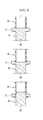
FIG. 4 , three cases of joining methods of thebolt body 10 and thesupport body 20 will be described. - Firstly, referring to
FIG. 4 (A), in acase 1, a lower end of thesupport body 20 is disposed on a center of an upper surface of thehead portion 11 to form a straight line and is welded through rotation friction stirring. - Referring to
FIG. 4 (B), in a case 2, a groove 13 with a predetermined depth of is formed at a center of an upper surface of thehead portion 11, and a lower end of thesupport body 20 is inserted into the groove to be welded by rotation friction stirring, that is, friction welding. - Herein, the
bolt body 10 and thesupport body 20 are disposed along a straight line to maintain a straight structure. - Referring to
FIG. 4 (C), in a case 3, an insertion groove 17 with a predetermined depth is formed on a circumference of an upper surface center of thehead portion 11, and a protruded portion 15 that protrudes upwardly is formed at an inner side of the insertion groove 17. - In a condition in which a lower end of the
support body 20 is inserted into the insertion groove 17 of thehead portion 11, they are welded by rotation friction stirring (friction welding). - In this case, the protruded portion 15 is inserted into an inner side of a lower end portion of the
support body 10, maintains the straightness of thebolt body 10 and thesupport body 20, and improves assembly stiffness. - Here, the
bolt body 10 and thesupport body 20 are welded by friction stirring, but it is not limited thereto, and any methods can be applied thereto as long as thebolt body 10 and thesupport body 20 are strongly joined. - Accordingly, in a
mounting bolt 1 for a sub-frame according to an exemplary embodiment of the present invention as described above, thebolt body 10 and thesupport body 20 are separately formed by cold forging, they are joined by butt-welding, and thesupport body 20 is formed to have a cylindrical hollow space body such that weight is reduced, strength is secured, and cost can be saved, compared to a conventional embodiment. -
FIG. 5 is a cross-sectional view showing a friction welding portion according to an exemplary embodiment of the present invention. - Referring to
FIG. 5 , in afriction welding portion 500, an end portion of asupport body 110 is friction-stir welded to a first undercutgroove 150 of anoutside wall 145 that is formed on ahead portion 140, and abolt body 130 is joined to thesupport body 110. - That is, as shown in (a) of
FIG. 5 , thefriction welding portion 500 forms theoutside wall 145 along a circumference of thehead portion 140 of thebolt body 130 and forms the first undercutgroove 150 in theoutside wall 145 along a lower end circumference thereof. - Further, as shown in (b) of
FIG. 5 , a lower end portion of thesupport body 110 is inserted into an inside of theoutside wall 145. Next, as shown in (c) ofFIG. 5 , a lower end portion of thesupport body 110 is partially melted by friction-stir welding, afirst welding bead 120 flows into the first undercutgroove 150 to be fixed therein, and simultaneously thefirst welding bead 120 is joined to thehead portion 140 of thebolt body 130. -
FIG. 6 is a cross-sectional view showing a friction welding portion according to another exemplary embodiment of the present invention. - Referring to
FIG. 6 , afriction welding portion 500 forms aninsertion groove 160 into which a lower end portion of thesupport body 110 is inserted in ahead portion 140. Theinsertion groove 160 has the same shape as thesupport body 110. That is, theinsertion groove 160 may have a cylinder shape. An interior diameter of theinsertion groove 160 may be larger than an interior diameter of thesupport body 110. - The
friction welding portion 500 has a second undercutgroove 153 that is formed in theinsertion groove 160 in a radial direction. - Further, a lower end portion of the
support body 110 is inserted into theinsertion groove 160 and is friction-stir welded. That is, thesupport body 110 is partially melded by friction-stir welding, asecond welding bead 123 flows into the second undercutgroove 153 to be fixed thereto, and thebead 123 is simultaneously joined to thehead portion 140 of abolt body 130. Thesecond welding bead 123 may be formed at both sides of a lower end portion of thesupport body 110 along the second undercutgroove 153. -
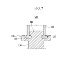
FIG. 7 is a cross-sectional view showing a friction welding portion according to another exemplary embodiment of the present invention. - Referring to
FIG. 7 , afriction welding portion 500 has a protrudedportion 147 that is formed at an upper center of ahead portion 140. In this condition, the protruded portion is inserted into a lower end portion of asupport body 110, can maintain straightness of abolt body 130 and thesupport body 110, and can improve assembly reliability. - The
friction welding portion 500 has a thirdundercut groove 155 that is formed in thehead portion 140 along an exterior circumference of the protrudedportion 147. - Further, a lower end portion of the
support body 110 is inserted into the thirdundercut groove 155 that is formed on thehead portion 140 of thebolt body 130, and is friction-stir welded. That is, a lower end portion of thesupport body 110 is partially melted by friction-stir welding, and athird welding bead 125 flows into the thirdundercut groove 155, and is simultaneously joined to thehead portion 140 of thebolt body 130. - Accordingly, in a mounting bolt for a sub-frame according to the present invention as described above, a lower end portion of the
support body 110 is partially melted by friction-stir welding and flows into the undercutgroove 155 of thefriction welding portion 500 to form a welding bead such that thesupport body 110 and thebolt body 130 are joined, and thus thesupport body 110 and thebolt body 130 can be firmly joined together. - While this invention has been described in connection with what is presently considered to be practical exemplary embodiments, it is to be understood that the invention is not limited to the disclosed embodiments, but, on the contrary, is intended to cover various modifications and equivalent arrangements included within the spirit and scope of the appended claims.
-
- 1 . . . mounting bolt for a sub-frame
- 10, 130 . . . bolt body
- 11, 140 . . . head portion
- 13 . . . groove
- 15, 147 . . . protruded portion
- 17 . . . insertion groove
- 20, 110 . . . support body
- 30 . . . mounting bracket
- H . . . penetration hole
- 500: friction welding portion
- 145: outside wall
- 150, 153, 155 . . . first, second, third undercut grooves
- 120, 123, 125 . . . first, second, third welding beads
- 160: insertion groove
Claims (17)
Applications Claiming Priority (4)
| Application Number | Priority Date | Filing Date | Title |
|---|---|---|---|
| KR1020150096271A KR101829196B1 (en) | 2015-07-07 | 2015-07-07 | Mounting bolt for sub-frame |
| KR10-2015-0096271 | 2015-07-07 | ||
| KR1020150176768A KR101746385B1 (en) | 2015-12-11 | 2015-12-11 | Mounting bolt for sub-frame |
| KR10-2015-0176768 | 2015-12-11 |
Publications (2)
| Publication Number | Publication Date |
|---|---|
| US20170008564A1 true US20170008564A1 (en) | 2017-01-12 |
| US9964136B2 US9964136B2 (en) | 2018-05-08 |
Family
ID=57730036
Family Applications (1)
| Application Number | Title | Priority Date | Filing Date |
|---|---|---|---|
| US15/132,343 Active US9964136B2 (en) | 2015-07-07 | 2016-04-19 | Mounting bolt for sub-frame |
Country Status (1)
| Country | Link |
|---|---|
| US (1) | US9964136B2 (en) |
Cited By (2)
| Publication number | Priority date | Publication date | Assignee | Title |
|---|---|---|---|---|
| US9937961B2 (en) * | 2016-07-18 | 2018-04-10 | Hyundai Motor Company | Mounting device for sub-frame |
| US20220299360A1 (en) * | 2019-08-19 | 2022-09-22 | Casio Computer Co., Ltd. | Window member, method for manufacturing window member, and electronic device |
Citations (11)
| Publication number | Priority date | Publication date | Assignee | Title |
|---|---|---|---|---|
| US2713186A (en) * | 1953-04-20 | 1955-07-19 | George K Garrett Company Inc | Molding-anchorage device for securing trim-molding strips |
| US3187796A (en) * | 1962-06-25 | 1965-06-08 | Multifastener Corp | Multi-purpose pierce and clinch nut |
| US3245449A (en) * | 1964-04-09 | 1966-04-12 | Nat Lock Co | Speaker mounting screw |
| US3467417A (en) * | 1966-11-09 | 1969-09-16 | Standard Pressed Steel Co | Fastener unit |
| US3529508A (en) * | 1969-03-26 | 1970-09-22 | James D Cooksey | Plastic screw fastener combination |
| US3829957A (en) * | 1972-10-30 | 1974-08-20 | Multifastener Corp | Method of assembling a self-fastening nut and a panel |
| US3878599A (en) * | 1969-07-11 | 1975-04-22 | Multifastener Corp | Method of forming a nut and panel assembly |
| US3926236A (en) * | 1972-10-30 | 1975-12-16 | Multifastener Corp | Self-fastening nut, panel assembly and apparatus |
| US4459073A (en) * | 1980-02-02 | 1984-07-10 | Multifastener Corporation | Fasteners with piercing and riveting performance |
| US4850772A (en) * | 1988-04-15 | 1989-07-25 | Trw Inc. | Friction-weldable stud |
| US5382125A (en) * | 1991-05-13 | 1995-01-17 | Duerr; Walter | Screw unit |
Family Cites Families (6)
| Publication number | Priority date | Publication date | Assignee | Title |
|---|---|---|---|---|
| JPH11351224A (en) | 1998-06-05 | 1999-12-24 | Honda Motor Co Ltd | Nut joining method to aluminum work |
| JP2001248621A (en) | 2000-03-07 | 2001-09-14 | Nissan Motor Co Ltd | Welding bolt |
| US6598923B2 (en) | 2000-11-22 | 2003-07-29 | Alcoa Inc. | Joint structure and method for making a joint structure |
| KR100569994B1 (en) | 2003-07-30 | 2006-04-10 | 현대자동차주식회사 | Automotive subframe mounting structure |
| KR20050014281A (en) | 2003-07-30 | 2005-02-07 | 현대자동차주식회사 | Mounting structure of sub frame for automobile |
| KR101459614B1 (en) | 2013-04-30 | 2014-11-07 | 주식회사 신영 | Welding method of vehicle-body mounting part |
-
2016
- 2016-04-19 US US15/132,343 patent/US9964136B2/en active Active
Patent Citations (11)
| Publication number | Priority date | Publication date | Assignee | Title |
|---|---|---|---|---|
| US2713186A (en) * | 1953-04-20 | 1955-07-19 | George K Garrett Company Inc | Molding-anchorage device for securing trim-molding strips |
| US3187796A (en) * | 1962-06-25 | 1965-06-08 | Multifastener Corp | Multi-purpose pierce and clinch nut |
| US3245449A (en) * | 1964-04-09 | 1966-04-12 | Nat Lock Co | Speaker mounting screw |
| US3467417A (en) * | 1966-11-09 | 1969-09-16 | Standard Pressed Steel Co | Fastener unit |
| US3529508A (en) * | 1969-03-26 | 1970-09-22 | James D Cooksey | Plastic screw fastener combination |
| US3878599A (en) * | 1969-07-11 | 1975-04-22 | Multifastener Corp | Method of forming a nut and panel assembly |
| US3829957A (en) * | 1972-10-30 | 1974-08-20 | Multifastener Corp | Method of assembling a self-fastening nut and a panel |
| US3926236A (en) * | 1972-10-30 | 1975-12-16 | Multifastener Corp | Self-fastening nut, panel assembly and apparatus |
| US4459073A (en) * | 1980-02-02 | 1984-07-10 | Multifastener Corporation | Fasteners with piercing and riveting performance |
| US4850772A (en) * | 1988-04-15 | 1989-07-25 | Trw Inc. | Friction-weldable stud |
| US5382125A (en) * | 1991-05-13 | 1995-01-17 | Duerr; Walter | Screw unit |
Cited By (3)
| Publication number | Priority date | Publication date | Assignee | Title |
|---|---|---|---|---|
| US9937961B2 (en) * | 2016-07-18 | 2018-04-10 | Hyundai Motor Company | Mounting device for sub-frame |
| US20220299360A1 (en) * | 2019-08-19 | 2022-09-22 | Casio Computer Co., Ltd. | Window member, method for manufacturing window member, and electronic device |
| US12467782B2 (en) * | 2019-08-19 | 2025-11-11 | Casio Computer Co., Ltd. | Window member, method for manufacturing window member, and electronic device |
Also Published As
| Publication number | Publication date |
|---|---|
| US9964136B2 (en) | 2018-05-08 |
Similar Documents
| Publication | Publication Date | Title |
|---|---|---|
| EP2064080B1 (en) | Tubular b-pillar to stamped rocker joint and method of assembling the same | |
| US9656693B2 (en) | Structure for fastening stiffening bar and method for the same | |
| WO2015146902A1 (en) | Vehicle body side structure | |
| JP6441310B2 (en) | Body frame structure | |
| WO2015146903A1 (en) | Vehicle body side structure | |
| CN106945725B (en) | Extruded multipart subframe for a motor vehicle | |
| JP2008120231A (en) | Auto body structure | |
| CN108136973B (en) | Automotive interior trim materials | |
| US9964136B2 (en) | Mounting bolt for sub-frame | |
| EP3363555A1 (en) | Method for joining mutual members constituting frame structure mounted on automobile, and frame structure mounted on automobile | |
| US10054144B2 (en) | Mounting bolt for sub-frame | |
| JP4523976B2 (en) | Body front structure | |
| US9937961B2 (en) | Mounting device for sub-frame | |
| US7222912B2 (en) | Automotive vehicle body with hydroformed cowl | |
| US20100206676A1 (en) | Shock absorber housing | |
| WO2019049536A1 (en) | Bumper system | |
| KR101829196B1 (en) | Mounting bolt for sub-frame | |
| JP2013133043A (en) | Vehicle body lower part structure | |
| KR101488211B1 (en) | Stud bolt unit | |
| CN108001377B (en) | Fixing structure of vehicle interior trim | |
| US9713980B2 (en) | Body structure pillar reinforcement for spotlight shaft | |
| JP4716780B2 (en) | Steering support beam and instrument panel mounting structure | |
| KR101746385B1 (en) | Mounting bolt for sub-frame | |
| WO2015037153A1 (en) | Assist grip | |
| JP2014162469A (en) | Strut support portion structure of suspension tower for vehicle |
Legal Events
| Date | Code | Title | Description |
|---|---|---|---|
| AS | Assignment |
Owner name: SUNGWOO HITECH CO., LTD., KOREA, REPUBLIC OF Free format text: ASSIGNMENT OF ASSIGNORS INTEREST;ASSIGNORS:NAM, KISUNG;HWANG, JEONG JAE;LEE, MUN YONG;REEL/FRAME:038312/0884 Effective date: 20160415 |
|
| STCF | Information on status: patent grant |
Free format text: PATENTED CASE |
|
| MAFP | Maintenance fee payment |
Free format text: PAYMENT OF MAINTENANCE FEE, 4TH YEAR, LARGE ENTITY (ORIGINAL EVENT CODE: M1551); ENTITY STATUS OF PATENT OWNER: LARGE ENTITY Year of fee payment: 4 |
|
| MAFP | Maintenance fee payment |
Free format text: PAYMENT OF MAINTENANCE FEE, 8TH YEAR, LARGE ENTITY (ORIGINAL EVENT CODE: M1552); ENTITY STATUS OF PATENT OWNER: LARGE ENTITY Year of fee payment: 8 |