US2016366A - Automatic volume control - Google Patents
Automatic volume control Download PDFInfo
- Publication number
- US2016366A US2016366A US570583A US57058331A US2016366A US 2016366 A US2016366 A US 2016366A US 570583 A US570583 A US 570583A US 57058331 A US57058331 A US 57058331A US 2016366 A US2016366 A US 2016366A
- Authority
- US
- United States
- Prior art keywords
- control
- tube
- detector
- grid
- amplifier
- Prior art date
- Legal status (The legal status is an assumption and is not a legal conclusion. Google has not performed a legal analysis and makes no representation as to the accuracy of the status listed.)
- Expired - Lifetime
Links
- 230000000694 effects Effects 0.000 description 5
- 238000000034 method Methods 0.000 description 5
- 230000009471 action Effects 0.000 description 3
- 230000003321 amplification Effects 0.000 description 2
- 230000008878 coupling Effects 0.000 description 2
- 238000010168 coupling process Methods 0.000 description 2
- 238000005859 coupling reaction Methods 0.000 description 2
- 230000003247 decreasing effect Effects 0.000 description 2
- 238000005562 fading Methods 0.000 description 2
- 238000003199 nucleic acid amplification method Methods 0.000 description 2
- 230000008520 organization Effects 0.000 description 2
- 238000010276 construction Methods 0.000 description 1
- 230000003292 diminished effect Effects 0.000 description 1
- 230000004048 modification Effects 0.000 description 1
- 238000012986 modification Methods 0.000 description 1
Images

Classifications
-
- H—ELECTRICITY
- H03—ELECTRONIC CIRCUITRY
- H03G—CONTROL OF AMPLIFICATION
- H03G3/00—Gain control in amplifiers or frequency changers
- H03G3/20—Automatic control
- H03G3/22—Automatic control in amplifiers having discharge tubes
Definitions
- My present invention relates to automatic gain control arrangements, and more particularly to an improved method of, and means for, controlling the gain of a high frequency amplifier, es-
- a radio frequency amplifier which combines the essential features of both the aforementioned systems of the prior art, and yet increases the sharpness of gain control. That is to say, according to the present invention a special tube is utilized in conjunction with the usual detector tube of the radio receiver for simultaneously acting as a direct current amplifier for the direct current component of the detected output, and, additionally, as a rectifier adapted to produce a direct current component for controlling the gain of the radio frequency amplifier, this simultaneous use of the automatic gain control tube resulting in an increased sharpness of control action.
- control tube which consists in disposing a control tube in such relation to the detector and radio frequency amplifler that the control grid of the control tube has a bias established through a path wherein there flows the anode to cathode current of the detector tube, deviation in signal carrier intensity above or below predetermined limits resulting in changes in the now of current through said path whereby the control tube is adapted automatically to vary the gain of the radio frequency amplifier in that direction which will compensate for a deviation from one of said predetermined limits.
- Another important object of the present invention is to provide a radio receiver including a multi-stage radio frequency amplifier, a detector, and an automatic gain control tube, the control 5 grid of said gain control tube being connected through a capacity to the radio frequency output of said amplifier whereby said radio frequency output is rectified by said control tube to provide an additional direct current component of volt- 10 age in the anode circuit of said control tube which direct current voltage is adapted to control the gain of said radio frequency amplifier.
- Still other objects of the invention are to improve generally the efiiciency of automatic gain l5 control circuits, and to particularly provide a gain control arrangement which is not only reliable in operation, but increases the sharpness of control action.
- Fig. l diagrammatically shows a receiving cir- 30 cuit embodying the invention
- Fig. 2 graphically illustrates the relation between signal carrier intensity and bias voltage variation on the detector and on the control tube
- Fig. 3 is a graphic comparison between the op- 35 eration of the present invention andV one of the systems known in the prior art.
- a receiving circuit which embodies the usual 40 grounded antenna circuit A, G, the circuit being coupled, as at M, to the input of a multi-stage radio frequency amplifier.
- the construction of such a radio frequency amplifier is so well known to those skilled in the art that it is not believed 45 necessary to show such an amplifier in more than conventional representation. It is, also, to be clearly understood that the amplifier can be of the tuned type well known to the prior art.
- T Ae amplified output of the radio frequency amplifier 50 is impressed upon the input circuit of a detector tube, as at M1, the variable condenser l being provided for tuning the detector input.
- the condenser I may be arranged for uni-control, in any well known man- 55 ner, with the tuning condensers of the radio frequency amplifier.
- the detector tube 2, shown as a triode for the sake of simplicity, may be an electron discharge tube of any type well known in the art, and is preferably shown as embodying a cathode 2 of the indirect heated type.
- An audio frequency transformer M2 couples the output of the detector to any conventional audio frequency amplifier, of one or more stages, in the usual manner.
- the amplifier may then be followed by any type of utilization means, suchV as head phones, loud speaker and the like.
- a control tube 4 is provided, the tube preferably being a tetrode of the screen grid type and employing a cathode which is indirectly heated.
- the various electrodes of the detector tube and control tube i are energized from a power supply source S.
- the source S, S1 is adapted to receive filtered, rectified alternating current, or where direct current is available from a power line, it may be directly connected to such a direct current power line.
- the terminal S is the positive side of the power source, while the terminal S1 is designated as the negtive side of the source, an intermediate point S2 of the source being grounded.
- a resistor R is disposed between the terminal S and the grounded intermediate point S2, and functions as a voltage -divider for the various electrodes of the receiver requiring positive bias.
- the anode of the detector tube 2 would be connected for the application of a positive potential thereto through a path including the primary coil of the coupling'transformer M2 and a lead which would be connected to a desired point on the resistor R, the latter lead not being shown to preserve simplicity of description.
- a resistor R1 is connected in series with the resistor R, and between the points S2 and S1.
- anode of the control tube i is connected through a fixed resistor RB and a lead 5 to a point on the resistor R1 which is positive with respect to the terminal S1.
- the difference of potential between the point S2 and the point B, to which the anode of tube i is connected, has been designated by the letters Ea and represents the initial bias on the grids of the radio frequency amplifier.
- the screen grid electrode 'i of the control tube is connected by a lead 3 to a point 9 on the resistor R1 which is less positive than the point S, whereby the screen grid electrode is maintained at a less positive potential than the anode of the control tube.
- the cathode it of the latter isY connected by a lead II for adjustable connection to a point I 2 on the resistor R1, the latter being a point of less positive potential than the point il, and of more positive potential than the terminal S1.
- the control grid of the control tube is connected to the terminal S1 through a path which includes the lead I3, the choke coil I4, the resistor I5, the lead Iand the lead il?.
- the portion it of the resistor R1 between the point I2 and the terminal S1 is connected in series with the lead ii, and the drop of potential across the portion I8 has been designated by the reference character E2.
- the drop of potential across the resistor I5 has The been designated by the reference character E71, While the potential of the control grid of the tube l with respect to its cathode i0 has been represented by the reference character E3. It will now be seen that the effective negative bias E3 on the 'control grid of tube 4 is equal to E2-E1, since the control grid of tube 4 is connected through the choke coil i4 to a direct current potential E1 volts above S1 and the cathode of tube 4 is connected to a direct current potential E2 Volts above S1 and E2 is greater'than E1. It will be seen that since E1 is determined by the fiow of anode-cathode current in the detector, E3 will be decreased by a carrier voltage input to the detector.
- the grounded, fixed condensers I9 are employed to provide a path of low impedance to radio frequency and audio frequency currents between the output and input circuits of the detector tube 2.
- the function of the fixed condenser ZQ, in series with the lead i3 and the choke coil I4 is to apply to the control grid of the control tube a carrier voltage input which by rectification in the control tube will cause a control bias for the radio amplifier to be developed in resistor RB.
- tube i develops a rectified output due to this carrier voltage, in addition to its use as a direct current amplifier.
- the control grid of the detector tube 2 is maintained at a negative bais through a path which includes7 the secondary of the coupling transformer M1'in series with the lead I'I and I'I and cathode biasing resistor I5, it being, therefore, seen that the bias of the grid of tube 2 is equal to the direct current voltage furnished by the anode to cathode current of tube 2 flowing through resistor I5.
- the anode of the control tube 4 is connected by means of the leads 2
- the particular manner of connection between these grid circuits and the leads 2l need not be shown since they are too well known to those skilled in the prior art to require any further explanation.
- the voltage produced by the potential drop across the resistor RB has been designated by the'reference character Ec, and represents the gain control bias which is developed during operation of the re DC.
- sharpness of control I refer to the shape of the control characteristic, that is the shape of the curve connecting audio output versus modulated carrier voltage impressed upon the radio frequency ampliner in a receiver system embodying this arrangement. 'Ihis control characteristic is said to be sharp when the range of input carrier voltage required to go from a po-int at which the control action starts to a point beyond which the control characteristic is substantially flat is small.
- a filter system E' usually made up of resistors and capacities in a manner well known to those skilled in the art, is used on the line feeding bias from the control tube back to the amplifier tubes.
- Such a filter is quite necessary whatever the sharpness of control, and is able to distinguish between modulation and fading only upon the basis of the speed of these effects.
- the sharpness and completeness of an automatic volume control characteristic depends upon at least three factors: (l) The rate of increase of direct current bias furnished by the control tube as a function of carrier voltage operating on the control tube, (2) the rate of decrease in amplification of a radio frequency1 stage as a function of bias furnished by the control tube, and (3) the number of stages being controlled.
- the present arrangement provides a means of increasing the first of these factors.
- Fig. 2 there is graphically shown the relation between the potentials E2, E1 and E3 as the carrier input E0 is increased. E3, the negative bias voltage of the control tube is thus seen to ecrease with increasing carrier input since E3:E2-E1.
- the control tube will, therefore, operate as a direct current amplifier, its input being derived from changes in the direct current bias of the detector tube, and its output being a direct current voltage across RB. In addition it will operate as a rectifier as shown in Fig. 3.
- Fig. 3 there is shown a graphic comparison betweentheoperationof the present arrangement and the rectifier arrangement of the prior art.
- Carrier voltages En carrier are plotted against ipRB A. V. C. output for different values of control grid bias E3 on the control tube.
- the dotted line D shows the variation, according to my present invention of Voltage Ec with carrier voltage En. Without the variation of E3 bias on the control tube d, the A. V. C. voltage Ec would vary as the 12 curve with the carrier.
- the present arrangement provides for a sharpness of control not possible without the utilization of variation of E3 bias on the control tube.
- a radio frequency amplifier means connecting the anode of the control tube to an amplifier grid, means connecting the control grid of the contro-1 tube to a biasing path connected between thecathode and anode of the detector tube whereby the direct current potential difference between 1o.
- control grid and cathode of said control tube is determined by the direct current potential drop across said biasing path, and means impressing the output of said radio frequency amplifier upon the control grid circuit of said control tube.
- a radio frequency amplifier In combination, a radio frequency amplifier, a detector tube, a control tube, means for connecting the anode of the control tube to an amplifier grid, and means for connecting the control grid of the control tube to a biasing path connected between the cathode and anode of the detector tube, said path including a high radio frequency impedance connected between the said control grid and the cathode of said detector tube, and a capacity for impressing the radio frequency inout to the detector upon said control grid connected between the detector grid and said impedance.
- a radio frequency amplifier a detector tube, a control tube, means for connecting the anode of the control tube to an amplifier grid, means for connecting the control grid of the control tube to a biasing path connected between the cathode and anode of the detector tube whereby the direct current potential diiierence between the control grid and cathode of said control tube is determined by the direct current potential drop across said biasing path, the cathode of the control tube being connected to a point on said path which is more positive than the point to which said control grid is connected, and means impressing the output of said radio frequency amplifier upon the control grid circuit of said control tube.
- a radio frequency amplifier a detecto-r tube, a control tube, means for connecting the anode of the control tube to an ampliiier grid, and means for connecting the con trol grid and cathode of the control tube to a biasing path connected between the cathode and anode of the detector tube whereby the direct current potential difference between the control grid and cathode of said control tube is determined by th'e direct current potential drop across said biasing path, said path including a resistor -connected between the anode and cathode of the detector tube, and means impressing upon the control grid of said control tube the carrier voltage output of said radio frequency amplifier.
- a radio frequency amplier, detector tube, and control tube means adapting the flow of direct current in the anode circuit of said control tube for providing a bias to control the gain of .said radio frequency amplifier, means in the anode-cathode circuit of said detector providing modulation frequency output, means in the anode-cathode circuit of said detector tube providing a direct current potential that is a function of the output of said radio frequency amplifier, means impressing said direct current potential as a bias in the control grid circuit of said control tube, and means impressing the output of the radio frequency amplifier upon the control grid of said control tube, whereby said ocntrol tube functions simultaneously as a direct current amplifier and as a rectier, to maintain the carrier voltage output of said radio amplifier within narrow limits overa wide range of carrier voltage input toy said amplifier.
- An automatic volume control arrangement for a radio receiver which receiver includes at least super-audible frequency amplifier and detector, said arrangemer comprising a volume control tube having at least one output electrode and at least one input electrode, a direct current connection between the output electrode and the amplifier such that a. bias is provided to control the amplifier gain, a direct current connection between the said input electrode and a point in the cathode-anode circuit of said detector, the
- said last circuit including an impedance for providing a bias for said input electrode which is a. function of the carrier voltage output of said amplifier, and a connection, of high impedance to direct current, between said input electrode and a point between the amplifier and detector to 'inpress said carrier voltage on said input electrode for rectification.
- An automatic volume control arrangement for a radio receiver which receiver includes at least a super-audible frequency amplifier detector, said arrangement comprising a volume control tube having at least one output electrode and at least one input electrode, a direct current connection between the output electrode and the amplifier such that a bias is provided to conrol the amplifier gain, a direct current connection between the said input electrode and a point in the cathode-anode circuit of detector, the said last circuit incl ing an impedance for providing a bias for said input Yelectrode which is a function of the carrier voltage output of said amplifier, and a connection, of high impedance to direct current, between said input electrode and a point between the amplifier and detector to impress carrier voltage on said input electrode for rectification, said carrier volte output being maintained within narrow limits over a wide range or carrier voltage input to said amplifier.
- a method which consists in collecting modulated carrier frequency energy, amplifying the collected energy, detecting the amplified energy, amplifying the direct current component of the detected energy, rectifying a portion of the amplified carrier energy simultaneously with the amplincation oi said direct current component, and varying the amplication of the collected carrier energy with the said amplified direct current component and said rectified carrier energy in a direction such that the amplified carrier frequency voltage is maintained within narrow7 limits over a wide range of collected carrier frequency voltage.
- An automatic volume control arrangement for a receiver which receiver includes a high frequency amplifier and detector, comprisingr a control tube, a condenser connecting the control grids of the detector and control tube, a detect-or grid biasing resistor in the space current path of the detector, a radio frequency choke connected between cne side of the resistor and a point intermediate the condenser and the control tube grid, a Voltage supply resistor, the other side of said biasing resistor being connected to a negative point of the supply resistor, the control tube cathode being connected to a more positive point on the supply resistor, the control tube anode being connected to a point on the supply resistor more positive than said last two points, and a conductive gain control connection between the control tube anode and said amplifier.
- a receiver of the type including a radio frequency amplifier, a detector, and means including a rectifier for automatically biasing said amplifier to control the gain thereof 10 in accordance with the strength of received radio waves
- the method which comprises initially biasing said amplifier for maximum gain, initially biasing said rectifier to render the same inoperative, and reducing the rectifier bias to render the same operative when the received radio waves reach that value which, with maximum amplifier gain, produces a predetermined value of radio input on the detector.
- a signal amplifier In a receiving system, a signal amplifier, a detector tube provided with a signal grid, cathode and anode, an impedance in the space current path of the detector tube, the signal grid or the detector being connected to a point of said impedance which.
- an amplifier gain control tube provi-d with at least a grid, cathode and anode, means for connecting the control tube grid to the said detector cathode, a connection from the control tube catho-:le tc said point on the said impedance, an adjustable source of voltage for said control tube whereby the initial point of operation thereof with respect to signal amplitude may be predetermined, a gain control connection between the control tube anode and said signal amplifier, and a signal path connected between the detector signal grid and the control tube grid.
- a signal amplifier In a receiving system, a signal amplifier,
- a detector tube provided with a signal grid, cathode and anode, an impedance in the space cur- 40 rent path of the detector tube, the signal grid of the detector being connected to a. point of said impedance which is negative with respect to the cathode potential, an amplifier gain control tube provided with at least a grid, cathode and anode, means for connecting the control tube grid to the said detector cathode through a signal frequency choke coil, a connection 'from the control tube cathode to said point on the said impedance, a signal path connected between the detector signal grid and the control tube grid, and a gain control connection between the control tube anode and said signal amplifier.
- a signal ampli er In a receiving system, a signal ampli er,
- a detector tube provided with a signal grid, cathode and anode, impedance in the space current path of the detector tube, the signal grid of the detector being connected to a point of said impedance which is negative with respect to the cathode potential
- an ampliiier gain control tube provided with at least a grid, cathode and anode, means for connecting the control tube grid to the said detector cathode, a connection from the control tube cathode to said point on the said impedance, a signal path connected between the detector signal grid and the control tube grid, an impedance connected between the control tube anode and cathode, and a gain control connection between the control tube anode and said signal amplifier.
Landscapes
- Control Of Amplification And Gain Control (AREA)
- Circuits Of Receivers In General (AREA)
Description
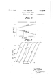
@DE 8, 1935. P. FARNHAM 2,016,366
I AUTOMATIC VOLUME CONTROL Filed Oct. 23, 1951 2. Sheets-Sheet l w lNvENToR |||||1- PAUL o. FARNHAM BY W A`TTORNEY @t 8, 1935,. 1:` Q FARNHAM 2,016,366
AUTOMATI C VOLUME CONTROL Filed Oct. 23, 1931 2 Sheets-Sheet 2 zp/ig AL/C 007/207 O fo CARB/ER INVENTOR PAUL 0. FARN HAM BY y ATTORNEY Patented Oct. 8, 1935 UNITED STATES PATENT OFFICE AUTOMATIC VOLUME CONTROL Delaware Application October 23, 1931, Serial No. 570,583
13 Claims.
My present invention relates to automatic gain control arrangements, and more particularly to an improved method of, and means for, controlling the gain of a high frequency amplifier, es-
pecially where such amplifiers are utilized in radio receivers.
Automatic gain control for the radio frequency amplifiers of radio receivers has been employed to a great extent in the past. Such gain control systems of the prior art usually employ the direct current component of the detector output for automatically controlling the gain of the radio frequency amplifier. In some systems a direct current amplifier is disposed between the controlled amplier and the detector circuit. In still other systems a special automatic volume control tube has been employed as a rectifier operating from the carrier voltage at the output of the radio frequency amplifier and providing a direct current component to be utilized for controlling the gain of the radio frequency amplifier. In all these systems, however, the control of the radio frequency amplier has not been ideally sharp.
.Now, I have devised an arrangement for automatically controlling the gain of a radio frequency amplifier which combines the essential features of both the aforementioned systems of the prior art, and yet increases the sharpness of gain control. That is to say, according to the present invention a special tube is utilized in conjunction with the usual detector tube of the radio receiver for simultaneously acting as a direct current amplifier for the direct current component of the detected output, and, additionally, as a rectifier adapted to produce a direct current component for controlling the gain of the radio frequency amplifier, this simultaneous use of the automatic gain control tube resulting in an increased sharpness of control action.
It may therefore be stated that it is one of the main objects of my present invention to provide a method of, and means for automatically controlling the gain of a radio frequency amplifier,
which consists in disposing a control tube in such relation to the detector and radio frequency amplifler that the control grid of the control tube has a bias established through a path wherein there flows the anode to cathode current of the detector tube, deviation in signal carrier intensity above or below predetermined limits resulting in changes in the now of current through said path whereby the control tube is adapted automatically to vary the gain of the radio frequency amplifier in that direction which will compensate for a deviation from one of said predetermined limits.
Another important object of the present invention is to provide a radio receiver including a multi-stage radio frequency amplifier, a detector, and an automatic gain control tube, the control 5 grid of said gain control tube being connected through a capacity to the radio frequency output of said amplifier whereby said radio frequency output is rectified by said control tube to provide an additional direct current component of volt- 10 age in the anode circuit of said control tube which direct current voltage is adapted to control the gain of said radio frequency amplifier.
Still other objects of the invention are to improve generally the efiiciency of automatic gain l5 control circuits, and to particularly provide a gain control arrangement which is not only reliable in operation, but increases the sharpness of control action.
rllhe novelV features which I believe to be char- 20 acteristic of my invention are set forth in particularity in the appended claims, the invention itself, however, as to both its organization and method of operation will best be understood by reference to the following description taken in 25 connection with the drawings in which I have indicated diagrammatically one circuit arrangement for carrying my invention into effect.
In the drawings,
Fig. l diagrammatically shows a receiving cir- 30 cuit embodying the invention,
Fig. 2 graphically illustrates the relation between signal carrier intensity and bias voltage variation on the detector and on the control tube,
Fig. 3 is a graphic comparison between the op- 35 eration of the present invention andV one of the systems known in the prior art.
Referring to the accompanying drawings there is shown in Fig. 1, in diagrammatic manner, a receiving circuit which embodies the usual 40 grounded antenna circuit A, G, the circuit being coupled, as at M, to the input of a multi-stage radio frequency amplifier. The construction of such a radio frequency amplifier is so well known to those skilled in the art that it is not believed 45 necessary to show such an amplifier in more than conventional representation. It is, also, to be clearly understood that the amplifier can be of the tuned type well known to the prior art. T Ae amplified output of the radio frequency amplifier 50 is impressed upon the input circuit of a detector tube, as at M1, the variable condenser l being provided for tuning the detector input. It is to be understood that the condenser I may be arranged for uni-control, in any well known man- 55 ner, with the tuning condensers of the radio frequency amplifier. The detector tube 2, shown as a triode for the sake of simplicity, may be an electron discharge tube of any type well known in the art, and is preferably shown as embodying a cathode 2 of the indirect heated type.
An audio frequency transformer M2 couples the output of the detector to any conventional audio frequency amplifier, of one or more stages, in the usual manner. The amplifier may then be followed by any type of utilization means, suchV as head phones, loud speaker and the like. The aforementioned general features of the receiver are so well known to those skilled in the art that they need not be described in any further details, except to point out that they may be replaced by any other elements adapted to perform the Same functions.
In order to provide automatic control of the gain of the radio frequency amplifier a control tube 4 is provided, the tube preferably being a tetrode of the screen grid type and employing a cathode which is indirectly heated. The various electrodes of the detector tube and control tube i are energized from a power supply source S. It is to be understood that the source S, S1 is adapted to receive filtered, rectified alternating current, or where direct current is available from a power line, it may be directly connected to such a direct current power line. It will be noted that the terminal S is the positive side of the power source, while the terminal S1 is designated as the negtive side of the source, an intermediate point S2 of the source being grounded.
A resistor R is disposed between the terminal S and the grounded intermediate point S2, and functions as a voltage -divider for the various electrodes of the receiver requiring positive bias. For example, the anode of the detector tube 2 would be connected for the application of a positive potential thereto through a path including the primary coil of the coupling'transformer M2 and a lead which would be connected to a desired point on the resistor R, the latter lead not being shown to preserve simplicity of description.
A resistor R1 is connected in series with the resistor R, and between the points S2 and S1. anode of the control tube i is connected through a fixed resistor RB and a lead 5 to a point on the resistor R1 which is positive with respect to the terminal S1. The difference of potential between the point S2 and the point B, to which the anode of tube i is connected, has been designated by the letters Ea and represents the initial bias on the grids of the radio frequency amplifier. The screen grid electrode 'i of the control tube is connected by a lead 3 to a point 9 on the resistor R1 which is less positive than the point S, whereby the screen grid electrode is maintained at a less positive potential than the anode of the control tube.
The cathode it of the latter isY connected by a lead II for adjustable connection to a point I 2 on the resistor R1, the latter being a point of less positive potential than the point il, and of more positive potential than the terminal S1. The control grid of the control tube is connected to the terminal S1 through a path which includes the lead I3, the choke coil I4, the resistor I5, the lead Iand the lead il?. The portion it of the resistor R1 between the point I2 and the terminal S1 is connected in series with the lead ii, and the drop of potential across the portion I8 has been designated by the reference character E2.
The drop of potential across the resistor I5 has The been designated by the reference character E71, While the potential of the control grid of the tube l with respect to its cathode i0 has been represented by the reference character E3. It will now be seen that the effective negative bias E3 on the 'control grid of tube 4 is equal to E2-E1, since the control grid of tube 4 is connected through the choke coil i4 to a direct current potential E1 volts above S1 and the cathode of tube 4 is connected to a direct current potential E2 Volts above S1 and E2 is greater'than E1. It will be seen that since E1 is determined by the fiow of anode-cathode current in the detector, E3 will be decreased by a carrier voltage input to the detector.
The grounded, fixed condensers I9 are employed to provide a path of low impedance to radio frequency and audio frequency currents between the output and input circuits of the detector tube 2. The function of the fixed condenser ZQ, in series with the lead i3 and the choke coil I4 is to apply to the control grid of the control tube a carrier voltage input which by rectification in the control tube will cause a control bias for the radio amplifier to be developed in resistor RB. Y
Thus, tube i develops a rectified output due to this carrier voltage, in addition to its use as a direct current amplifier.
The control grid of the detector tube 2 is maintained at a negative bais through a path which includes7 the secondary of the coupling transformer M1'in series with the lead I'I and I'I and cathode biasing resistor I5, it being, therefore, seen that the bias of the grid of tube 2 is equal to the direct current voltage furnished by the anode to cathode current of tube 2 flowing through resistor I5.
The anode of the control tube 4 is connected by means of the leads 2| to the grid circuits of the radio frequency amplifier stages. The particular manner of connection between these grid circuits and the leads 2l need not be shown since they are too well known to those skilled in the prior art to require any further explanation. The voltage produced by the potential drop across the resistor RB has been designated by the'reference character Ec, and represents the gain control bias which is developed during operation of the re ceiver. Y
The operation of the present gain control arrangement will now be clear from the aforegoing description and the drawings. if the signal carrier intensity, represented by the reference character Eo, increases, there will be produced both by rectification and by the decrease in E3 due to increasing E1 an'increased flow of current in the plate circuit of the control tube 4. This increased flow of plate current results in an increased drop of potential across the resistor RB with the re sult that the value of Ec becomes greater, and necessarily increases the bias on the of the amplifier tubes thereby reducing the radio frequency amplification and compensating for the increase of carrier voltage above the predetermined upper limit.
The increase of plate current fiow in the gain control tube results because of two factors. One of these factors involves a rectification of the signal voltage Eo applied to the control tube through condenser 20, and the other factor involves the decreasing bias E3 on the grid of the gain control tube. It will be readily seen that with increased values of Eo there will occur a greater liowV of direct current through the path between the anode and cathode of the detector tube, which.path includes the resistors R, R1 and l5. In other Words, when En increases, the value of E1 increases, and hence, since E3 is equal to E12-E1, the value of E3 is diminished with the result that a greater value of current is produced in the plate 'circuit of the tube 4.
means of the present arrangement a more rapid increase of plate current flow in the gain control tube with En increase is produced than either the direct current ampliiier or rectifier system of gain control used alone, hence increasing the sharpness of control. By sharpness of control I refer to the shape of the control characteristic, that is the shape of the curve connecting audio output versus modulated carrier voltage impressed upon the radio frequency ampliner in a receiver system embodying this arrangement. 'Ihis control characteristic is said to be sharp when the range of input carrier voltage required to go from a po-int at which the control action starts to a point beyond which the control characteristic is substantially flat is small. In order to distinguish between modulation effects and fading effects a filter system E' usually made up of resistors and capacities in a manner well known to those skilled in the art, is used on the line feeding bias from the control tube back to the amplifier tubes. Such a filter is quite necessary whatever the sharpness of control, and is able to distinguish between modulation and fading only upon the basis of the speed of these effects.
The sharpness and completeness of an automatic volume control characteristic depends upon at least three factors: (l) The rate of increase of direct current bias furnished by the control tube as a function of carrier voltage operating on the control tube, (2) the rate of decrease in amplification of a radio frequency1 stage as a function of bias furnished by the control tube, and (3) the number of stages being controlled. The present arrangement provides a means of increasing the first of these factors.
In Fig. 2 there is graphically shown the relation between the potentials E2, E1 and E3 as the carrier input E0 is increased. E3, the negative bias voltage of the control tube is thus seen to ecrease with increasing carrier input since E3:E2-E1. The control tube will, therefore, operate as a direct current amplifier, its input being derived from changes in the direct current bias of the detector tube, and its output being a direct current voltage across RB. In addition it will operate as a rectifier as shown in Fig. 3.
In Fig. 3 there is shown a graphic comparison betweentheoperationof the present arrangement and the rectifier arrangement of the prior art. Carrier voltages En carrier are plotted against ipRB A. V. C. output for different values of control grid bias E3 on the control tube. Thus, the dotted line D shows the variation, according to my present invention of Voltage Ec with carrier voltage En. Without the variation of E3 bias on the control tube d, the A. V. C. voltage Ec would vary as the 12 curve with the carrier. There will be observed from Fig. 3 that the present arrangement provides for a sharpness of control not possible without the utilization of variation of E3 bias on the control tube.
While I have indicated and described one arrangement for carrying my invention into effect, it willbe apparent to one skilled in the art that my invention is by no means limited to the particular organization shown and described, but that many modifications may be made without `departing from the scope of my invention as set forth in the appended claims.
What I claim is:
l. In combination, a radio frequency amplifier, a detector tube, a control tube, means connecting the anode of the control tube to an amplifier grid, means connecting the control grid of the contro-1 tube to a biasing path connected between thecathode and anode of the detector tube whereby the direct current potential difference between 1o.
the control grid and cathode of said control tube is determined by the direct current potential drop across said biasing path, and means impressing the output of said radio frequency amplifier upon the control grid circuit of said control tube.
2. In combination, a radio frequency amplifier, a detector tube, a control tube, means for connecting the anode of the control tube to an amplifier grid, and means for connecting the control grid of the control tube to a biasing path connected between the cathode and anode of the detector tube, said path including a high radio frequency impedance connected between the said control grid and the cathode of said detector tube, and a capacity for impressing the radio frequency inout to the detector upon said control grid connected between the detector grid and said impedance.
3. In combination, a radio frequency amplifier, a detector tube, a control tube, means for connecting the anode of the control tube to an amplifier grid, means for connecting the control grid of the control tube to a biasing path connected between the cathode and anode of the detector tube whereby the direct current potential diiierence between the control grid and cathode of said control tube is determined by the direct current potential drop across said biasing path, the cathode of the control tube being connected to a point on said path which is more positive than the point to which said control grid is connected, and means impressing the output of said radio frequency amplifier upon the control grid circuit of said control tube.
4. In combination, a radio frequency amplifier, a detecto-r tube, a control tube, means for connecting the anode of the control tube to an ampliiier grid, and means for connecting the con trol grid and cathode of the control tube to a biasing path connected between the cathode and anode of the detector tube whereby the direct current potential difference between the control grid and cathode of said control tube is determined by th'e direct current potential drop across said biasing path, said path including a resistor -connected between the anode and cathode of the detector tube, and means impressing upon the control grid of said control tube the carrier voltage output of said radio frequency amplifier.
5. In combination, a radio frequency amplier, detector tube, and control tube, means adapting the flow of direct current in the anode circuit of said control tube for providing a bias to control the gain of .said radio frequency amplifier, means in the anode-cathode circuit of said detector providing modulation frequency output, means in the anode-cathode circuit of said detector tube providing a direct current potential that is a function of the output of said radio frequency amplifier, means impressing said direct current potential as a bias in the control grid circuit of said control tube, and means impressing the output of the radio frequency amplifier upon the control grid of said control tube, whereby said ocntrol tube functions simultaneously as a direct current amplifier and as a rectier, to maintain the carrier voltage output of said radio amplifier within narrow limits overa wide range of carrier voltage input toy said amplifier.
6. An automatic volume control arrangement for a radio receiver, which receiver includes at least super-audible frequency amplifier and detector, said arrangemer comprising a volume control tube having at least one output electrode and at least one input electrode, a direct current connection between the output electrode and the amplifier such that a. bias is provided to control the amplifier gain, a direct current connection between the said input electrode and a point in the cathode-anode circuit of said detector, the
said last circuit including an impedance for providing a bias for said input electrode which is a. function of the carrier voltage output of said amplifier, and a connection, of high impedance to direct current, between said input electrode and a point between the amplifier and detector to 'inpress said carrier voltage on said input electrode for rectification.
'7. An automatic volume control arrangement for a radio receiver, which receiver includes at least a super-audible frequency amplifier detector, said arrangement comprising a volume control tube having at least one output electrode and at least one input electrode, a direct current connection between the output electrode and the amplifier such that a bias is provided to conrol the amplifier gain, a direct current connection between the said input electrode and a point in the cathode-anode circuit of detector, the said last circuit incl ing an impedance for providing a bias for said input Yelectrode which is a function of the carrier voltage output of said amplifier, and a connection, of high impedance to direct current, between said input electrode and a point between the amplifier and detector to impress carrier voltage on said input electrode for rectification, said carrier volte output being maintained within narrow limits over a wide range or carrier voltage input to said amplifier.
8. A method which consists in collecting modulated carrier frequency energy, amplifying the collected energy, detecting the amplified energy, amplifying the direct current component of the detected energy, rectifying a portion of the amplified carrier energy simultaneously with the amplincation oi said direct current component, and varying the amplication of the collected carrier energy with the said amplified direct current component and said rectified carrier energy in a direction such that the amplified carrier frequency voltage is maintained within narrow7 limits over a wide range of collected carrier frequency voltage.
9. An automatic volume control arrangement for a receiver, which receiver includes a high frequency amplifier and detector, comprisingr a control tube, a condenser connecting the control grids of the detector and control tube, a detect-or grid biasing resistor in the space current path of the detector, a radio frequency choke connected between cne side of the resistor and a point intermediate the condenser and the control tube grid, a Voltage supply resistor, the other side of said biasing resistor being connected to a negative point of the supply resistor, the control tube cathode being connected to a more positive point on the supply resistor, the control tube anode being connected to a point on the supply resistor more positive than said last two points, and a conductive gain control connection between the control tube anode and said amplifier.
10. In the operation oi a receiver of the type including a radio frequency amplifier, a detector, and means including a rectifier for automatically biasing said amplifier to control the gain thereof 10 in accordance with the strength of received radio waves, the method which comprises initially biasing said amplifier for maximum gain, initially biasing said rectifier to render the same inoperative, and reducing the rectifier bias to render the same operative when the received radio waves reach that value which, with maximum amplifier gain, produces a predetermined value of radio input on the detector.
ll. In a receiving system, a signal amplifier, a detector tube provided with a signal grid, cathode and anode, an impedance in the space current path of the detector tube, the signal grid or the detector being connected to a point of said impedance which. .is negative with respect to the cathode potential, an amplifier gain control tube provi-d with at least a grid, cathode and anode, means for connecting the control tube grid to the said detector cathode, a connection from the control tube catho-:le tc said point on the said impedance, an adjustable source of voltage for said control tube whereby the initial point of operation thereof with respect to signal amplitude may be predetermined, a gain control connection between the control tube anode and said signal amplifier, and a signal path connected between the detector signal grid and the control tube grid.
l2. In a receiving system, a signal amplifier,
a detector tube provided with a signal grid, cathode and anode, an impedance in the space cur- 40 rent path of the detector tube, the signal grid of the detector being connected to a. point of said impedance which is negative with respect to the cathode potential, an amplifier gain control tube provided with at least a grid, cathode and anode, means for connecting the control tube grid to the said detector cathode through a signal frequency choke coil, a connection 'from the control tube cathode to said point on the said impedance, a signal path connected between the detector signal grid and the control tube grid, and a gain control connection between the control tube anode and said signal amplifier.
13. In a receiving system, a signal ampli er,
a detector tube provided with a signal grid, cathode and anode, impedance in the space current path of the detector tube, the signal grid of the detector being connected to a point of said impedance which is negative with respect to the cathode potential, an ampliiier gain control tube provided with at least a grid, cathode and anode, means for connecting the control tube grid to the said detector cathode, a connection from the control tube cathode to said point on the said impedance, a signal path connected between the detector signal grid and the control tube grid, an impedance connected between the control tube anode and cathode, and a gain control connection between the control tube anode and said signal amplifier.
PAUL O. FARNHAM.
Priority Applications (1)
| Application Number | Priority Date | Filing Date | Title |
|---|---|---|---|
| US570583A US2016366A (en) | 1931-10-23 | 1931-10-23 | Automatic volume control |
Applications Claiming Priority (1)
| Application Number | Priority Date | Filing Date | Title |
|---|---|---|---|
| US570583A US2016366A (en) | 1931-10-23 | 1931-10-23 | Automatic volume control |
Publications (1)
| Publication Number | Publication Date |
|---|---|
| US2016366A true US2016366A (en) | 1935-10-08 |
Family
ID=24280222
Family Applications (1)
| Application Number | Title | Priority Date | Filing Date |
|---|---|---|---|
| US570583A Expired - Lifetime US2016366A (en) | 1931-10-23 | 1931-10-23 | Automatic volume control |
Country Status (1)
| Country | Link |
|---|---|
| US (1) | US2016366A (en) |
-
1931
- 1931-10-23 US US570583A patent/US2016366A/en not_active Expired - Lifetime
Similar Documents
| Publication | Publication Date | Title |
|---|---|---|
| US2144304A (en) | Delayed automatic gain control circuit | |
| US2144605A (en) | Automatic selective fading control circuit | |
| US2344618A (en) | Radio air raid warning system | |
| US2264019A (en) | Signal-translating system | |
| US2018982A (en) | Delayed automatic volume control circuit | |
| US2016366A (en) | Automatic volume control | |
| US2420518A (en) | Power reduction circuit for radio receivers | |
| US2172160A (en) | Delayed automatic volume control | |
| US2366565A (en) | Audio-frequency amplifier | |
| US2507145A (en) | Peak limiting expanding amplifier | |
| US2041150A (en) | Automatic gain control | |
| US2083243A (en) | Automatic gain control and noise suppression circuits | |
| US2135949A (en) | Noise suppressor circuit | |
| US2144921A (en) | Automatic volume control | |
| US1971646A (en) | Radio receiving system | |
| US2076803A (en) | Noise suppressor circuit | |
| US1889018A (en) | Volume control | |
| US2083232A (en) | Automatic selectivity control system | |
| US2048738A (en) | Detector circuit | |
| US2231377A (en) | Noise limiter circuit | |
| US2082961A (en) | Automatic gain control circuit | |
| US2103865A (en) | Superheterodyne automatic gain control system | |
| US2186130A (en) | Detecting system | |
| US2078072A (en) | Radio receiver | |
| US2367357A (en) | Volume control |