US2016337A - Combustion engine - Google Patents
Combustion engine Download PDFInfo
- Publication number
- US2016337A US2016337A US548813A US54881331A US2016337A US 2016337 A US2016337 A US 2016337A US 548813 A US548813 A US 548813A US 54881331 A US54881331 A US 54881331A US 2016337 A US2016337 A US 2016337A
- Authority
- US
- United States
- Prior art keywords
- fuel
- engine
- carburetor
- air
- valve
- Prior art date
- Legal status (The legal status is an assumption and is not a legal conclusion. Google has not performed a legal analysis and makes no representation as to the accuracy of the status listed.)
- Expired - Lifetime
Links
Images


Classifications
-
- F—MECHANICAL ENGINEERING; LIGHTING; HEATING; WEAPONS; BLASTING
- F01—MACHINES OR ENGINES IN GENERAL; ENGINE PLANTS IN GENERAL; STEAM ENGINES
- F01M—LUBRICATING OF MACHINES OR ENGINES IN GENERAL; LUBRICATING INTERNAL COMBUSTION ENGINES; CRANKCASE VENTILATING
- F01M3/00—Lubrication specially adapted for engines with crankcase compression of fuel-air mixture or for other engines in which lubricant is contained in fuel, combustion air, or fuel-air mixture
-
- F—MECHANICAL ENGINEERING; LIGHTING; HEATING; WEAPONS; BLASTING
- F02—COMBUSTION ENGINES; HOT-GAS OR COMBUSTION-PRODUCT ENGINE PLANTS
- F02M—SUPPLYING COMBUSTION ENGINES IN GENERAL WITH COMBUSTIBLE MIXTURES OR CONSTITUENTS THEREOF
- F02M17/00—Carburettors having pertinent characteristics not provided for in, or of interest apart from, the apparatus of preceding main groups F02M1/00 - F02M15/00
- F02M17/14—Carburettors with fuel-supply parts opened and closed in synchronism with engine stroke ; Valve carburettors
- F02M17/145—Carburettors with fuel-supply parts opened and closed in synchronism with engine stroke ; Valve carburettors the valve being opened by the pressure of the passing fluid
-
- F—MECHANICAL ENGINEERING; LIGHTING; HEATING; WEAPONS; BLASTING
- F02—COMBUSTION ENGINES; HOT-GAS OR COMBUSTION-PRODUCT ENGINE PLANTS
- F02B—INTERNAL-COMBUSTION PISTON ENGINES; COMBUSTION ENGINES IN GENERAL
- F02B75/00—Other engines
- F02B75/02—Engines characterised by their cycles, e.g. six-stroke
- F02B2075/022—Engines characterised by their cycles, e.g. six-stroke having less than six strokes per cycle
- F02B2075/025—Engines characterised by their cycles, e.g. six-stroke having less than six strokes per cycle two
Definitions
- Patented Oct. 8, 1935 UNITED STATES COMBUSTION ENGINE John Milmlasek, Newton, Iowa, assignor to The Maytag Company, Newton, Iowa, a corporation of Delaware Original application September 27, 1929, Serial No. 395,518, new Patent No. 1,973,218, September 11, 1934. Divided and this application July 6, 1931, Serial No. 548.813
- the present invention relates to novel improvements in internal combustion engines, and more particularly in the carburetor construction and the means and method of lubricating the engine.
- the present application is a division of my co pending application Serial No. 395,518, filed September 27, 1929, issued September 11, 1934, as Patent No. 1,973,218.
- a carburetor construction in which the fuel is drawn from the fuel tank into the base or lower portion of the engine and through the lubricant in the crank case. This fuel is drawn into the carburetor by the same suction which draws in the air for forming the combustible By reason of this construction and arrangement, flooding of the crank case is prevented.
- a further object is the provision of a construction whereby the amount or supply of air wh'ch is sucked into the carburetor is constant, while the amount of fuel may be adjusted for obtaining the proper and most efllcient mixture for carburction and smooth running of the engine.
- Another object of the invention is the provision of a carburetor divided into a suction or air compartment located in the upper port'on, and a mixing compartment located in the lower portion thereof.
- An air valve is located intermediate these two compartments.
- a further object s the provision of a novel carburetor construction which eliminates the necessity or use of a deflooder.
- a deflooder was employed
- the fuel in the fuel tank would become contaminated by the black heavy mixture of lubricant and fuel from the base of the crank case, and by water which accumulates from humid air.
- Another object of the invention is the means and method of lubricating all working and wearing parts of the engine.
- the method comprehends the addition or admixture of lubricant with the fuel, and delivering this lubricant to the various working parts of the engine.
- the invention further comprehends the method of delivering the lubricant and fuel, or an admixture thereof, to the crank case of the engine.
- This method contemplates delivering the lubricant and fuel from the fuel supply tank to the carburetor during the suction stroke, there mixing the requisite amount of fuel and air for forming the combustible mixture, vaporizing the fuel, and depositing the lubricant and its spray on all working parts of the engine, including the bearings, starter, magneto flywheel, cylinder, piston, etc.
- This lubricant is deposited either by drect contact with these parts, or by reason of the suction and compression forces existing in the crank case.
- ribs, deflectors, oil holes and grooves are provided. Additional means or bypasses are provided for leading away the excess lubricant, and returning the same to the crank case and fuel supply tank.
- Still another object of the invention is to pro- Although the carburetor and lubricating construction is disclosed and described as primarily adapted for two-cycle engines, it is to be understood that the invention is not limited thereto,
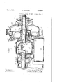
- Fig. 1 is a view in side elevation of the internal combustion engine.
- Fig. 2 is a transverse vertical cross sectional view taken in a plane represen ed by the line 2-2 of Fig. 1.
- Fig. 3 is a view in vertical cross section taken in a plane represented by the line 3--3 of Fig. 2.
- the engine construction is shown as provided with a base or casting forming a fuel supply tank I, and provided with frame extensions 2 and 3 for mounting the same upon operating mechanism to be driven thereby.
- the fuel tank I is provided with an opening adapted to be closed by a threaded plug 4.
- this plug is provided adjacent the upper surface of the fuel supply tank to permit filling of the tank, and at the same time the position of the plug is such that the tank cannot be filled beyond the stage of o' eri'lowing.
- a drain cock 5 is provided in the base of the fuel supply tank for draining the same.
- the removable cover plate 6 is adapted to close the upper end or top surface of the supply tank and is attached thereto by means of bolts or the like I. ceive a crank case 8 and is provided with an opening for the reception of a carburetor 8 and the fittings thereof.
- the crank case 8 provides a housing for the crank shaft Ill and its connecting rod l l and furnishes a direct support or bearing l2 for one end of the crank shaft, and provides connections for a main double bearing 3, cylinder I4, and carburetor 8.
- One end of the cylinder I4 is in complete communication with the crank case, and the other end of the cylinder receives its communication with the crank case by means of an intake port l5, whenever the piston i6 is retracted sufficiently to unseat the port I5, which is for an instant during each revolution of the fly wheel H.
- An exhaust port i8 is provided in the lower part of the cylinder and communicates with an exhaust IQ for disposing and carrying away the burnt exhaust gases.
- the structure is provided with a foot starter 20 acting directly on the crank shaft II) for turning the same.
- Said foot starter is pivoted at 2
- Mounted adjacent the cam pinion 22 is a cup shaped ratchet wheel 24 provided with relatively deep pockets 25 for the reception of balls 26.
- 'cam surface 21 of the pinion 23 is also provided with pockets 28, and this cam portion and pockets project within the cup of the ratchet 24.
- Both the pockets 25 in the ratchet wheel 24 and the pockets 28 in the gear 23 are shaped wedgewise and will interlock with the balls that fall between them, thus transmitting power from the cam pinion 23 to the ratchet wheel 24 in the direction required for starting of the engine, this ratchet wheel being mounted upon the crank shaft. While the engine is running, the balls 28 are kept within the pocket 25 by reason of the centrifugal force of the rotating shaft. If the cam pinion 23 is rotated in the opposite direction as when endeavoring to start the engine.
- crank shaft I0 is of the central type, the side to which the foot starter is mounted, is somewhat shorter in length than the opposite side. Or. this opposite or longer side, this crank shaft transmits a working torque load of the engine and carries a fly wheel magneto 28 and a drive pulley 30 mounted upon a coupling disc 84 which in turn is mounted on a cup-shaped housing 35 of the fly wheel.
- This coupling disc is connected to the end of the crank shaft ill by being forced over the tapered portion 38 of the shaft and held in place by a nut 31.
- a key 38 holds the disc or torque plate 34 in proper angular relation with the crank shaft for the purpose of timing the magneto.
- Bolts 39 retain the disk or torque plate 34 upon the cup-shaped housing 35 of the fly wheel.
- crank shaft is mounted within three separate bearings, one of which numbered 40 is on the short side of the crank shaft and the other two numbered 4
- the bearings adjacent the crank 43 take the main shaft load delivered to the crank shaft through connecting or piston rod
- the outer hearing 42 carries principally the load exerted by the pull of the belt or the pulley. and by the energy of the fly wheel.
- the crank shaft is balanced by means of a lug or lugs 44 on the ratchet wheel 24, and by a lug or lugs 45 on the coupling disk 34, these lugs acting as counterweights and are so positioned as to be in proper relation with the bend of the crank shaft.
- the carburetor 8 comprises a housing 48 provided with an upper air intake 41 having a filter screen 48 therein.
- the carburetor proper is divided into two compartments, an upper compartment or air chamber 49 and a lower compartment or mixing chamber 50.
- the air entering the air chamber through the filter 48 is admitted into the mixing chamber 58 through a check valve 5
- This bushing as well as the filter screen or gauze 48 is made readily removable and interchangeable, the member 48 being held in position by a retaining ring 53.
- is provided with a reduced portion 54 seating within a threaded nut or can 55, the latter being provided with a spring 55 for normally seating the valve 5
- is adapted to be opened and 55 closed by the suction and compression created by the piston l6 through the communicating crank case 8.
- Thev inrushing air through this valve during the suction period is met by a spray of fuel sucked into the mixing chamber at the same time through an adjustable jet 51.
- the fuel passing through this jet is drawn from the fuel tank below through a strainer and check valve 58, through the feed tube 58 and thence-through the jet 51, and this flow is by the same suction of the engine as that which draws the air through the valve 5
- the purpose of the check valve 58 is to. hold the fuel at a constant level since the column of fuel in the feed tubing is subjected to alternating reciprocating 79 suction and compression.
- the amount of fuel allowed to enter the engine is regulated by a needle valve 50 adapted to be adjusted by means of a-handle 5
- a needle valve 50 adapted to be adjusted by means of a-handle 5
- the needle valve In order to prevent the needle valve from slipping or changing its position due to the vibration of the engine or other causes, the same is provided with a spring 62 seated between the carburetor housing and the handle 6
- carburetor does not depend upon any prevaporized fuel being formed ahead of the intake valve. It further eliminates the use of any injector. Since the alternate suction and compression of the engine causes the check valve 58 to be opened and closed, there is little pcssibil'ty of this valve sticking. As the fuel in the tubing 59 and likewise in the jet is subjected to periodic momentary compression,
- a tube 63 is provided whereby this fuel may drain back into the fuel supply tank.
- a second tube 64 provides a vent for the fuel tank. This tube leads into the air chamber 49 of the carburetor, and any escaping vapor from the supply of fuel is thus caught by the carburetor and sucked into the engine.
- flanges 65 at its base, and is also provided with laterally extending flanges adapted to seat the same on the side and base of the engine, these flanges forming a cover over the assembly wall or top of the crank case and the fuel tank.
- the mixing chamber is situated under the air valve in such manner that the bottom of I the chamber is slightly below the bottom of the crank case, and communicates therewith by means of a port or passage 66, which also is slightly below the bottom of the crank case so that the inrush ng air will charge on the settling fuel in the crank case and revaporize it for useful work in the engine.
- a port or passage 66 which also is slightly below the bottom of the crank case so that the inrush ng air will charge on the settling fuel in the crank case and revaporize it for useful work in the engine.
- the base 61 of the crank case is tapered or slants toward the port 66.
- the present engine is not provided with any deflocder at the base of the crank case, and thus there is no means to clog and flood the engine, as has been the case where deflooders have been provided.
- the present construction does away with any contamination of the fuel. There is no possibility of the humid air securing access to the fuel tank to cause accumulation of water in the gasoline. With the present construction of carburetor and its arrangement, the fuel in the tank is not effected. There is but one adjustment from the carburetor, the air remaining constant while the amount of fuel may be adjusted to obtain a proper mixture. This adjustment is accomplished by means of the arm or handle 6
- crank case 8 is provided with deflecting ribs 68 and 69 radially disposed, the same deflecting the lubricant in sufficient quantities into the oil holes 10 10 and H, respectively, leading to the bearings 40 and 4!.
- and 42 is provided with a drain return lubricant escaping through the oil catch ring 14 may be returned through a port 11 to the supply tank, or may be dispensed with in any other manner.
- the bearings 40 and 42 are each provided with a loop oil groove 18 and (9 respectively, which aids in the distribution of the lubricant through the'beari-ng and the return of the same to the crank case. Adjacent the loop oil groove 18, the bearing 40 is provided with an oil ring or groove 80 where excess lubricant gathers and is led off through tubing l to the fuel tank or otherwise dispensed with.
- the bearing 43 is provided with a felt washer 8P placed in an interlocking groove between the end of the bearing and the ratchet wheel 24.
- the bearing 42 is provided with a lubricant d fleeti g device whereby the escaping lubricant from the end of the bearing is led through a space between the main bearing member l3 and a slee e 82, this sleeve being pressed into the hub flange 4 of the magneto flywheel 29, and revolving therewith.
- the magneto fly wheel 29 is provided with blades or van-es 83 to cool the engine, these blades or vanes blowing air against the cylinder walls.
- the cylinder I4 ' is provided with h-cat radiating ribs 84.
- the engine disclosed being of the two cycle construction.
- the intake and outlet ports are opened by the sliding piston l6 at the end 01 5 each rearward stroke thereof, the exhaust port being opened a trifle earlier than the intake port.
- This prior opening of the exhaust port causes the burnt gases to escape from the cyl- ,inder and permits a new charge-of fuel mixture to enter the cylinder.
- the piston in its rearward stroke will compress the fuel mixture in the crank case sufficiently to causethe vaporized fuel to rush through the intake port into the explosion chamber.
- a deflector 85 is provided on the piston directly in front of or adjacent the intake port.
- the spark plug 86 is connected by high tension cable 81 to the high tension coil 88 in the magneto fly wheel.
- the construction and operation of the magneto is clearly set forth in my 00- pending application Serial No. 395,518 of which the present case is a division.
- the speed of rotation of the engine is governed by the frequency of the spark which in turn, is governed by the governor in the fly wheel mag,- neto.
- the engine may be stopped either by shutting off the supply of fuel passing to the car buretor, or by pulling the switch 89 by means of the handle 90 against the spark plug so as to ground the charge.
- a carburetor for an internal combustion engine comprising a housing adapted to be mounted on the fuel supply tank, said housing being provided with an air chamber in its upper portion and a mixing chamber in its lower por tion, a fuel inlet to said carburetor and provided with a check valve, and a valve located in the base of said air chamber for admitting air direct to said mixing chamber, said check and air valve being automatically actuated by the suction and compression forces in the engine.
- a carburetor for an internal combustion engine comprising a housing adapted to be mounted on the fuelsupply tank, said housing being provided with an air chamber in its upper portion and a mixing chamber in its lower portion, a valve connecting said chambers, and a vent leading from said fuel tank to said air chamber whereby any fuel escaping through the valve and vapor escaping from the tank is caught by the carburetor and sucked into the engine.
- a carburetor for an internal combustion engine provided with an air chamber and a mixing chamber, an inlet to said air chamber, a valve intermediate said air and mixing chambers, a fuel supply tank, an inlet from said supply tank to said mixing chamber, a valve in said inlet, said air and fuel valves being automatically actuated by the suction and compression forces in the engine, and manually operated means for regulating the quantity of fuel delivered to said mixing chamber.
- a carburetor for an internal combustion engine comprising an air chamber in the upper portion and a mixing chamber in the lower portion of the carburetor, a valve intermediate said chambers, the base of said carburetor being substantially flush with the base of the engine whereby the inrushing air passing through said valve charges upon the settling fuel in the engine and re-vaporizes the same for useful work.
- a carburetor for an internal combustion engine provided with an air chamber and a mixing chamber communicating with an opening in, the base of the engine, a valve connecting said chambers, the base of said carburetor and the base of the engine adjacent the opening being at sub- 6.
- a carburetor therefor comprising a housing positioned on said fueltank, said carburetor being provided with an air chamber and a mixing chamber, a fuel opening leading into said mixing chamber, a needle valve in said opening, means operable from the exterior of said carburetor for adjusting said needle valve, a tubing leading from said fuel tank to said opening, a check valve in said tubing, and a check valve intermediate said chambers for admitting air to said mixing chamber, said fuel and air being simultaneously sucked into the mixing chamber by the suction of the engine.
- a carburetor therego for comprising a housing positioned on said fuel tank, said carburetor being provided with an air chamber and a mixing chamber, a fuel opening leading into said mixing chamber, a needle valve in said opening, a tubing leading from said fuel tank to said opening, a ball check valve in said tubing, and a check valve intermediate said chambers for admitting air to said mixing chamber, said check valves being automatically opened and closed by the suction and compression created by said engine.
- a carburetor therefor comprising a housing positioned on said fuel tank, said carburetor being provided with an air chamu ber and a mixing chamber, and a vent leading from said fuel tank to said air chamber for trapping escaping vapor from the fuel supply and leading said vapor into the carburetor mixing chamber with the incoming air.
- a carburetor for an internal combustion engine comprising a housing adapted to be attached to the engine casting and positioned above a fuel reservoir, said housing being divided into an air chamber and a mixing chamber, a fuel inlet in the base of said housing, a valve for adlusting the amount of fuel delivered to said carburetor and a check valve leading from said air chamber for admitting air to said mixing chamber, said valves being automatically opened and closed by the suction and compression created by said engine.
- a carburetor for an internal combustion engine comprising a housing provided with ain air chamber in its upper portion and a mixing chamber in its lower portion, a filter screen adjacent the top of said housing for admitting air into said air chamber, a check valve leading from said air chamber to said mixing chamber, and automatically opened and closed by the suction and compression created by said engine, a fuel inlet in the base oflsaid housing and adjacent said mixing chamber, and an adjustable valve in said inlet for regulating the amount of fuel JOHN
Landscapes
- Engineering & Computer Science (AREA)
- Mechanical Engineering (AREA)
- General Engineering & Computer Science (AREA)
- Chemical & Material Sciences (AREA)
- Combustion & Propulsion (AREA)
- Lubrication Of Internal Combustion Engines (AREA)
Description
Oct. 8, 1935. NHKULASEK 2,016,337
COMBUSTION ENGINE Original Filed Sept. 2'7, 1929 3 Sheets-Sheet 1 Oct. 8, 1935. J. M|KULA$EK 2,016,337
COMBUSTION ENGINE Original Filed Sept. 27, 1929 3 Sheets-Sheet 2 0d. 8, 1935. J u sg 7 2,016,337
COMBUSTION ENGINE Original Filed Sept. 27, 1929 5 Sheets-Sheet :5
, japan/Z017 Y whiz/Wei;
' mixture.
Patented Oct. 8, 1935 UNITED STATES COMBUSTION ENGINE John Milmlasek, Newton, Iowa, assignor to The Maytag Company, Newton, Iowa, a corporation of Delaware Original application September 27, 1929, Serial No. 395,518, new Patent No. 1,973,218, September 11, 1934. Divided and this application July 6, 1931, Serial No. 548.813
10 Claims. (Cl. 123-73) The present invention relates to novel improvements in internal combustion engines, and more particularly in the carburetor construction and the means and method of lubricating the engine. The present application is a division of my co pending application Serial No. 395,518, filed September 27, 1929, issued September 11, 1934, as Patent No. 1,973,218.
Among the objects of the invention is to provide a carburetor construction in which the fuel is drawn from the fuel tank into the base or lower portion of the engine and through the lubricant in the crank case. This fuel is drawn into the carburetor by the same suction which draws in the air for forming the combustible By reason of this construction and arrangement, flooding of the crank case is prevented.
A further object is the provision of a construction whereby the amount or supply of air wh'ch is sucked into the carburetor is constant, while the amount of fuel may be adjusted for obtaining the proper and most efllcient mixture for carburction and smooth running of the engine.
Another object of the invention is the provision of a carburetor divided into a suction or air compartment located in the upper port'on, and a mixing compartment located in the lower portion thereof. An air valve is located intermediate these two compartments. By reason of the location of the suction compartment above the air valve, any fuel escaping through the air valve is trapped therein and is sucked back into the -:ngine during the suction stroke or period.
A further object s the provision of a novel carburetor construction which eliminates the necessity or use of a deflooder. In prior constructions in which a deflooder was employed,
the fuel in the fuel tank would become contaminated by the black heavy mixture of lubricant and fuel from the base of the crank case, and by water which accumulates from humid air.
.By reason of such elimination, there is nothing taken from the tank during the suction stroke of the engine.
Another object of the invention is the means and method of lubricating all working and wearing parts of the engine. The method comprehends the addition or admixture of lubricant with the fuel, and delivering this lubricant to the various working parts of the engine. The invention further comprehends the method of delivering the lubricant and fuel, or an admixture thereof, to the crank case of the engine. This method contemplates delivering the lubricant and fuel from the fuel supply tank to the carburetor during the suction stroke, there mixing the requisite amount of fuel and air for forming the combustible mixture, vaporizing the fuel, and depositing the lubricant and its spray on all working parts of the engine, including the bearings, starter, magneto flywheel, cylinder, piston, etc. This lubricant is deposited either by drect contact with these parts, or by reason of the suction and compression forces existing in the crank case. In order to provide for better access and circulation of the lubricant throughout the various parts, and maintaining the same therein, ribs, deflectors, oil holes and grooves are provided. Additional means or bypasses are provided for leading away the excess lubricant, and returning the same to the crank case and fuel supply tank.
Still another object of the invention is to pro- Although the carburetor and lubricating construction is disclosed and described as primarily adapted for two-cycle engines, it is to be understood that the invention is not limited thereto,
and comprehends other details, constructions, and
Fig. 1 is a view in side elevation of the internal combustion engine.
Fig. 2 is a transverse vertical cross sectional view taken in a plane represen ed by the line 2-2 of Fig. 1.
Fig. 3 is a view in vertical cross section taken in a plane represented by the line 3--3 of Fig. 2.
Referring more particularly to the disclosure in the drawings, the engine construction is shown as provided with a base or casting forming a fuel supply tank I, and provided with frame extensions 2 and 3 for mounting the same upon operating mechanism to be driven thereby. The fuel tank I is provided with an opening adapted to be closed by a threaded plug 4.
As clearly disclosed in Figs. 1 and 3, this plug is provided adjacent the upper surface of the fuel supply tank to permit filling of the tank, and at the same time the position of the plug is such that the tank cannot be filled beyond the stage of o' eri'lowing. A drain cock 5 is provided in the base of the fuel supply tank for draining the same. The removable cover plate 6 is adapted to close the upper end or top surface of the supply tank and is attached thereto by means of bolts or the like I. ceive a crank case 8 and is provided with an opening for the reception of a carburetor 8 and the fittings thereof.
The crank case 8 provides a housing for the crank shaft Ill and its connecting rod l l and furnishes a direct support or bearing l2 for one end of the crank shaft, and provides connections for a main double bearing 3, cylinder I4, and carburetor 8. One end of the cylinder I4 is in complete communication with the crank case, and the other end of the cylinder receives its communication with the crank case by means of an intake port l5, whenever the piston i6 is retracted sufficiently to unseat the port I5, which is for an instant during each revolution of the fly wheel H. An exhaust port i8 is provided in the lower part of the cylinder and communicates with an exhaust IQ for disposing and carrying away the burnt exhaust gases.
In order to conveniently and efliciently start and accelerate the engine, the structure is provided with a foot starter 20 acting directly on the crank shaft II) for turning the same. Said foot starter is pivoted at 2| and at its inner end is provided with a gear segment adaptedto mesh with a pinion gear 22 mounted upon a cam pinion 23 loosely mounted on the crankshaft i0. Mounted adjacent the cam pinion 22 is a cup shaped ratchet wheel 24 provided with relatively deep pockets 25 for the reception of balls 26. The
'cam surface 21 of the pinion 23 is also provided with pockets 28, and this cam portion and pockets project within the cup of the ratchet 24. Both the pockets 25 in the ratchet wheel 24 and the pockets 28 in the gear 23 are shaped wedgewise and will interlock with the balls that fall between them, thus transmitting power from the cam pinion 23 to the ratchet wheel 24 in the direction required for starting of the engine, this ratchet wheel being mounted upon the crank shaft. While the engine is running, the balls 28 are kept within the pocket 25 by reason of the centrifugal force of the rotating shaft. If the cam pinion 23 is rotated in the opposite direction as when endeavoring to start the engine. the balls will be shifted from their interlocking position into the relatively deep cavities or pockets 25 so that the two coupling members remain free from engagement. Thus the two coupling members remain free not only during the time the engine is run- This top plate 8 is adapted to reacross? ning, but also during such periods in the starting when the member 20 is being elevated. This construction is more clearly set forth in the copending application Serial No. 395,518.
The crank shaft I0 is of the central type, the side to which the foot starter is mounted, is somewhat shorter in length than the opposite side. Or. this opposite or longer side, this crank shaft transmits a working torque load of the engine and carries a fly wheel magneto 28 and a drive pulley 30 mounted upon a coupling disc 84 which in turn is mounted on a cup-shaped housing 35 of the fly wheel. This coupling disc is connected to the end of the crank shaft ill by being forced over the tapered portion 38 of the shaft and held in place by a nut 31. A key 38 holds the disc or torque plate 34 in proper angular relation with the crank shaft for the purpose of timing the magneto. Bolts 39 retain the disk or torque plate 34 upon the cup-shaped housing 35 of the fly wheel.
The crank shaft is mounted within three separate bearings, one of which numbered 40 is on the short side of the crank shaft and the other two numbered 4| and 42 are on the long side of the crank shaft. The bearings adjacent the crank 43 take the main shaft load delivered to the crank shaft through connecting or piston rod The outer hearing 42 carries principally the load exerted by the pull of the belt or the pulley. and by the energy of the fly wheel. In order to provide smooth running of the engine, the crank shaft is balanced by means of a lug or lugs 44 on the ratchet wheel 24, and by a lug or lugs 45 on the coupling disk 34, these lugs acting as counterweights and are so positioned as to be in proper relation with the bend of the crank shaft.
The carburetor 8 comprises a housing 48 provided with an upper air intake 41 having a filter screen 48 therein. The carburetor proper is divided into two compartments, an upper compartment or air chamber 49 and a lower compartment or mixing chamber 50. The air entering the air chamber through the filter 48 is admitted into the mixing chamber 58 through a check valve 5| seating against an interchangeable bushing 52. This bushing as well as the filter screen or gauze 48 is made readily removable and interchangeable, the member 48 being held in position by a retaining ring 53. The check 50 valve 5| is provided with a reduced portion 54 seating within a threaded nut or can 55, the latter being provided with a spring 55 for normally seating the valve 5| against the bushing.
The check valve 5| is adapted to be opened and 55 closed by the suction and compression created by the piston l6 through the communicating crank case 8. Thev inrushing air through this valve during the suction period is met by a spray of fuel sucked into the mixing chamber at the same time through an adjustable jet 51. The fuel passing through this jet is drawn from the fuel tank below through a strainer and check valve 58, through the feed tube 58 and thence-through the jet 51, and this flow is by the same suction of the engine as that which draws the air through the valve 5| into the mixing chamber. The purpose of the check valve 58 is to. hold the fuel at a constant level since the column of fuel in the feed tubing is subjected to alternating reciprocating 79 suction and compression. The amount of fuel allowed to enter the engine is regulated by a needle valve 50 adapted to be adjusted by means of a-handle 5|. In order to prevent the needle valve from slipping or changing its position due to the vibration of the engine or other causes, the same is provided with a spring 62 seated between the carburetor housing and the handle 6|.
The novel construction of carburetor does not depend upon any prevaporized fuel being formed ahead of the intake valve. It further eliminates the use of any injector. Since the alternate suction and compression of the engine causes the check valve 58 to be opened and closed, there is little pcssibil'ty of this valve sticking. As the fuel in the tubing 59 and likewise in the jet is subjected to periodic momentary compression,
it frequently happens that some of the fuel is, forced by the threads of the needle valve 60 by this pressure. In order to return this fuel to the fuel tank, a tube 63 is provided whereby this fuel may drain back into the fuel supply tank. A second tube 64 provides a vent for the fuel tank. This tube leads into the air chamber 49 of the carburetor, and any escaping vapor from the supply of fuel is thus caught by the carburetor and sucked into the engine.
In order to properly position the carburetor on the engine, the same is provided with flanges 65 at its base, and is also provided with laterally extending flanges adapted to seat the same on the side and base of the engine, these flanges forming a cover over the assembly wall or top of the crank case and the fuel tank.
By the present arrangement, the mixing chamber is situated under the air valve in such manner that the bottom of I the chamber is slightly below the bottom of the crank case, and communicates therewith by means of a port or passage 66, which also is slightly below the bottom of the crank case so that the inrush ng air will charge on the settling fuel in the crank case and revaporize it for useful work in the engine. Also to permit drainage of the settling fuel in the path of the inrushing air through the port 66, the base 61 of the crank case is tapered or slants toward the port 66.
By reason of this construction, the danger of flooding the engine is eliminated. For this reason, the present engine is not provided with any deflocder at the base of the crank case, and thus there is no means to clog and flood the engine, as has been the case where deflooders have been provided.
Furthermore, the present construction does away with any contamination of the fuel. There is no possibility of the humid air securing access to the fuel tank to cause accumulation of water in the gasoline. With the present construction of carburetor and its arrangement, the fuel in the tank is not effected. There is but one adjustment from the carburetor, the air remaining constant while the amount of fuel may be adjusted to obtain a proper mixture. This adjustment is accomplished by means of the arm or handle 6| operating on the needle valve 60.
When this handle is moved in a clockwise direcparts of the engine. The reciprocating suction and compression action of the engine draws the lubricant from the crank case and forces the same through all the bearings, wrist pins, cylinders, and all working parts of the engine. To s facilitate better circulation of the lubricant in the bearings and working surfaces, the crank case 8 is provided with deflecting ribs 68 and 69 radially disposed, the same deflecting the lubricant in sufficient quantities into the oil holes 10 10 and H, respectively, leading to the bearings 40 and 4!. The annular space 12 between the bear-' ings 4| and 42 is provided with a drain return lubricant escaping through the oil catch ring 14 may be returned through a port 11 to the supply tank, or may be dispensed with in any other manner. The bearings 40 and 42 are each provided with a loop oil groove 18 and (9 respectively, which aids in the distribution of the lubricant through the'beari-ng and the return of the same to the crank case. Adjacent the loop oil groove 18, the bearing 40 is provided with an oil ring or groove 80 where excess lubricant gathers and is led off through tubing l to the fuel tank or otherwise dispensed with. In order to avoid the forcing of any of the lubricant through the bearings and therebeyond, by the compression force in the crank case, the bearing 43 is provided with a felt washer 8P placed in an interlocking groove between the end of the bearing and the ratchet wheel 24. 35 The bearing 42 is provided with a lubricant d fleeti g device whereby the escaping lubricant from the end of the bearing is led through a space between the main bearing member l3 and a slee e 82, this sleeve being pressed into the hub flange 4 of the magneto flywheel 29, and revolving therewith.
The magneto fly wheel 29 is provided with blades or van-es 83 to cool the engine, these blades or vanes blowing air against the cylinder walls. In 45 order-to proper dissipate the heat, the cylinder I4 'is provided with h-cat radiating ribs 84.
The engine disclosed being of the two cycle construction. the intake and outlet ports are opened by the sliding piston l6 at the end 01 5 each rearward stroke thereof, the exhaust port being opened a trifle earlier than the intake port. This prior opening of the exhaust port causes the burnt gases to escape from the cyl- ,inder and permits a new charge-of fuel mixture to enter the cylinder. The piston in its rearward stroke will compress the fuel mixture in the crank case sufficiently to causethe vaporized fuel to rush through the intake port into the explosion chamber. In order to prevent this fresh charge so from blowing out of the cylinder through the almost simultaneously opened exhaust port located on the opposite side of the intake port, a deflector 85 is provided on the piston directly in front of or adjacent the intake port. By mean of this construction the charge is deflected, and before it has time to again rush toward the exhaust port, both the exhaust port and the intake port are closed and the new charge is compressed, ready to be ignited at the end of the compression stroke.
The spark plug 86 is connected by high tension cable 81 to the high tension coil 88 in the magneto fly wheel. The construction and operation of the magneto is clearly set forth in my 00- pending application Serial No. 395,518 of which the present case is a division.
The speed of rotation of the engine is governed by the frequency of the spark which in turn, is governed by the governor in the fly wheel mag,- neto. The engine may be stopped either by shutting off the supply of fuel passing to the car buretor, or by pulling the switch 89 by means of the handle 90 against the spark plug so as to ground the charge.
From the above description and the disclosure in the drawings, it will be readily seen that I have provided'a novel construction of carburetor and means and method of lubricating an internal combustion engine. Although the disclosure is that of a two cycle engine, it is to be understood that the construction is suitably adapted for use in other types of engines and constructions.
Having thus disclosed the invention, I claim:
1. A carburetor for an internal combustion engine, comprising a housing adapted to be mounted on the fuel supply tank, said housing being provided with an air chamber in its upper portion and a mixing chamber in its lower por tion, a fuel inlet to said carburetor and provided with a check valve, and a valve located in the base of said air chamber for admitting air direct to said mixing chamber, said check and air valve being automatically actuated by the suction and compression forces in the engine.
2. A carburetor for an internal combustion engine, comprising a housing adapted to be mounted on the fuelsupply tank, said housing being provided with an air chamber in its upper portion and a mixing chamber in its lower portion, a valve connecting said chambers, and a vent leading from said fuel tank to said air chamber whereby any fuel escaping through the valve and vapor escaping from the tank is caught by the carburetor and sucked into the engine.
3. A carburetor for an internal combustion engine, provided with an air chamber and a mixing chamber, an inlet to said air chamber, a valve intermediate said air and mixing chambers, a fuel supply tank, an inlet from said supply tank to said mixing chamber, a valve in said inlet, said air and fuel valves being automatically actuated by the suction and compression forces in the engine, and manually operated means for regulating the quantity of fuel delivered to said mixing chamber.
4. A carburetor for an internal combustion engine, comprising an air chamber in the upper portion and a mixing chamber in the lower portion of the carburetor, a valve intermediate said chambers, the base of said carburetor being substantially flush with the base of the engine whereby the inrushing air passing through said valve charges upon the settling fuel in the engine and re-vaporizes the same for useful work.
5. A carburetor for an internal combustion engine provided with an air chamber and a mixing chamber communicating with an opening in, the base of the engine, a valve connecting said chambers, the base of said carburetor and the base of the engine adjacent the opening being at sub- 6. In an internal combustion engine provided 5 with a fuel tank in its base, a carburetor therefor comprising a housing positioned on said fueltank, said carburetor being provided with an air chamber and a mixing chamber, a fuel opening leading into said mixing chamber, a needle valve in said opening, means operable from the exterior of said carburetor for adjusting said needle valve, a tubing leading from said fuel tank to said opening, a check valve in said tubing, and a check valve intermediate said chambers for admitting air to said mixing chamber, said fuel and air being simultaneously sucked into the mixing chamber by the suction of the engine. I
7. In an internal combustion engine provided with a fuel tank in its base, a carburetor therego for comprising a housing positioned on said fuel tank, said carburetor being provided with an air chamber and a mixing chamber, a fuel opening leading into said mixing chamber, a needle valve in said opening, a tubing leading from said fuel tank to said opening, a ball check valve in said tubing, and a check valve intermediate said chambers for admitting air to said mixing chamber, said check valves being automatically opened and closed by the suction and compression created by said engine.
8. In an internal combustion engine provided with a fuel tank in its base, a carburetor therefor comprising a housing positioned on said fuel tank, said carburetor being provided with an air chamu ber and a mixing chamber, and a vent leading from said fuel tank to said air chamber for trapping escaping vapor from the fuel supply and leading said vapor into the carburetor mixing chamber with the incoming air.
9. A carburetor for an internal combustion engine comprising a housing adapted to be attached to the engine casting and positioned above a fuel reservoir, said housing being divided into an air chamber and a mixing chamber, a fuel inlet in the base of said housing, a valve for adlusting the amount of fuel delivered to said carburetor and a check valve leading from said air chamber for admitting air to said mixing chamber, said valves being automatically opened and closed by the suction and compression created by said engine.
10. A carburetor for an internal combustion engine comprising a housing provided with ain air chamber in its upper portion and a mixing chamber in its lower portion, a filter screen adjacent the top of said housing for admitting air into said air chamber, a check valve leading from said air chamber to said mixing chamber, and automatically opened and closed by the suction and compression created by said engine, a fuel inlet in the base oflsaid housing and adjacent said mixing chamber, and an adjustable valve in said inlet for regulating the amount of fuel JOHN
Priority Applications (1)
| Application Number | Priority Date | Filing Date | Title |
|---|---|---|---|
| US548813A US2016337A (en) | 1929-09-27 | 1931-07-06 | Combustion engine |
Applications Claiming Priority (2)
| Application Number | Priority Date | Filing Date | Title |
|---|---|---|---|
| US395518A US1973218A (en) | 1929-09-27 | 1929-09-27 | Gasoline engine starter |
| US548813A US2016337A (en) | 1929-09-27 | 1931-07-06 | Combustion engine |
Publications (1)
| Publication Number | Publication Date |
|---|---|
| US2016337A true US2016337A (en) | 1935-10-08 |
Family
ID=27015147
Family Applications (1)
| Application Number | Title | Priority Date | Filing Date |
|---|---|---|---|
| US548813A Expired - Lifetime US2016337A (en) | 1929-09-27 | 1931-07-06 | Combustion engine |
Country Status (1)
| Country | Link |
|---|---|
| US (1) | US2016337A (en) |
Cited By (3)
| Publication number | Priority date | Publication date | Assignee | Title |
|---|---|---|---|---|
| DE1059714B (en) * | 1956-06-13 | 1959-06-18 | Andreas Stihl | Two-stroke internal combustion engine with external ignition |
| US4462346A (en) * | 1982-08-09 | 1984-07-31 | Outboard Marine Corporation | Dual fuel system for internal combustion engine |
| USRE32938E (en) * | 1982-08-09 | 1989-06-06 | Outboard Marine Corporation | Dual fuel system for internal combustion engine |
-
1931
- 1931-07-06 US US548813A patent/US2016337A/en not_active Expired - Lifetime
Cited By (3)
| Publication number | Priority date | Publication date | Assignee | Title |
|---|---|---|---|---|
| DE1059714B (en) * | 1956-06-13 | 1959-06-18 | Andreas Stihl | Two-stroke internal combustion engine with external ignition |
| US4462346A (en) * | 1982-08-09 | 1984-07-31 | Outboard Marine Corporation | Dual fuel system for internal combustion engine |
| USRE32938E (en) * | 1982-08-09 | 1989-06-06 | Outboard Marine Corporation | Dual fuel system for internal combustion engine |
Similar Documents
| Publication | Publication Date | Title |
|---|---|---|
| US1955799A (en) | Pressure control system for blower-fed two-cycle engines | |
| US1918174A (en) | Rotary gas motor | |
| US2016337A (en) | Combustion engine | |
| US1792028A (en) | Multiple-cycle engine | |
| US2442217A (en) | Two-cycle crankcase compression engine, fuel distribution control | |
| US2172147A (en) | Combustion engine | |
| US1999520A (en) | Engine | |
| US2289124A (en) | Internal combustion engine | |
| US1898460A (en) | Two-cycle engine | |
| US2765779A (en) | Internal combustion engine construction | |
| US2674401A (en) | Internal-combustion engine with compressor | |
| US3194225A (en) | Liquid fuel injection pumps for internal combustion engines | |
| US2781750A (en) | Engine construction | |
| US3450121A (en) | Internal-combustion engine and fuel injection system therefor | |
| US1733431A (en) | Internal-combustion engine | |
| US2185254A (en) | Internal combustion engine | |
| US1490305A (en) | Valve for two-cycle internal-combustion engines | |
| US2033350A (en) | Engine | |
| US1465885A (en) | Two-stroke internal-combustion engine | |
| US1740843A (en) | Internal-combustion engine | |
| US1886455A (en) | Industrial motor of the internal combustion type | |
| US3170445A (en) | Internal combustion engine | |
| US1727016A (en) | Internal-combustion engine | |
| US1696475A (en) | Internal-combustion engine | |
| US1105882A (en) | Two-cycle internal-combustion engine. |