US20160177458A1 - Method to regenerate oxygen traps - Google Patents
Method to regenerate oxygen traps Download PDFInfo
- Publication number
- US20160177458A1 US20160177458A1 US14/976,288 US201514976288A US2016177458A1 US 20160177458 A1 US20160177458 A1 US 20160177458A1 US 201514976288 A US201514976288 A US 201514976288A US 2016177458 A1 US2016177458 A1 US 2016177458A1
- Authority
- US
- United States
- Prior art keywords
- current
- value
- derivative
- trap
- zero
- Prior art date
- Legal status (The legal status is an assumption and is not a legal conclusion. Google has not performed a legal analysis and makes no representation as to the accuracy of the status listed.)
- Granted
Links
Images


Classifications
-
- C—CHEMISTRY; METALLURGY
- C25—ELECTROLYTIC OR ELECTROPHORETIC PROCESSES; APPARATUS THEREFOR
- C25B—ELECTROLYTIC OR ELECTROPHORETIC PROCESSES FOR THE PRODUCTION OF COMPOUNDS OR NON-METALS; APPARATUS THEREFOR
- C25B15/00—Operating or servicing cells
- C25B15/02—Process control or regulation
-
- B—PERFORMING OPERATIONS; TRANSPORTING
- B01—PHYSICAL OR CHEMICAL PROCESSES OR APPARATUS IN GENERAL
- B01D—SEPARATION
- B01D53/00—Separation of gases or vapours; Recovering vapours of volatile solvents from gases; Chemical or biological purification of waste gases, e.g. engine exhaust gases, smoke, fumes, flue gases, aerosols
- B01D53/02—Separation of gases or vapours; Recovering vapours of volatile solvents from gases; Chemical or biological purification of waste gases, e.g. engine exhaust gases, smoke, fumes, flue gases, aerosols by adsorption, e.g. preparative gas chromatography
-
- B—PERFORMING OPERATIONS; TRANSPORTING
- B01—PHYSICAL OR CHEMICAL PROCESSES OR APPARATUS IN GENERAL
- B01D—SEPARATION
- B01D53/00—Separation of gases or vapours; Recovering vapours of volatile solvents from gases; Chemical or biological purification of waste gases, e.g. engine exhaust gases, smoke, fumes, flue gases, aerosols
- B01D53/34—Chemical or biological purification of waste gases
- B01D53/96—Regeneration, reactivation or recycling of reactants
-
- B—PERFORMING OPERATIONS; TRANSPORTING
- B01—PHYSICAL OR CHEMICAL PROCESSES OR APPARATUS IN GENERAL
- B01J—CHEMICAL OR PHYSICAL PROCESSES, e.g. CATALYSIS OR COLLOID CHEMISTRY; THEIR RELEVANT APPARATUS
- B01J20/00—Solid sorbent compositions or filter aid compositions; Sorbents for chromatography; Processes for preparing, regenerating or reactivating thereof
- B01J20/02—Solid sorbent compositions or filter aid compositions; Sorbents for chromatography; Processes for preparing, regenerating or reactivating thereof comprising inorganic material
- B01J20/06—Solid sorbent compositions or filter aid compositions; Sorbents for chromatography; Processes for preparing, regenerating or reactivating thereof comprising inorganic material comprising oxides or hydroxides of metals not provided for in group B01J20/04
-
- B—PERFORMING OPERATIONS; TRANSPORTING
- B01—PHYSICAL OR CHEMICAL PROCESSES OR APPARATUS IN GENERAL
- B01J—CHEMICAL OR PHYSICAL PROCESSES, e.g. CATALYSIS OR COLLOID CHEMISTRY; THEIR RELEVANT APPARATUS
- B01J20/00—Solid sorbent compositions or filter aid compositions; Sorbents for chromatography; Processes for preparing, regenerating or reactivating thereof
- B01J20/30—Processes for preparing, regenerating, or reactivating
- B01J20/34—Regenerating or reactivating
- B01J20/3433—Regenerating or reactivating of sorbents or filter aids other than those covered by B01J20/3408 - B01J20/3425
-
- B—PERFORMING OPERATIONS; TRANSPORTING
- B01—PHYSICAL OR CHEMICAL PROCESSES OR APPARATUS IN GENERAL
- B01J—CHEMICAL OR PHYSICAL PROCESSES, e.g. CATALYSIS OR COLLOID CHEMISTRY; THEIR RELEVANT APPARATUS
- B01J20/00—Solid sorbent compositions or filter aid compositions; Sorbents for chromatography; Processes for preparing, regenerating or reactivating thereof
- B01J20/30—Processes for preparing, regenerating, or reactivating
- B01J20/34—Regenerating or reactivating
- B01J20/3441—Regeneration or reactivation by electric current, ultrasound or irradiation, e.g. electromagnetic radiation such as X-rays, UV, light, microwaves
-
- C—CHEMISTRY; METALLURGY
- C25—ELECTROLYTIC OR ELECTROPHORETIC PROCESSES; APPARATUS THEREFOR
- C25B—ELECTROLYTIC OR ELECTROPHORETIC PROCESSES FOR THE PRODUCTION OF COMPOUNDS OR NON-METALS; APPARATUS THEREFOR
- C25B1/00—Electrolytic production of inorganic compounds or non-metals
-
- B—PERFORMING OPERATIONS; TRANSPORTING
- B01—PHYSICAL OR CHEMICAL PROCESSES OR APPARATUS IN GENERAL
- B01D—SEPARATION
- B01D2257/00—Components to be removed
- B01D2257/10—Single element gases other than halogens
- B01D2257/104—Oxygen
Definitions
- the invention concerns the field of oxygen pumps or traps also known as ⁇ getters>>.
- Oxygen traps are a reliable technical solution to remove every trace of oxygenated pollutants in a gas.
- the use at high temperature (between 600° C. and 900° C.) of a regenerative oxygen trap was proposed as early as 1973 in document U.S. Pat. No. 3,963,597.
- the device proposed in this document is based on the difference in thermodynamic potential between partly reduced zirconium oxide and pollutants (in the order of potentials from the highest to the lowest: CO 2 >H 2 O>CO>NO).
- a good candidate for this purpose is reduced 8 mole % yttrium-stabilized zirconium. It exhibits very good stability under a reducing gas, under hydrogen in particular, and excellent forming properties.
- this document describes a variant for continuous operation.
- the variation in existing volume during reduction followed by re-oxidation does not allow reliable gas-tightness for continuous operation mode.
- the reduction current is determined from an estimate of the pollution level of the gas entering the cell.
- the problem therefore also arises of finding a method to regenerate the constituent material of an oxygen trap which allows the determination of an easy criterion for halting regeneration.
- Said method to regenerate the constituent material of an oxygen trap can preferably be automated, allowing regeneration to be stopped on the basis of an objective criterion and/or an easily determined or calculated parameter.
- the invention sets out to solve these problems.
- the length of reduced material may be a function of the ratio I m 2 /(dl m /dt) between the square of measured current and its derivative.
- the estimated length of material can be a function of the ratio I m (I m ⁇ I p )/(dl m /dt) between first the product of the current and of the current, minus, or corrected for, the current related to oxygen pollution of the gas circulating around the trap, and secondly the derivative of the current.
- Regeneration can take place for example at a temperature between 600° C. and 900° C.
- the invention also concerns a device to regenerate an oxygen trap, comprising at least:
- d) means to stop circulation of the current when the length of reduced material is equal to a threshold value.
- Means can be provided to measure or estimate the contribution to the measured current made by electrochemical reductions of pollutants in the environment of the trap.
- Means can allow estimation of the length ( ⁇ ) of reduced material as a function of the value of the measured current (I m ), of its derivative (dl/dt) and of the contribution, to the measured current, made by electrochemical reductions of pollutants.
- current interruption means in particular for a zero or near-zero derivative of the current, allow measurement of the value of the current (Ip) at regular time intervals e.g. between 5 s and 100 s.
- means can be provided to implement other methods which can be applied to determine the influence on I m of the concentration of the pollution surrounding the getter or the surface thereof, or the contribution, to the measured current I m , made by electrochemical reductions of environment pollutants: fast-scan voltammetry or square-wave potential technique, or low frequency complex impedance spectroscopy.
- Means can be provided to allow calibration and/or correlation to relate results to Ip.
- Means can be provided or programmed to:
- the trap material is a solid solution for example, usually used as solid electrolyte in a high temperature solid oxide fuel cell.
- the ⁇ getter>> material is any solid solution for example of ZrYO or ZrScO type, with or without double substitutions (of Y 2 O 3 or Sc 2 O 3 , either by CeO 2 or by Al 2 O 3 ); as a variant, this may a structure such as ThO 2 ⁇ and LaGaO 3 ⁇ similar to ZrO 2 ⁇ bases with or without double substitutions (of Y 2 O 3 or Sc 2 O 3 , either by CeO 2 or by Al 2 O 3 ). Mention can also be made of 8(Y 2 O 3 )10(Al 2 O 3 ) mixtures.
- a zirconium solution can be used such as Zr 1-x Y x O 2-x/2 or Zr 1-x Sc x o 2-x/2 with x between 0.03 and 0.11.
- a solid solution with double substitution can also be used such as ZrO 2 (0.86)Y 2 O 3 (0.1)CeO 2 (0.04) or ZrO 2 (0.9)Y 2 O 3 (0.09)CeO 2 (0.01).
- the trap material may be of elongate shape e.g. cylindrical or parallelepiped, optionally hollow, or in the shape of a pellet of hollow tube e.g. with circular or rectangular or square cross-section. It may be dense or porous.
- the invention allows easy automation of control over regeneration of an oxygen trap.
- FIG. 1 illustrates an oxygen trap
- FIG. 2 illustrates a device to regenerate an oxygen trap implementing the invention.
- FIG. 3 illustrates monitoring of I m (I m ⁇ I p )/(dl m /dt) as a function of time.
- FIG. 4 is an example of the monitoring of current I m as a function of time according to a method of the invention.
- FIG. 5 is an example of the monitoring of current I m as a function of time according to a method of the invention, with determination of I.
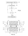
- FIG. 6 is an example of a method according to the invention.
- FIGS. 7A and 7B are examples of a gas purifying device to which the invention can be applied.
- FIGS. 8A and 8B are examples of shapes of oxygen traps.
- FIG. 1 schematically illustrates a bar 2 or sample able to be used in the invention.
- YSZ yttrium-stabilized zirconium
- getter material it is possible, as getter material, to use any solid solution of ZrYO or ZrScO type, with or without double substitutions (of Y 2 O 3 or Sc 2 O 3 , either by CeO 2 or by AlO 3 ) but also all structures such as ThO 2 — and LaGaO 3 ⁇ similar to ZrO 2 ⁇ bases, with or without double substitutions (of Y 2 O 3 or Sc 2 O 3 , either by CeO 2 or by Al 2 O 3 ). Mention can also be made of 8(Y 2 O 3 )10 (Al 2 O 3 ) mixtures.
- a zirconium solution can be used such as Zr 1-x Y x O 2-x/2 or Zr 1-x Sc x O 2-x/2 with x between 0.03 and 0.11.
- a double substitution solid solution such as ZrO 2 (0.86)Y 2 O 3 (0.1)CeO 2 (0.04) or ZrO 2 (0.9)Y 2 O 3 (0.09)CeO 2 (0.01) can also be used.
- the inventors have been able to determine that the behaviour of a getter follows dynamics which appear to be exclusively or chiefly related to the re-oxidation process of materials and not to inertia of the gas as described in the work conducted under argon in particular by J. Foultier et al., Vacuum, 25, 1975, 307.
- a region 30 of non-reduced zirconium can be seen and a black zirconium region 40 (reduced). These two regions are delimited by a reduction front 32 that is assumed to be planar.
- V T (en m 3 ) be the volume of the sample and S its cross-section (in m 2 ).
- this sample can be incorporated in a circuit comprising a voltage source 4 , means 6 to measure a current circulating in the sample, the assembly being linked in series by electrical connections 3 , 5 .
- the sample 2 is provided with electrodes 7 , 9 . A potential difference or a voltage is therefore applied to the terminals of the sample. This voltage is denoted ⁇ E (in V).
- K 0 (in A/m 2 ) can be inferred therefrom; these values are also dependent on the morphology of the sample, in particular its active surface area, and it was also ascertained that K 0 is dependent on temperature range ( ⁇ 20° C.) and the range of applied potential ( ⁇ 0.5V).
- X 1 represents the number of oxygen atoms which can be exchanged with the external gas surrounding the getter.
- X 2 represents the oxygens involved in internal exchanges but their physicochemical nature is unknown, and C 2 is their concentration.
- ⁇ E ion is the non-measurable difference in ionic potential.
- I f (t) represents the charge transfer occurring within the bar or sample during polarisation
- I f,1 (t) is charge transfer related to re-oxidation of the bar
- I f,2 (t) represents oxygen exchanges within the bar.
- the operator (or automaton) has knowledge of I m (measured current) and ⁇ E (the potential applied to the terminals of the sample). These values can be stored in memory.
- X 1 amount of oxygen available for re-oxidation
- the front position is expressed by:
- equations (2a) and (3a) By analysis of equations (2a) and (3a), it is shown by combining equations (2c) and (3b) that for dl m /dt ⁇ 0 (the case dl m /dt ⁇ 0 corresponds solely to internal exchanges without reduction or regeneration) the front position of ⁇ can be written:
- L Regenerative represents the length that it is possible to regenerate (L Regenerative can be taken to be slightly shorter than the length of the bar to take into account electrode dimensions).
- the second and third parts of the 2 nd member (which are the terms in ⁇ 1/C1S2F and ⁇ E/K 0 ) of the above expression give the reduced length.
- ⁇ can have a value higher than L Regenerative on account of the pollution-related current Ip which can be determined by a current at
- pollution may evolve; to give consideration thereto it is possible, by merely interrupting the regeneration current, to measure or record I p for example at regular time intervals e.g. every 5 or 10 seconds.
- the parameters S and ⁇ ion eff K 0 , C 1 can be determined or estimated.
- the percentage of uncertainty established on each of the parameters allows dimensioning of reducible length.
- dl m /dt ⁇ 0 corresponds to internal exchanges within the sample which are very rapid.
- dl m /dt>0 corresponds to the case in which oxygen is released into the atmosphere outside the sample (this is a regeneration situation since oxygen is released from the sample).
- the current values can be transmitted to data processing means 16 .
- These means 16 comprise a computer for example or micro-computer or calculator or an electrical circuit or a programmable or programmed electronic circuit or a microprocessor programmed to store in memory and process current data e.g. data supplied by the means 6 , and data to implement a method according to the invention. In this manner the value ⁇ of the regeneration front can be estimated or calculated.
- a central unit 17 is programmed to apply a processing method of the invention.
- the values of dl m /dt can be estimated by numerical derivation (so-called ⁇ naive>> method), for example for a time interval imposed by the operator (e.g. 5 to 100 seconds).
- the means 17 apply another method e.g. fast-scan voltammetry or square-wave potential technique or low frequency complex impedance spectroscopy. These methods can be accompanied by a calibration step and the correlation which relates their results to Ip can be more or less complex.
- the means 17 can estimate or calculate the value ⁇ of the regeneration front.
- These means 17 can also allow a comparison between this value of ⁇ and a threshold value, and controlling of the switch 8 used to stop circulation of the regeneration current in the sample 2 .
- FIG. 3 illustrates different monitoring operations of the criterion I m (I m ⁇ I p )/(dl m /dt), with Ip close to 0.
- the initial resistances were measured at the terminals of a parallelepiped bar of dense 8YSZ material (8 mole % yttrium-stabilized zirconium (YSZ)).
- the measuring technique used was high frequency impedance.
- the operating temperatures were 900° C. and 850° C. These resistances exhibited strong variability depending on historical data of preceding regenerations.
- the criterion I m (I m ⁇ I p )/(dl m /dt) was measured during reductions under argon (Ar) and 3% hydrogenated Argon (ArH). During regeneration under ArH at 900° C., regeneration was stopped at a target value of 150 A.s.
- FIG. 4 illustrates monitoring of the current as a function of time for 3% hydrogenated argon gas at 850° C., under 5 V polarization (same case as in FIG. 3 ).
- FIG. 5 for a porous cylindrical sample at 850° C. under argon, illustrates monitoring of reducing current under 5 V and an example of Ip determination technique.
- FIG. 6 An example of a method which can be implemented according to the invention is schematically illustrated in FIG. 6 .
- a certain number of initial parameters can be measured or calculated e.g. ⁇ ion eff , K 0 , C 1 . It is possible to infer
- step S 3 From these measured values it is possible to estimate or calculate value ⁇ (step S 3 ).
- step S 4 As a function of the result of comparison between this value and a threshold value ⁇ s , it can be decided to stop or continue regeneration (step S 4 ). In the latter case measurements of I are continued (step S 2 ).
- Regeneration according to the invention can be carried out automatically after a certain time of use of the getter. Regeneration can be triggered by the means 17 programmed for this purpose e.g. on the basis of a clock signal.
- a potential application test is applied e.g. for a time of 5 to 10 seconds and current I m is measured; also, a current I E is estimated as a function of the applied potential and of estimated regenerated length (application of Ohm's law); if the estimated current I E is higher than the measured current I m , regeneration is triggered.
- FIGS. 7A and 7B illustrate 2 devices to which the invention can be applied; these devices are described in document FR 2230402.
- the device in FIG. 7A comprises an enclosure 102 , inlet means for the gas to be purified comprising a connector 104 controlled by a valve 106 and means to evacuate this gas from the enclosure comprising a connector 108 controlled by a valve 110 .
- a porous block 112 of getter material e.g. formed of a solid solution such as defined above.
- the gas entering via connector 104 can only be evacuated via connector 108 after it has passed through the porous block 112 .
- enclosure 102 and the block 112 both have a general cylindrical shape, the block being held in position in this enclosure via bottleneck regions 114 for example formed in the enclosure.
- the block 112 is inserted in an electric circuit comprising a generator of direct or rectified current 115 the terminals of which are electrically connected to opposite ends of the block, for example via metal conductors, 116 a, 116 b simply placed in contact with the solid electrolyte.
- a generator of direct or rectified current 115 the terminals of which are electrically connected to opposite ends of the block, for example via metal conductors, 116 a, 116 b simply placed in contact with the solid electrolyte.
- metal conductors, 116 a, 116 b simply placed in contact with the solid electrolyte.
- they are embedded in the ends of the block 112 , their securing having been achieved by co-sintering with the block during the formation thereof.
- An oven 116 surrounds the enclosure 102 , at least the part thereof in which the block 112 is positioned, this oven being able to bring the solid solution to the temperature at which it has notable ionic and electronic conductivities, for example in the order of 600° C. to 800° C., when the block is formed of the solid solution containing zirconium, yttrium and cerium oxides, in particular in the above-indicated proportions.
- the apparatus also comprises means, particularly comprising a connector 120 and valve 122 to emit an inert gas or hydrogen inside the enclosure and means to evacuate this gas which particularly comprise a connector 124 and valve 126 , these latter inlet and evacuation means preferably being arranged such that the input gas is caused to circulate in the opposite direction to the direction normally taken in a prior step by the gas to be purified.
- the apparatus thus prepared operates as follows.
- the solid solution of the block 112 is converted to its “reduced form”, in particular by passing an electric current through the block in a direction which results from the indication of the + and ⁇ polarities respectively associated with the conductors 116 a and 116 b.
- This step is performed by estimating the length of regeneration according to the present invention.
- valves 106 and 110 are closed whilst valves 122 and 126 are open and allow a gas to pass through the porous block such as nitrogen or a neutral gas but also hydrogen which entrains the oxygen released by the electrochemical reduction operation.
- a gas such as nitrogen or a neutral gas but also hydrogen which entrains the oxygen released by the electrochemical reduction operation.
- This reduction operation can be accompanied by blackening of the porous mass.
- the oxygen trap is then able to function in particular under the following conditions.
- Valves 122 and 126 are closed and valves 106 and 110 are open, the latter allowing the gas to be purified to enter the enclosure via the connector 104 , to pass in contact with the porous block 112 and to be evacuated via connector 110 .
- the traces of oxygen contained in the gas to be purified are then energetically fixed by the solid solution of the block 112 .
- Oxygen adsorption is rapid irrespective of the degree of oxidation of the solid solution, and in particular the rate of oxygen adsorption is not substantially affected by this degree of oxidation for as long as it remains lower than its value in natural solid solutions.
- the solid solution is regenerated by converting it to its reduced form under the conditions of the present invention indicated above.
- the trap just described is therefore capable of operating discontinuously.
- FIG. 7B illustrates a variant of this oxygen trap, this variant being able to operate continuously.
- the different parts of the apparatus in FIG. 7B have been given the same reference numbers as the corresponding parts of the apparatus in FIG. 7A , together with an index. Only different parts have been given new reference numbers.
- the apparatus in FIG. 7B essentially differs from the one in FIG. 5A in that the enclosure 102 a is divided into two separate compartments 128 and 130 , in that the block 112 a comprises two parts 131 a, 131 b contained in compartments 128 , 130 respectively, and in that a gas-tight separation is formed between the two compartments and between the above-said parts 131 a, 131 b, without the gases in contact with one of said parts being able to diffuse in the gaseous state into the other through the bulk of the block.
- the parts 131 a, 131 b of the block 112 a are porous and separated by a compact or solid central portion 131 c, the separation between the two compartments 128 , 130 being obtained via a partition 132 in which a central opening is provided allowing passage into the block 112 a, in the central portion thereof, a seal for example in enamel providing imperviousness between the central portion 131 c and the edges of the opening in the partition 132 .
- the block 112 a is inserted in an electric circuit comprising a current generator 115 a having its positive terminal connected to end 136 and negative terminal connected to end 138 of the block 112 a, in compartments 128 and 130 respectively.
- the entry of the gas to be purified is through the connector 104 a into compartment 130 , the purified gas being evacuated through connector 108 a, whilst an inert gas is caused to enter compartment 128 via connector 120 a and evacuated outside compartment 128 via connector 122 a.
- the traces of oxygen contained in the gas entering compartment 130 are therefore retained in the corresponding part of block 112 a, in the form of ions which migrate in the bulk of the porous block in particular in the general direction indicated by arrow 140 when the generator is powered, these oxygen ions being converted to gaseous oxygen atoms in the vicinity of end 136 of the block 112 a in contact with the conductor 116 a to which the electrons are transferred.
- a neutral or reducing gas such as purge hydrogen caused to enter compartment 128 via connector 120 a, entrains the gaseous oxygen or formed vapour towards the evacuation connector 122 a.
- the invention therefore particularly allows the applying of continuous mode purification.
- the invention has been described with a solid cylindrical bar 2 , but other shapes of samples can be used.
- the material of the trap 2 is of elongate shape e.g. cylindrical or parallelepiped.
- it may be in the form of a pellet ( FIG. 8A ) or hollow tube, with circular, rectangular or square cross-section (case in FIG. 8B ).
- the shape of the electrodes applied to the sample (such as electrodes 7 , 9 in FIG. 2 ) is adapted to the shape of the sample.
- the sample may be composed of a material which may be porous or dense.
- the gas to be purified with the getter may be hydrogen or any other neutral gas e.g. of the type used in the field of microelectronics such as argon, helium or nitrogen.
Landscapes
- Chemical & Material Sciences (AREA)
- Chemical Kinetics & Catalysis (AREA)
- Analytical Chemistry (AREA)
- Engineering & Computer Science (AREA)
- Organic Chemistry (AREA)
- Inorganic Chemistry (AREA)
- Oil, Petroleum & Natural Gas (AREA)
- Health & Medical Sciences (AREA)
- General Chemical & Material Sciences (AREA)
- Metallurgy (AREA)
- Materials Engineering (AREA)
- Electrochemistry (AREA)
- Sustainable Development (AREA)
- Toxicology (AREA)
- Biomedical Technology (AREA)
- Life Sciences & Earth Sciences (AREA)
- Environmental & Geological Engineering (AREA)
- Physics & Mathematics (AREA)
- Electromagnetism (AREA)
- General Health & Medical Sciences (AREA)
- Automation & Control Theory (AREA)
- Investigating Or Analyzing Non-Biological Materials By The Use Of Chemical Means (AREA)
- Inorganic Compounds Of Heavy Metals (AREA)
- Solid-Sorbent Or Filter-Aiding Compositions (AREA)
- Investigating Or Analyzing Materials By The Use Of Electric Means (AREA)
- Investigating Or Analyzing Materials By The Use Of Fluid Adsorption Or Reactions (AREA)
Abstract
Description
- The invention concerns the field of oxygen pumps or traps also known as <<getters>>.
- Oxygen traps are a reliable technical solution to remove every trace of oxygenated pollutants in a gas. For example, the use at high temperature (between 600° C. and 900° C.) of a regenerative oxygen trap was proposed as early as 1973 in document U.S. Pat. No. 3,963,597. The device proposed in this document is based on the difference in thermodynamic potential between partly reduced zirconium oxide and pollutants (in the order of potentials from the highest to the lowest: CO2>H2O>CO>NO). A good candidate for this purpose is reduced 8 mole % yttrium-stabilized zirconium. It exhibits very good stability under a reducing gas, under hydrogen in particular, and excellent forming properties.
- In particular this document describes a variant for continuous operation. However, the variation in existing volume during reduction followed by re-oxidation does not allow reliable gas-tightness for continuous operation mode. The reduction current is determined from an estimate of the pollution level of the gas entering the cell.
- The document by J. Foultier et al., Vacuum, 25, 1975, 307 proposes a solid solution of ZrO2(0.86) Y2O3(0.1)CeO2(0.04) or ZrO2(0.9)Y2O3(0.09)CeO2(0.01). It is shown therein that 100 grams of said trap is able to trap 1 NI of dioxygen. According to the article <<Actualités chimie>> N° 1534-3, July 1974, pages 24-28, after 6 months' use and more than 50 regeneration cycles, the sample shows no degradation. Finally, under argon the performance of pollutant removal is largely dependent on the flow of gas passing through the trap. It has been demonstrated via numerical simulations and by the study of dimensionless numbers (Pe, Sc, Sh), that it is dependent on the type of gas (dihydrogen or argon). In this type of technique, after the oxygen has been trapped by the constituent material of the trap followed by oxygen saturation of this material, the problem arises of the regeneration thereof.
- This is obtained by circulating a current as described in the aforementioned documents.
- Although very simple, this technique has never been automated. According to known regeneration techniques, the type of gas passing through the cell is changed and the level of re-oxidation of the trap is measured using high frequency impedance. Finally, the reversibility of this regeneration under highly reducing gas (hydrogen) has never been clearly demonstrated.
- The needs of this type of <<getter>> device are increasing together with hydrogen applications. Pure hydrogen is chiefly recommended for analytical chemistry applications (GPC). The packaging of hydrogen for on-hydride storage must take into account the constraints laid down by the hydride container with regard to tolerance of the presence of oxygen (≦10 ppm d′O2).
- It is therefore important to propose a reliable, robust solution to guarantee the high purity of a gas such as hydrogen. Finally for use of hydrogen in fuel cells, owing to the diversity of possible hydrogen sources, it is similarly of importance to obtain guaranteed quality in terms of purity, free of oxygenated pollutants e.g. carbon monoxide (<60 ppm de CO).
- The problem therefore arises of finding a novel method for regenerating the constituent material of an oxygen trap.
- In addition, in known regeneration methods, the halting of regeneration is arbitrary without any well-established criterion.
- The problem therefore also arises of finding a method to regenerate the constituent material of an oxygen trap which allows the determination of an easy criterion for halting regeneration.
- Said method to regenerate the constituent material of an oxygen trap can preferably be automated, allowing regeneration to be stopped on the basis of an objective criterion and/or an easily determined or calculated parameter.
- The invention sets out to solve these problems.
- First it concerns a method to regenerate an oxygen trap, comprising at least the following steps:
- a) circulating a current in the trap material to reduce this material;
- b) measuring the value Im of said current and estimating its derivative dlm/dt in relation to time;
- c) estimating the length (δ) of material reduced by said current, as a function of the value of said current (Im) and of its derivative (dlm/dt),
- d) stopping the circulation of the current when the length of reduced material is at least equal to a threshold value (δs).
- The length of reduced material may be a function of the ratio Im 2/(dlm/dt) between the square of measured current and its derivative.
- It is also possible to measure or estimate the contribution to the measured current made by electrochemical reductions of pollutants in the environment of the trap.
- It is then possible to estimate the length (δ) of reduced material as a function of the value of measured current (Im), of its derivative (dlm/dt) and of the contribution to the measured current made by electrochemical reductions of pollutants.
- For this purpose, it is possible to measure or record the value of the residual current Ip=I(dl/dt=0) for a zero or near-zero derivative of the current, for example at zero potential difference or by interrupting current circulation; it is then possible to estimate the length of reduced material as a function of the value of the current (Im), of its derivative (dlm/dt) and value of the current (I(dl/dt=0)) for a zero or near-zero derivative thereof. Interruption of the current and measurement of the value of the current (Ip), in particular for a zero or near-zero derivative thereof, can be performed at regular time intervals e.g. between 5 s and 100 s.
- As a variant, the instant (maximum) value of the current can be estimated when it is interrupted or at the time of interruption of the regeneration; this value can then be ten to one hundred times higher than Ip=I(dl/dt=0) and this method can therefore be accompanied by a calibration (of Ip∝IinstΔE=0) (this calibration depending on the frequency of acquisition).
- Finally, other methods exist which can be used to determine the influence on Im, of the concentration of this pollution surrounding the getter or the surface thereof, or the contribution to the measured current Im made by electrochemical reductions of pollutants in the environment: fast-scan voltammetry or square-wave potential technique or low frequency complex impedance spectroscopy. These methods can be accompanied by a calibration step; results are related to Ip by correlation.
- The estimated length of material can be a function of the ratio Im(Im−Ip)/(dlm/dt) between first the product of the current and of the current, minus, or corrected for, the current related to oxygen pollution of the gas circulating around the trap, and secondly the derivative of the current.
- Regeneration can take place for example at a temperature between 600° C. and 900° C.
- The invention also concerns a device to regenerate an oxygen trap, comprising at least:
- a) means to circulate a current in the trap material for reduction thereof;
- b) means to measure the value of said current and to calculate its derivative;
- c) means to estimate the length of reduced material as a function of the value of said current and of its derivative;
- d) means to stop circulation of the current when the length of reduced material is equal to a threshold value.
- Means can be provided to measure or estimate the contribution to the measured current made by electrochemical reductions of pollutants in the environment of the trap.
- Means can allow estimation of the length (δ) of reduced material as a function of the value of the measured current (Im), of its derivative (dl/dt) and of the contribution, to the measured current, made by electrochemical reductions of pollutants.
- Said device may further comprise means to measure or record the value of the residual current Ip=I(dl/dt=0), for a zero or near-zero derivative of the current e.g. at zero potential difference or by interrupting circulation of the current; means then allowing estimation of the length of reduced material as a function of the value of the current (Im), of its derivative (dlm/dt) and of the value of the current (I(dl/dt=0)) for a zero or near-zero derivative thereof. Preferably current interruption means, in particular for a zero or near-zero derivative of the current, allow measurement of the value of the current (Ip) at regular time intervals e.g. between 5 s and 100 s.
- As a variant, there are means allowing interruption of regeneration and means allowing estimation of the instant (or maximum) value of the current at the time of this interruption; this value may then be ten to one hundred times higher than Ip=I(dl/dt=0); means can therefore be provided for calibration (of Ip∝IinstΔE=0) (calibration depending on acquisition frequency).
- Finally, means can be provided to implement other methods which can be applied to determine the influence on Im of the concentration of the pollution surrounding the getter or the surface thereof, or the contribution, to the measured current Im, made by electrochemical reductions of environment pollutants: fast-scan voltammetry or square-wave potential technique, or low frequency complex impedance spectroscopy. Means can be provided to allow calibration and/or correlation to relate results to Ip.
- Means can be provided or programmed to:
- interrupt circulation of the current and to measure the value of the current (Ip=I(dl/dt=0)) for a zero or near-zero derivative thereof and/or to measure the maximum value of the current at the time of interruption, or any other conventional electrochemical method allowing determination of the concentration of pollutants and to infer Ip therefrom;
- and/or to trigger means to circulate a current in the trap material to reduce this material.
- In a method or device of the invention the trap material is a solid solution for example, usually used as solid electrolyte in a high temperature solid oxide fuel cell.
- The <<getter>> material is any solid solution for example of ZrYO or ZrScO type, with or without double substitutions (of Y2O3 or Sc2O3, either by CeO2 or by Al2O3); as a variant, this may a structure such as ThO2 − and LaGaO3 − similar to ZrO2 − bases with or without double substitutions (of Y2O3 or Sc2O3, either by CeO2 or by Al2O3). Mention can also be made of 8(Y2O3)10(Al2O3) mixtures.
- As an example, a zirconium solution can be used such as Zr1-xYxO2-x/2 or Zr1-xScxo2-x/2 with x between 0.03 and 0.11. A solid solution with double substitution can also be used such as ZrO2(0.86)Y2O3(0.1)CeO2(0.04) or ZrO2(0.9)Y2O3(0.09)CeO2(0.01).
- The trap material may be of elongate shape e.g. cylindrical or parallelepiped, optionally hollow, or in the shape of a pellet of hollow tube e.g. with circular or rectangular or square cross-section. It may be dense or porous.
- The invention allows easy automation of control over regeneration of an oxygen trap.
-
FIG. 1 illustrates an oxygen trap. -
FIG. 2 illustrates a device to regenerate an oxygen trap implementing the invention. -
FIG. 3 illustrates monitoring of Im(Im−Ip)/(dlm/dt) as a function of time. -
FIG. 4 is an example of the monitoring of current Im as a function of time according to a method of the invention. -
FIG. 5 is an example of the monitoring of current Im as a function of time according to a method of the invention, with determination of I. -
FIG. 6 is an example of a method according to the invention. -
FIGS. 7A and 7B are examples of a gas purifying device to which the invention can be applied. -
FIGS. 8A and 8B are examples of shapes of oxygen traps. -
FIG. 1 schematically illustrates a bar 2 or sample able to be used in the invention. - For example, it is a sample of 8 mole % yttrium-stabilized zirconium (YSZ), stable under a reducing atmosphere.
- Trap performance was not proven on this solid solution. The endurance thereof was previously tested by performing about ten reduction and re-oxidation cycles. It was also shown that this is possible under a hydrogen atmosphere.
- As a variant it is possible, as getter material, to use any solid solution of ZrYO or ZrScO type, with or without double substitutions (of Y2O3 or Sc2O3, either by CeO2 or by AlO3) but also all structures such as ThO2— and LaGaO3 − similar to ZrO2 − bases, with or without double substitutions (of Y2O3 or Sc2O3, either by CeO2 or by Al2O3). Mention can also be made of 8(Y2O3)10 (Al2O3) mixtures.
- As an example, a zirconium solution can be used such as Zr1-xYxO2-x/2 or Zr1-xScxO2-x/2 with x between 0.03 and 0.11. A double substitution solid solution such as ZrO2(0.86)Y2O3(0.1)CeO2(0.04) or ZrO2(0.9)Y2O3(0.09)CeO2(0.01) can also be used.
- The inventors have been able to determine that the behaviour of a getter follows dynamics which appear to be exclusively or chiefly related to the re-oxidation process of materials and not to inertia of the gas as described in the work conducted under argon in particular by J. Foultier et al., Vacuum, 25, 1975, 307.
- An oxygen getter operating under a hydrogen atmosphere is able to capture a large amount of pollutant (in particular during pollution peaks) within a very short time, due to the very high diffusivity of pollutants in hydrogen. CFD code numerical simulation and the study of dimensionless numbers (Pe, Sc, Sh) prove that the purge rate has little influence on trap performance, since hydrogen has very good thermal diffusivity and a very high binary diffusion coefficient.
- Regeneration tests were conducted by the inventors, evidencing an unusual behaviour of ceramic that has never been reported in the literature.
- Modeling thereof is proposed below that is easy and robust and allows an explanation of this behaviour.
- With this modeling it is possible to control the state of reduction by measuring the current as a function of time.
- In the partly oxidized getter sample (the material of which is ytrrium-stabilized zirconium as indicated above) illustrated in
FIG. 1 , aregion 30 of non-reduced zirconium can be seen and a black zirconium region 40 (reduced). These two regions are delimited by areduction front 32 that is assumed to be planar. - Let VT (en m3) be the volume of the sample and S its cross-section (in m2).
- As illustrated in
FIG. 2 , this sample can be incorporated in a circuit comprising a voltage source 4, means 6 to measure a current circulating in the sample, the assembly being linked in series byelectrical connections - Through previous electrochemical characterization (e.g. by high frequency complex impedance spectroscopy) it is possible to determine an effective ionic conductivity σion eff, which is dependent on the morphology (porosity) of the sample.
- An exchange current K0 (in A/m2) can be inferred therefrom; these values are also dependent on the morphology of the sample, in particular its active surface area, and it was also ascertained that K0 is dependent on temperature range (±20° C.) and the range of applied potential (±0.5V).
- Finally, on the basis of the type of solid solution and the porosity thereof it is possible to estimate the concentration C1 (in mol/m3) of reducible oxygen contained in the material. This concentration is given by:
-
- with i: 1 or 2
- It relates to the number of moles of exchangeable oxygen in the regenerative length. X1 represents the number of oxygen atoms which can be exchanged with the external gas surrounding the getter. X2 represents the oxygens involved in internal exchanges but their physicochemical nature is unknown, and C2 is their concentration.
- Let Ohm's law expressed from this analysis be:
-
- where ΔEion is the non-measurable difference in ionic potential.
- The following linearized electrochemical overvoltage law is proposed for X2≧0 and 0≦X1≦C1VT (these two inequalities are in fact always verified since they correspond to the mass balance in the ceramic):
-
- In this equality If(t) represents the charge transfer occurring within the bar or sample during polarisation, If,1(t) is charge transfer related to re-oxidation of the bar, If,2(t) represents oxygen exchanges within the bar.
- Under strong pollution it was found that it is possible to observe a current (Ip) related to electrochemical reduction of the pollutants. It is not possible to relate this current to an overvoltage law but nevertheless an expression of current density representative thereof is used:
-
I T =I f +I p (2b) - For X2=0, the expression (2a) is reduced to:
-
- The mass and charge balance is then expressed by the evolution rule of X1 and X2; for X2≧0:
-
- And for 0≦X1≦C1VT
-
- with F being Faraday's constant (C/mol).
- The operator (or automaton) has knowledge of Im (measured current) and ΔE (the potential applied to the terminals of the sample). These values can be stored in memory.
- If it is written:
-
I m=(I f +I p)S (4a) - Assuming that the time constant of the pollution-related current is lower than the constant which corresponds to internal regeneration of the ceramic:
-
- To determine the level of re-oxidation, it is sought to know X1 (amount of oxygen available for re-oxidation).
- The front position is expressed by:
-
(V T −X 1 /C 1)/S - By analysis of equations (2a) and (3a), it is shown by combining equations (2c) and (3b) that for dlm/dt≧0 (the case dlm/dt<0 corresponds solely to internal exchanges without reduction or regeneration) the front position of δ can be written:
-
- LRegenerative represents the length that it is possible to regenerate (LRegenerative can be taken to be slightly shorter than the length of the bar to take into account electrode dimensions). The second and third parts of the 2nd member (which are the terms in −1/C1S2F and ΔE/K0) of the above expression give the reduced length.
- Therefore δ can have a value higher than LRegenerative on account of the pollution-related current Ip which can be determined by a current at
-
- and/or by measuring the maximum value of the current at the time of interruption, or by any other electrochemical method allowing determination of pollutant concentration and to infer Ip therefrom. This latter term is the contribution to the signal made by exchanges related to electrochemical reduction of pollutants in the environment.
- By means of electrochemical measurements e.g. voltamperometry or complex electrochemical impedance, it is possible to determine
-
- but with variable accuracy depending on operating temperature (±10% at 900° C. and ±20% at 800° C.). Through geometric measurement and coulometry, at the time of total regeneration, and irrespective of temperature, it is possible to determine
-
- to within ±5%.
- With this fine-tuned knowledge of the system under polarization, it is easy to stop regeneration when δ reaches a set value δs: for as long as δ calculated using the above formula or a similar formula remains below this threshold δs, regeneration is continued. It is halted when δ, estimated or calculated using the above formula or similar formula, becomes equal to or higher than this threshold value δs.
- In addition pollution may evolve; to give consideration thereto it is possible, by merely interrupting the regeneration current, to measure or record Ip for example at regular time intervals e.g. every 5 or 10 seconds.
- As indicated above, the parameters S and σion eff K0, C1 can be determined or estimated. In addition, the percentage of uncertainty established on each of the parameters allows dimensioning of reducible length.
- The above formula shows that the front position is dependent on I2 m/(dlm/dt); if the atmosphere is not pure, this position is dependent on Im(Im−Ip)/(dlm/dt).
- dlm/dt<0 corresponds to internal exchanges within the sample which are very rapid.
- The case dlm/dt=0 corresponds to the case in which the sample exchanges oxygen with the outside of the sample.
- dlm/dt>0 corresponds to the case in which oxygen is released into the atmosphere outside the sample (this is a regeneration situation since oxygen is released from the sample).
- Current measurements can be performed using an
ammeter 6 arranged in series with the bar or sample 2. - The current values can be transmitted to data processing means 16.
- These means 16 comprise a computer for example or micro-computer or calculator or an electrical circuit or a programmable or programmed electronic circuit or a microprocessor programmed to store in memory and process current data e.g. data supplied by the
means 6, and data to implement a method according to the invention. In this manner the value δ of the regeneration front can be estimated or calculated. - For example, a
central unit 17 is programmed to apply a processing method of the invention. In particular the values of current I for dl/dt=0 or the maximum value (IinstΔE=0) of the current at the time of interruption or regeneration can be measured or estimated. The values of dlm/dt can be estimated by numerical derivation (so-called <<naive>> method), for example for a time interval imposed by the operator (e.g. 5 to 100 seconds). As a variant, themeans 17 apply another method e.g. fast-scan voltammetry or square-wave potential technique or low frequency complex impedance spectroscopy. These methods can be accompanied by a calibration step and the correlation which relates their results to Ip can be more or less complex. - In addition the values of
-
- may be previously measured and also stored in memory in the
means 17. - On the basis of these data, the
means 17 can estimate or calculate the value δ of the regeneration front. - These means 17 can also allow a comparison between this value of δ and a threshold value, and controlling of the
switch 8 used to stop circulation of the regeneration current in the sample 2. - On the monitor or visualizing means 19 it is possible for example to display the changes in measured current as a function of time and/or changes in δ.
-
FIG. 3 illustrates different monitoring operations of the criterion Im(Im−Ip)/(dlm/dt), with Ip close to 0. The initial resistances were measured at the terminals of a parallelepiped bar of dense 8YSZ material (8 mole % yttrium-stabilized zirconium (YSZ)). The measuring technique used was high frequency impedance. The operating temperatures were 900° C. and 850° C. These resistances exhibited strong variability depending on historical data of preceding regenerations. The criterion Im(Im−Ip)/(dlm/dt) was measured during reductions under argon (Ar) and 3% hydrogenated Argon (ArH). During regeneration under ArH at 900° C., regeneration was stopped at a target value of 150 A.s. -
FIG. 4 illustrates monitoring of the current as a function of time for 3% hydrogenated argon gas at 850° C., under 5 V polarization (same case as inFIG. 3 ). -
FIG. 5 , for a porous cylindrical sample at 850° C. under argon, illustrates monitoring of reducing current under 5 V and an example of Ip determination technique. After a reducing time of 200 seconds of a sample already partly reduced (which is the most complex case), the regeneration process was interrupted and the short circuit current was measured (zero potential): this is the current interruption technique. In the case in hand the measurement gave Ip=I(dl/dt=0)=0.6 mA. - An example of a method which can be implemented according to the invention is schematically illustrated in
FIG. 6 . - At a first step (S1), a certain number of initial parameters can be measured or calculated e.g. σion eff, K0, C1. It is possible to infer
-
- therefrom.
- Measurements of I are then performed (step 2) in particular for Ip=I(dl/dt=0) or for Ip∝IinstΔE=0.
- From these measured values it is possible to estimate or calculate value δ (step S3).
- As a function of the result of comparison between this value and a threshold value δs, it can be decided to stop or continue regeneration (step S4). In the latter case measurements of I are continued (step S2).
- Regeneration according to the invention can be carried out automatically after a certain time of use of the getter. Regeneration can be triggered by the
means 17 programmed for this purpose e.g. on the basis of a clock signal. As a variant, a potential application test is applied e.g. for a time of 5 to 10 seconds and current Im is measured; also, a current IE is estimated as a function of the applied potential and of estimated regenerated length (application of Ohm's law); if the estimated current IE is higher than the measured current Im, regeneration is triggered. -
FIGS. 7A and 7B illustrate 2 devices to which the invention can be applied; these devices are described in document FR 2230402. - The device in
FIG. 7A comprises anenclosure 102, inlet means for the gas to be purified comprising aconnector 104 controlled by a valve 106 and means to evacuate this gas from the enclosure comprising aconnector 108 controlled by avalve 110. Inside the enclosure there is aporous block 112 of getter material e.g. formed of a solid solution such as defined above. The gas entering viaconnector 104 can only be evacuated viaconnector 108 after it has passed through theporous block 112. - Here the
enclosure 102 and theblock 112 both have a general cylindrical shape, the block being held in position in this enclosure viabottleneck regions 114 for example formed in the enclosure. - The
block 112 is inserted in an electric circuit comprising a generator of direct or rectified current 115 the terminals of which are electrically connected to opposite ends of the block, for example via metal conductors, 116 a, 116 b simply placed in contact with the solid electrolyte. In the experimental enclosure inFIG. 7A they are embedded in the ends of theblock 112, their securing having been achieved by co-sintering with the block during the formation thereof. - An
oven 116 surrounds theenclosure 102, at least the part thereof in which theblock 112 is positioned, this oven being able to bring the solid solution to the temperature at which it has notable ionic and electronic conductivities, for example in the order of 600° C. to 800° C., when the block is formed of the solid solution containing zirconium, yttrium and cerium oxides, in particular in the above-indicated proportions. - The apparatus also comprises means, particularly comprising a
connector 120 andvalve 122 to emit an inert gas or hydrogen inside the enclosure and means to evacuate this gas which particularly comprise aconnector 124 and valve 126, these latter inlet and evacuation means preferably being arranged such that the input gas is caused to circulate in the opposite direction to the direction normally taken in a prior step by the gas to be purified. - The apparatus thus prepared operates as follows.
- At a first stage the solid solution of the
block 112 is converted to its “reduced form”, in particular by passing an electric current through the block in a direction which results from the indication of the + and − polarities respectively associated with theconductors - During this operation, the
valves 106 and 110 are closed whilstvalves 122 and 126 are open and allow a gas to pass through the porous block such as nitrogen or a neutral gas but also hydrogen which entrains the oxygen released by the electrochemical reduction operation. - This reduction operation can be accompanied by blackening of the porous mass.
- On completion of this operation, the supply to the electric circuit is interrupted.
- The oxygen trap is then able to function in particular under the following conditions.
-
Valves 122 and 126 are closed andvalves 106 and 110 are open, the latter allowing the gas to be purified to enter the enclosure via theconnector 104, to pass in contact with theporous block 112 and to be evacuated viaconnector 110. - The traces of oxygen contained in the gas to be purified are then energetically fixed by the solid solution of the
block 112. - According to document FR 2230402, observation of colouring of the block allows the moment to be estimated on and after which its adsorption capacity is exhausted, since it only returns to white when it has been fully re-oxidized. However this is not achievable when the process is in progress on account of temperature; it is this problem that is solved by the present invention.
- By monitoring the current Im as proposed herein, it is possible to observe the level of reduction or re-oxidation as shown in
FIG. 5 for example. - Oxygen adsorption is rapid irrespective of the degree of oxidation of the solid solution, and in particular the rate of oxygen adsorption is not substantially affected by this degree of oxidation for as long as it remains lower than its value in natural solid solutions.
- When this maximum degree of oxidation is reached, the solid solution is regenerated by converting it to its reduced form under the conditions of the present invention indicated above.
- The trap just described is therefore capable of operating discontinuously.
-
FIG. 7B illustrates a variant of this oxygen trap, this variant being able to operate continuously. The different parts of the apparatus inFIG. 7B have been given the same reference numbers as the corresponding parts of the apparatus inFIG. 7A , together with an index. Only different parts have been given new reference numbers. - The apparatus in
FIG. 7B essentially differs from the one inFIG. 5A in that theenclosure 102 a is divided into twoseparate compartments block 112 a comprises twoparts compartments parts - Advantageously, the
parts block 112 a are porous and separated by a compact or solidcentral portion 131 c, the separation between the twocompartments block 112 a, in the central portion thereof, a seal for example in enamel providing imperviousness between thecentral portion 131 c and the edges of the opening in the partition 132. - The
block 112 a is inserted in an electric circuit comprising acurrent generator 115 a having its positive terminal connected to end 136 and negative terminal connected to end 138 of theblock 112 a, incompartments - The entry of the gas to be purified is through the
connector 104 a intocompartment 130, the purified gas being evacuated throughconnector 108 a, whilst an inert gas is caused to entercompartment 128 viaconnector 120 a and evacuated outsidecompartment 128 viaconnector 122 a. - The traces of oxygen contained in the
gas entering compartment 130 are therefore retained in the corresponding part ofblock 112 a, in the form of ions which migrate in the bulk of the porous block in particular in the general direction indicated byarrow 140 when the generator is powered, these oxygen ions being converted to gaseous oxygen atoms in the vicinity ofend 136 of theblock 112 a in contact with theconductor 116 a to which the electrons are transferred. - A neutral or reducing gas such as purge hydrogen, caused to enter
compartment 128 viaconnector 120 a, entrains the gaseous oxygen or formed vapour towards theevacuation connector 122 a. - The invention therefore particularly allows the applying of continuous mode purification.
- It also, at any time, provides an indication of the re-oxidation level and hence allows best control over the system whether functioning in discontinuous or continuous mode.
- The invention has been described with a solid cylindrical bar 2, but other shapes of samples can be used.
- More generally, the material of the trap 2 is of elongate shape e.g. cylindrical or parallelepiped.
- As a variant, it may be in the form of a pellet (
FIG. 8A ) or hollow tube, with circular, rectangular or square cross-section (case inFIG. 8B ). The shape of the electrodes applied to the sample (such as electrodes 7, 9 inFIG. 2 ) is adapted to the shape of the sample. - Irrespective of shape, the sample may be composed of a material which may be porous or dense.
- The gas to be purified with the getter may be hydrogen or any other neutral gas e.g. of the type used in the field of microelectronics such as argon, helium or nitrogen.
- Examples of application of the invention are the following:
-
- purification of pollutants such as CO2, H2O, CO and NO in a neutral carrier gas or hydrogen;
- purification of He or H2 for analysis by gas phase chromatography (GPC);
- purification of H2 for on-hydride hydrogen storage;
- purification of H2 for use in fuel cells;
- purification of H2 for microelectronic processes;
- purification of neutral gases such as argon or nitrogen for any industrial use.
Claims (20)
Applications Claiming Priority (2)
| Application Number | Priority Date | Filing Date | Title |
|---|---|---|---|
| FR1463105A FR3030310B1 (en) | 2014-12-22 | 2014-12-22 | PROCESS FOR REGENERATING OXYGEN TRAP |
| FR1463105 | 2014-12-22 |
Publications (2)
| Publication Number | Publication Date |
|---|---|
| US20160177458A1 true US20160177458A1 (en) | 2016-06-23 |
| US10428433B2 US10428433B2 (en) | 2019-10-01 |
Family
ID=52589669
Family Applications (1)
| Application Number | Title | Priority Date | Filing Date |
|---|---|---|---|
| US14/976,288 Active 2036-10-06 US10428433B2 (en) | 2014-12-22 | 2015-12-21 | Method to regenerate oxygen traps |
Country Status (5)
| Country | Link |
|---|---|
| US (1) | US10428433B2 (en) |
| EP (1) | EP3037151B1 (en) |
| JP (1) | JP6688604B2 (en) |
| CA (1) | CA2915872C (en) |
| FR (1) | FR3030310B1 (en) |
Cited By (1)
| Publication number | Priority date | Publication date | Assignee | Title |
|---|---|---|---|---|
| US20200376429A1 (en) * | 2017-11-24 | 2020-12-03 | Universite Grenoble Alpes | Method for purifying a carrier gas |
Family Cites Families (5)
| Publication number | Priority date | Publication date | Assignee | Title |
|---|---|---|---|---|
| FR2230402B1 (en) * | 1973-03-30 | 1975-10-31 | Anvar | |
| JPH07172803A (en) * | 1992-04-16 | 1995-07-11 | Osaka Gas Co Ltd | Method for recovering gaseous oxygen and device therefor |
| US5334237A (en) * | 1993-02-26 | 1994-08-02 | Saes Pure Gas, Inc. | Method and apparatus for predicting end-of-life of a consumable in a fluid purification system |
| FR2720080B1 (en) * | 1994-05-19 | 1997-03-21 | Air Liquide | Composite structure comprising a solid electrolyte and at least one volume electrode. |
| FR2770149B1 (en) | 1997-10-29 | 1999-12-17 | Air Liquide | PROCESS FOR SEPARATING OXYGEN FROM A GAS MIXTURE CONTAINING SAME AND DEVICE FOR CARRYING OUT SAID METHOD |
-
2014
- 2014-12-22 FR FR1463105A patent/FR3030310B1/en not_active Expired - Fee Related
-
2015
- 2015-12-21 EP EP15201746.3A patent/EP3037151B1/en active Active
- 2015-12-21 CA CA2915872A patent/CA2915872C/en active Active
- 2015-12-21 US US14/976,288 patent/US10428433B2/en active Active
- 2015-12-22 JP JP2015249718A patent/JP6688604B2/en active Active
Cited By (2)
| Publication number | Priority date | Publication date | Assignee | Title |
|---|---|---|---|---|
| US20200376429A1 (en) * | 2017-11-24 | 2020-12-03 | Universite Grenoble Alpes | Method for purifying a carrier gas |
| US11717789B2 (en) * | 2017-11-24 | 2023-08-08 | Universite Grenoble Alpes | Method for purifying a carrier gas |
Also Published As
| Publication number | Publication date |
|---|---|
| CA2915872A1 (en) | 2016-06-22 |
| FR3030310B1 (en) | 2019-08-16 |
| EP3037151A1 (en) | 2016-06-29 |
| JP6688604B2 (en) | 2020-04-28 |
| FR3030310A1 (en) | 2016-06-24 |
| JP2016117061A (en) | 2016-06-30 |
| US10428433B2 (en) | 2019-10-01 |
| EP3037151B1 (en) | 2017-04-26 |
| CA2915872C (en) | 2023-01-03 |
Similar Documents
| Publication | Publication Date | Title |
|---|---|---|
| Ahn et al. | Quaternary phase relations near YBa2Cu3O6+ x at 850° C in reduced oxygen pressures | |
| Bucher et al. | Stability of the SOFC cathode material (Ba, Sr)(Co, Fe) O3− δ in CO2-containing atmospheres | |
| US9028671B2 (en) | Hydrogen sensing apparatus and method | |
| US10428433B2 (en) | Method to regenerate oxygen traps | |
| Darvish et al. | Thermodynamic stability mapping and electrochemical study of La1-xSrxCo0. 2Fe0. 8O3±δ (x= 0.2–0.4) as a cathode of solid oxide fuel cells in the presence of SO2 | |
| US4786395A (en) | Oxygen analyzer | |
| JPH0130102B2 (en) | ||
| JP2006513403A5 (en) | ||
| Wang et al. | A novel carbon dioxide gas sensor based on solid bielectrolyte | |
| RU2483300C1 (en) | Solid electrolyte sensor for amperometric measurement of gas mixture moisture | |
| Gur et al. | Ionic conductivity of 8mol.% Sc2O3 ZrO2 measured by use of both AC and DC techniques | |
| Niedrig et al. | High-Temperature p O2 Stability of Metal Oxides Determined by Amperometric Oxygen Titration | |
| Zhang et al. | Reference electrode of simple galvanic cells for developing sodium sensors for use in molten aluminum | |
| Porat et al. | Double‐Solid Electrochemical Cell for Controlling Oxygen Concentration in Oxides | |
| Salzano et al. | Ionic Range of ThO2‐15 w/o Y 2 O 3 at High Oxygen Activities | |
| JPH04320956A (en) | Connection-type gas sensor consisting of beta alumina and zirconia solid electrolyte | |
| RU63534U1 (en) | DEVICE FOR MEASURING OXYGEN CONCENTRATION | |
| CN106198679B (en) | Lambda sensor with electrochemical protection mode | |
| RU2315289C1 (en) | Device for isotope chromo-mass-spectrum analysis of gas mixture | |
| Casselton et al. | Conduction mechanism in yttria stabilized zirconia | |
| Hendriksen et al. | Breakdown of losses in thin electrolyte SOFCs | |
| Jasinski et al. | Computer simulation of current voltage response of electrocatalytic sensor | |
| JP2001255299A (en) | Device and method for analyzing nonstoichiometric compound | |
| Li et al. | Sustainable Thermionic O− Emission from Stoichiometric 12CaO⋅ 7Al2O3 with Nanoporous Crystal Structure | |
| Iwase et al. | Mixed ionic and electronic conduction in zirconia and its application in metallurgy |
Legal Events
| Date | Code | Title | Description |
|---|---|---|---|
| AS | Assignment |
Owner name: UNIVERSITE GRENOBLE ALPES, FRANCE Free format text: ASSIGNMENT OF ASSIGNORS INTEREST;ASSIGNORS:DESEURE, JONATHAN;STEIL, CESAR MARLU;REEL/FRAME:039291/0382 Effective date: 20160630 Owner name: CENTRE NATIONAL DE LA RECHERCHE SCIENTIFIQUE, FRAN Free format text: ASSIGNMENT OF ASSIGNORS INTEREST;ASSIGNORS:DESEURE, JONATHAN;STEIL, CESAR MARLU;REEL/FRAME:039291/0382 Effective date: 20160630 |
|
| STPP | Information on status: patent application and granting procedure in general |
Free format text: DOCKETED NEW CASE - READY FOR EXAMINATION |
|
| STPP | Information on status: patent application and granting procedure in general |
Free format text: NOTICE OF ALLOWANCE MAILED -- APPLICATION RECEIVED IN OFFICE OF PUBLICATIONS |
|
| STPP | Information on status: patent application and granting procedure in general |
Free format text: PUBLICATIONS -- ISSUE FEE PAYMENT VERIFIED |
|
| STCF | Information on status: patent grant |
Free format text: PATENTED CASE |
|
| MAFP | Maintenance fee payment |
Free format text: PAYMENT OF MAINTENANCE FEE, 4TH YEAR, LARGE ENTITY (ORIGINAL EVENT CODE: M1551); ENTITY STATUS OF PATENT OWNER: LARGE ENTITY Year of fee payment: 4 |